Evaluation of Different Forces for Super Finishing the Internal Surface of Ballizing process
Introduction
Ballizing ( Contact Pressure and Force)
The explanation is that the relationship between the contact area and the force is near linear for these materials, and therefore the contact pressure as a ratio of force to area is practically constant. In the case of hard metals (for example hardened steels) the significant elasticity causes the contact area to increase more slowly than the force. Therefore the contact pressure for hardened steels increases with the BALLIZING force.
If the hardness increases over the entire cross section of the metal it is associated with the disadvantage of decreasing the overall ductility of the metal. Therefore this process is accepted as a practice to harden only the surface layer by means of mechanical working of metals.
Methodology and Study
Evaluation of Different Forces Stresses and Forces
It has been found that steel after annealing increases its volume substantially whereas if the steel is normalized its volume does not increase. After deformation the increase in volume due to annealing gets eliminated. This non uniform change in volume after plastic deformation in the metal, is the main reason for the formation of residual stresses which in turn increase the hardness. Obviously this increase in hardness is due to plastic deformation in steel.
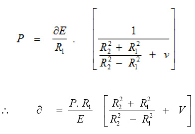
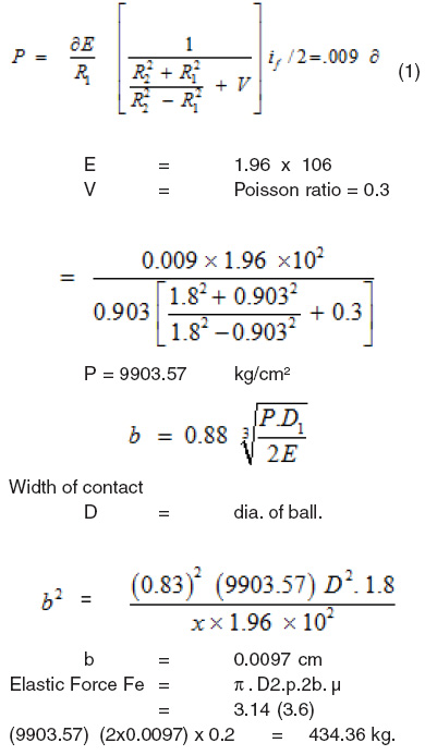
The cylindrical bush is subjected to uniform internal pressure. This pressure is calculated by the pressure equations given below : (33) (Referring to Diagrams 7a and 7b).
Load Calculations ::-(Forces and Pressure):-
Elastic Force Fe = π . D2. P. 2b. p
Plastic force Fp1 = π. D1. if. x 6
yield shear
stress
= p. D. if. t K
σ.K for Mild Steel = 15000 kg /cm2
σ. k for Aluminum = 6000 kg /cm2
Total load acting on the bush
= Elastic force + Plastic force
= Fe + Fp1
Where
R1 = 0.9 mm ( Radius of ball)
R2 = 18 mm ( Radius of bush)
∂ =if/2 = Either 0.009 or 0.004 mm as the case
may be.
v
= Poisson’s ratio
= 0.3 for steel and 0.34 for Aluminum
E = 1.96 x 10⁶ kg/cm2 for steel
= 0.675 x10⁶ kg/ cm2 for Aluminum
Elastic width of contact = 2b
b is calculated from Hertz’s equations
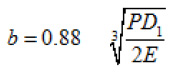
We have used D1 = 1.8= 2R1, because the plastic effect would be observed only in the internal diameter of the bush.
Similarly, D2 = 3.6 =2R2 as the elastic effect was observed in the entire bush thickness. It got bulged out when the ball was in the centre of bush length. (fig. 7b)
Designing and formulation
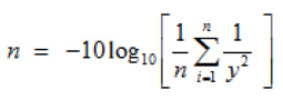
Where, y1= The observations of the quality characteristic under different noise conditions and n is the number of experiment.
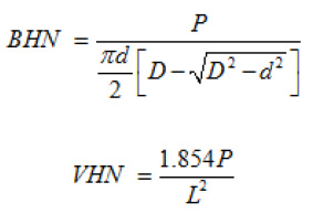
Where L = Diagonal length of the Indent πBHN & VHN = Range for steel
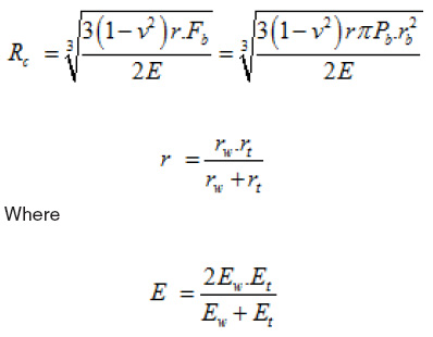
Fb= Pb.
π
.rt2 Force
R’2= rw = Bush/workpiece Radius
R1= rt = Ball(tool) Radius
d = Yielding stress of material
A= Contact Area during the BALLIZING process
A = pr2(-Cosa+1)
Where, a = Cos-1(r-h)/r
r = Radius of Ball h = Depth of penetration
Force = Yield stress x Area
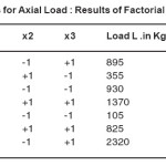
Evaluation of Forces for Different Interference
and With Help of Figures
The contact pressure force depends upon the mechanical properties of the work material, namely higher its hardness the greater is the contact pressure force needed to cause deformation. When radius of Ballizing tool is increased and the force remains constant, the contact area increases and contact pressure force is diminished.
The dependence of the contact pressure force upon the Ballizing force is not the same for hard and soft metals. For soft metals (unhardened steels, Aluminium Alloy s and alloys steel the contact pressure force, generally is constant.
Step-1
Mild steel bush with 180 microns interference
Plastic Force Fpl = π. D1 if x 6.00 K
6 K = 15000 kg.
= 3.14 (1.8) (0.018) x 15000
= 0.1017 x 15000
= 1526.04 kg
Total load = Fe + Fpl
= 434.36 + 1526.04 kg
= 1960.36 kg e4
Analysis and Evaluation
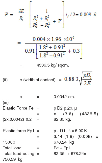
Step- 2
Mild steel bush with 80 microns interference. (Ref. fig. 7.2)
Case -1
Alloy Steel Bush with Interference of 180 Microns.
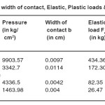
Results obtained from calculations based on the equations mentioned earlier :
p = 9903.57 Kg/cm2
b = 0.0097 cm
Fe = 4.34.36 kg
Fp1 = 1526.04 kg
Total load = 1960.36 kg
Case -2
Mild steel bush with interference of 80 microns.
p = 4336.5 Kg/cm2
b = 0.0042 cm
Fe = 82.35 kg
Fp1 = 678.24 kg
Total load = 750.59 kg
Remark
Some experimental load curve are very close to theoretically calculated values. 5.Mathematical calculation Load Equations :
We have :
Test experiment& simulation result of forces :
The test experiment were conducted under the conditions By force measuring system The measured BALLIZING force was obtained. The Simulation BALLIZING force under the same conditions was found.
The BALLIZING curve, the difference of absolute value between the measured and simulating BALLIZING force is little big. That is because according our assumptions the friction force, the feed force and other interference forces are neglected in model. but at that point the BALLIZING depth is very small and the BALLIZING forces is very small .relatively , the friction force, the feed force and other interference forces become very important parts of the BALLIZING composite forces. With an increase of the BALLIZING depth the BALLIZING force increases.
BALLIZING Force
As the ball BALLIZING force increases, the surface roughness decreases to a minimum value. Further increase in the force tends to increase the surface roughness, When high BALLIZING forces are applied, the bulge in front of the BALLIZING ball increases in size, and the region of plastic deformation widens. When this plastic deformation is repeated, as the BALLIZING tool passes along the surface, some damage of the surface is expected which will cause an increase in surface roughness
Mathematical Model for Evaluation of Forces
Ra= KfaVbSc
Where, Ra is surface roughness (mm), F, Vand S are the Force Speed (m/min), and feed (min/rev) repectively. Eq I be written as lnRa = lnk + alnF + blnV + clnS
which may represent the following linear mathematical model
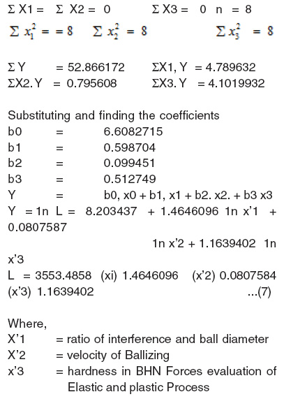
h= b0 X0+b1X1+b2 X2 + b3 X3
Where, h is the true response of surface roughness on a logarithmic scale,
X0= 1 (dummy variable), X1, X2, X3 ar logarithmic transformation of the force, speed and feed, while b0 ,b1, b2, b3 are the parameters to be estimated. Eq (3) can also be written as
Y1=Y-e =b0X0+b1X1+b2X2+b3X3
Where Yl is the esteemed response and Y is the measured surface roughness on a logarithmic scale. E is the experimental error and the b values are estimates of the b parameters.
Where, b values, that is b0, b1,b2, b3 are to be estimated the method of least squares, the basic formula is
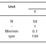
Co-Relation factors : Specimen speeds in rpm, tool feed rates in mm/rev; and depths of penetration (interference) in mm were used. Surface roughness (represented by Ra) proved to be improved by the process to an optimum speed, feed and clearance.
Results
Where ,
X1=Interference and X2=Velocity
X3=BHN +1= Higher limit -1 =Lower limit
Study and Evaluation of Different Forces 1 Mild Steel Bush With Interference of 190 Microns
Results obtained from calculations based on the equations mentioned earlier
p = 9903.57 Kg/cm2
b = 0.0097 cm
Fe = 4.34.36 kg
Fp1 = 1526.04 kg
Total load = 1960.36 kg
Mild Steel Bush With Interference of 70 Microns
p = 4336.5 Kg/cm2
b = 0.0042 cm
Fe = 82.35 kg
Fp1 = 678.24 kg
Total load = 750.59 kg
Discussion
(Ballizing )Force
The surface roughness decreases with increase in feed rate, BALLIZING speed, force, and number of tool passes, to a certain limit, then it starts to increase with each of the above-mentioned parameters.
The surface hardness decreases with an increase in feed rate and BALLIZING speed, while the hardness increases with the BALLIZING force and number of too passes.
An increase in BALLIZING force causes an increase in hardness and depth of the hardened subsurface layer.
The size of the BALLIZING ball has a significant effect on surface roughness and hardness.
Large diameter balls seem to be more effective in improv-ing surface roughness, while small diameter balls seems to be more effective in increasing surface hardness.
A surface roughness Ra of 0.1 mm and an increase in surface hardness of 60% could be obtained by BALLIZING turned cylindrical commercial aluminum and brass sur-faces by using the simple BALLIZING too designed in this study.
The microstructure examination shows that there is an elongation in the grain near the surface of the burnished work piece.
On the Result of Investigation Following Concluding Remarks can be Made
As the BALLIZING force increases, the surface roughness decreases to a minimum value. Further increase in the force tends to increase the surface roughness,
When high BALLIZING forces are applied, the bulge in front of the BALLIZING ball increases in size, and the region of plastic deformation widens.
When this plastic deformation is repeated, as the BALLIZING tool passes along the surface, some damage of the surface is expected which will cause an increase in surface roughness.
It has given very good results for bores ranging from 0.5 mm to 125 mm diameter.
The length to diameter ratio has also been recommended length should not be more than 10 times or less than 1/10 of the bore diameter.
Wall thickness should also be greater than 1/10th of bore diameter.
Ballizing gave good results for hole diameters of 1.5 mm to 25 mm.
Part to be ballized should not be harder than 45 Rc. The balls must be more hard than 65 Rc. (65 Rockwell C scale).
BALLIZING can be defined as a process in which a smooth but hard tool using sufficient pressure is rubbed on the surface of the metal. This helps to flatten the high spots by allowing plastic How of the metal.
Table 1
Table 2
Table 3
The edges of the metal can be smoothened by pushing it through a die that will smooth out the burrs and the blanked edge caused by the die break. . The main disadvantage is that super finishing requires grinding or a hard turning operation beforehand, which increases cost.
Advantages of Super Finishing Include
Increasing part life, decreasing wear, closer tolerances, higher load bearing surfaces, better sealing capabilities, and elimination of a break in period.
The main disadvantage is that super finishing requires grinding or a hard turning operation beforehand, which increases cost.
Super finishing has a lower cutting efficiency because of smaller chips and lower material removal rate. Super finishing stones are softer and wear more quickly, however they do not need to be dressed.
Advantages and Applications of Evaluation of
Different Forces for Ballizing Process
Common Applications Include
Steering rack components, transmission components, fuel injector components, camshaft lobes, hydraulic cylinder rods, bearing races, needle rollers, and sharpening stones and wheels. It has been proven that super finishing certain parts makes them more durable. For example if the teeth in a gear are super finished they will last up to four times as long.
BALLIZING can be defined as a process in which a smooth but hard tool using sufficient pressure is rubbed on the surface of the metal. This helps to flatten the high spots by allowing plastic How of the metal.
The edges of the metal can be smoothened by pushing it through a die that will smooth out the burrs and the blanked edge caused by the die break.
Ball BALLIZING (Ballizing ) tool are very versatile and can be used on most of the machine tools already installed in the shop, like turret lathes, engine lathes, drill machines or other CNC machines. In most cases, Ball BALLIZING operation can be integrated with the automatic cyclo indexing sequence, eliminating secondary operations.
BALLIZING occurs as an additional phase in machining processes. In turning, BALLIZING occurs if the cutting tool is not sharp, if a large negative rake angle is used, if a very small depth of cut is used, or if the work pieee material is tummy. As a cutting tool wears, it becomes blunter and the BALLIZING effect becomes more pronounced. In grinding, since the abrasive grains are randomly oriented and some are not sharp, there is always some amount of BALLIZING,This is one reason the grinding is less efficient and generates more heat than turning
BALLIZING tools operate at standard speeds and feeds found in the most conventional shop machines. BALLIZING process is a very low consumption power process due to the small amount of torque generated for machining. Workpiece fixturing problems are therefore considerably simplified when machine set-ups to be employed in surface finishing with this type tool.
BALLIZING also generates heat during due to rubbing between ball and work pieces. The heat generated at the deformation zone and friction zones over heats the tool and the work pieces Any standard grade, light weight, low-viscosity lubricating oil or any mineral, sulfur or soluble oil compatible with the metal or alloy to be burnished, is suitable for most metals. Coolant filtration s very important to keep metal particles or grit from being rolled(Ball) in to the part surface.
Study and Analysis Method Used
Gray analysis; Nural NA]; Talysurf Instrument ,Peak to Valley Height : Centre line Average Value : (j)The statistical method of Design of Experiments to establish a relationship between BHN, speed of Ballizing and interference. Reliability assessment of BALLIZING process is investigated theoretically and mathematical models are
proposed in this project.
Analysis of Variance (ANOVA)
the overll Grey relational grade and the aim should be to search a parameter setting
The purpose of analysis of variance is to investigate which BALLIZING parameters significantly effect the performance characteristics
Grey Relational Analysis
optimization of BALLIZING process for an optima parametric combination objective has been analyzed by Gardin ET
An Experimental Design (DOE) to Investigate
Used Taguchi technique to identify
Taguchi experimental design is carried out, a function be offered (efficiency evaluation) about one
Orthogonal Transformation
This statistical method of experiment is conducted to establish a relationship between the response variable R ,CNC,Universal Testing Machine the surface finish was measured by “Talysurf” Talysur gives surface finish value in terms of CLA in microns on digital display centre line average value (C.L.A.).
Ra(which is the arithmetic mean divination from the mean line) and also the shape of the load carrying capacity curve (progressive, digressive, etc.).
Horizontal Magniûcation was kept as 200 for all measurements while vertical one was adjusted according to the nature of the measured surface
References
- Dart, A. : ‘Improving Fatigue Strength of Metals-1, Machinery and production Engineering, (2004).
- Agrwal, A.S. : ‘Ballzing process for BALLIZING holes’ Dissertation for P.G. Diploma in Production Engineering (Royal College of Science and Technology Glasgow, U.K.). (1992).
- Fedrov, V.B. : Residual stresses and fatigue strength with centrifugal ball strain hardening. Trans. Of Ural polytechnical Institute, Col. 112, (1991).
- Enlimash and orgstankinprom : Improving gear efficiency by Burning Machine and Tooling, 3: 54 (1999).
- Torbilo, V.M. and Chekin, G.I. : Accuracy of diamond BALLIZING Machine and tooling No. 5: 32 (1999).
- Kononenko, V.T. and shamlin, V.Yu. : ‘Carbide BALLIZING unit for broaches’, Machine and Tooling No.8, pp 35 (2005).
- Khovrostukhin, L.A. and Mashov, V.N. : Effect of diamond BALLIZING on chromium plating Machine and Tooling No.6, pp45 (2000).
- Emel Tanov, V.N. : BALLIZING shaft fillets machine and tooling, No.6, pp31 (2001).
- Shneider et. al., Yu.G. : ‘Vibratory BALLIZING of machine tool parts ‘Machine and tooling No. 3, pp50 (2002).
- Ryzhov, E.V. ‘Increasing contact stiffness by vibratory BALLIZING’ machine and tooling No.1, pp59 (2002).
- Vestnik Mashinostroeniya : ‘Self Centering Three Roller Attachment with Instrument to check BALLIZING Forces’. Russian Engineering Journal, 57(7): pp59-69 (2007).
- Vestnik Mashinostroeniya : ‘Calculating the Depth of plastic Deformation when Stengthening parts by Plastic surface Deformation’. Russian Engineering Journal, Vol.59, Issue-1, pp19-23 [2009] – [2003]H.Joshi,Investigation of some effects of Ballizing on Aluminium Alloy and Mild Steel. First Indian Engg. 9-13 Calcutta (2003).
- H.Joshi,Investigation of Elastic and plastic forces in Ballizing process [Ballizing ] for Aluminium Alloy and Mild steel. First Indian Engg. 9-13 Calcutta, (2009).
- H.Joshi,Investigation of surface Effects in Ballizing on Aluminium Alloy and Mild Steel. First Indian Engg. (2010).
- H.Joshi Ballizing : A Tool for internal surface finishing (1990).
- Ugur Esme, Aysun Sagbas, Funda Kahraman”use of artificial neural networks in Ballizing process for the prediction of surface roughness of aa 7075 Aluminium Alloy alloy” uesme (2003).
- Ugur Esme, Aysun Sagbas, Funda\ Kahraman, M. Kemal Kulekci “uporaba umetnih nevronskih mre@ za napovedhrapavosti povr[ine pri krogelnem glajenju aluminijeve zlitine AA 7075 “uesme (2008).
- Paul S. Prevéy Lambda 5521 John T. Cammett “The Influence of Surface Enhancement by Low PlasticityBallizing on the Corrosion Fatigue Performance of AA7075-T6”
- Hongyun Luoa,, Jianying Liub, Lijiang Wangb, Qunpeng Zhonga “Study of the mechanism of theBallizing process with cylindrical polycrystalline diamond tools l221 (2005).
- Effect of Lubrication on Surface Finish and Surface Hardness of Ballized Component”
- U M Shirsat, Dr B B Ahuja, “Finishing of nonferrous internal surfaces using Ballizing technique (2002).
- Raja, Batu Pahat, Johor” Surface roughness investigation and hardness byBallizing on titanium alloy”
- Hongyun Luoa, Jianying Liub, Lijiang Wangb, Qunpeng Zhonga “Study of the mechanism of theBallizing process with cylindrical “(2005).
- S.Z. El-Abden, M. Abdel-Rahman, F.A. Mohamed “Finishing of non-ferrous internal surfaces using Ballizing technique” (2006).
- Zhao-Jun YANGJian-Ying liuocena niezawodnooeci operacji nagniatania stopu Aluminium Alloy reliability assessment of Ballizing operation of Aluminium Alloy
alloy “
- Dr. LaRoux K. Gillespie has a 40-year history with precision part production (2001).
- J. £abanowski*, A. OssowskaGdansk University of Technology, ul. Narutowicza 11/ 12, 80-952 Gdansk, Poland] 19(1): (2006).
- M.H. El-Axir, M.M. El-Khabeery, “Influence of orthogonalBallizing (Ballizing ) parameters(as force)on surface characteristics for various materials” 132: 82- 89 (2003).
- M.H. El-Axir, A.A. Ibrahim, Some surface characteristicsdue to center rest Ballizing . Journal of MaterialsProcessing Technology 167: 47-53 (2005).
CrossRef
- A.M. Hassan, A.M. Maqableh, The effects of initialBallizing parameters(as force)on nonferrous components. 102: 115-121 (2000).
- Zhao-jun yang jian-ying liuocena niezawodnooeci operacji nagniatania stopu “Aluminium Alloy reliability assessment of Ballizing operation of Aluminium Alloy alloy” (2009).

This work is licensed under a Creative Commons Attribution 4.0 International License.