Article

A New Energy-Absorbing Device for Motion Suppression in Deep-Sea Floating Platforms

*
Author to whom correspondence should be addressed.
Institute of Mechanics, Chinese Academy of Sciences, Beijing 100190, China
Energies 2015, 8(1), 111-132; https://doi.org/10.3390/en8010111
Submission received: 28 September 2014 / Accepted: 11 December 2014 / Published: 25 December 2014

Abstract

:
Deep-sea floating platforms are one of the most important large structures for ocean energy exploitation. A new energy-absorbing device named S-shaped Tuned Liquid Column Damper (TLCD) has been invented for the suppression of the horizontal motion and vertical in-plane rotation of a deep-sea floating platform. A conventional tuned liquid column damper has a U-shaped water tunnel to absorb the excessive energy of the main structure. The application of U-shaped dampers in deep-sea floating platforms is difficult due to the restriction of a large horizontal length. A novel S-shaped damper is proposed to retain the same amount of liquid using a shorter S-shaped tunnel. Theoretical and experimental works are conducted and prove that an S-shaped damper needs less than half the horizontal length to provide the same suppression as a U-shaped damper. A coupling calculation model is proposed and followed by the sensitivity analysis. The study demonstrates the applicability of the novel S-shaped damper for the motion suppression in deep-sea floating platforms.

1. Introduction

The scale of ocean energy exploitation has expanded considerably in the recent years [1,2,3]. Deep-sea floating platforms are some of the most important large structures for ocean energy exploitation. These platforms include Tension Leg Platforms (TLP), semi-submersible platforms and Spar platforms. Dynamic responses due to the wind and wave effects need to be considered for a safe design [4]. The combined action from both wind and wave effects leads to a large amplitude of vibration on the ocean platform [5,6]. Vibration is the main detrimental effect that reduces the safety and fatigue life of a deep-sea platform. In high-rise buildings, energy-absorbing devices are commonly being used to reduce the structural vibration by absorbing the excessive kinetic energy within the structure. This successful application may be transferable to solve the vibration problem in a floating platform, however, the natural period and motion amplitude are unique kinetic properties that exist in a floating platform and not in a high-rise building. Horizontal motion, vertical motion and vertical in-plane rotation due to vibration are the main situations to be prevented in a floating platform.
Vibration in a floating platform can be reduced by using active or passive controls [7,8]. Researchers have proposed various devices to control the vibration of a floating platform. Vibration-induced vertical motion of TLPs can be balanced by using absorbers with air springs [9,10,11]. Zhu et al. [12] and Ou et al. [13] proposed the Moveable Heave Plate (MHS) to simulate the mooring damping system to suppress the heave motion of a semi-submersible platform. Taflanidis et al. [14,15] designed multi-mass dampers to control the coupled heave and pitch dynamic responses of TLPs by using a simulation-based method. Fischer et al. [16] demonstrated the technical feasibility of using thrusters to mitigate Vortex Induced Motions (VIM) in spar platforms.
Previous research has focused on the suppression of heave motion and vertical in-plane rotation, but rarely the surge and sway motion discussed. The surge and sway motion is difficult to suppress with dampers. Deep-sea floating platforms are compliant platforms with flexible construction. The mooring pattern of the platform may not be able to restrict the platform’s plane motions of surge and sway, which have a long period and high amplitude. Limited research has discussed the Multi Degree of Freedom (MDOF) motion suppression of offshore floating platforms. The deep-sea floating platform has a complicated 6-dof motion in the ocean. Dampers are sometimes used to suppress one degree of freedom and this has a complicated influence on other degrees of freedom, so it is hard to achieve the MDOF motion suppression of a deep-sea floating platform.
Lee et al. [17,18] were the first to applied the Tuned Liquid Column Damper (TLCD) to migrate the vibration of surge and sway motions on floating platforms with experimental validation. TLCD is a type of passive control damping device, which is effective at suppressing the horizontal motion and vertical in-plane rotation. TLCD can utilize the resonance of a liquid column caused by external excitation to absorb the excessive energy of the main structure. The improvements of damper geometry and the working liquid in the devices provides better applications and safety for ocean structures. TLCD can be adapted into the existing devices on a platform including oil containers and water containers. However, the dynamic characteristics of a deep-sea floating platform restrict the application of conventional TLCDs. The natural period of the platform and the excitation period in deep seas are usually very long. A conventional TLCD used to suppress large period vibrations has a long horizontal length, larger than that of an offshore floating platform, therefore a shorter TLCD is required for application on a floating platform. In addition, regular TLCDs may increase the amplitude of the heave vibration and have a detrimental effect on safety and fatigue life, which is contrary to the original design intention.
This paper presents a novel S-shaped tuned liquid column damper used to suppress the horizontal motion and vertical in-plane rotation on a deep-sea floating platform. This damper is flexible so it can be installed on a deep-sea floating platform.

2. Novel S-Shaped TLCD

Passive control is usually used to suppress the vibration of structures by dissipating and absorbing the excessive energy [19]. The tuned liquid column damper (TLCD) is a passive control damper with a U-shaped water tunnel. A TLCD has two vertical columns connected to a horizontal tunnel to form a U-shaped device. The U-shaped damper is normally filled with water to absorb the vibration. Previous researchers proposed different kinds of TLCDs for offshore ocean structures. Huo and Li [20] analysed the performance of a circular TLCD in suppressing the torsion-induced vibration of an offshore platform. Mousavi et al. [21,22] evaluated the effectiveness of a Tuned Liquid Column Gas Damper (TLCGD) in the suppression of seismic-induced vibrations of steel jacket platforms. TLCD was also applied to floating wind turbines to reduce the vibration resulting from the wind and wave forces [23,24,25,26].
The motion suppression device described in this paper is in principle applicable to various kinds of deep-sea floating platforms. A tension leg platform (TLP) is used as an example throughout this study. Tension leg platforms are a kind of vertical mooring compliant platform, whose natural surge and sway period is above 100 s [27]. The horizontal motion with large amplitude in severe sea conditions could shorten the fatigue life of the tension leg and reduce the safety of the platform. When a TLP with 80 m × 80 m worktable interacts with ocean waves with a period of 20 s, the installation of a TLCD with the same period is suggested to suppress the horizontal motion. The total vertical length of the required U-shaped TLCD is above 200 m and its horizontal length is between 120 m and 150 m, which is larger than the size of the platform. U-shaped TLCDs were not designed to be used in deep-sea floating platforms.
Figure 1. Schematic diagram for an S-shaped TLCD.
Energies 08 00111 g001
An S-shaped TLCD is proposed to suppress the horizontal motion of a deep-sea floating platform. The horizontal portion has one or more S-shaped tubes with a shorter horizontal length compared to the U-shaped tube for the same amount of liquid, as shown in Figure 1. For the above TLP example, an S-shaped TLCD requires only half of the horizontal length (60 m) rather than 120–150 m for a U-shaped TLCD. The size of the S-shaped TLCD is smaller than that of the platform and this makes it applicable to deep-sea floating structures such as Spar platforms, semi-submersible platforms and wind turbines.

3. Theoretical Study

An S-shaped TLCD includes an L-shaped column, linear type column and U-shaped column as shown in Figure 1. The total length of the liquid column Ld and the horizontal length Lh are expressed in Equations (1) and (2) as:
L h = 2 ( B 1 + B 2 )
L d = 2 ( B 1 + B 2 + 2 B 3 + B 4 + H v )
The motion equation of an S-shaped TLCD can be established by the Lagrange equation and energy method is expressed in Equation (3) as:
d d t [ ( T U ) q ˙ i ] q i ( T U ) = Q i
where T is kinetic energy; U is potential energy; Qi is external force; qi is virtual displacement. The kinetic energy of this system is expressed in Equation (4) as:
T = 1 2 ρ d ( h H ) A H ˙ 2 + 1 2 ρ d ( h + H ) A d H ˙ 2 + 1 2 ρ d 2 B 4 A d ( H ˙ 2 + x ˙ 2 ) + 1 2 ρ d 2 B 3 A d ( x ˙ H ˙ ) 2 + 1 2 ρ d 2 ( B 1 + B 2 + B 3 ) A d ( x ˙ + H ˙ ) 2 + 1 2 M s x ˙ 2
where x is the horizontal displacement of main structures; H, H ˙ are the displacement and velocity of the liquid in the vertical tube, respectively. On the right hand side of the equation, the first, second and the third term are the kinetic energy of vertical liquid columns; the fourth and fifth term are the kinetic energy of the horizontal liquid columns; and the sixth term is the kinetic energy of the main structure.
The potential energy of this system is expressed in Equation (5) as:
U = H v r ρ d g z d V + H v l ρ d g z d V + 1 2 K s x ˙ 2 = 1 2 ρ d g A d ( h H ) 2 + 1 2 ρ d g A d ( h + H ) 2 + 1 2 K s x 2
where h is the average height of the water surface of the two vertical columns.
After substituting Equations (4) and (5) into Equation (3), the 2-DOF motion equations of the S-shaped TLCD fluid column and the main structure are given in Equations (6) and (7) as follows:
ρ d A d L d H ¨ + 1 2 ρ d h d | H ˙ | H ˙ + 2 ρ d g A d H = ρ d L h A d x ¨
( M s + ρ d A d L d ) x ¨ + C s x ˙ + K s X = F ( t ) ρ d A d L h H ¨
It is seen from the above principle equation that the natural period of the S-shaped damper is similar with the regular one, expressed as T = 2 π L d 2 g . Compared with a regular TLCD of the same total length of liquid column, an S-shaped TLCD reduces part of the horizontal length.
In the above analysis, the S-shaped TLCD has a simple form. The number of every type of column used in the device depends on the practical application requirements. If an S-shaped TLCD includes m S-shaped columns and n linear type columns, the total length of the liquid column is Ld and the effective horizontal length is Lh which are expressed in Equation (8) as:
L h = 2 B 1 + n B 2 L d = 2 B 1 + 2 L v + n B 2 + 4 m B 3 + 2 m B 4
where the total mass of liquid in device is md; the density of liquid is ρd; the acceleration of gravity is g; the cross-sectional area of liquid column is Ad; the head loss coefficient is hd; the mass of the main structure is Ms; the damping of main structure is Cs; the total stiffness of main structure is Ks; the external excitation is F(t); t the vertical length is Lv, the horizontal length of the L-shaped column is B1; the length of the linear type column is B2; half the length of one side of the S-shaped column is B3; and the lateral length of the S-shaped column is B4.

4. Experimental Investigation

An experimental study is conducted to verify the accuracy of the principle of the novel S-shaped TLCD. A vibration test system is designed with features of the large amplitude motion simulation, low-frequency performance and force control function. Physical models of regular and S-shaped TLCDs are also made, as shown in Figure 2 and Figure 3, respectively.
Figure 2. Regular TLCD No. 1.
Energies 08 00111 g002
Figure 3. S-shaped TLCD.
Energies 08 00111 g003
The S-shaped TLCD in Figure 3 is the simplest form with two U-shaped columns. The shaking table (natural period is 1.9 s) in the experiments produces a large amplitude motion. The response of the shaking table with or without dampers is presented in Figure 4 with different frequency ratios of excitation and shaking table.
Figure 4. Experimental and calculated vibration amplitude results.
Energies 08 00111 g004
The test is used to simulate the vibration in the deep-sea environment. The shaking table produces a large amplitude with 1.9 s of natural period. The S-shaped TLCD (in Figure 3) is used with the same natural period as the shaking table. Regular TLCD No. 1 (in Figure 2) has the same horizontal length and vertical height as the S-shaped TLCD. Both the S-shaped TLCD and Regular TLCD No. 1 are installed with an orifice plate. The plate has an opening rate of 0.6 under the external excitation. The numerical results from the regular TLCD were named Regular TLCD No. 2 with the same natural period of the shaking table, as shown in Figure 4. The head loss coefficient of Regular TLCD No. 2 is 14. According to [28], this is equivalent to the orifice plate with an opening rate of 0.4. The head loss coefficient of S-shaped TLCD is 6.5, which is equivalent to the orifice plate with a 0.6 opening rate.
The experimental results of the S-shaped TLCD agree with the calculated values. The vibration amplitude decreases by 27.5% from 60 cm to 43.5 cm using a S-shaped TLCD. Regular TLCD No. 1 has no vibration reduction effect. The S-shaped TLCD is an effective damper to suppress horizontal motion with a shorter horizontal length. The range of vibration control for the S-shaped TLCD and regular TLCD are basically the same. In addition, an S-shaped TLCD adds more damping than a regular TLCD for the same natural period. The flexible adjustment of the horizontal length and a smaller size of S-shaped tube provide a better solution to suppress vibrations with large period.

5. Coupling Calculation Model

The kinetic characteristics including natural period and amplitude are different for each degree of freedom in a floating platform, which increases the complication of suppression. Not only is it difficult for the damping device to suppress all motions resulting from the different degrees of freedom, but also the suppression of each degree influences the others. A numerical model of TLCDs with a 6-dof tension leg platform is established to analyse the feasibility of the S-shaped TLCD on a TLP and to explore the performance of each degree of freedom.
In recent years, TLCD improvements have been made to enhance the applicability and the damping effect. Hitchcock et al. [29,30] and Gao et al. [31] optimised the original TLCD by varying the cross section to overcome the narrow frequency band. In addition, the V-shaped TLCD had been designed to strengthen the vibration suppression. A dynamic equation of a TLCD of general shape was derived by Hochrainer [32] utilising the extended Bernoulli equation. Min et al. [33] proposed a tuned liquid mass damper for bidirectional control of the wind responses of a building in orthogonal directions. Improvement for a regular damper has been made in our calculation mode, which are: (1) the vertical column is inclined with respect to the horizontal column with an arbitrary angle; (2) the cross section of the vertical column and horizontal column of this device can vary.
Figure 5 shows the basic layout of a motion suppression system using multiple S-shaped TLCDs on a TLP. The vertical column usually has a large space over the liquid to facilitate the oscillation of the TLCD. If an S-shaped TLCD is installed underwater near the pontoons, the hollow parts of the vertical column provide additional buoyancy. Several S-shaped TLCDs should be installed on the worktable area to offset that additional buoyancy in order to keep the tension legs’ tension stable. An S-shaped TLCD with different installation arrangements (worktable area and underwater) has been used in our calculation model. Two S-shaped TLCDs in one plane should be placed symmetrically around the platform diagonal with any angle to have a good suppression effect on both surge and sway. When the platform shifts in every degree of freedom, the kinetic energy of the S-shaped TLCD and tension leg platform are respectively expressed by Equations (9) and (10) (detailed formulae are presented in Appendix 1):
T T L C D = T r i g h t vertical column + T l e f t vertical column + T h o r i z o n t a l c o l u m n
T p l a t f o r m = 1 2 M 1 X ˙ 1 2 + 1 2 M 2 X ˙ 2 2 + 1 2 M 3 X ˙ 3 2 + 1 2 M 4 X ˙ 4 2 + 1 2 M 5 X ˙ 5 2 + 1 2 M 6 X ˙ 6 2
The potential energy of the S-shaped TLCD and tension leg platform are respectively expressed in Equations (11) and (12) (detailed formulae are presented in Appendix 1):
U T L C D = U w o r k t a b l e + U u n d e r w a t e r
U p l a t f o r m = 1 2 K 1 X 1 2 + 1 2 K 2 X 2 2 + 1 2 K 3 X 3 2 + 1 2 K 4 X 4 2 + 1 2 K 5 X 5 2 + 1 2 K 6 X 6 2
Figure 5. S-shaped TLCDs installed on a tension leg platform.
Energies 08 00111 g005
The coupled motion equations of the S-shaped TLCD and TLP can be established by the Lagrange equation and energy method. The oscillation amplitude of the S-shaped TLCD on a TLP may be up to several meters, which is much larger than the amplitude of the surge, sway and heave motions. Therefore, the higher order terms referring to oscillation amplitude can be retained, but on the other hand, the higher order terms concerning the amplitude of surge, sway and heave can be neglected. The coupled motion equations are expressed in Equations (13)–(19) (detailed formulae are given in Appendix 1):
M X 1 X ¨ 1 + M X 1 H X ¨ 1 + K X 1 X 1 + C X ˙ 1 +   f X 1 ( X 5 X 6    H i ) = F ( t ) X 1
M X 2 X ¨ 2 + M X 2 H X ¨ 2 + K X 2 X 2 + C X ˙ 2 + f X 2 ( X 4 X ˙ 6 H i ) = F ( t ) X 2
M X 3 X ¨ 3 + M X 3 H X ¨ 3 + K X 3 X 3 + C X ˙ 3 + f X 3 ( X 4 X 5 H i ) = F ( t ) X 3
M X 4 X ¨ X 4 + M X 4 H X ¨ X 4 + K X 4 X X 4 + C X 4 X ˙ 4 + f X 4 ( X 2 X 3 X 5 X 6 H ) + f U X 4 ( X 4 X 5 X 6 H ) = M ( t ) X 4
M X 5 X ¨ X 5 + M X 5 H X ¨ X 5 + K X 5 X X 5 + C X 5 X ˙ 5 + f X 5 ( X 1 X 3 X 5 X 6 H ) + f U X 5 ( X 4 X 5 X 6 H ) = M ( t ) X 5
M X 6 X ¨ X 6 + M X 6 H X ¨ X 6 + K X 6 X X 6 + C X 6 X ˙ 6 + f X 6 ( X 1 X 2 X 4 X 5 H ) + f U X 6 = M ( t ) X 6
M H i H ¨ i + 1 2 ρ η ν 2 A h | H ˙ i | H ˙ i + f H i ( X ¨ 1 X ¨ 2 X ¨ 3 X ˙ 4 X ¨ 4 X ˙ 5 X ¨ 5 ) + f U H i ( X 4 X 5 H i ) = 0 ( i = 1 , 2 , 3 , 4 )
The results obtained by the model experiment and numerical calculation (the input parameters being that of the model) are well matched, as mentioned in Section 4. This validates the coupling calculation model. If the full scale system is to be investigated, the coupling calculation model can be used with the full scale parameters.

6. Sensitivity Analysis

Researchers have analysed the characteristic parameters of vibration suppression with TLCDs and formulated optimisation design methods for high-rise building [34,35,36]. None of research has referred to a solution for deep-sea floating platforms and the impact analysis of the characteristic parameters of TLCDs applied on deep-sea floating platforms. In this study, selection criteria of motion suppression systems on TLPs are proposed based on the analysis of its key parameters for a TLP. With the help of the calculation model and experimental design form [36,37], the numerical orthogonal test analysis has been performed with the seven factors listed in Table 1. Every level is chosen according to the experience in computation and the actual situation. A large number of numerical simulations are carried out based on two orthogonal design tables with different wave period (a detailed table is provided in Appendix 2).
The seven factors are the inclination of vertical liquid column (x1) (β in Figure 5), the length ratio of horizontal liquid column and vertical liquid column (x2), the ratio of horizontal length and total horizontal length (x3), the depth of underwater installation (x4), the cross-section ratio of vertical liquid column and horizontal liquid column (x5), the angle between the incident wave and the S-shaped TLCD (x6) (γ in Figure 5) and the head loss coefficient (x7).
Table 1. Selection of factors in numerical orthogonal test.
FactorLevel 1Level 2Level 3Level 4Level 5Level 6Level 7
x1 (°)60708090100110120
x22.02.332.673.03.333.674.0
x30.520.60.680.760.840.921
x4 (m)04812162024
x50.81.01.21.41.61.82.0
x6 (°)3.510.417.324.231.238.145
x71.01.783.165.6210.017.7831.62
Except for some basic parameters of TLCDs in high-rise building such as x2 and x7, some specific parameters of S-shaped TLCDs caused by the actual working conditions have been added to the analysis such as x4, x6. For example, x4 can change the wave force acting on the platform, which affects the suppression effect of the pitch and roll on the TLP. In addition, x3 is the characteristic parameter for distinguishing an S-shaped TLCD from a regular one. Some factors representing for the improvement of the S-shaped TLCD must also be investigated such as x1, x5. During the analysis, the excitation force due to incident waves is always from 45 degrees to an axis of symmetry on the TLP, so the effect of the suppression system on yaw is not considered. The quality and period of the S-shaped TLCD are not changed in this analysis, respectively. The structural data of the TLP is chosen according to [4].
Figure 6 shows the results of range analysis for the responses of surge, sway, heave and pitch. It is seen that the range analysis results with different period are basically the same. The term x5 has the biggest influence on the response of every degree of freedom among the seven factors, especially in surge sway and heave. The term x3 also has more influence on the motion suppression of every degree of freedom. The term x2 has a slightly larger effect on the response of translational degrees of freedom such as surge, sway, and heave, while x3 has some impact on the response of heave, roll and pitch. The influence of other factors can be neglected. Further analysis is undertaken on those factors with significant influence by comparing the mean amplitude with a wave period T = 12 s. Figure 7, Figure 8, Figure 9 and Figure 10 show the motion amplitude of every degree of freedom as a function of the cross-section ratio of the vertical liquid column and horizontal liquid column (x5), the ratio of horizontal length and total horizontal length (x3), the inclination of the ertical liquid column (x1), and the length ratio of the horizontal liquid column and vertical liquid column (x2).
Figure 6. Range analysis of surge, sway, heave, pitch, roll for (a) surge, sway; (b) heave; (c) roll, pitch.
Energies 08 00111 g006
Figure 7. Comparison of responses for x5 for (a) surge, sway; (b) heave; (c) roll, pitch.
Energies 08 00111 g007
Figure 8. Comparison of responses for x3 for (a) surge, sway; (b) heave; (c) roll, pitch.
Energies 08 00111 g008aEnergies 08 00111 g008b
Figure 9. Comparison of responses for x1 for, (a) heave; (b) roll, pitch.
Energies 08 00111 g009
Figure 10. Comparison of responses for x2 for (a) surge, sway; (b) heave.
Energies 08 00111 g010
In Figure 7, the optimal suppression effect on the response surge and sway can be obtained with x5 = 1.0. In other words, the S-shaped TLCD with uniform cross section has the best suppression effect, which is different from the result of a regular TLCD [34]. Only when the cross-section ratio is greater than 1.4, can S-shaped TLCDs simultaneously suppress the response of every degree of freedom. There is a reciprocal relationship between surge, sway and heave for suppression effects in the range of x5 = 1.4 to x5 = 2.0. When the suppression effect on surge and sway reduces from 21% to 13%, the heave increases its suppression effect by 35%. It is demonstrated that the total dissipated energy for translational degrees of freedom may not increase by changing the factor x5, but it can change the proportion of dissipated energy for surge, sway and heave. The factor x5 has almost the same influence on an S-shaped TLCD and a regular TLCD by comparing with [38]. The motion suppression system maintain a relatively stable suppression effect on the response of pitch and roll over x5 = 1.4.
The factor x3 is the characteristic parameter for distinguishing an S-shaped TLCD from a regular one. As shown in Figure 8, an S-shaped TLCD can be changed into a regular TLCD at x3 = 1. For surge and sway, the suppression effect jumps between 13% and 22% with the change of x3. The suppression effect on pitch and roll is stable at 30%, when x3 varies from 0.7 to 0.9. After that, it sharply increases and reaches 45% at x3 = 1.0. However, Figure 8b shows that the heave response is in a state of deterioration. The deterioration effect of the heaving response is maintained between 3% and 7% at x3 = 0.5–0.9 and it exceeds 15% at x3 = 1.0. The results demonstrate that an S-shaped TLCD has a smaller deteriorating effect. In general, though an S-shaped TLCD has less motion suppression effect than a regular TLCD for pitch and roll, the deteriorating effect on the heaving response can be controlled within an acceptable limit by an S-shaped TLCD. Hence, this is another advantage for an S-shaped TLCD installed on a TLP.
As shown in Figure 9, only when the inclination exceeds 105°, can an S-shaped TLCD have a suppression effect on the heave motion. The motion suppression effect on pitch and roll gradually declines with the increase of x1. After the inclination exceeds 100°, the suppression effect increases slightly. Based on the observations of Figure 9, selecting an inclination from 90° to 100° is sensible, which not only ensures a stable suppression effect on the pitch and roll response, but also has smaller negative impacts on the heave response. If an S-shaped TLCD is needed to suppress the motion of every degree of freedom, the inclination of the vertical liquid column can be chosen near 120°. Figure 10 shows the factor x2 can make an S-shaped TLCD change the energy transmission relationship between surge, sway and heave.
In conclusion, the study demonstrates the applicability of the novel S-shaped damper for motion suppression in deep-sea floating platforms. The S-shaped damper needs less than half of the horizontal length to provide the same suppression as a regular U-shaped damper. Though the S-shaped TLCD has less motion suppression effect than a regular TLCD for pitch and roll, the deteriorating effect on the heaving response can be controlled within acceptable limits. This is another advantage for installing S-shaped TLCDs on TLPs.

7. Conclusions

This study proposes an effective energy-absorbing S-shaped TLCD device. This system can improve the safety and fatigue life of TLPs by mitigating the large amplitude vibration of deep-sea floating platforms. Theoretical, experimental and coupling calculation models were used to validate the S-shaped TLCD. The main findings are:
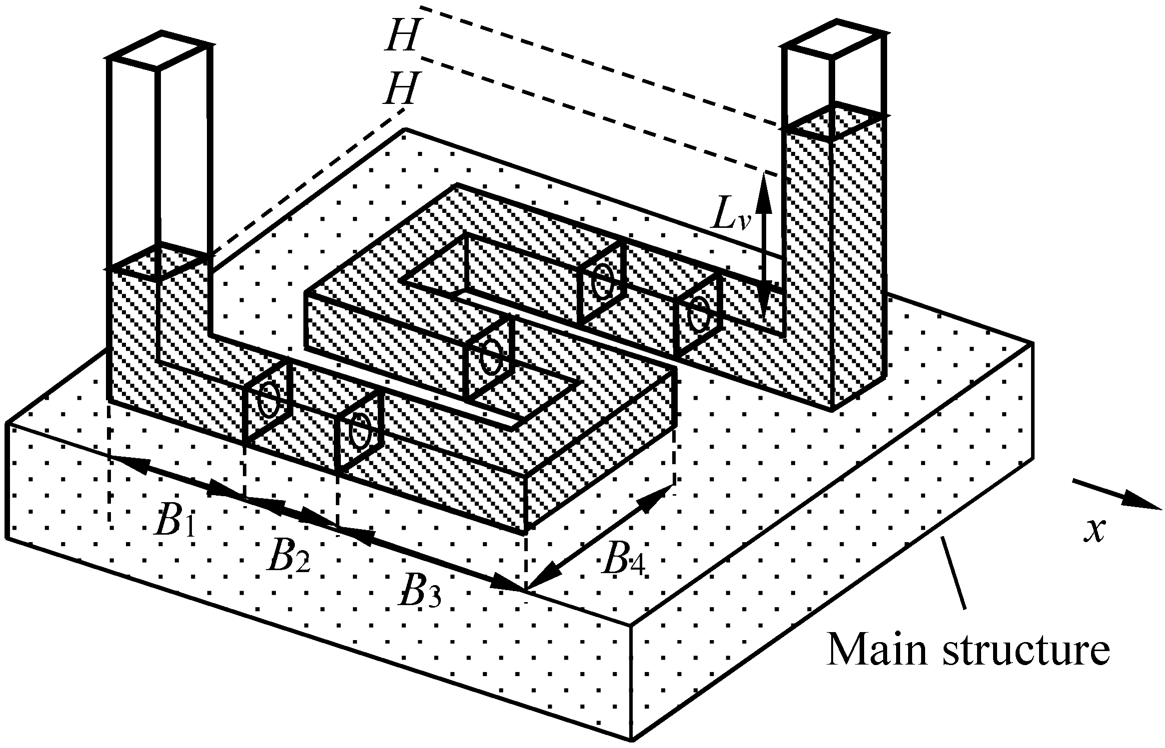
  • The S-shaped TLCD is suitable for suppressing the horizontal motion and vertical in-plane rotation of main structures with large inherent periods by using the method of energy absorption. An S-shaped TLCD can function with a substantially shorter horizontal length compared to a conventional U-shaped TLCD. The short effective horizontal length makes the S-shaped TLCD easier to install on TLPs.
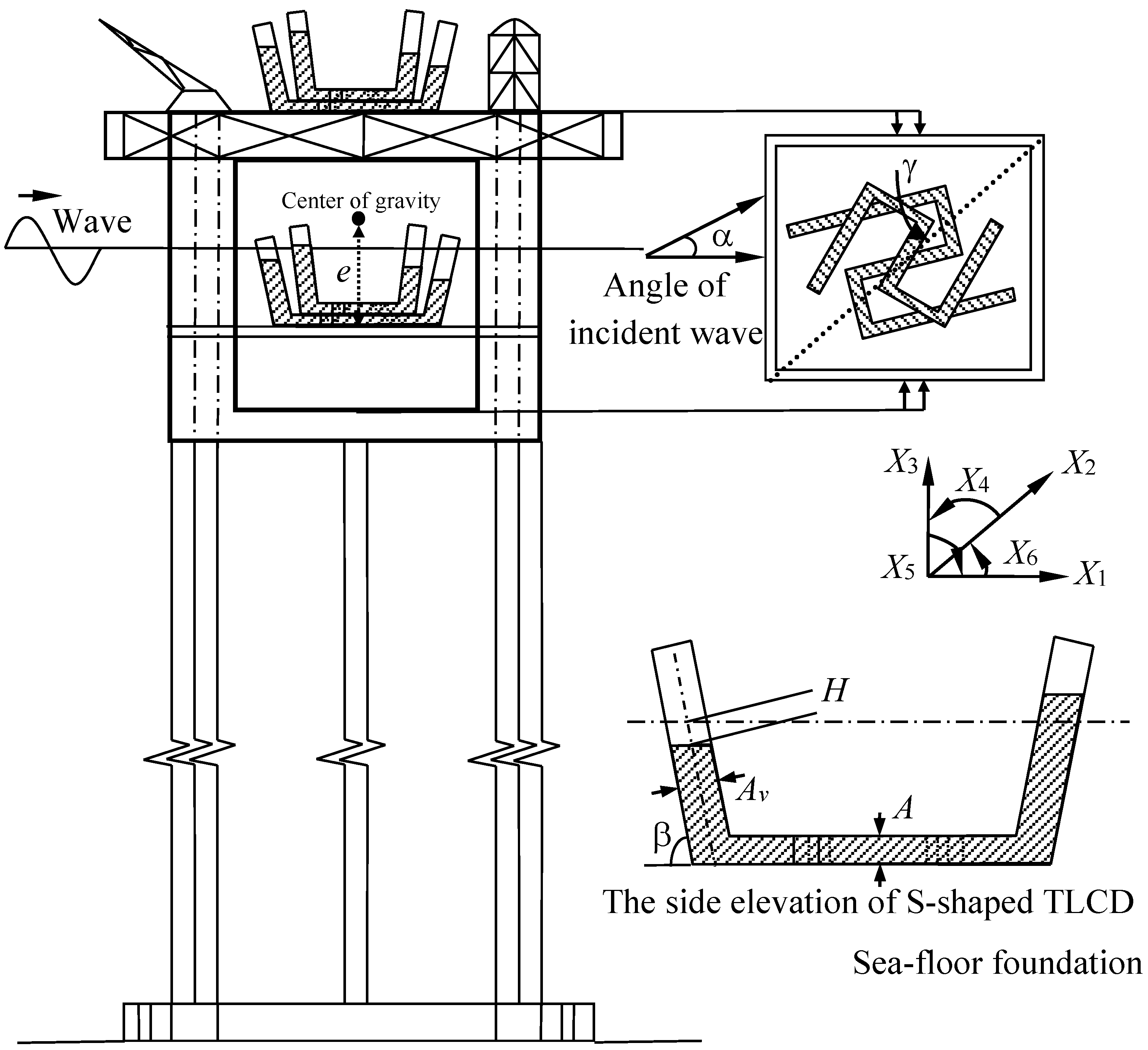
  • A coupling calculation model capable of analyzing the dynamic responses of TLPs with S-shaped TLCDs is established. Various factors contributing to the improvements of TLCDs such as the inclination of the vertical liquid column, the cross-section ratio of the vertical liquid column and horizontal liquid column are considered.
  • The sensitivity analysis finds:
    (a)
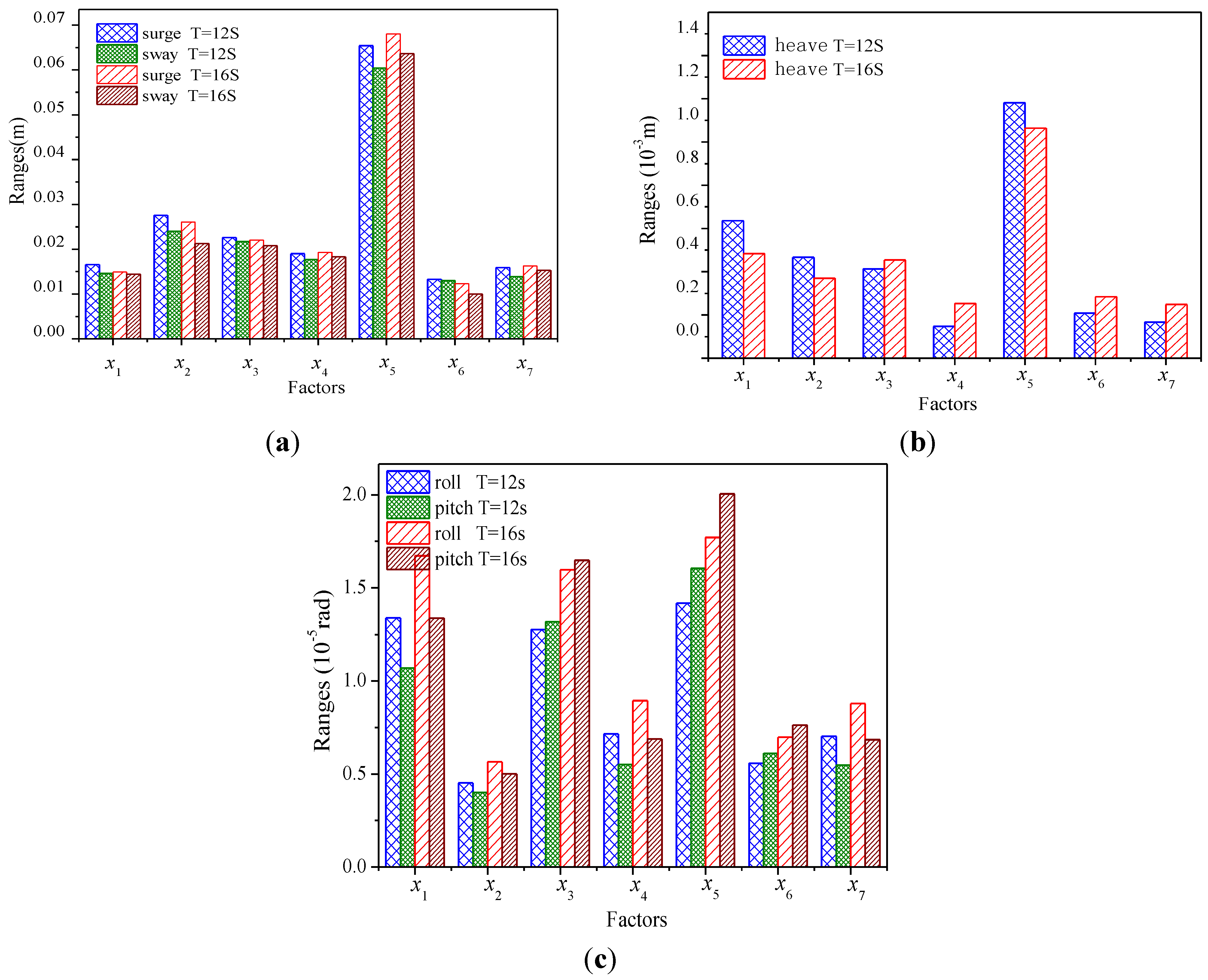
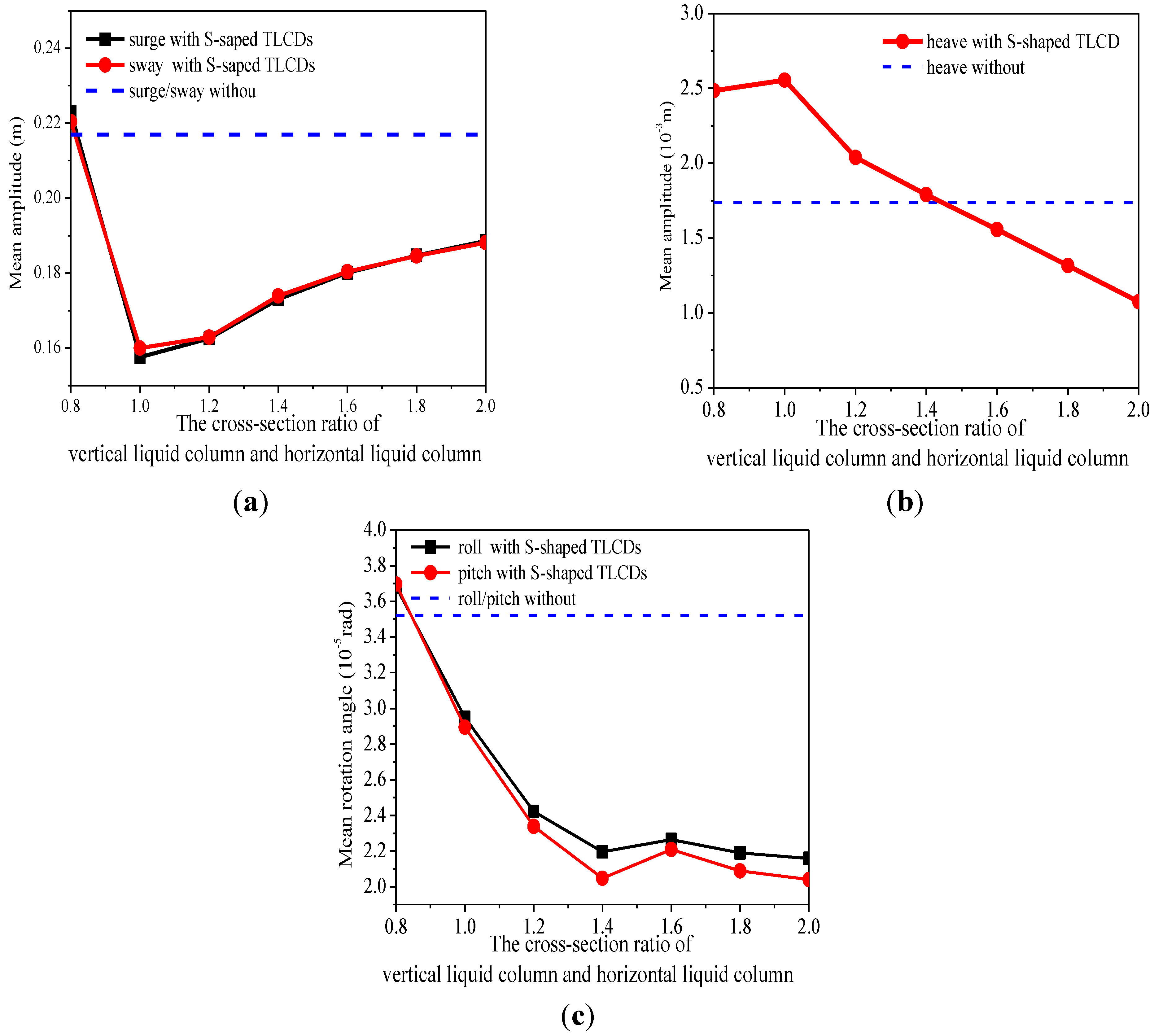
    The cross-section ratio of the vertical liquid column and horizontal liquid column (x5) has the biggest influence on the response of every degree of freedom among seven factors;
    (b)
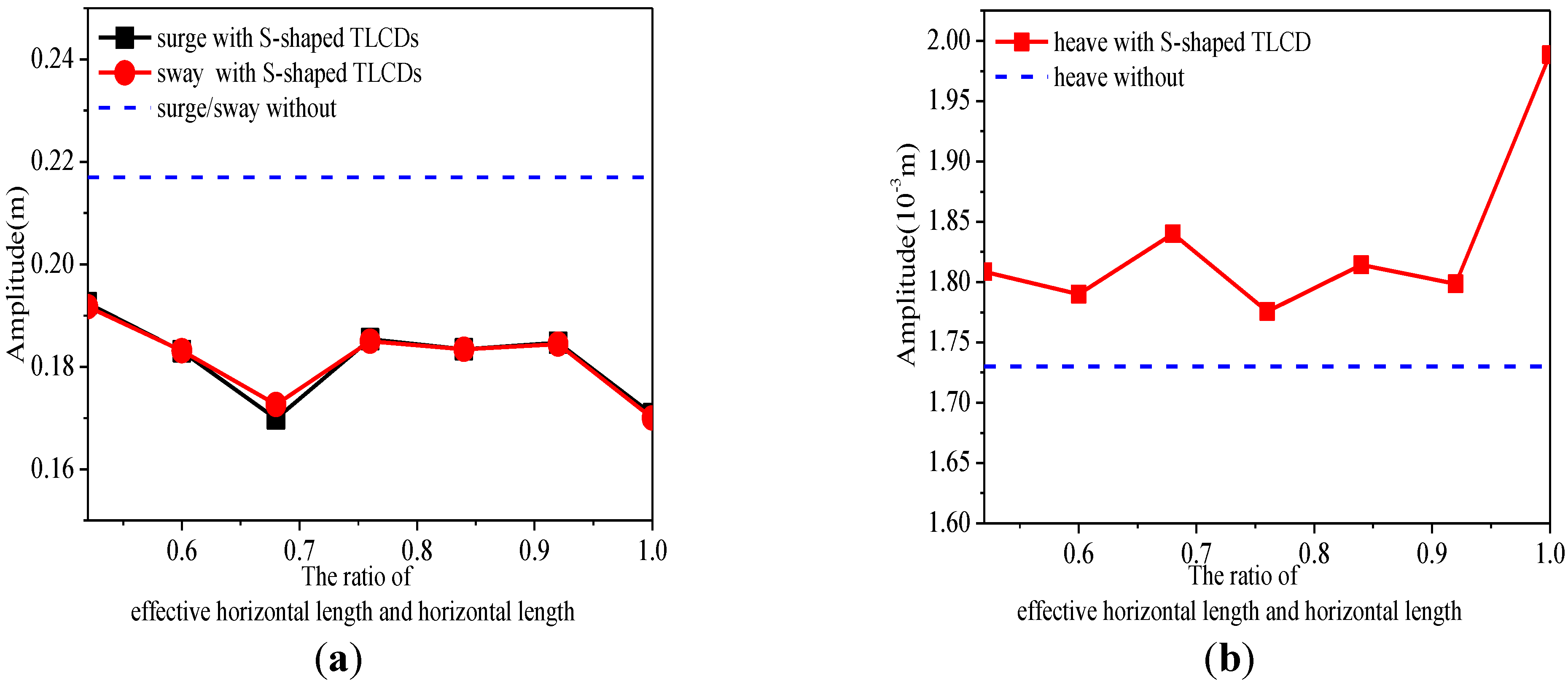
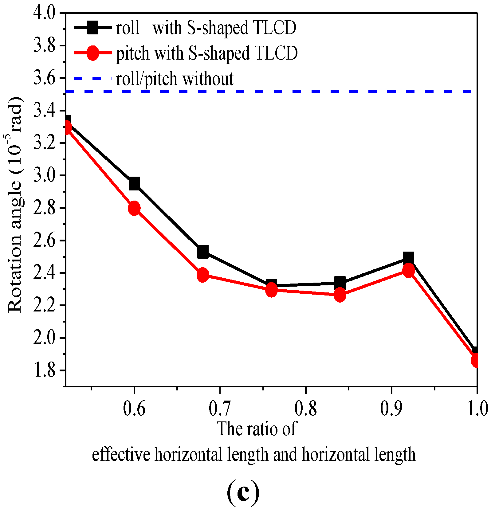
    The ratio of effective horizontal length and horizontal length (x3) also has a big influence on the response of every degree of freedom;
    (c)
    The length ratio of the horizontal liquid column and vertical liquid column (x2) has some influence on the surge, sway and heave response, the same as the inclination of vertical liquid column (x1) for the heave, pitch and roll response.
  • A S-shaped TLCD with uniform cross section has the best suppression effect on the surge and sway response. Selection criteria for motion suppression systems on TLPs are also proposed based on the responses of each degree of freedom.

Acknowledgments

The authors would like to express their gratitude for the financial support of the National Natural Science Foundation of China (Grant Nos. 11072246, 51490673, 10702073), and the National Basic Research Program of China (973 Program 2014CB046801).

Author Contributions

Xiaohui Zeng put forward the overall idea. Yang Yu contributed to the theoretical and experimental analysis, and wrote the manuscript. Liang Zhang contributed to the experimental study. Qingquan Liu contributed to data analysis. Han Wu contributed to data analysis.

Appendix 1

The kinetic energy of every part of an S-shaped TLCD are respectively expressed as:
T l e f t v e r t i c a l   c o l u m n = 1 2 ρ A v 0 L v H ( X ˙ 1 + H ˙ cosβcos α 1 + X ˙ 5 ( e + l ) sinβ + X ˙ 6 ( L h 2 + l cosβ ) sin α 1 ) 2 d l    + 1 2 ρ A v 0 L v H ( X ˙ 2 + H ˙ cosβsin α 1 X ˙ 4 ( e + l ) sinβ X ˙ 6 ( L h 2 + l cosβ ) cos α 1 ) 2 d l    + 1 2 ρ A v 0 L v H ( H ˙ sinβ + X ˙ 5 ( L h 2 + l cosβ ) cos α 1 X ˙ 4 ( L h 2 + l cosβ ) sin α 1 + X ˙ 3 ) 2 d s
T r i g h t v e r t i c a l   c o l u m n = 1 2 ρ A v 0 L v + H ( X ˙ 1 + H ˙ cosβcos α 1 + X ˙ 5 ( e + l ) sinβ X ˙ 6 ( L h 2 + l cosβ ) sin α 1 ) 2 d l     + 1 2 ρ A v 0 L v + H ( Y ˙ + H ˙ cosβsin α 1 θ ˙ x ( e + l ) sinβ + X ˙ 6 ( L h 2 + l cosβ ) cos α 1 ) 2 d l    + 1 2 ρ A v 0 L v + H ( H ˙ sinβ X ˙ 5 ( L h 2 + l cosβ ) cos α 1 + X ˙ 4 ( L h 2 + l cosβ ) sin α 1 + X ˙ 3 ) 2 d s
T h o r i z o n t a l c o l u m n = 1 2 ρ A h L h 2 B 3 ( ν H ˙ cos α 1 + X ˙ 5 e + X ˙ 1 X ˙ 6 l sin α 1 ) 2 d l + 1 2 ρ A h L h 2 B 3 ( ν H ˙ sin α 1 X ˙ 4 e + X ˙ 2 + X ˙ 6 l cos α 1 ) 2 d l      + 1 2 ρ A h L h 2 B 3 ( X ˙ 3 X ˙ 5 l cos α 1 + X ˙ 4 l sin α 1 ) 2 d l      + 1 2 ρ A h B 3 B 3 ( ν H ˙ cos α 1 + X ˙ 5 e + X ˙ 1 X ˙ 6 l sin α 1 ) 2 d l + 1 2 ρ A h B 3 B 3 ( ν H ˙ sin α 1 X ˙ 4 e + X ˙ 2 + X ˙ 6 l cos α 1 ) 2 d l      + 1 2 ρ A h B 3 B 3 ( X ˙ 3 X ˙ 5 l cos α 1 + X ˙ 4 l sin α 1 ) 2 d l      + 1 2 ρ A h B 3 L h 2 ( ν H ˙ cos α 1 + X ˙ 5 e + X ˙ 1 X ˙ 6 l sin α 1 ) 2 d l + 1 2 ρ A h B 3 L h 2 ( ν H ˙ sin α 1 X ˙ 4 e + X ˙ 2 + X ˙ 6 l cos α 1 ) 2 d l      + 1 2 ρ A h B 3 L h 2 ( X ˙ 3 X ˙ 5 l cos α 1 + X ˙ 4 l sin α 1 ) 2 d l      + 1 2 ρ A h B 4 B 4 ( ν H ˙ sin α 1 + X ˙ 5 e + X ˙ 1 X ˙ 6 l cos α 1 ) 2 d l + 1 2 ρ A h B 4 B 4 ( ν H ˙ cos α 1 X ˙ 4 e + X ˙ 2 + X ˙ 6 l sin α 1 ) 2 d l      + 1 2 ρ A h B 4 B 4 ( X ˙ 3 + X ˙ 5 l sin α 1 + X ˙ 4 l cos α 1 ) 2 d l
The potential energy of every part of a S-shaped TLCD on the worktable is expressed as:
U w o r k t a b l e = ρ g A v ( L v H ) [ ( e + L v H 2 sinβ ) + L h 2 cos α 1 X 5 L h 2 sin α 1 X 4 ]     + ρ g A v ( L v + H ) [ ( e + L v + H 2 sinβ ) L h 2 cos α 1 X 5 + L h 2 sin α 1 X 4 ]     + ρ g A h ( 2 B 1 + 2 B 2 + 2 B 3 + 2 B 4 ) e cos X 4 cos X 5
The potential energy of every part of as S-shaped TLCD underwater is expressed as:
U u n d e r w a t e r =   ρ g A v ( L v H ) [ ( e + L v H 2 sinβ ) + L h 2 cos α 1 X 5 L h 2 sin α 1 X 4 ]     ρ g A v ( L v + H ) [ ( e + L v + H 2 sinβ ) L h 2 cos α 1 X 5 + L h 2 sin α 1 X 4 ]     ρ g A h ( 2 B 1 + 2 B 2 + 2 B 3 + 2 B 4 ) e cos X 4 cos X 5
Every term of the coupled motion equations is expressed as:
M X 1 H i = ρ A h ( 2 ν L v + ( L h + 4 B 3 + 2 B 4 ) ) M X 2 H i = ρ A h ( 2 ν L v + ( L h + 4 B 3 + 2 B 4 ) ) M X 3 H i = ρ A h ( 2 ν L v + ( L h + 4 B 3 + 2 B 4 ) ) M H i = ρ A h ν ( 2 L v + ν ( L h + 4 B 3 + 2 B 4 ) )
M X 4 H i = ρ A h ( ( L h + 4 B 3 + 2 B 4 ) e 2 + 1 3 ( L h 3 4 + 4 B 3 3 + 2 B 4 3 ) sin 2 α 1 + 2 3 ν L v 3 + 2 e 2 L v sin β 2 + 2 e L v 2 sin β 2 + 1 2 ν L v L h 2 sin 2 α 1 ) M X 5 H i = ρ A h ( ( L h + 4 B 3 + 2 B 4 ) e 2 + 1 3 ( L h 3 4 + 4 B 3 3 + 2 B 4 3 ) sin 2 α 1 + 2 3 ν L v 3 + 2 e 2 L v sin β 2 + 2 e L v 2 sin β 2 + 1 2 ν L v L h 2 sin 2 α 1 ) M X 6 H i = ρ A h ( 1 3 ( L h 3 4 + 4 B 3 3 + 2 B 4 3 ) + 1 2 ν L v L h 2 sinβ )
f X 1 = ρ A h ( ( L h + 4 B 3 + 2 B 4 ) e + ν L v 2 + 2 ν L v e sinβ ) X ¨ 5 + ρ A v H 2 X ¨ 5 + 2 ρ A v H X ˙ 5    2 ρ A v L v cosβsin α 1 H X ¨ 6 2 ρ A v L v cosβsin α 1 H ˙ X ˙ 6 ρ A v L h sin α 1 H X ¨ 6    ρ A v L h sin α 1 H ˙ X ˙ 6 + 2 ρ A v L v cosβcosα H ¨ i + ρ A h ν ( L h cos α 1 + 2 B 4 sin α 1 ) H ¨ i
f X 2 = ρ A h ( ( L h + 4 B 3 + 2 B 4 ) e + ν L v 2 + 2 ν L v e sinβ ) X ¨ 4 ρ A v H 2 X ¨ 4 2 ρ A v H X ˙ 4    + 2 ρ A v L v cosβcos α 1 H X ¨ 6 + 2 ρ A v L v cosβcos α 1 H ˙ X ˙ 6 + ρ A v L h cos α 1 H X ¨ 6    + ρ A v L h cos α 1 H ˙ X ˙ 6 + 2 ρ A v L v cosβsinα H ¨ i + ρ A h ν ( L h sin α 1 2 B 4 cos α 1 ) H ¨ i
f X 3 = + ρ A v L h sin α 1 H X ¨ 4 + ρ A v L h sin α 1 H ˙ X ˙ 4 ρ A v L h cos α 1 H X ¨ 5 ρ A v L h cos α 1 H ˙ X ˙ 5 + 2 ρ A v H H ¨ sinβ + 2 ρ A v H ˙ H ˙ sinβ + ρ A v ( X ¨ 5 cos α 1 X ¨ 4 sinα ) cosβ ( H 2 + L v 2 ) + 2 ρ A v H ( X ˙ 5 cos α 1 X ˙ 4 sinα ) cosβ
f X 4 = ρ A h ( ( L h + 4 B 3 + 2 B 4 ) e + ν L v 2 sinβ + 2 ν L v e sinβ ) X ¨ 2    ρ A v H 2 sinβ X ¨ 2 ρ A v sin α 1 cosβ ( L v 2 + H 2 ) X ¨ 3    ρ A h ν ( L h sin α 1 2 B 4 cos α 1 ) e H ¨ ρ A v L v sin α 1 sinβcosβ e H ¨    + ρ A v L v L h sin α 1 sinβ H ¨ ρ A v cosβsinβsinα ( L v 2 + H 2 ) H ¨    ρ A h ( 1 2 ν L v L h 2 sin α 1 cos α 1 + 1 3 ( L h 3 4 + 4 B 3 3 + 2 B 4 3 ) sin α 1 cos α 1 ) X ¨ 5    ( ρ A v L h cos α 1 sinβ ( e + L v ) + 2 ρ A v cos α 1 sinβ L v e ) ( H X ¨ 6 + H ˙ X ˙ 6 )    + 2 ρ A v ( e + L v sinβ ) H 2 X ¨ 4 2 ρ A v H sinβ ( Y ˙ + H ˙ sinαcosβ )    A v L h sin α 1 H ˙ X ˙ 3 + ρ A v L h sin α 1 H X ¨ 3 2 ρ A v sin α 1 cosβ H X ˙ 3    2 ρ A v sin α 1 s sinβcosβ L v ( H ¨ H + H ˙ 2 )    + 4 ρ A v ( e + L v ) sinβ H X ˙ 4 ρ A v L h cos α 1 ( e + L v ) H ˙ X ˙ 6
f U X 4 = ρ g A h L h e X 4 ρ g A v H 2 X 4 + ρ g A v L h cos α 1 H X 6    + ρ g A v L h cos α 1 H X 4 X 5 ρ g A v L h sin α 1 H X 4 X 5 X 6 + ρ g A v L h sin α 1 H
f X 5 = ρ A h ( ( L h + 4 B 3 + 2 B 4 ) e + ν L v 2 sinβ + 2 ν L v e sinβ ) X ¨ 1    + ρ A v H 2 sinβ X ¨ 1 + ρ A v cos α 1 cosβ ( L v 2 + H 2 ) X ¨ 3    + ρ A h ν ( L h cos α 1 + 2 B 4 sin α 1 ) e H ¨ + ρ A v L v cos α 1 sinβcosβ e H ¨    ρ A v L v L h cos α 1 sinβ H ¨ + ρ A v H ¨ cosβsinβcosα ( L v 2 + H 2 )    ρ A h ( 1 2 ν L v L h 2 sin α 1 cos α 1 + 1 3 ( L h 3 4 + 4 B 3 3 + 2 B 4 3 ) sin α 1 cos α 1 ) X ¨ 4    + ( ρ A v L h sin α 1 sinβ ( e + L v ) + 2 ρ A v sin α 1 sinβ L v e ) ( H X ¨ 6 + H ˙ X ˙ 6 )    + 2 ρ A v ( e + L v sinβ ) H 2 X ¨ 5 + 2 ρ A v H sinβ ( X ˙ 1 + H ˙ cosαcosβ )    ρ A v L h cos α 1 H X ¨ 3 ρ A v L h cos α 1 H ˙ X ˙ 3 + 2 ρ A v cos α 1 cosβ H X ˙ 3    + 2 ρ A v cos α 1 s sinβcosβ L v ( H ¨ H + H ˙ 2 )    + 4 ρ A v ( e + L v ) sinβ H X ˙ 5 ρ A v L h sin α 1 ( e + L v ) H ˙ X ˙ 6
f U X 5 = ρ g A v L v ( L v sinβ + 2 e ) X 5 ρ g A h L h e X 5 ρ g A v H 2 X 5    + ρ g A v L h sin α 1 H X 6 ρ g A v L h cos α 1 H
f X 6 = ρ A v ( e + L v ) L h cos α 1 sinβ H X ¨ 4 + ρ A v ( e + L v ) L h cos α 1 sinβ H ˙ X ˙ 4    ρ A v ( e + L v ) L h sin α 1 sinβ H X ¨ 5 ρ A v ( e + L v ) L h sin α 1 sinβ H ˙ X ˙ 5    ρ A v L h sin α 1 sinβ H ( X ¨ 1 + H ¨ cosβcos α 1 ) ρ A v L h cos α 1 sinβ H ( X ¨ 2 + H ¨ cosβsin α 1 )
f U X 6 = ρ A v L h sin α 1 sinβ H ˙ ( X ˙ 1 + H ˙ cosβcos α 1 ) ρ A v L h cos α 1 sinβ H ˙ ( X ˙ 2 + H ˙ cosβsin α 1 )
f H i = ρ A h ν ( L h cos α 1 + 2 B 4 sin α 1 ) X ¨ 1 + 2 ρ A h ν cosβ ( L v cos α 1 X ¨ 1 + L v sin α 1 X ¨ 2 )    + ρ A h ν ( L h sin α 1 2 B 4 cos α 1 ) X ¨ 2 + 2 ρ A v H X ¨ 3 sinβ    + ( ρ A h ν ( ( L h + 4 B 3 ) e sin α 1 2 B 4 e cos α 1 ) 2 ρ A v sinβcosβsin α 1 L v e + ρ A v L v L h sin α 1 sinβ ) X ¨ 4     + ( ρ A h ν ( ( L h + 4 B 3 ) e cos α 1 2 B 4 e sin α 1 ) + 2 ρ A v sinβcosβcos α 1 L v e ρ A v L v L h cos α 1 sinβ ) X ¨ 5    + ρ A v ( X ¨ 5 cos α 1 X ¨ 4 sin α 1 ) ( H + L v ) 2 sinβcosβ    + 2 ρ A v ( X ¨ 5 cos α 1 X ¨ 4 sin α 1 ) ( H + L v ) sinβcosβ + 2 ρ A v H ˙ Z ˙ sinβ
f U H i = 2 ρ A v g H sinβ ρ g A v L h cos α 1 X 5 + ρ g A v L h sin α 1 X 4

Appendix 2 Orthogonal Table L49 (87) and the Numerical Results

Table A1. Orthogonal table for wave period T = 12 s.
Casex1x2x3x4x5x6x7Wave period T = 12 s
Surge (m)Sway (m)Heave (m)Roll (rad)Pitch (rad)
111111110.2430.2352.56 × 10−32.74 × 10−52.95 × 10−5
212345670.1860.1831.47 × 10−32.54 × 10−52.33 × 10−5
313572460.1790.1792.21 × 10−33.23 × 10−53.19 × 10−5
414736250.1660.1651.63 × 10−31.10 × 10−59.20 × 10−6
515263740.1680.1661.96 × 10−32.63 × 10−52.67 × 10−5
616427530.1810.1771.09 × 10−32.29 × 10−52.08 × 10−5
717654320.1480.1482.20 × 10−31.17 × 10−51.00 × 10−5
821765430.1720.1711.70 × 10−38.75 × 10−67.86 × 10−6
922222220.1310.1343.12 × 10−32.63 × 10−51.81 × 10−5
1023456710.1880.1861.41 × 10−31.99 × 10−52.00 × 10−5
1124613570.1610.1612.44 × 10−31.94 × 10−51.73 × 10−5
1225147360.1880.1911.23 × 10−33.22 × 10−52.99 × 10−5
1326374150.1630.1691.93 × 10−32.34 × 10−51.93 × 10−5
1427531640.2170.2162.83 × 10−33.78 × 10−53.66 × 10−5
1531642750.1850.1852.20 × 10−33.40 × 10−53.28 × 10−5
1632176540.1910.1911.44 × 10−32.81 × 10−52.73 × 10−5
1733333330.1580.1642.14 × 10−32.52 × 10−52.32 × 10−5
1834567120.1790.181.45 × 10−31.48 × 10−51.37 × 10−5
1935724610.1620.1622.14 × 10−31.03 × 10−59.94 × 10−6
2036251470.2170.2132.51 × 10−33.10 × 10−53.23 × 10−5
2137415260.1730.1771.98 × 10−32.17 × 10−52.09 × 10−5
2241526370.1950.1951.20 × 10−31.62 × 10−51.58 × 10−5
2342753160.1550.1552.05 × 10−31.24 × 10−51.25 × 10−5
2443217650.2020.2028.63 × 10−42.14 × 10−52.26 × 10−5
2544444440.1710.1731.89 × 10−32.14 × 10−52.07 × 10−5
2645671230.2480.2462.36 × 10−35.75 × 10−55.87 × 10−5
2746135720.1880.1881.61 × 10−32.85 × 10−53.09 × 10−5
2847362510.0910.1043.13 × 10−31.61 × 10−51.91 × 10−5
2951473620.1740.1741.78 × 10−31.76 × 10−51.83 × 10−5
3052637410.1910.1919.33 × 10−41.55 × 10−51.51 × 10−5
3153164270.1850.1891.66 × 10−33.37 × 10−53.11 × 10−5
3254321760.2030.2032.70 × 10−32.93 × 10−52.73 × 10−5
3355555550.1750.1751.64 × 10−31.83 × 10−51.83 × 10−5
3456712340.1410.1412.86 × 10−33.14 × 10−53.40 × 10−5
3557246130.1850.191.41 × 10−33.21 × 10−52.97 × 10−5
3661357240.1980.1988.00 × 10−42.82 × 10−52.67 × 10−5
3762514730.1890.1861.49 × 10−32.00 × 10−52.00 × 10−5
3863741520.2180.2182.38 × 10−34.33 × 10−54.28 × 10−5
3964275310.1850.1871.45 × 10−33.62 × 10−53.41 × 10−5
4065432170.1960.1962.23 × 10−32.76 × 10−52.84 × 10−5
4166666660.1780.1781.41 × 10−31.65 × 10−51.60 × 10−5
4267123450.1720.1672.02 × 10−34.45 × 10−54.35 × 10−5
4371234560.1930.191.22 × 10−33.32 × 10−53.23 × 10−5
4472461350.2150.2122.05 × 10−33.13 × 10−53.16 × 10−5
4573625140.1820.1821.05 × 10−31.96 × 10−51.92 × 10−5
4674152630.180.1812.14 × 10−33.88 × 10−53.84 × 10−5
4775316420.190.1877.07 × 10−42.95 × 10−52.82 × 10−5
4876543210.150.1531.88 × 10−32.42 × 10−52.22 × 10−5
4977777770.1810.1781.16 × 10−31.61 × 10−51.40 × 10−5
Table A2. Orthogonal table for Wave period T = 16 s.
Casex1x2x3x4x5x6x7Wave period T = 16 s
Surge (m)Sway (m)Heave (m)Roll (rad)Pitch (rad)
111111110.5090.4943.96 × 10−45.48 × 10−68.44 × 10−6
212345670.3910.3911.19 × 10−31.08 × 10−58.38 × 10−6
313572460.3890.3896.58 × 10−45.04 × 10−55.13 × 10−5
414736250.3490.3491.00 × 10−33.56 × 10−53.48 × 10−5
515263740.360.367.83 × 10−41.13 × 10−53.44 × 10−6
616427530.3760.3761.46 × 10−31.05 × 10−59.22 × 10−6
717654320.3180.3187.05 × 10−43.63 × 10−53.66 × 10−5
821765430.3670.3679.80 × 10−44.15 × 10−54.04 × 10−5
922222220.2920.2971.84 × 10−33.38 × 10−54.76 × 10−5
1023456710.3980.3951.25 × 10−31.89 × 10−51.32 × 10−5
1124613570.3520.3525.48 × 10−43.09 × 10−52.78 × 10−5
1225147360.3920.4011.38 × 10−33.19 × 10−62.03 × 10−6
1326374150.3470.3617.68 × 10−41.42 × 10−51.92 × 10−5
1427531640.4790.4792.05 × 10−41.92 × 10−52.06 × 10−5
1531642750.40.47.44 × 10−46.52 × 10−56.15 × 10−5
1632176540.4040.4091.21 × 10−36.13 × 10−54.73 × 10−5
1733333330.3350.3486.68 × 10−41.52 × 10−51.73 × 10−5
1834567120.3770.3831.19 × 10−32.79 × 10−52.95 × 10−5
1935724610.3480.3486.94 × 10−43.76 × 10−53.41 × 10−5
2036251470.4680.463.48 × 10−45.75 × 10−59.00 × 10−6
2137415260.3610.3698.33 × 10−41.28 × 10−51.33 × 10−5
2241526370.4030.4031.33 × 10−32.08 × 10−52.09 × 10−5
2342753160.3360.3367.17 × 10−46.69 × 10−56.69 × 10−5
2443217650.4120.4121.56 × 10−37.63 × 10−52.92 × 10−5
2544444440.3640.378.31 × 10−41.89 × 10−51.81 × 10−5
2645671230.5370.5374.22 × 10−45.63 × 10−55.81 × 10−5
2746135720.3990.3991.04 × 10−33.00 × 10−65.74 × 10−6
2847362510.2180.2432.30 × 10−38.03 × 10−58.50 × 10−5
2951473620.3740.3748.12 × 10−42.75 × 10−52.17 × 10−5
3052637410.3960.3961.52 × 10−32.37 × 10−52.25 × 10−5
3153164270.3920.4039.90 × 10−47.80 × 10−65.65 × 10−6
3254321760.4410.4413.11 × 10−42.63 × 10−62.98 × 10−6
3355555550.3760.3769.90 × 10−42.28 × 10−51.99 × 10−5
3456712340.3180.3189.08 × 10−41.00 × 10−41.02 × 10−4
3557246130.3850.3971.20 × 10−33.38 × 10−65.37 × 10−7
3661357240.4130.4131.66 × 10−34.13 × 10−65.55 × 10−6
3762514730.3970.3971.09 × 10−31.54 × 10−59.99 × 10−6
3863741520.4780.4784.39 × 10−42.89 × 10−53.14 × 10−5
3964275310.3930.41.17 × 10−37.58 × 10−65.97 × 10−6
4065432170.4170.4175.84 × 10−41.75 × 10−52.31 × 10−5
4166666660.380.381.21 × 10−32.55 × 10−52.19 × 10−5
4267123450.3580.3697.52 × 10−42.17 × 10−52.24 × 10−5
4371234560.4050.4051.28 × 10−34.85 × 10−66.35 × 10−6
4472461350.4670.4616.22 × 10−46.30 × 10−67.50 × 10−6
4573625140.380.381.38 × 10−31.62 × 10−51.69 × 10−5
4674152630.3920.3951.25 × 10−31.55 × 10−52.09 × 10−5
4775316420.3920.3921.61 × 10−33.44 × 10−63.73 × 10−6
4876543210.320.3278.04 × 10−41.65 × 10−51.81 × 10−5
4977777770.3870.3831.43 × 10−32.55 × 10−52.32 × 10−5

Conflicts of Interest

The authors declare no conflict of interest.

References

  1. Pecher, A.; Kofoed, J.P.; Larsen, T. Design specifications for the Hanstholm WEPTOS wave energy converter. Energies 2012, 5, 1001–1017. [Google Scholar] [CrossRef]
  2. Yu, J.X.; Fu, M.Y. Fatigue reliability analysis of vortex-induced vibration of submarine pipeline span. J. Tianjin Univ. 2008, 41, 1321–1325. [Google Scholar]
  3. Ng, K.W.; Lam, W.H.; Ng, K.C. 2002–2012: 10 years of research progress in horizontal-axis marine current turbines. Energies 2013, 6, 1497–1526. [Google Scholar] [CrossRef]
  4. Eatock, T.R.; Jefferys, E.R. Variability of hydrodynamic load predictions for a tension leg platform. Ocean. Eng. 1986, 13, 449–490. [Google Scholar] [CrossRef]
  5. Zeng, X.H.; Shen, X.P.; Wu, Y.X. Governing equations and numerical solutions of tension leg platform with finite amplitude motion. Appl. Math. Mech. 2007, 28, 37–49. [Google Scholar] [CrossRef]
  6. Zeng, X.H.; Li, X.W.; Liu, Y.; Wu, Y.X. Nonlinear dynamic responses of tension leg platform with slack-taut tether. China Ocean. Eng. 2009, 23, 37–48. [Google Scholar]
  7. Ahmad, S.K.; Ahmad, S. Active control of non-linearly coupled TLP response under wind and wave environments. Comput. Struct. 1999, 72, 735–747. [Google Scholar] [CrossRef]
  8. Alves, R.M.; Batista, R.C. Active/passive control of heave motion for TLP type offshore platform. In Proceedings of the Ninth (1999) international offshore and polar engineering conference, Brest, France, 30 May–4 June 1999; International Society of Offshore and Polar Engineers: Cupertino, CA, USA, 1999; pp. 332–338. [Google Scholar]
  9. Spillane, M.W.; Rijken, O.R.; Leverette, S.J. Vibration absorbers for deepwater TLP’s. In Proceedings of the 17th International Offshore and Polar Engineering Conference, Lisbon, Portugal, 1–6 July 2007; International Society of Offshore and Polar Engineers: Houston, TX, USA, 2007; pp. 210–217. [Google Scholar]
  10. Rijken, O.; Spillane, M.; Leverette, S.J. Vibration absorber technology and conceptual design of vibration absorber for TLP in ultradeep water. In Proceedings of the 29th International Conference on Ocean, Offshore and Arctic Engineering, Shanghai, China, 6–11 June 2010; ASME: New York, NY, USA, 2010; pp. 629–638. [Google Scholar]
  11. Bian, X.S.; Leverette, S.J.; Rijken, O.R. A TLP solution for 8000 Ft water depth. In Proceedings of the ASME 29th International Conference on Ocean, Offshore and Arctic Engineering, Shanghai, China, 6–11 June 2010; ASME: New York, NY, USA, 2010; pp. 255–262. [Google Scholar]
  12. Zhu, H.; Ou, J.; Zhai, G. Conceptual design of a deep draft semi-submersible platform with a moveable heave-plate. J. Ocean. Univ. China 2012, 11, 7–12. [Google Scholar] [CrossRef]
  13. Qiao, D.S.; Zhu, H.; Ou, J.P.; Fei, W. Numerical simulation for truncated model tests of deepwater semi-submersible platform with viscous damper compensated system in mooring lines. In Proceedings of the 21th (2011) International Offshore and Polar Engineering Conference, Maui, HI, USA, 19–24 June 2011; ISOPE: Cupertino, CA, USA, 2011; pp. 557–564. [Google Scholar]
  14. Taflanidis, A.A.; Angelides, D.C.; Scruggs, J.T. Simulation-based robust design of mass dampers for response mitigation of tension leg platforms. Eng. Struct. 2009, 31, 847–857. [Google Scholar] [CrossRef]
  15. Taflanidis, A.A.; Vetter, C.; Loukogeorgaki, E. Impact of modeling and excitation uncertainties on operational and structural reliability of tension leg platforms. Appl. Ocean. Res. 2013, 43, 131–147. [Google Scholar] [CrossRef]
  16. Fischer, F.J.; Liapis, S.I.; Kallinderis, Y. Mitigation of current-driven, vortex-induced vibrations of a spar platform via “SMART” thrusters. J. Offshore Mech. Arct. Eng. 2004, 126, 96–104. [Google Scholar] [CrossRef]
  17. Lee, H.H.; Wong, S.H.; Lee, R.S. Response mitigation on the offshore floating platform system with tuned liquid column damper. Ocean. Eng. 2006, 33, 1118–1142. [Google Scholar] [CrossRef]
  18. Lee, H.H.; Juang, H.H. Experimental study on the vibration mitigation of offshore tension leg platform system with UWTLCD. Smart Struct. Syst. 2012, 9, 71–104. [Google Scholar] [CrossRef]
  19. Bozzi, S.; Miquel, A.M.; Antonini, A. Modeling of a point absorber for energy conversion in italian seas. Energies 2013, 6, 3033–3051. [Google Scholar] [CrossRef] [Green Version]
  20. Huo, L.S.; Li, H.N. Torsionally coupled response control of offshore platform structures using CTLCD. In Proceedings of the Fifteenth International Offshore and Polar Engineering Conference, Seoul, Korea, 19–24 June 2005; ISOPE: Cupertino, CA, USA, 2005; pp. 296–303. [Google Scholar]
  21. Mousavi, S.A.; Bargi, K.; Zahrai, S.M. Optimum parameters of tuned liquid column-gas damper for mitigation of seismic-induced vibrations of offshore jacket platforms. Struct. Control. Health Monit. 2013, 20, 422–444. [Google Scholar] [CrossRef]
  22. Mousavi, S.A.; Zahrai, S.M.; Bargi, K. Optimum geometry of tuned liquid column-gas damper for control of offshore jacket platform vibrations under seismic excitation. Earthq. Eng. Eng. Vib. 2012, 11, 579–592. [Google Scholar] [CrossRef]
  23. Christiansen, S.; Bak, T.; Knudsen, T. Damping wind and wave loads on a floating wind turbine. Energies 2013, 6, 4097–4116. [Google Scholar] [CrossRef]
  24. Colwell, S.; Basu, B. Tuned liquid column dampers in offshore wind turbines for structural control. Eng. Struct. 2009, 31, 358–368. [Google Scholar] [CrossRef]
  25. Mensah, A.F.; Dueñas-Osorio, L. Improved reliability of wind turbine towers with tuned liquid column dampers (TLCDs). Struct. Saf. 2014, 47, 78–86. [Google Scholar] [CrossRef]
  26. Shadman, M.; Akbarpour, A. Utilizing TLCD (tuned liquid column damper) in floating wind turbines. In Proceedings of the ASME 2012 31st International Conference on Ocean, Offshore and Arctic Engineering, Rio de Janeiro, Brazil, 1–6 July 2012; ASME: New York, NY, USA, 2012; pp. 241–247. [Google Scholar]
  27. Yu, J.X.; Xu, H.L. Fatigue reliability analysis of vortex induced vibration of TLP tethers in waves and current. J. Ship Mech. 2008, 12, 592–598. [Google Scholar]
  28. Wu, J.C.; Shih, M.H.; Lin, Y.Y.; Shen, Y.C. Design guidelines for tuned liquid column damper for structures responding to wind. Eng. Struct. 2005, 27, 1893–1905. [Google Scholar] [CrossRef]
  29. Hitchcock, P.A.; Kwok, K.C.S.; Watkins, R.D. Characteristics of liquid column vibration absorbers (LCVA)—I. Eng. Struct. 1997, 19, 126–134. [Google Scholar] [CrossRef]
  30. Hitchcock, P.A.; Kwok, K.C.S.; Watkins, R.D. Characteristics of liquid column vibration absorbers (LCVA)—II. Eng. Struct. 1997, 19, 135–144. [Google Scholar] [CrossRef]
  31. Gao, H.; Kwok, K.C.S.; Samali, B. Characteristics of multiple tuned liquid column dampers in suppressing structural vibration. Eng. Struct. 1999, 21, 316–331. [Google Scholar] [CrossRef]
  32. Hochrainer, M.J. Tuned liquid column damper for structural control. Acta. Mech. 2005, 175, 57–76. [Google Scholar] [CrossRef]
  33. Min, K.W.; Kim, J.; Kim, Y.W. Design and test of tuned liquid mass dampers for attenuation of the wind responses of a full scale building. Smart Mater. Struct. 2014, 23, 045020:1–045020:10. [Google Scholar]
  34. Gao, H.; Kwok, K.C.S.; Samali, B. Optimization of tuned liquid column dampers. Eng. Struct. 1997, 19, 476–486. [Google Scholar] [CrossRef]
  35. Subrat, C.; Rama, D.; Giuseppe, C.M. Performance of tuned liquid column dampers considering maximum liquid motion in seismic vibration control of structures. J. Sound Vib. 2012, 331, 1519–1531. [Google Scholar] [CrossRef]
  36. Matteo, D.A.; Iacono, F.L.; Navarra, G.; Pirrotta, A. Direct evaluation of the equivalent linear damping for TLCD systems in random vibration for pre-design purposes. Int. J. Non-Linear Mech. 2014, 63, 19–30. [Google Scholar] [CrossRef]
  37. Wu, J.C.; Chang, C.H.; Lin, Y.Y. Optimal designs for non-uniform tuned liquid column dampers in horizontal motion. J. Sound Vib. 2009, 326, 104–122. [Google Scholar] [CrossRef]
  38. Wu, J.C.; Wang, Y.P.; Chen, Y.H. Design tables and charts for uniform and non-uniform tuned liquid column dampers in harmonic pitching motion. Smart Struct. Systems 2012, 9, 165–188. [Google Scholar] [CrossRef]

