the Creative Commons Attribution 4.0 License.
the Creative Commons Attribution 4.0 License.
 | 16 Jan 2019
Novel radio-frequency-based gas sensor with integrated heater
Stefanie Walter
Andreas Bogner
Gunter Hagen
Ralf Moos
Up to now, sensor applications have rarely used materials whose dielectric properties are a function of the gas concentration. A sensor principle, by which this material effect can be utilized, is based planar radio-frequency sensors. For the first time, such a sensor was equipped with an integrated heater and successfully operated at temperatures up to 700 ∘C. This makes it possible to apply materials that show gas-dependent changes in the dielectric properties only at higher temperatures. By coating the planar resonance structure with a zeolite, ammonia could be detected. The amount of ammonia stored in the sensitive layer can thereby be determined, since the resonant frequency of the sensor shifts with its ammonia loading. Desorption measurements showed a dependence of the storage behavior of the ammonia in the gas-sensitive layer on the operating temperature of the sensor. Thus, it was possible that by operating the sensor at 300 ∘C, it only shows a gas-concentration-dependent signal. At lower operating temperatures, on the other hand, the sensor could possibly be used for dosimetric determination of very low ammonia concentrations.


Sensors with different measuring principles are available for gas concentration measurement. The evaluation of changes in electrical material properties due to the presence of the analyte to be detected is widely used. Most sensors currently determine these changes by measuring the resistance or the conductance of the sensitive material (Comini et al., 2009). For this purpose, a thin layer of the sensitive material can be applied on (interdigital) electrodes, as is usual, for example, with metal oxide sensors (Barsan et al., 2007). However, with this measuring method, the contact resistance between the electrodes and the sensitive material has a considerable effect on the measurement (Hoefer et al., 1995). In order to calculate this influence and to determine the resistance of the sensitive layer itself, a high-quality electrical connection between the electrodes and the sensitive material is necessary. Alternatively, four-wire planar interdigital electrodes can be used to eliminate the influence of the contact resistance (Hagen et al., 2013).
An alternative measuring approach, which has been increasingly investigated in recent years, is based on the influence of sensitive materials on the propagation behavior of electromagnetic waves in the microwave frequency range around strip lines (Bailly et al., 2016a; Chahadih et al., 2015; Zarifi et al., 2015). Similar to resistive sensors, the sensitive materials can be applied in the form of layers on top of the strip lines. However, no electrical connection to the sensitive material is required (Zarifi et al., 2017). In addition, the evaluation of material parameters which have been rarely used for sensor applications so far (e.g., the dielectric properties, especially the permittivity) is now possible. This enables the use of a bunch of materials that have only minor resistive effects.
For example, Rossignol et al. (2013) developed a resonance sensor with coplanar lines to detect ammonia and toluene at room temperature. For this purpose, a layer of cobalt phthalocyanine was deposited on a resonance structure (Rossignol et al., 2013). Since the sensor designs described in the literature often do not use high-temperature-resistant materials, this sensor principle has been used up to now mainly for gas detection at room temperature (Bailly et al., 2016b; Rydosz et al., 2016).
In many materials, however, permittivity changes only occur at higher temperatures. For example, ceria, as found in three-way catalysts, changes its oxidation state and thus also its dielectric properties depending on the oxygen partial pressure. This effect is only measurable at temperatures above 300 ∘C without any problems (Beulertz et al., 2015). Furthermore, for zeolites used in exhaust gas aftertreatment systems, an increasing permittivity change due to an ammonia concentration change was observed with increased temperatures (Dietrich et al., 2015).
In a previous study, a planar microwave sensor with a microstrip ring as a resonance structure based on high-temperature-resistant materials was designed and investigated. By applying a zeolite layer over the resonance structure, the possibility of detecting ammonia at room temperature has already been demonstrated (Bogner et al., 2017). In order to enable the use of high-temperature active sensitive materials, the sensor is equipped with an integrated heating element in this study.
2.1 Microstrip structure
For radio-frequency sensor applications, microstrip structures are particularly suitable due to their planar structure. This ensures a simple and automatable production of the sensor devices and the sensitive materials can be easily applied, for example by screen printing or aerosol deposition (Hanft et al., 2018; Ménil et al., 2005).
Microstrip lines consist of a thin conductor on the surface of a carrier substrate, with the opposite side serving as a ground plane by metallization. In contrast to other two-wire systems, such as coaxial cables, in microstrip lines the electromagnetic wave cannot propagate in an ideal transverse electromagnetic (TEM) mode. Caused by the line arrangement, the field propagation is not only limited to the carrier substrate between signal and ground conductor, but is also apparent in the medium above the signal conductor. Due to the permittivity differences between this and the carrier substrate, there are field components parallel to the direction of propagation of the guided electromagnetic wave (this corresponds to the direction of the microstrip line). However, owing to the low strength of these components, they can still be described by quasi-TEM modes (Pozar, 2012).
Based on the field distribution, the electromagnetic wave and its propagation behavior in the microstrip line are influenced not only by the material properties of the carrier substrate but also by the material above it (e.g., by a gas-sensitive layer).
2.2 Sensing principle
The propagation changes caused by the sensitive material above the microstrip line can be evaluated directly. However, in order to achieve high accuracy and sensitivity, it is advisable to excite a resonance structure and to conclude the dielectric properties of the sensitive material based on the changed resonance parameters (Chen, 2005). Planar microstrip resonators typically are designed in the form of ring or ribbon resonators. Excitation at certain frequencies (i.e., the resonant frequencies) by an external source causes a maximum of the energy input into the resonance structure and a standing electromagnetic wave occurs in the resonance structure. The resonant frequencies fres do not depend only on the dielectric properties of the surrounding materials, which are described by an effective permittivity εeff, but also on the characteristic length Lch of the resonance structure (Chang and Hsieh, 2004):
For ring resonators, for example, the characteristic length can be easily determined by the circumference of the ring. At the occurring resonant frequencies, the characteristic length of the resonance structure corresponds to an integer multiple n of the electromagnetic wavelength (Chang and Hsieh, 2004). With the sensors described here, only the basic resonant mode (n=1) with the lowest frequency is analyzed. Due to the miniaturization of the sensor, this is approximately at 9 GHz. An additional evaluation of higher modes would require higher efforts with regard to the measurement technology. In contrast to the propagation behavior of the electromagnetic wave, the resonant frequency can easily be determined by measuring one of the scattering parameters of the resonant structure (e.g., the reflection coefficient S11) with a vector network analyzer (VNA).
By applying a sensitive material above the resonance structure, the effective permittivity changes depending on the present gas concentration in this area and a frequency shift occurs. Zeolites, for example, can be used as a sensitive layer to detect ammonia. It has already been successfully demonstrated that the stored ammonia in zeolite-based selective catalytic reduction (SCR) catalysts can be determined using a radio-frequency-based technology. The excitation and measurement of the resonances was carried out in a contactless way by coaxial probe antennas in a cavity resonator, which is formed by the metallic catalyst canning (Dietrich et al., 2017). This was possible since the ammonia storage in the zeolite structure causes a change in the complex permittivity (Rauch et al., 2017). As a result, the propagation of the electromagnetic wave and thus also the properties of the individual resonant modes (e.g., the resonant frequency) were directly influenced by the stored amount of ammonia.
One challenge when using zeolites as sensor material is that ammonia can bind itself to the zeolite structure in two different ways (Di Iorio et al., 2015). Some of the ammonia is weakly bound, i.e., it can desorb by purging the zeolite with inert gas. Furthermore, it is known that the amount of weakly stored ammonia depends on the gas phase concentration, which results in the possibility of an ammonia concentration measurement by the radio-frequency sensor (Rauch et al., 2015). However, some of the ammonia is strongly bound, which means a complete desorption can only be achieved by adding nitrogen oxides or by heating the sample (Kubinski and Visser, 2008; Rauch et al., 2017). Due to this, the sensor may be applied as a gas dosimeter at very low ammonia concentrations. Since the ratio between the two bounding types is temperature-dependent, the sensor could be used either for concentration measurement or as a dosimeter, according to its operating temperature (Rodríguez-González et al., 2008).
In order to enable temperature-dependent desorption of strongly bound ammonia, the radio-frequency sensor should be able to operate up to temperatures of more than 600 ∘C. In contrast to other planar resonance sensors described in the literature, a ceramic substrate (Al2O3; CeramTec Rubalit 710, thickness: 0.635 mm; at 1 GHz; tan δ=0.00022 at 1 MHz) with a purity of 99.6 % is used. Unlike other carrier substrates, such as FR4, this material has a high temperature stability and a low thermal expansion coefficient. The latter is necessary to avoid an influence on the sensor behavior due to changes of the resonance geometry at different operating temperatures. Furthermore, a higher signal quality can be expected than with other carrier substrates due to the lower dielectric loss factor.
The resonance structure of the sensor examined in this study is designed as a microstrip line and consists of a straight excitation line to which the ring resonance structure is electromagnetically coupled via a thin gap. To ensure a small sensor design, the radius of the ring structure R is only 2.07 mm. Thus, the first resonant frequency occurs at about 9 GHz. A general determination of the dependency of the radio-frequency signal on the sensor geometry parameters was already carried out in a previous work using the FEM software COMSOL Multiphysics (Bogner et al., 2017). Based on these investigations, a conductor width W of 0.22 mm and a coupling gap width d of 150 µm were selected for the ring resonator structure (Fig. 1). The excitation line is designed for a characteristic impedance of 50 Ω. In order to couple the electromagnetic waves into the excitation line, an SMA socket (End Launch SMA Connector, Southwest Microwave) for connecting a coaxial cable is located at one end.

The microstrip structure is laser-structured from a 400 nm gold thin film on the sensor front side (LPKF Microline 350L, LPKF Laser & Electronics AG). To ensure better adhesion of the thin film, a 4 nm thick chromium layer is applied as an adhesion promoter beforehand. On the back side of the device, the ground plane required for microstrip lines is also deposited as an Au thin film. In addition, a thick-film heater structure in a four-wire setup is installed there. The sensor can thereby be heated in the area of the resonance ring and thus the sensitive layer can be kept at a constant temperature. To ensure the best possible heat transfer to the sensitive layer, the heating element is mounted using gold paste (DuPont 5744R). A disturbance of the sensor signal is prevented due to the ground plane between the heating element and the resonance structure.
The design of the sensor is shown schematically as an exploded view in Fig. 2. Furthermore, Fig. 3 shows the sensor in side and top view.

An iron zeolite is used for the sensitive layer. For this purpose, zeolite powder was obtained from an automotive PSA SCR catalyst, which has already been investigated in Dietrich et al. (2017) with regard to its radio-frequency characteristics. The powder was then mixed with a 1:11 mixture of ethyl cellulose and terpineol to form a thick film paste. This was applied as a layer with a thickness between 0.5 and 1.0 mm above the ring resonator and was fired at 600 ∘C (Fig. 3b).
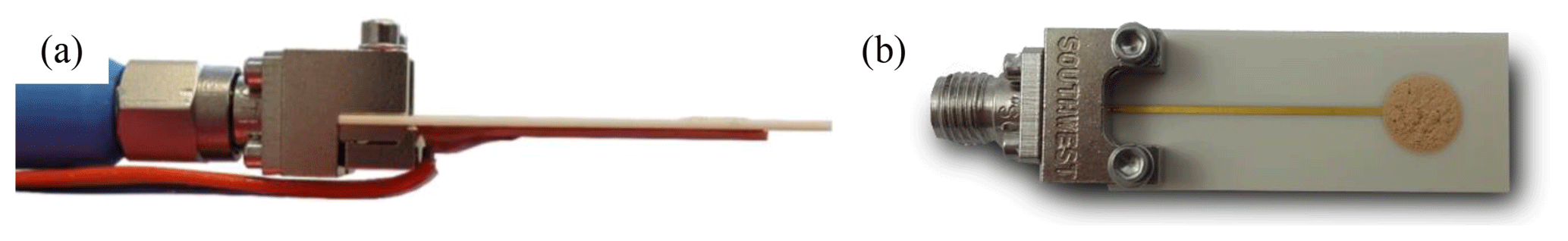
Figure 3Side (a) and top view (b) of the sensor with the iron zeolite layer above the resonance structure.
In order to determine the sensor behavior to different gases, it was installed in a glass chamber that can be flushed with various gas mixtures. Mass flow controllers allow defined concentrations of NH3, O2 and NO to be added to the N2 base gas. The total volume flow during the measurements was continuously 0.5 L min−1. The radio-frequency sensor was kept at a constant temperature by the integrated heating element. For this purpose, the dependency between the temperature of the sensitive layer and the heater resistance was determined before with a pyrometer outside of the glass chamber. Due to the risk of possible overheating of the installed SMA socket and the PTFE used in it, the sensor was operated at a maximum temperature of 300 ∘C in the area around the sensitive layer. Since therefore a temperature-based removal of the strongly bound ammonia in the zeolite was not possible, regeneration was done by purging the sensor with a nitrogen-oxide–oxygen mixture. As a result, the stored ammonia is converted to nitrogen and water by the standard SCR reaction (Koebel et al., 2000):
The frequency of the first resonant mode serves as the sensor signal. A vector network analyzer (Anritsu MS2820B) measures the magnitude of the reflection coefficient S11 in the range of 8 to 10 GHz approximately every 10 s. A Lorentz curve is fitted to these measured data. By means of the fit parameters, the resonant frequency, which corresponds to a minimum of the S11 coefficient can be determined. However, even with an unloaded zeolite a temperature dependence can be observed. This is caused by a changed resonance geometry due to the thermal expansion of the sensor as well as by the temperature-dependent permittivity of the sensor materials. In order to eliminate this cross-sensitivity to the sensor signal, only the relative frequency shift related to the resonant frequency of the unloaded sensor in a nitrogen atmosphere fr,0 will be considered.
After Bogner et al. (2017) has already shown that the sensor signal reacts sensitively to ammonia at room temperature, but is also strongly influenced by the water content of the gas atmosphere, the sensor is now operated at temperatures of over 100 ∘C to reduce its water adsorption capability of the zeolite (Srinivasan et al., 2017). Now, an investigation will be made into how ammonia is stored in the gas-sensitive zeolite layer and how this influences the resonance behavior of the sensor.
4.1 Temperature dependence of the ratio between strongly and weakly bound ammonia
First, the amount of strongly and weakly bound ammonia of the total sensor signal is to be determined in dependence of the temperature of the sensitive layer. For this purpose, the sensor was warmed up to temperatures between 200 and 300 ∘C by the integrated heater. First, an ammonia concentration of 500 ppm was adjusted for 10 min to a nitrogen atmosphere. The ammonia dosing was then switched off and the sensor chamber was purged with nitrogen for 20 min to enable the weakly bound ammonia to desorb. Finally, 500 ppm NO and 5 % O2 were added to remove the ammonia still stored in the sensor.

Figure 4Resonant frequency shift during adsorption as well as free and (by addition of NO) forced desorption of ammonia.
Figure 4 shows the measured relative resonant frequency shift during ammonia loading and unloading. At all considered temperatures, the resonant frequency decreases after ammonia has been added. According to Eq. (1), this is caused by an increase in the permittivity of the sensitive layer. Thus, these measurements are consistent with the results of previous research (Dietrich et al., 2017; Rauch et al., 2017). The increase in sensor temperature results in a significantly lower resonant frequency shift. While at 200 ∘C a gas phase concentration of 500 ppm NH3 leads to a change in the signal of 0.3 %, this decreases to 0.1 % at 300 ∘C. The reason for this is the reduced ammonia storage capacity of zeolites at higher temperatures (Rauch et al., 2015).
After switching off the ammonia dosing, a decrease of the sensor signal occurs immediately due to the release of weakly bound ammonia. Due to the temperature-dependent reaction kinetics, desorption takes place much faster at higher temperatures. Depending on the requirements, the radio-frequency sensor could be adjusted to a fast response to changes in ammonia concentration or to a high sensor signal by varying the operating temperature. Due to the strongly bound ammonia remaining in the sensitive layer, the same resonant frequency is not achieved at temperatures below 300 ∘C as before ammonia dosing started. After free desorption has been completed, a clear temperature dependency is still apparent. However, as soon as the nitrogen-oxide–oxygen mixture has been added, the strongly bound fraction can leave the zeolite through the SCR reaction (Eq. 2) and the sensor signal returns to its original level.
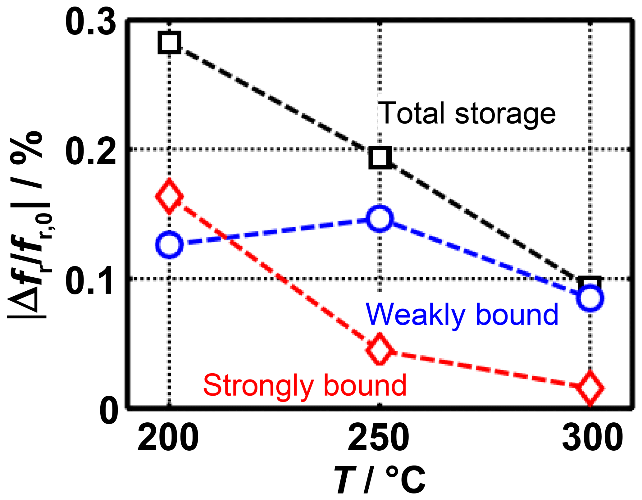
Figure 5Frequency shift caused by strongly and weakly bound ammonia at different sensor temperatures.
Just before the end of ammonia dosing and the free desorption, the total sensor signal as well as the signal caused by strongly bound ammonia can be determined. From the difference between the two values, it is possible to calculate the frequency shift caused by the weakly bound ammonia. These three values are shown in Fig. 5 as a function of the sensor temperature. This clearly shows that a major part of the temperature dependence of the total signal is caused by the strongly bound ammonia. The weakly bound ammonia, on the other hand, is only slightly affected by the temperature. For instance, at 300 ∘C the frequency shift during free desorption is almost completely decreased; at 200 ∘C, however, the signal is still higher than 50 % of the maximum value measured during the NH3 adsorption. This means that the radio-frequency sensor can be operated at temperatures at which it can be probably used as a gas sensor due to the insignificant influence of strongly bound ammonia.
4.2 Geometry optimization for operation at higher temperatures
As already mentioned in Sect. 3, to prevent possible overheating of the SMA connector, the sensor was only operated at temperatures up to 300 ∘C. Although the temperatures were sufficient to completely reduce the frequency signal to values before ammonia loading, an external addition of nitrogen oxides was necessary to ensure that the strongly bound ammonia was actually completely removed.
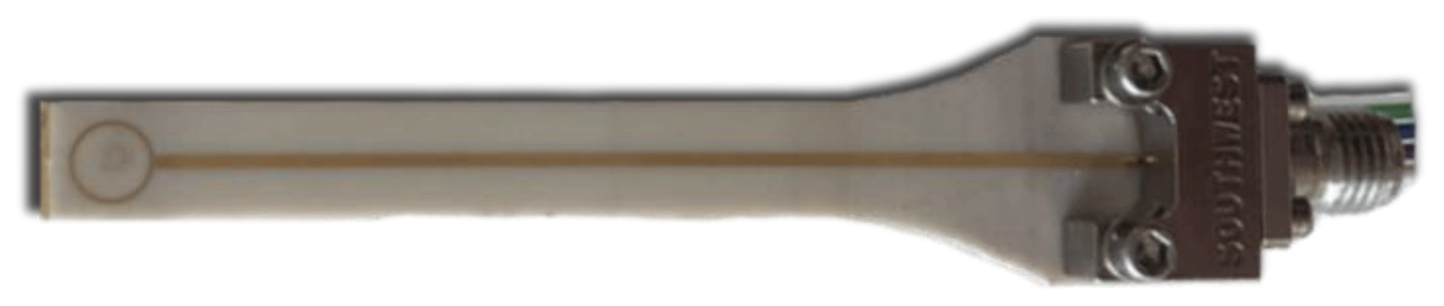
To avoid this in future work, significantly higher temperatures have to be made possible. In order to increase the thermal resistance between the sensitive layer and the radio-frequency connector, the carrier substrate geometry was adapted (Fig. 6). On the one hand, the width of the substrate in the area of the resonance structure was reduced to 6.35 mm. To enable the mounting of the SMA socket, the carrier substrate widens slightly to the connector end of the sensor. On the other hand, the length of the sensor has been extended to 60 mm. Hereby, the thermal resistance between the heated area of the sensor and the SMA socket could be increased considerably. Due to the resulting higher conductor losses of the longer excitation line and the resulting weaker sensor signal, the geometry of the resonance structure was also adapted by reducing the coupling gap width d from 150 to 75 µm.
To determine the maximum operating temperature of the new sensor design, the entry setup was thermally simulated with the FEM software COMSOL Multiphysics. The simulation model considered not only the heat conduction in the sensor and connector but also natural convection to the ambient air, thermal radiation and the electrical heating by the integrated heater. Forced convection by a flowing gas was not included. This however, would increase heat dissipation and thus enable a higher maximum operating temperature. Figure 7a shows the heat distribution at a sensor temperature of approx. 700 ∘C. Immediately behind the resonance structure, the temperature drops significantly. In stationary simulations, the connector temperature remains below 110 ∘C (Fig. 7b). These simulations could be validated at the produced sensors using a pyrometer. Therefore, damage to the SMA socket does not occur even after prolonged operation.
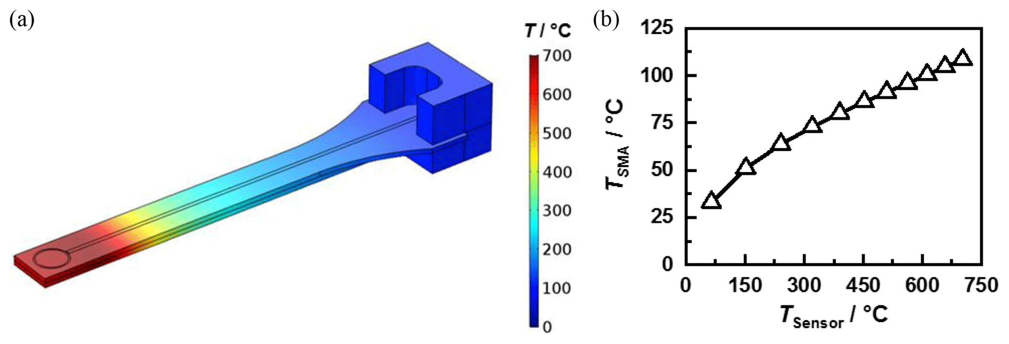
Figure 7(a) Simulated temperature distribution at a sensor temperature of approx. 700 ∘C. (b) Simulated temperature of the SMA connector TSMA depending on the temperature of the sensitive layer TSensor.
Before the behavior of the redesigned radio-frequency sensor is investigated in more detail with regard to possible gas sensor characteristics, the functionality and the reproducibility compared with the old sensor design should be checked first. For this purpose, the same experiment as described above and as shown in Fig. 4 was performed again in a temperature range from 100 to 300 ∘C (Fig. 8). However, the strongly bound ammonia was no longer desorbed by the external addition of NO but by heating the sensor up to 600 ∘C. Due to the adapted resonance geometry, an evaluation of the resonant frequencies was still possible without any problems.
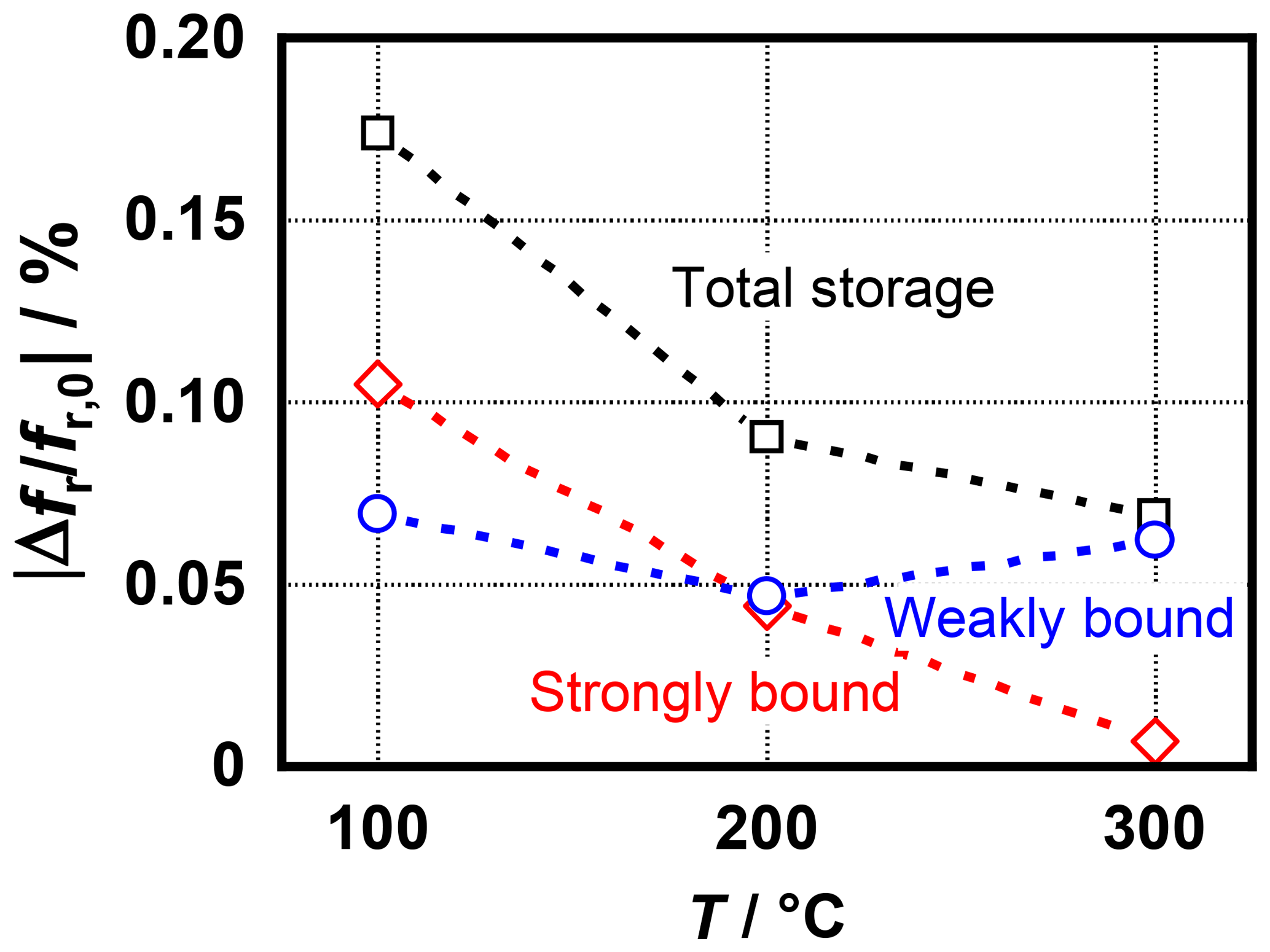
Figure 8Frequency shift caused by strongly and weakly bound ammonia at different sensor temperatures measured with the optimized sensor design.
Overall, the results are very similar to the previous sensor design. The weakly bound fraction remains almost constant over the entire temperature range, while the strongly bound fraction decreases continuously and has nearly no influence on the total sensor signal at 300 ∘C. However, compared with the previous design a weaker sensor signal is obtained. One reason for this may be the thickness of the sensitive layer, which was only reproducible in a limited extent due to the manual deposition of the zeolite paste. This could be considerably improved in future developments using screen printing technology.
4.3 Gas sensor behavior at higher temperatures
In order to prove that the sensor signal is also dependent on the ammonia concentration in the gas phase, a further measurement was carried out, at which the sensor was operated at a temperature of 310 ∘C. For this purpose, the sensor was exposed to an ammonia concentration of 100 ppm after a complete removal of the bounded ammonia and a short purging with nitrogen. After a stationary sensor signal had been reached, the gas phase concentration is gradually increased in steps of 100 ppm each up to a maximum of 500 ppm. The response time of the sensor until almost no change of the sensor signal occurred took approx. 1 min. After this, the ammonia dosage was switched off and the resonant frequency reached again the value before the start of dosage. This shows that at this sensor temperature no measurable amount of ammonia is strongly bound in the sensitive layer. Changes in the sensor signal are exclusively due to the storage of weakly bound ammonia.
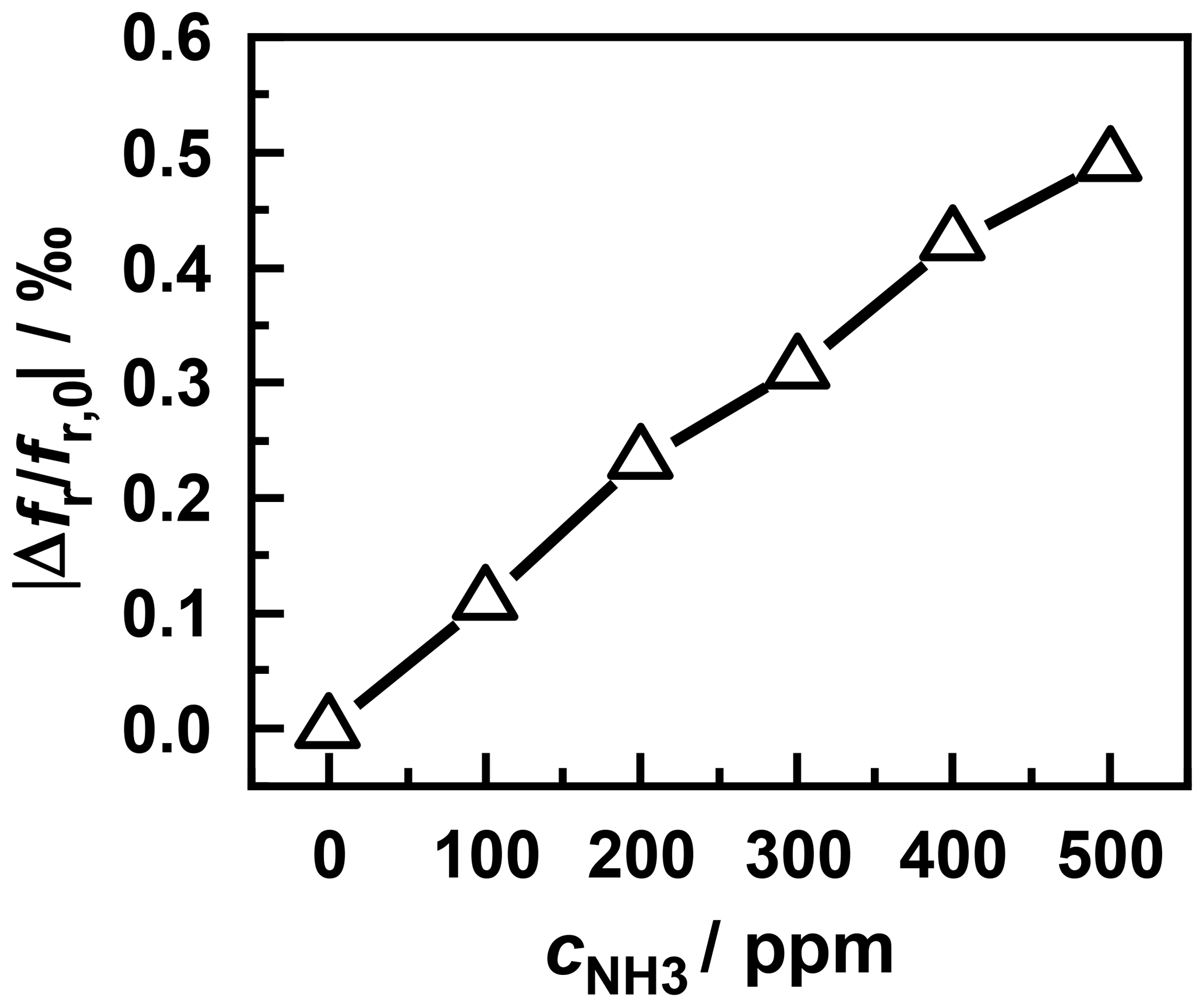
Figure 9Frequency shift caused by different ammonia concentrations at a sensor temperature of 310 ∘C.
Figure 9 shows the resonant frequency at the end of each desorption process (i.e., after a steady state has been reached) versus the ammonia concentration in the nitrogen base gas. Thereby, a linear characteristic of the sensor can be seen at the considered concentrations. Thus the measuring setup can be used as a gas sensor at temperatures above 310 ∘C. By increasing the sensor temperature further, the storage and desorption rate of ammonia could be enhanced, as shown by the measurement in Fig. 4. This might considerably shorten the response time of the sensor.
Previous planar radio-frequency sensors were only designed for operation at room temperature. In this work, the application of high-temperature active materials as the gas-sensitive layer was made possible for the first time with this sensor principle. For this purpose, a heating element was implemented in the sensor in such a way that the radio-frequency signal is not disturbed. Using FEM simulations, the geometry of the sensor substrate could be adapted in such a way that even during continuous operation at 700 ∘C in the area of the resonance structure, no damage to temperature-sensitive radio-frequency components will occur.
An Fe zeolite served as the sensitive layer for the first gas measurements, enabling the sensor to be used for ammonia detection. Depending on the operating temperature of the sensor, ammonia is bound differently in the sensitive layer. Thus, the amount of strongly bound ammonia, which remains in the layer even with decreasing partial pressure, drops with increasing temperature. At temperatures above 300 ∘C, only weakly bound ammonia has an effect on the sensor signal, which makes it possible to use the radio-frequency sensor for gas concentration measurements.
In further work, the radio-frequency sensor has to be characterized more precisely at operating temperatures that allow gas concentration measurement without the influence of strongly bound ammonia. Furthermore, the ability of the sensor for dosimetric detection of very low ammonia concentrations will also be evaluated. In addition, the use of various other sensitive materials with high temperature activity should be investigated. Possible applications include ceria for oxygen detection or materials that store nitrogen oxide, such as those used in NOx-storage catalysts.
All relevant data presented in the article are stored according to institutional requirements and as such are not available online. However, all data used in this paper can be made available upon request to the authors.
All authors planned the experiments. AB performed the experiments using the original sensor design. SW optimized the sensor and performed the experiments with the new sensor design. All authors evaluated the results and wrote the paper.
The authors declare that they have no conflict of interest.
This article is part of the special issue “Sensors and Measurement Systems 2018”. It is a result of the “Sensoren und Messsysteme 2018, 19. ITG-/GMA-Fachtagung”, Nürnberg, Germany, from 26 June 2018 to 27 June 2018.
The authors gratefully thank
Dr. Jaroslaw Kita for manufacturing the sensor substrates and
laser-patterning the microstrip
structures.
Edited by: Leonhard
Reindl
Reviewed by: two anonymous referees
Bailly, G., Harrabi, A., Rossignol, J., Stuerga, D., and Pribetich, P.: Microwave gas sensing with a microstrip interDigital capacitor: Detection of NH3 with TiO2 nanoparticles, Sens. Actuat. B, 236, 554–564, https://doi.org/10.1016/j.snb.2016.06.048, 2016a.
Bailly, G., Rossignol, J., de Fonseca, B., Pribetich, P., and Stuerga, D.: Microwave Gas Sensing with Hematite: Shape Effect on Ammonia Detection Using Pseudocubic, Rhombohedral, and Spindlelike Particles, ACS Sens., 1, 656–662, https://doi.org/10.1021/acssensors.6b00297, 2016b.
Barsan, N., Koziej, D., and Weimar, U.: Metal oxide-based gas sensor research: How to?, Sens. Actuat. B, 121, 18–35, https://doi.org/10.1016/j.snb.2006.09.047, 2007.
Beulertz, G., Votsmeier, M., and Moos, R.: Effect of propene, propane, and methane on conversion and oxidation state of three-way catalysts: a microwave cavity perturbation study, Appl. Catal. B, 165, 369–377, https://doi.org/10.1016/j.apcatb.2014.09.068, 2015.
Bogner, A., Steiner, C., Walter, S., Kita, J., Hagen, G., and Moos, R.: Planar Microstrip Ring Resonators for Microwave-Based Gas Sensing: Design Aspects and Initial Transducers for Humidity and Ammonia Sensing, Sensors, 17, 2422, https://doi.org/10.3390/s17102422, 2017.
Chahadih, A., Cresson, P. Y., Hamouda, Z., Gu, S., Mismer, C., and Lasri, T.: Microwave/microfluidic sensor fabricated on a flexible kapton substrate for complex permittivity characterization of liquids, Sens. Actuat. A, 229, 128–135, https://doi.org/10.1016/j.sna.2015.03.027, 2015.
Chang, K. and Hsieh, L.-H.: Microwave ring circuits and related structures, 2nd ed., Wiley-Interscience, Hoboken, NJ, 5–55, 2004.
Chen, L.: Microwave electronics: Measurement and materials characterization, Wiley, Chichester, 300–309, 2005.
Comini, E., Faglia, G., and Sberveglieri, G. (Eds.): Solid State Gas Sensing, Springer Science & Business Media LLC, Boston, MA, 2009.
Dietrich, M., Rauch, D., Simon, U., Porch, A., and Moos, R.: Ammonia storage studies on H-ZSM-5 zeolites by microwave cavity perturbation: Correlation of dielectric properties with ammonia storage, J. Sens. Sens. Syst., 4, 263–269, https://doi.org/10.5194/jsss-4-263-2015, 2015.
Dietrich, M., Steiner, C., Hagen, G., and Moos, R.: Radio-Frequency-Based Urea Dosing Control for Diesel Engines with Ammonia SCR Catalysts, SAE Int. J. Engines, 10, 1638–1645, https://doi.org/10.4271/2017-01-0945, 2017.
Di Iorio, J. R., Bates, S. A., Verma, A. A., Delgass, W. N., Ribeiro, F. H., Miller, J. T., and Gounder, R.: The Dynamic Nature of Brønsted Acid Sites in Cu–Zeolites During NOx Selective Catalytic Reduction: Quantification by Gas-Phase Ammonia Titration, Top. Catal., 58, 424–434, https://doi.org/10.1007/s11244-015-0387-8, 2015.
Hagen, G., Kita, J., Izu, N., Röder-Roith, U., Schönauer-Kamin, D., and Moos, R.: Planar platform for temperature dependent four-wire impedance spectroscopy – A novel tool to characterize functional materials, Sens. Actuat. B, 187, 174–183, https://doi.org/10.1016/j.snb.2012.10.068, 2013.
Hanft, D., Glosse, P., Denneler, S., Berthold, T., Oomen, M., Kauffmann-Weiss, S., Weis, F., Häßler, W., Holzapfel, B., and Moos, R.: The Aerosol Deposition Method: A Modified Aerosol Generation Unit to Improve Coating Quality, Materials, 11, 1572, https://doi.org/10.3390/ma11091572, 2018.
Hoefer, U., Steiner, K., and Wagner, E.: Contact and sheet resistance of SnO2 thin films from transmission-line model measurements, Sens. Actuat. B, 26, 59–63, https://doi.org/10.1016/0925-4005(94)01557-X, 1995.
Koebel, M., Elsener, M., and Kleemann, M.: Urea-SCR: a promising technique to reduce NOx emissions from automotive diesel engines, Catal. Today, 59, 335–345, https://doi.org/10.1016/S0920-5861(00)00299-6, 2000.
Kubinski, D. and Visser, J.: Sensor and method for determining the ammonia loading of a zeolite SCR catalyst, Sens. Actuat. B, 130, 425–429, https://doi.org/10.1016/j.snb.2007.09.007, 2008.
Ménil, F., Debéda, H., and Lucat, C.: Screen-printed thick-films: From materials to functional devices, J. Eur. Ceram. Soc., 25, 2105–2113, https://doi.org/10.1016/j.jeurceramsoc.2005.03.017, 2005.
Pozar, D. M.: Microwave Engineering, 4th ed., Wiley, Hoboken, NJ, 147–153, 2012.
Rauch, D., Dietrich, M., Simons, T., Simon, U., Porch, A., and Moos, R.: Microwave Cavity Perturbation Studies on H-form and Cu Ion-Exchanged SCR Catalyst Materials: Correlation of Ammonia Storage and Dielectric Properties, Top. Catal., 60, 243–249, https://doi.org/10.1007/s11244-016-0605-z, 2017.
Rauch, D., Kubinski, D., Cavataio, G., Upadhyay, D., and Moos, R.: Ammonia Loading Detection of Zeolite SCR Catalysts using a Radio Frequency based Method, SAE Int. J. Engines, 8, 1126–1135, https://doi.org/10.4271/2015-01-0986, 2015.
Rodríguez-González, L., Rodríguez-Castellón, E., Jiménez-López, A., and Simon, U.: Correlation of TPD and impedance measurements on the desorption of NH3 from zeolite H-ZSM-5, Solid State Ionics, 179, 1968–1973, https://doi.org/10.1016/j.ssi.2008.06.007, 2008.
Rossignol, J., Barochi, G., de Fonseca, B., Brunet, J., Bouvet, M., Pauly, A., and Markey, L.: Microwave-based gas sensor with phthalocyanine film at room temperature, Sens. Actuat. B, 189, 213–216, https://doi.org/10.1016/j.snb.2013.03.092, 2013.
Rydosz, A., Maciak, E., Wincza, K., and Gruszczynski, S.: Microwave-based sensors with phthalocyanine films for acetone, ethanol and methanol detection, Sens. Actuat. B, 237, 876–886, https://doi.org/10.1016/j.snb.2016.06.168, 2016.
Srinivasan, A., Joshi, S., Tang, Y., Wang, D., Currier, N., and Yezerets, A.: Development of a Kinetic Model to Evaluate Water Storage on Commercial Cu-Zeolite SCR Catalysts during Cold Start, SAE Tech. Pap., 2017-01-0968, https://doi.org/10.4271/2017-01-0968, 2017.
Zarifi, M. H., Thundat, T., and Daneshmand, M.: High resolution microwave microstrip resonator for sensing applications, Sens. Actuat. A, 233, 224–230, https://doi.org/10.1016/j.sna.2015.06.031, 2015.
Zarifi, M. H., Shariaty, P., Hashisho, Z., and Daneshmand, M.: A non-contact microwave sensor for monitoring the interaction of zeolite 13X with CO2 and CH4 in gaseous streams, Sens. Actuat. B, 238, 1240–1247, https://doi.org/10.1016/j.snb.2016.09.047, 2017.