Low Fatigue Dynamic Auxetic Lattices With 3D Printable, Multistable, and Tuneable Unit Cells
 Eesha Khare
 Stephen Temple1
  Ivan Tomov
 Fenghua Zhang
 Stoyan K. Smoukov
- 1Active and Intelligent Materials Lab, Department of Materials Science and Metallurgy, University of Cambridge, Cambridge, United Kingdom
- 2Centre for Composite Materials and Structures, Harbin Institute of Technology, Harbin, China
- 3Faculty of Chemistry and Pharmacy, University of Sofia, Sofia, Bulgaria
- 4School of Engineering and Materials Science, Queen Mary University of London, London, United Kingdom
Stress distribution has led to the design of both tough and lightweight materials. Truss structures distribute stress well and are commonly used to design lightweight materials for applications experiencing low strains. In 3D lattices, however, few structures allow high elastic compression and tunable deformation. This is especially true for auxetic material designs, such as the prototypical re-entrant honeycomb with sharp corners, which are particularly susceptible to stress concentrations. There is a pressing need for lightweight lattice designs that are dynamic, as well as resistant to fatigue. Truss designs based on hinged structures exist in nature and delocalize stress rather than concentrating it in small areas. They have inspired us to develop s-hinge shaped elastic unit cell elements from which new classes of architected modular 2D and 3D lattices can be printed or assembled. These lattices feature locally tunable Poisson ratios (auxetic), large elastic deformations without fatigue, as well as mechanical switching between multistable states. We demonstrate 3D printed structures with stress delocalization that enables macroscopic 30% cyclable elastic strains, far exceeding those intrinsic to the materials that constitute them (6%). We also present a simple semi-analytical model of the deformations which is able to predict the mechanical properties of the structures within <5% error of experimental measurements from a few parameters such as dimensions and material properties. Using this model, we discovered and experimentally verified a critical angle of the s-hinge enabling bistable transformations between auxetic and normal materials. The dynamic modeling tools developed here could be used for complex 3D designs from any 3D printable material (metals, ceramics, and polymers). Locally tunable deformation and much higher elastic strains than the parent material would enable the next generation of compact, foldable and expandable structures. Mixing unit cells with different hinge angles, we designed gradient Poisson's ratio materials, as well as ones with multiple stable states where elastic energy can be stored in latching structures, offering prospects for multi-functional designs. Much like the energy efficient Venus flytrap, such structures can store elastic energy and release it on demand when appropriate stimuli are present.
Introduction
Delocalization of stress is key to designing tougher materials, including nanomaterials (Chen et al., 2008), adhesives (Ausiello et al., 2002), and structures capable of repeated cycling deformation (Strnadel et al., 1995; Barthelat, 2007). Most strategies to improve fracture toughness are based on microstructural design, including addition of particles that redistribute stresses in a growing crack to prevent damage (Launey and Ritchie, 2009) or hierarchical structuring (Shin et al., 2016). Many of these strategies, including composites and complex architectures, have been demonstrated as proof-of-concept through 3D additive manufacturing (Dimas et al., 2013), which promises to revolutionize structural properties via complex material designs. However, many challenges remain that need to be solved for particular composite structures, materials, and printing techniques. 3D printing often results in defects and non-uniformities due to inter-layer adhesion inconsistencies and sharp corners, demonstrating an even greater need to have designs that help make materials flexible and repeatedly deformable.
Auxetic material designs, such as the re-entrant honeycomb with sharp corners, are particularly susceptible to stress concentrations. For a number of dynamic applications, it would be useful to have flexible versions of auxetic materials with tunable Poisson ratios, due to their remarkable ability to change their volume under tension or compression, increased shear stiffness, and synclastic curvature (Lakes, 1987, 1992, 1993a; Evans and Alderson, 2000a,b; Alderson and Alderson, 2007; Grima and Caruana-Gauci, 2012; Mir et al., 2014; Mizzi et al., 2014). Their unusual macroscopic properties of expanding in the lateral direction when stretched and accompanying shape changes enable their use in a range of applications, from bioengineering stents to polymeric filters to mechanical energy storage, which require the structure to be able to move repeatedly without failure (Alderson et al., 2001; Ali and Rehman, 2011). Some natural materials are also auxetic and demonstrate these unusual properties through well-known mechanisms involving negative pressures and tension (Boal et al., 1993; Wojciechowski, 1995). Other auxetic designs include re-entrant units (Gibson et al., 1982), chiral structures (Lakes, 1991; Prall and Lakes, 1997), interconnected polymeric nodules (Evans, 1989), or relative rotation of rigid units, such as squares, rectangles or triangles (Grima et al., 2005; Espinosa et al., 2011). Such designs are not always amenable to 3D printing, however, and in addition, stress concentrations at nodes and rigid beam elements limit their elastic deformation range and cycling capabilities. More flexible auxetic structures include polymeric foams or composite laminates, yet these lack a uniform periodic structure, making it difficult to analyze and improve their properties (Friis et al., 1988; Milton, 1992; Lakes, 1993b, 1996; Choi and Lakes, 1996; Yeh et al., 1999; Sigmund, 2000; Lakes and Wojciechowski, 2008; Schwerdtfeger et al., 2011; Andreassen et al., 2014). Research on controllable and tunable periodic materials and structures with negative Poisson's ratio is still nascent (Bückmann et al., 2012; Shufrin et al., 2012; Babaee et al., 2013; Clausen et al., 2015; Shan et al., 2015b), with researchers developing planar isotropic structures based on elongated cuts (Shan et al., 2015b), rigid cores surrounded by hexagonal flexible frames (Shufrin et al., 2012), periodic distributions of monodisperse holes to induce buckling (Shim et al., 2013), translational cubic lattices (Bückmann et al., 2014), and origami tessellations (Silverberg et al., 2014; Christensen et al., 2015). Novel designs and methods are needed for enabling improved elastic cycling performance, rapid manufacturability, and larger mechanical energy storage of real auxetic structures.
In this work, we report a new class of high-strain, tunable 2D and 3D auxetic materials enabled by a smooth hinge geometry design, in place of the straightedge solid rib connections in conventional reentrant honeycombs. The s-shaped hinge design minimizes stress concentration by distributing strain and stress through the length of the hinge, thus enabling repeated elastic compression to strains greater than those of which the parent material is capable. Further, the ability to vary the hinge arc allows one to vary its Poisson's ratio properties for the same unit cell, yielding a critical bistable angle that transitions from positive to negative Poisson's ratio. Finally, the greater flexibility of the design enables a multistable latch-release structure to be developed in which orthogonal actuation and release of the latch storage mechanism have advantages compared to current bistable storage mechanisms with high-stress concentration (Shan et al., 2015a).
Materials and Methods
3D Printing
Samples were manufactured using fused deposition modeling, a facile extrusion-based 3D printing technique. In this widely available technique, thermoplastic polymers are extruded in a layer-by-layer manner on a heated plate. The standard MakerBot Replicator was used as the desktop 3D printer and 1.75 mm diameter polylactic acid (PLA) filament was extruded through a tapered nozzle. These viscoelastic filament polymers exhibit shear-thinning behavior that enables facile extrusion from the nozzle and subsequent cooling into the desired structure on the print bed. A heated build plate was used in conjunction with a 50 micron layer of Kapton® tape to improve the adhesion of the printed filament to the build plate. Figure S1A demonstrates the 3D printing set up used in this study.
The samples were designed using SketchUp, a freely available 3D modeler, and written into a stereolithography file format (STL), which specifies tool path, print speed, retraction amount, and other factors that influence print quality. To create the 3D structure, models were made by printing unit strips of multiple cells and then solvent welding them together to form an interdigitated 3D material.
Mechanical Characterization
For load-displacement measurements, a Tinius Olsen benchtop Hounsfield 5 kN tension-compression machine with a 250 N load cell was used. The specimens were compressed using flat aluminum plates under quasi-static conditions at a rate of 1 mm/min. To enable lateral movement of the samples due to auxetic property, the samples were lubricated with oil. It was found that this lubrication reduced the friction at the sample edges, and by comparing the experimental force-displacement results with the analytical equations, the reduced coefficient of static friction was found to be 0.2556.
In our tests, the samples were not attached to the compression plates. As a result, in some of the measurements, there is a brief nonlinearity before the elastic response in the force-displacement curve. This nonlinearity is not present in each measurement and indicates the brief change in contact between the sample and the compression plate. Each test was repeated multiple times and the results were in good agreement, demonstrating good repeatability.
To characterize the Poisson's ratio, the inwards movement of markers placed at the ends of the auxetic samples were measured as the samples were compressed a predetermined amount.
Finite Element Simulations
The commercial finite element (FE) software ABAQUS (SIMULA, version 6.14) was used for the simulation of the elastic and plastic responses in the auxetic models. 3D FE models were constructed by importing AutoCAD drawing exchange format models of the auxetic into ABAQUS and using element type CPE6MH and each instance was seeded to an “Approximate global size” 1.
The response of the material was captured using a linear elastic model with PLA filament values reported in literature; a Young's modulus of 3500 MPa and Poisson's ratio of 0.36 (Tymrak et al., 2014). These values were used both in this finite element simulation and in the analytical calculations.
We applied a boundary condition of a downward 20 mm movement to one edge of the auxetic. This set simulated the movement of the compression plates in our force-displacement testing. The bottom edge of the structure was constrained with an ENCASTRE constraint to prevent vertical or horizontal movement, simulating the stationary bottom edge during the force-displacement testing.
In each simulation, the spatial displacement and reaction force in the relative x or y direction was monitored at the centralized reference point. This resulted in the simulation force-displacement curves shown above. Poisson's ratios were extracted in a similar manner by monitoring the displacement of the edges of the structure.
The finite element simulation accurately models the elastic region of the auxetic deformations. Figures 2A,B demonstrates the comparison between the experimental and simulation results. As depicted for both the honeycomb and the s-hinged auxetic deformed in the straight-edge direction, the simulation is in agreement with the experimental data until the yield point of PLA.
Results and Discussion
S-Shape Hinge
The novel stress-delocalization design was inspired by a smooth hinge geometry in nature, which minimizes stress concentration by distributing it through the length of the hinge. We applied the concept to replace the straight edges of the conventional reentrant honeycomb with optimally deforming redesigned arcs between the solid ribs (Figure 1A). These arcs were calculated with an appropriate radius and arc length that enable the greatest range of deformation, while staying within the elastic limit of PLA printer filament, and exhibit a much larger range of deformation compared to the conventional honeycomb (Figures 1B,C).
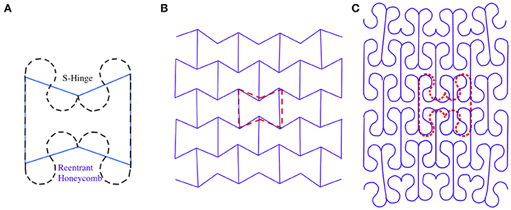
Figure 1. Fabrication of s-hinged unit cell into a 2D and 3D auxetic material. (A) S-hinged unit cell (dashed) overlaid on comparison of a reentrant honeycomb unit cell (solid blue). (B) Compressed reentrant honeycomb auxetic with outline of original cell, stresses concentrate at vertices. (C) Compressed s-hinged auxetic (made from 225-degree arc length) with outline of original cell, stresses distribute with deformation of the whole hinge.
To illustrate the benefits of this new auxetic design, we also fabricated a conventional auxetic honeycomb structure with the same unit cell size and reentrant angle for valid comparison. We note that this 3D printing procedure is particularly well suited to demonstrate advantages of our s-hinge geometric design because common defects, such as rounded corners or poorly connected nodes that occur when using one continuous filament to print sharp edges, are prevented by printing the curved structure.
Stress Distribution in S-Hinge Structure
We combined experimental testing and finite element (FE) simulations to determine both the macroscopic and local stress and strain behavior in the s-hinge compared to the conventional honeycomb.
The experimental and FE models are in good agreement (Figures 2A,B), showing that the model faithfully captures the physics of the deformation. In the conventional reentrant honeycomb, stress is concentrated at the corners of the honeycomb, limiting macroscopic elastic deformation to only 3%. At this strain the local von Mises stress in the joint corners reaches the critical stress of 54 MPa for PLA (Figure 2C) (Tymrak et al., 2014). In contrast, the s-hinge structure delocalizes the stress concentration, reaching a maximum local von Mises stress of 8 MPa at that same macroscopic compression (Figure 2D). This delocalization of stress enables a larger elastic macroscopic strain for the structure, increasing from 3% in the conventional honeycomb to 30% for the s-hinged auxetic. The s-hinge structure also enables a lower equivalent plastic strain (Figure S3).
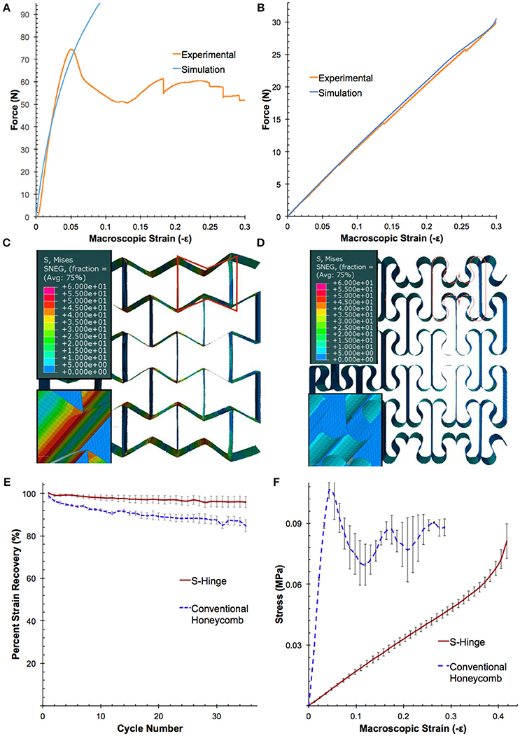
Figure 2. Experimental and FE simulation characterization of conventional honeycomb and s-hinge auxetics. The good agreement of results from the experimental and FE simulations for the (A) conventional honeycomb and (B) s-hinge structures validate the finite element models developed for the structures. The FE simulations are accurate within the elastic region of deformation (local stress < 57.8 MPa). When both structures are deformed elastically to 3% macroscopic strain, finite element analysis demonstrates that stress (color legend numbers in MPa) is (C) unevenly concentrated in the joints of the honeycomb, reaching a maximum of 58 MPa in the corners, and (D) uniformly distributed along the length of the s-hinge at 1 MPa. The orange outline represents the original undeformed cell. (E) Fatigue testing of auxetic materials over 35 cycles of macroscopic 7% strain demonstrates that the s-hinged auxetics have a far greater strain recovery after multiple cycles of loading and unloading compared to the conventional honeycomb structure. (F) Macroscopic strain vs. stress curve for the conventional honeycomb and s-hinge, depicted until the macroscopic strain limit of the s-hinge structure.
This stress and strain minimization through the s-hinge design allows a wider range of materials to be used for the auxetic structure. For a 10% macroscopic strain of the structure, one achieves a maximum of 0.70% logarithmic strain locally, which is within the elastic limit of a wider range of materials. This property of the s-hinged structure would enable more materials, such as glass fibers, ceramics, and other brittle materials with small elastic regions that were previously difficult to apply in auxetic geometries, to be used as auxetics, while still achieving a large macroscopic reversible strain.
To investigate how this increased elastic range of the s-hinged auxetic would affect repeated cyclability, we carried out fatigue testing to determine strain recovery after cycling both structures to 7% macroscopic strain, which falls within the elastic region of the s-hinged structure and the plastic region of the conventional honeycomb (Figure 2E). Plastic deformation, even in the absence of a large deviation from elastic behavior, leads to damage and its effects can be seen upon repeated compressive cycling. After 35 cycles, the s-hinge is able to recover nearly all of its strain (96%), while the conventional honeycomb only recovers to 85%, demonstrating the benefit of increased elastic macroscopic deformation gained from the s-hinged structure.
Deformation Characterization of S-Hinge Structure
The stress versus strain curve in Figure 2F summarizes the mechanical behavior of the two geometries in compression, for which our structure is optimized. The initial linear region in both curves demonstrates the structure's elastic regime. The conventional honeycomb is much stiffer and quickly reaches its elastic limit, where the sharp peak denotes plastic collapse of the beams and the subsequent spikes show softening and hardening of the structure that occur during the breaking and collapse of different sets of beams. In contrast to this behavior, the much larger apparently elastic region of the s-hinge structure extends up to 33% macroscopic strain, compared to 3% in the conventional honeycomb. We note that for extending these principles to extension, one should smoothen the connection where the s-hinges meet with the straight-edge linking segments. Though not in the scope of this work, introducing another smooth joint would only increase the design complexity somewhat, yet could prevent stress concentration in tension as well. Additional improvements, as beautifully shown by Masoumi Khalil Abad et al. (2012), could be made by providing smoothening through G2 continuity though here the choice was made to keep the structural elements simple for the purpose of both design and analytical calculations.
When loaded along the direction of the rigid ribs, the force-displacement curve closely matches that of the honeycomb characterized by Gibson et al. in their seminal work on this type of structure (Figure 3A, Movie S1) (Gibson et al., 1982). In the first region up to 5% macroscopic strain, the deformation is elastic and reversible. In this region, the edges transverse to the direction of compression contract inwards, demonstrating auxetic behavior. Upon further compression, the structure exhibits buckling, during which the planes of the honeycombs slip in opposite directions. This slipping of the rigid straight edges results in a metastable state with plane dislocations caused by shear stress and enables a large deformation at a nearly constant load. At the end of this plateau region, continued loading reaches contact between elements leading to densification of the structure, increasing the macroscopic “solid-like” stress, but also coupled with plastic irreversible yielding deformations as well. In this region, load required for further deformation increases rapidly as the opposing cell walls impinge upon one another.
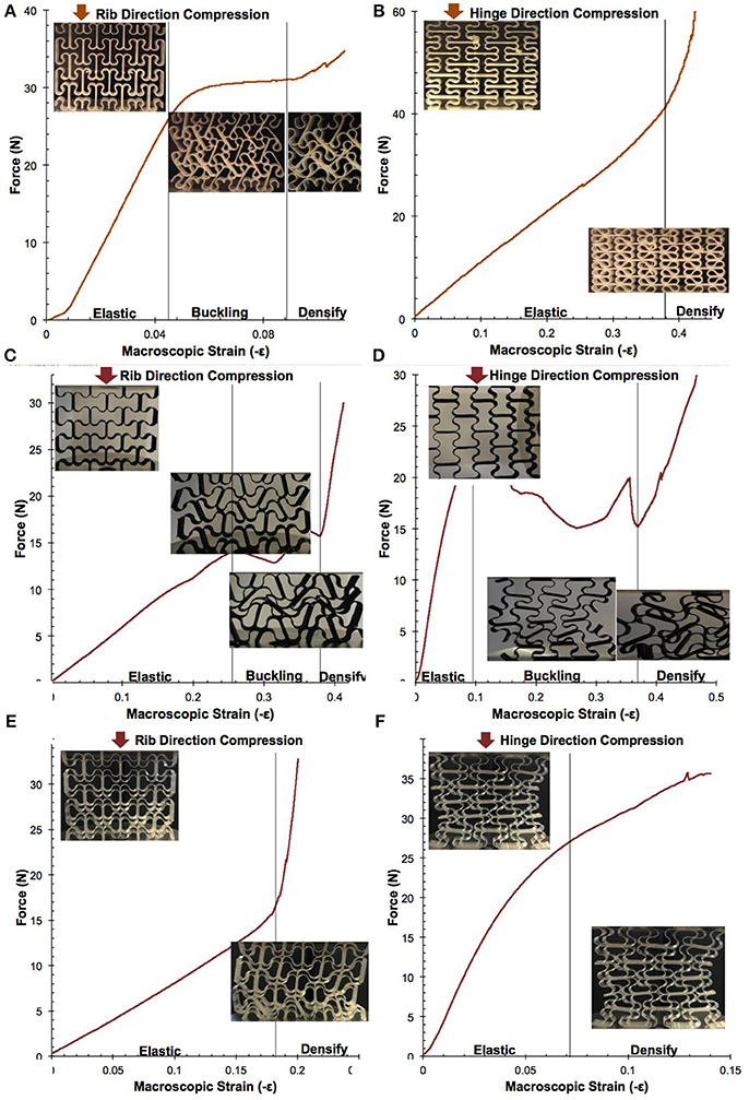
Figure 3. Force-displacement characterization of s-hinged auxetic deformed in the rigid rib and hinged directions. For the s-hinged auxetic, (A) compression along the rigid rib direction results in a linear region up to 5% strain, then an in-plane buckling / slipping of unit rows in opposite directions, and finally densification after contacting neighboring elements, and (B) compression along the hinge direction results in a nearly-linear behavior. The 160-degree single s-hinge structure compressed in the (C) rib and (D) hinge direction experiences an elastic, buckling, and densification region. The double s-hinge structure compressed in the (E) rib direction and (F) hinge direction, transitions directly from the linear deformation region to the high stress region where elements come in contact, eliminating the in-plane (nonmonotonic) buckling region observed in the single s-hinge structure.
When loaded along the direction of the hinges, the force-displacement curve displays a behavior where the deformation pattern goes directly from the elastic region to densification (Figure 3B, Movie S2). The geometry of structure enables the force to be evenly transferred along the s-hinge and thus deform nearly-linearly without plane dislocations.
In contrast to the conventional honeycomb where densification occurs unevenly throughout the structure (Figure S4), densification occurs uniformly in both loading directions of the s-hinge. We note that this stress-strain profile for the 3D printed s-hinged auxetic closely matches that of less well-defined open-cell polyurethane foams currently researched as isotropic auxetics, and could improve our understanding of their behavior, including the change to a quasi-exponential stress-strain curve (Cadamagnani et al., 2009). This deformation behavior can be tuned by changing the arc angle of the s-hinge, in a controllable manner similar to that shown for kagome lattices (Wu et al., 2015). By changing the arc angle, the macroscopic strain and position at which the first row begins to buckle changes (Figure S5).
To demonstrate how the deformation of these structures can be tuned, we designed a double s-hinge structure (Figure 3E, inset). The double s-hinge rigidifies the structure to inhibit lateral movement of the unit cells. Figures 3C,D show the three deformation regions of the 160-degree single s-hinge structure. The introduction of extra hinges limits the amount of linear elastic deformation one could achieve before contact with neighboring elements. The double hinge structure (Figures 3E,F) has significantly higher stress for the same macroscopic strain and deforms monotonically from the elastic to the densifying deformation region. This has the added benefit of avoiding the buckling instability modes present in the single hinge, leading to higher predictability of stress at high strain deformations in this structure.
Parametric Numerical Modeling to Predict Deformation Behavior
We developed a parametric numeric model and incorporated the samples' dimensions and materials properties to predict elastic deformation and Poisson's ratios of the s-hinged structures (Figure 4A). The methods used in this semi-analytical model are applicable to a wider range of complex initial geometries and force applications.
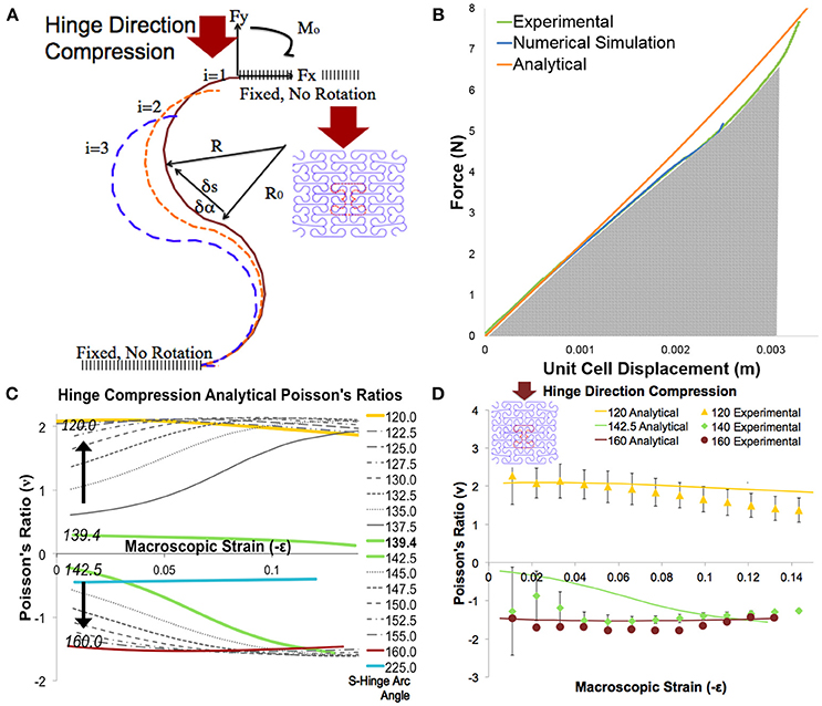
Figure 4. Analytical and experimental Poisson's ratios. (A) Schematic from the mathematical model that demonstrates variables involved in calculation of the bending movement. (B) The semi-analytical model is in good agreement with the experimental results and numerical simulation when the 225-degree deformed in the hinge direction. (C) Poisson's ratio is sensitive to the change in arc-angle near the critical arc angle of 139.4 degrees. 225-degree Poisson's ratio also displayed (blue line). (D) Poisson's ratio can be tuned by changing the s-hinge arc angle. Experimental Poisson's ratios (data points) are compared to Poisson's ratios computed analytically (solid lines) when compressed along the hinge direction.
To begin our model, we assumed bending deformation as the primary method of deformation during compression of the structure. In conventional beam bending analysis, the beam is assumed to be straight initially. However, for an initially curved beam, there is a change in radius from the initial shape
where Ro is the initial radius curvature and R is the subsequent radius of curvature.
Our analytical calculation is additionally complicated by the axial application of force. In conventional analysis, the beam experiences a transverse force. In our buckling calculations however, the axial force application results in a bending moment that depends upon the local deflected shape of the beam, yielding a complex relationship. By combining these two conditions together—the initial curved structure and axially applied force—the simple analytical solution yields accurate predictions for the experimental stress-strain relations.
Using Microsoft Excel, we developed an iterative system of analytical formulas, which use the initial curved structure of the beam to calculate where it moves upon applying an incremental force. The deflections of the beam can be calculated by using an intrinsic relationship between the length along the curved beam, s, and the tangential angle, α,
By using an incremental form of this relationship, we carried out a finite integration of the deflection of the beam and iterated to find the appropriate fixed end moments. The ends of the beam are constrained not to rotate, as in our physical model the hinges are constrained by the rigid ribs. Therefore, the fixed end moments are found by applying an incremental force less than 10% of the maximum compressive force
where M0 is the bending moment at the start of the curve, Fy is the force applied in the hinge direction, Fx is the force applied in the rib direction, X and Y are coordinates of the curve, and the primary index i represents the time step and the secondary index n represents the position along the curve. For the fixed end moments, n = 1, the end position of the hinge.
Using the fixed end moments, moments along the remainder of the beam are calculated, used to find the change in radius of curvature, and used to find the next position. This process is repeated several times to yield the deformation of the hinge over several applied forces (Figure 4A), resulting in a force-displacement curve. The remainder of the model is presented in the supplementary information.
This semi-analytical model closely matches the experimental and numerical simulation data in the elastic deformation region (95% accuracy for a 10% unit cell strain) and provides a powerful way to generalize the behavior of an s-hinged unit cell (Figure 4B). Further, the analytically predicted Poisson's ratios match with the experimental Poisson's ratios for the double s-hinge structures (Figure 4D). The maximum achievable negative Poisson's ratio from this structure is −1.5 when compressed along the hinge direction. With this model, we easily obtain the effect of changing beam thicknesses, structure size, or hinge arc angle on the stress-strain curves of the structure.
Using the deformation ratios found in the analytical model, we discovered a critical arc-angle of 139 degrees in the s-hinge, at which point the structure can achieve bistable transformations between auxetic and non-auxetic states. The structure designed with this critical angle exhibits close to zero Poisson's ratio with axial load, but upon application of a transverse load, it can switch between states with either negative or positive Poisson's ratio (Movie S3). Above a 139 degree arc angle, the structure has a negative Poisson's ratio and below, it has a positive one (Figure 4C). This critical behavior is remarkably similar to that exhibited by the Venus Fly Trap where a minimal transverse energy input results in a large deformation snap-through. Using the analytical model we can tune the energy barriers for switching between different structures, with small orthogonal stimuli.
Poisson's Ratio Measurements in 3D
The s-hinged design was easily assembled into 3D structures. For demonstration purposes, a 3D 160-degree s-hinged auxetic was designed and printed as a rectangular prism of 4 × 4 × 3 unit cells and a unique x-axis direction (Figure 5a) and Poisson's ratios were measured as a function of strain when compressed along each of the three different axes (Figure S1C). The Poisson's ratios are negative upon compression in each direction and can be tuned by changing the arcs on the unit cells making up the structure. When compressed along the x-axis near-symmetrical contraction was achieved along two 4 × 3 faces as expected, and the Poisson's ratio changes from approximately −0.5 to −1 depending on strain (Figure 5b). Upon compression along the different y- and z-axes, the Poisson's ratio changes from approximately −0.5 to −0.2 (Figure 5b). Because the rigid ribs of the unit cells are connected both axially and transversely to their neighboring unit cells, the 3D structure is very robust and exhibits near uniformity without plane dislocations upon compression, eliminating rotations associated with buckling in the 2D auxetics, while maintaining easy cyclability.
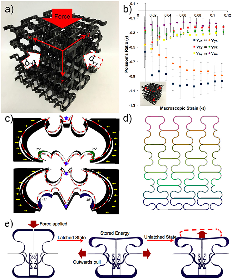
Figure 5. 3D auxetic structure and Poisson's ratio tunability and multistability. (a) 4 × 4 × 3 160-degree s-hinge 3D auxetic. Diagram shows force applied along the z-axis, and displacements along x and y. (b) Poisson's ratio for 3D s-hinged auxetic as a function of macroscopic strain in all directions are negative. Legend notation: the first letter is the transverse and the second is the axial axis along which the structure is compressed where the Poisson's ratio νyz = –dyz/dForce. (c) Poisson's ratio can be tailored by changing only the arc angle of the hinge, as illustrated by the arcs of the body and the tail connecting to the wings in the Batman logo. The top (original) Batman logo is not auxetic, but it becomes so when you change from the green arc (75 degree arc angle) to the blue arc (45 degree arc angle), the bottom dashed red line. (d) S-hinge can be developed into a gradient auxetic with changing arc angles and thus continuously tunable Poisson's ratios. (e) The multistable auxetic unit cell in relaxed/expanded state can be pushed down to yield a latched state that stores elastic energy in the absence of an external force. The latched state can be released by pulling open the transverse ledges, making use of the anisotropic auxetic properties of the structure.
To demonstrate the control of deformation our s-hinge structure enables, we varied arc-angles in a 3D printed Batman logo outline, which has curves similar to the critical angles we discovered in our unit cell (Figure 5c). While the original Batman logo (top), has a positive Poisson's ratio when compressed at the wings, a slight change of arc angle in the bottom re-designed logo makes it auxetic (see Movie S4). Such materials would lead to novel functionalities, such as designed shape-change upon mechanical compression. This tunability also enables the development of gradient auxetics (Figure 5d) where Poisson's ratio can be varied continuously throughout the structure by changing arc angles in neighboring cells. Changing the Poisson's ratio within a structure is useful for shape morphing structures with specific localized responses.
Multistable Auxetic Structures
The greater elastic deformation region of the s-hinge design also enabled us to develop a latching mechanism to capture and store elastic mechanical energy within the auxetic (Figure 5e, Movie S5), previously a challenging task, due to increasing stress concentrations in the conventional honeycomb. This demonstrated multistable auxetic latch is the first of its kind and yields a number of benefits including its lack of reliance on traditional mechanisms of multistability such as beam buckling or origami folding (Shan et al., 2015a; Waitukaitis et al., 2015), which could lead to plastic deformation, lack of control, and failure. It is also able to store several levels of elastic energy in multiple configurations via its layer-by-layer latching in a larger structure. Upon using a small force to pull the rigid ribs in the transverse direction, the latch is released. The energy held in a single unit cell during the latching process was calculated to be 39 J kg−1 PLA upon latching to a 15% unit cell strain, possible because of the s-hinge structure. While this number is modest, it can be greatly increased by designing much smaller unit cells with thinner ribs, where uniform deformation would lead to a larger fraction of the material at the surface of the ribs being strained near its elastic limit, instead of being constrained to the center of thick beams with little deformation. After optimization, such uniform, directional auxetic cell materials could be used for convenient elastic energy storage. The resulting latch structure can also be applied to other auxetic structures and, given appropriate miniaturization, authors propose using such a structures in multistable auxetic filters where several stable pore sizes could be selected and locked by directional compression.
Such latching and elastic storage mechanisms have wide uses in nature. Prominent examples include not only the Venus flytrap above, but also structures on the tendons of owls, eagles and other birds of prey which produce a fierce ratcheting, yet do not have to continually tense their muscles to keep the grip tight (Einoder and Richardson, 2007). Similar locking of joints in insects enable the extraudinary jumping ability of fleas (Sutton and Burrows, 2011) and froghoppers (Burrows, 2003) to generate forces up to 135 and 414 times their body weight respectively upon unlocking the joints (Burrows, 2003).
Conclusion
This paper demonstrates a novel s-hinged unit cell structural design that distributes stress and results in 3D printable structures more flexible than the building material. This approach presents a number of benefits including increased maximum elastic strain and the ability to tune the material's Poisson's ratio. A parametric, semi-analytical model was developed to predict the mechanical behavior of the new modular materials and its predictions successfully compare with experiments and finite element modeling. It is a powerful tool for the prediction and design of novel auxetics and custom deformation ratio materials. The insights gained from this paper would enable parametric design of gradient and shape-changing materials and allow their incorporation into practical, 3D printable components today. Further, we demonstrate bistable geometries that can easily switch between negative and positive Poisson's ratios, and a latch mechanism enabling multistability and elastic energy storage, which can be released on demand by a small tensile transverse force. Bioinspiration from fleas and the ratcheting claws of raptors could be combined with our designs capable of high elastic strain and energy storage without fatigue. Thus one could envision whole classes of new smart materials that could store energy in the absence of external forces, and release that energy upon sensing of multiple stimuli, leading to a type of material robotics.
Author Contributions
SS and EK conceived and designed the study. EK performed designs and experiments. ST designed the flexible hinge and the analytical simulation model. IT helped with 3D printing and numerical simulations. FZ helped with printing and mechanical tests. EK wrote the first draft and all authors contributed to writing the paper.
Funding
This work was funded by the European Research Council (ERC) grant EMATTER (#280078) and the Harvard-Cambridge Summer Fellowship. FZ would also like to thank Chinese Scholarship Council (CSC) for funding her research work at the University of Cambridge.
Conflict of Interest Statement
The authors declare that the research was conducted in the absence of any commercial or financial relationships that could be construed as a potential conflict of interest.
Supplementary Material
The Supplementary Material for this article can be found online at: https://www.frontiersin.org/articles/10.3389/fmats.2018.00045/full#supplementary-material
References
Masoumi Khalil Abad, E., Pasini, D., and Cecere, R. (2012). Shape optimization of stress concentration-free lattice for self-expandable Nitinol stent-grafts. J. Biomech. 45, 1028–1035. doi: 10.1016/j.jbiomech.2012.01.002
Alderson, A., and Alderson, K. (2007). Auxetic materials. Proc. Inst Mech. Eng. G J. Aerospace Eng. 221, 565–575. doi: 10.1243/09544100JAERO185
Alderson, A., Rasburn, J., Evans, K., and Grima, J. (2001). Auxetic polymeric filters display enhanced de-fouling and pressure compensation properties. Membr. Tech. 2001, 6–8. doi: 10.1016/S0958-2118(01)80299-8
Ali, M. N., and Rehman, I. (2011). An Auxetic structure configured as oesophageal stent with potential to be used for palliative treatment of oesophageal cancer; development and in vitro mechanical analysis. J. Mater. Sci. Mater. Med. 22, 2573–2581. doi: 10.1007/s10856-011-4436-y
Andreassen, E., Lazarov, B., and Sigmund, O. (2014). Design of manufacturable 3D extremal elastic microstructure. Mech. Mater. 69, 1–10. doi: 10.1016/j.mechmat.2013.09.018
Ausiello, P., Apicella, A., and Davidson, C. (2002). Effect of adhesive layer properties on stress distribution in composite restorations—a 3D finite element analysis. Dent. Mater. 18, 295–303. doi: 10.1016/S0109-5641(01)00042-2
Babaee, S., Shim, J., Weaver, J., Chen, E., Patel, N., and Bertoldi, K. (2013). 3D soft metamaterials with negative poisson's ratio. Adv. Mater. 25, 5044–5049. doi: 10.1002/adma.201301986
Barthelat, F. (2007). Biomimetics for next generation materials. Philos. Trans. A Math. Phys. Eng. Sci. 365, 2907–2919. doi: 10.1098/rsta.2007.0006
Boal, D. H., Seifert, U., and Shillcock, J. (1993). Negative Poisson ratio in two-dimensional networks under tension. Phys. Rev. E 48, 4274–4283. doi: 10.1103/PhysRevE.48.4274
Bückmann, T., Schittny, R., Thiel, M., Kadic, M., Milton, G., and Wegener, M. (2014). On three-dimensional dilational elastic metamaterials. New J. Phys. 16:033032. doi: 10.1088/1367-2630/16/3/033032
Bückmann, T., Stenger, N., Kadic, M., Kaschke, J., Frölich, A., Kennerknecht, T., et al. (2012). Tailored 3D mechanical metamaterials made by dip-in direct-laser-writing optical lithography. Adv. Mater. 24, 2710–2714. doi: 10.1002/adma.201200584
Cadamagnani, F., Frontoni, S., Bianchi, M., and Scarpa, F. (2009). Compressive uniaxial properties of auxetic open cell PU based foams. Physica Status Solidi 246, 2118–2123. doi: 10.1002/pssb.200982044
Chen, A., Li, D., Zhang, J., Song, H., and And Lu, J. (2008). Make nanostructured metal exceptionally tough by introducing non-localized fracture behaviors. Scr. Mater. 59, 579–582. doi: 10.1016/j.scriptamat.2008.04.048
Choi, J., and Lakes, R. (1996). Fracture toughness of re-entrant foam materials with a negative Poisson's ratio: experiment and analysis. Int. J. Fracture 80, 73–83. doi: 10.1007/BF00036481
Christensen, J., Kadic, M., Kraft, O., and Wegener, M. (2015). Vibrant times for mechanical metamaterials. MRS Commun. 5, 453–462. doi: 10.1557/mrc.2015.51
Clausen, A., Wang, F., Jensen, J., Sigmund, O., and Lewis, J. (2015). Topology optimized architectures with programmable poisson's ratio over large deformations. Adv. Mater. 27, 5523–5527. doi: 10.1002/adma.201502485
Dimas, L., Bratzel, G., Eylon, I., and Buehler, M. (2013). Tough composites inspired by mineralized natural materials: computation, 3D printing, and testing. Adv. Funct. Mater. 23, 4629–4638. doi: 10.1002/adfm.201300215
Einoder, L., and Richardson, A. (2007). The digital tendon locking mechanism of owls: variation in the structure and arrangement of the mechanism and functional implications. EMU 107, 223–230. doi: 10.1071/MU06019
Espinosa, H. D., Juster, A., Latourte, F., Loh, O., Gregoire, D., and Zavattieri, P. (2011). Tablet-level origin of toughening in abalone shells and translation to synthetic composite materials. Nat. Commun. 2:173. doi: 10.1038/ncomms1172
Evans, K. (1989). Tensile network microstructures exhibiting negative Poisson's ratios. J. Phys. D Appl. Phys. 22, 1870–1876. doi: 10.1088/0022-3727/22/12/011
Evans, K., and Alderson, A. (2000a). Auxetic Materials: functional materials and structures from lateral thinking!. Adv. Mater. 12, 617–628. doi: 10.1002/(SICI)1521-4095(200005)12:9<617::AID-ADMA617>3.0.CO;2-3
Evans, K., and Alderson, K. (2000b). Auxetic materials: the positive side of being negative. Eng. Sci. Edu. J. 9, 148–154. doi: 10.1049/esej:20000402
Friis, E., Lakes, R., and Park, J. (1988). Negative Poisson's ratio polymeric and metallic foams. J. Mater. Sci. 23, 4406–4414. doi: 10.1007/BF00551939
Gibson, L., Ashby, M., Schajer, G., and Robertson, C. (1982). The mechanics of two-dimensional cellular materials. Proc. R. Soc. A Math. Phys. Eng. Sci. 382, 25–42. doi: 10.1098/rspa.1982.0087
Grima, J., Alderson, A., and Evans, K. (2005). Auxetic behaviour from rotating rigid units. Physica Status Solidi 242, 561–575. doi: 10.1002/pssb.200460376
Grima, J. N., and Caruana-Gauci, R. (2012). Materials that push back. Nat. Mater. 11, 565–566. doi: 10.1038/nmat3364
Lakes, R. (1987). Foam structures with a negative Poisson's ratio. Science 235, 1038–1040. doi: 10.1126/science.235.4792.1038
Lakes, R. (1991). Deformation mechanisms in negative Poisson's ratio materials: structural aspects. J. Mater. Sci. 26, 2287–2292. doi: 10.1007/BF01130170
Lakes, R. (1993a). Advances in negative Poisson's ratio materials. Adv. Mater. 5, 293–296. doi: 10.1002/adma.19930050416
Lakes, R. (1996). Re-entrant transformation methods in closed cell foams. Cell Polymers 15, 229–249.
Lakes, R., and Wojciechowski, K. (2008). Negative compressibility, negative Poisson's ratio, and stability. Physica Status Solidi 245, 545–551. doi: 10.1002/pssb.200777708
Launey, M., and Ritchie, R. (2009). On the fracture toughness of advanced materials. Adv. Mater. 21, 2103–2110. doi: 10.1002/adma.200803322
Milton, G. (1992). Composite materials with poisson's ratios close to-−1. J. Mech. Phys. Solids 40, 1105–1137. doi: 10.1016/0022-5096(92)90063-8
Mir, M., Ali, M., Sami, J., and Ansari, U. (2014). Review of mechanics and applications of auxetic structures. Adv. Mater. Sci. Eng. 2014, 1–17. doi: 10.1155/2014/753496
Mizzi, L., Attard, D., Casha, A., Grima, J., and Gatt, R. (2014). On the suitability of hexagonal honeycombs as stent geometries. Physica Status Solidi 251, 328–337. doi: 10.1002/pssb.201384255
Prall, D., and Lakes, R. (1997). Properties of a chiral honeycomb with a poisson's ratio of-−1. Int. J. Mech. Sci. 39, 305–314. doi: 10.1016/S0020-7403(96)00025-2
Schwerdtfeger, J., Wein, F., Leugering, G., Singer, R., Körner, C., Stingl, M., et al. (2011). Design of auxetic structures via mathematical optimization. Adv. Mater. 23, 2650–2654. doi: 10.1002/adma.201004090
Shan, S., Kang, S., Raney, J., Wang, P., Fang, L., Candido, F., et al. (2015a). Multistable architected materials for trapping elastic strain energy. Adv. Mater. 27, 4296–4301. doi: 10.1002/adma.201501708
Shan, S., Kang, S., Zhao, Z., Fang, L., and Bertoldi, K. (2015b). Design of planar isotropic negative Poisson's ratio structures. Extrem. Mech. Lett. 4, 96–102. doi: 10.1016/j.eml.2015.05.002
Shim, J., Shan, S., Košmrlj, A., Kang, S., Chen, E., Weaver, J., et al. (2013). Harnessing instabilities for design of soft reconfigurable auxetic/chiral materials. Soft Matter 9, 8198–8202. doi: 10.1039/c3sm51148k
Shin, Y. A., Yin, S., Li, X., Lee, S., Moon, S., Jeong, J., Kwon, M., Yoo, S., Kim, Y., Zhang, T., et al. (2016). Nanotwin-governed toughening mechanism in hierarchically structured biological materials. Nat. Commun. 7:10772. doi: 10.1038/ncomms10772
Shufrin, I., Pasternak, E., and Dyskin, A. (2012). Planar isotropic structures with negative Poisson's ratio. Int. J. Solids Struct. 49, 2239–2253. doi: 10.1016/j.ijsolstr.2012.04.022
Sigmund, O. (2000). A new class of extremal composites. J. Mech. Phys. Solids 48, 397–428. doi: 10.1016/S0022-5096(99)00034-4
Silverberg, J. L., Evans, A., McLeod, L., Hayward, R., Hull, T., Santangelo, C., et al. (2014). Using origami design principles to fold reprogrammable mechanical metamaterials. Science 345, 647–650. doi: 10.1126/science.1252876
Strnadel, B., Ohashi, S., Ohtsuka, H., Miyazaki, S., and Ishihara, T. (1995). Effect of mechanical cycling on the pseudoelasticity characteristics of TiNi and TiNiCu alloys. Mater. Sci. Eng. A 203, 187–196. doi: 10.1016/0921-5093(95)09881-X
Sutton, G. P., and Burrows, M. (2011). Biomechanics of jumping in the flea. J. Exp. Biol. 214, 836–847. doi: 10.1242/jeb.052399
Tymrak, B., Kreiger, M., and Pearce, J. (2014). Mechanical properties of components fabricated with open-source 3-D printers under realistic environmental conditions. Mater. Des. 58, 242–246. doi: 10.1016/j.matdes.2014.02.038
Waitukaitis, S., Menaut, R., Chen, B., and van Hecke, M. (2015). Origami multistability: from single vertices to metasheets. Phys. Rev. Lett. 114:055503. doi: 10.1103/PhysRevLett.114.055503
Wojciechowski, K. (1995). Negative Poisson ratios at negative pressures. Mol. Phys. Rep. 10, 129–136.
Wu, G., Cho, Y., Choi, I., Ge, D., Li, J., Han, H., et al. (2015). Directing the deformation paths of soft metamaterials with prescribed asymmetric units. Adv. Mater. 27, 2747–2752. doi: 10.1002/adma.201500716
Keywords: auxetic, 3D printing, multistability, stress distribution, tunable
Citation: Khare E, Temple S, Tomov I, Zhang F and Smoukov SK (2018) Low Fatigue Dynamic Auxetic Lattices With 3D Printable, Multistable, and Tuneable Unit Cells. Front. Mater. 5:45. doi: 10.3389/fmats.2018.00045
Received: 25 February 2018; Accepted: 12 July 2018;
Published: 09 August 2018.
Edited by:
Brahim Aissa, MPB Technologies and Communications, CanadaReviewed by:
Lihua Jin, University of California, Los Angeles, United StatesAdnan Ali, Qatar Foundation, Qatar
Copyright © 2018 Khare, Temple, Tomov, Zhang and Smoukov. This is an open-access article distributed under the terms of the Creative Commons Attribution License (CC BY). The use, distribution or reproduction in other forums is permitted, provided the original author(s) and the copyright owner(s) are credited and that the original publication in this journal is cited, in accordance with accepted academic practice. No use, distribution or reproduction is permitted which does not comply with these terms.
*Correspondence: Stoyan K. Smoukov, s.smoukov@qmul.ac.uk