
Abstract
For a successful implementation of newly proposed silicon-based latent heat thermal energy storage systems, proper ceramic materials that could withstand a contact heating with molten silicon at temperatures much higher than its melting point need to be developed. In this regard, a non-wetting behavior and low reactivity are the main criteria determining the applicability of ceramic as a potential crucible material for long-term ultrahigh temperature contact with molten silicon. In this work, the wetting of hexagonal boron nitride (h-BN) by molten silicon was examined for the first time at temperatures up to 1750 °C. For this purpose, the sessile drop technique combined with contact heating procedure under static argon was used. The reactivity in Si/h-BN system under proposed conditions was evaluated by SEM/EDS examinations of the solidified couple. It was demonstrated that increase in temperature improves wetting, and consequently, non-wetting-to-wetting transition takes place at around 1650 °C. The contact angle of 90° ± 5° is maintained at temperatures up to 1750 °C. The results of structural characterization supported by a thermodynamic modeling indicate that the wetting behavior of the Si/h-BN couple during heating to and cooling from ultrahigh temperature of 1750 °C is mainly controlled by the substrate dissolution/reprecipitation mechanism.
Introduction
Silicon is the main material used upon a large scale fabrication of photovoltaic devices, MEMS systems or diode temperature sensors (Ref 1, 2). Very recently (Ref 3, 4), molten silicon has been also proposed as particularly interesting phase change material for ultrahigh temperature latent heat thermal energy storage (LHTES) applications, due to its extraordinarily high latent heat (1800 J/g) and high melting point (1414 °C). In the view of this new application it is also a matter of crucial importance to establish reliable data on thermophysical properties of silicon in both solid and liquid states, particularly at temperatures much higher than its melting point. Nevertheless, most of measurement techniques (e.g., thermogravimetry, dilatometry or differential scanning calorimetry) are container-assisted. A high reactivity of silicon with refractory materials may lead to either a questionable credibility of obtained results or even to a severe damage of apparatus. Thus, in the case of both LTHES applications and analyses taken at such high temperatures, a selection of proper container/crucible material is a challenging task.
Generally, the two main requirements for crucible materials are (1) a negligible reactivity to avoid contamination of the material and to increase the crucible lifetime, and (2) a non-wetting behavior (the contact angles much higher than 90°) in contact with a molten material to avoid liquid metal penetration inside a crucible resulting in its degradation (Ref 5).
The problem of reactivity and wettability of molten silicon with ceramic refractory materials has been so far widely analyzed mostly concerning a melting-assisted fabrication of ultrahigh purity solar grade silicon (Ref 6,7,8). The following ceramics have been analyzed as potential crucible materials in this field and corresponding working conditions below 1500 °C:
-
(1)
Ionocovalent oxides (e.g., silica, alumina, magnesia) (Ref 6);
-
(2)
Graphite where wetting is assisted by the reactive infiltration process leading to a formation of silicon carbide (Ref 7);
-
(3)
Predominantly covalent ceramics (SiC, Si3N4, AlN, h-BN) (Ref 8).
It has been established that a high affinity of silicon to oxygen, nitrogen and carbon is basically responsible for its wetting with almost most of commonly used in practice ceramics. The contact angle θ values of silicon at temperatures slightly higher than its melting point on ionocovalent oxides and nitrides as well as on carbon substrates are close to or lower than 90º (Ref 6,7,8). It was recognized that the involved mechanism of interaction between molten silicon and ionocovalent oxides (Al2O3, SiO2, MgO, ZrO2) is based on a partial dissolution of a substrate, leading to the oversaturation of the melt with oxygen followed by reprecipitation of SiO2 product at the interface during cooling (Ref 8). The only exception among all examined Si/ceramic systems is hexagonal boron nitride (h-BN), a ceramic for which non-wetting behavior of Si is observed up to 1500 °C (Ref 8,9,10,11,12).
Despite a prominent scatter of reported values (originating from using of various testing apparatus, conditions or substrate materials) the θ for Si/h-BN couples at temperatures of 1420-1500 °C is within the range of 95°-145° corresponding to the non-wetting behavior (Ref 9,10,11,12). Possible mechanisms of the wetting/reactivity in this system were detailed discussed by Drevet et al. (Ref 12). They showed that under conditions of flowing argon, the contact angle of silicon on h-BN substrate at 1430 °C decreases from an initial value of 133° to a steady contact angle of 117° in about 10 min. This value did not change upon a further holding for 60 min. The proposed explanation for this finding was that the initial value of 133° corresponds to the contact angle of Si on the unreacted BN, while the observed spreading kinetics is controlled by the involved interface modification leading to the formation of discontinuous Si3N4 layer (having a thickness of ~ 10 µm). However, since the equilibrium contact angle θ f of Si on bulk Si3N4 substrate measured by the same team using the same testing procedure (Ref 12) is much lower (~ 49°) than that of the Si/h-BN couple, this mechanism brings some discrepancies. Therefore, Drevet et al. (Ref 12) formulated the hypothesis that at temperature of 1430 °C, the chemical equilibrium (a saturation of B in liquid Si) is established well before the equilibrium contact angle on the reaction product (Si3N4) layer is obtained.
Similar conclusions were also drawn by Yuan et al. (Ref 6), who also believed that a discontinuous Si3N4 layer (with a thickness below 20 µm) is formed at the Si/h-BN substrate interface during wettability tests at 1420 °C (under argon flow atmosphere), which might prevent BN from dissolving into molten silicon.
Nevertheless, most of the experimental data are reported for the Si/h-BN couples held at temperatures near the melting point of silicon. In fact, there are no reported data on wettability/reactivity of any silicon/ceramic couple at temperature higher than 1500 °C. Thus, the findings established in already reported works cannot be directly transferred or extrapolated to the present consideration of using h-BN as a crucible/container material both for measurements of thermophysical properties of Si-based alloys and for applications in LHTES devices at temperatures much higher than the melting point of Si. Therefore, the main purpose of the present work is to experimentally evaluate for the first time the reactivity and wettability of the Si/h-BN couple at temperature up to 1750 °C.
Materials and Methods
In the present study, a high purity silicon and commercially available h-BN sinters were used for sessile drop wettability test. The selected silicon material was amorphous polysilicon from the commercial Siemens process, which is applied for producing Si feedstock for electronic and solar industry. This ultrahigh purity silicon with purity above 7 N is precipitated from high purity silane (SiH4) or trichlorosilane (HSiCl3) gases at elevated temperatures (Ref 13). Commercially available hot isostatically pressed hexagonal boron nitride substrates (Henze HeBoSint® D100, Germany) were also used. The content of trace elements in investigated h-BN substrates was analyzed by using LECO CS600 Sulfur and Carbon content analyzer (combustion infrared detection technique) and by LECO TCH600-Nitrogen/Oxygen/Hydrogen Determinator (non-dispersive infrared and thermal conductivity techniques). The determined content of trace elements in h-BN substrates in as-received state was C: 0.101 ± 0.046, O: 1.590 ± 0.398 and S: 0.014 ± 0.003 wt.%. Small cubic pieces (3 × 3 × 3 mm3) were cut from Si polycrystals by a Struers Accutom-100 precise metallographic cutter equipped with a diamond wheel. Directly before loading in a vacuum chamber, each surface of Si piece was gently ground on SiC paper in order to remove SiO2 layer, then ultrasonically cleaned with isopropanol and dried. The h-BN substrates in as-received state were cut on plates with diameter of Ø17 mm and height of 4 mm. The contact surface of h-BN substrate before the test was subjected to a gentle mechanical polishing on a piece of office paper in order to obtain the initial surface roughness of r a ~ 150 nm (the surface profile was measured by NT-MDT NTEGRA Spectra scanning probe microscope—results are not shown in the paper). Contrary to previous reports (Ref 6, 8, 12), diamond paste was not used at any stage of polishing of h-BN substrates.
The wetting tests were performed by using an experimental complex described in details elsewhere (Ref 14). The wetting test was carried out by a sessile drop technique coupled with a contact heating procedure, i.e., the ultrahigh purity silicon piece (with the initial mass of m 0 ~ 50 mg) was placed on the h-BN substrate and then the Si/h-BN couple was subjected to the following heating/cooling procedure:
-
(1)
A preheating at 150 °C/16 h in a load lock chamber (in order to remove residual gases);
-
(2)
A slow heating with a rate of 10 °C/min from room temperature to 500 °C;
-
(3)
A fast heating with a rate of 15 °C/min from 500 to 1450 °C;
-
(4)
Five intervals of isothermal heating (steps—Fig. 1): 1450 °C/5 min (1); 1550 °C/5 min (2); 1650 °C/5 min (3); 1700 °C/5 min (4); 1750 °C/10 min (5);
Fig. 1 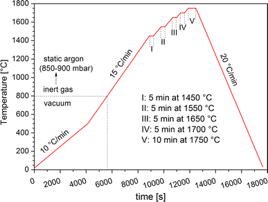
The heating/cooling scheme (a temperature profile) used upon the wetting test of Si/h-BN couple (atmosphere: vacuum of p = 1 × 10⁻⁶ mbar; argon: p = 850-900 mbar)
-
(5)
A cooling from 1750 °C to room temperature with a rate of 20 °C/min.

The test was carried out at high vacuum conditions (p = 1 × 10⁻⁶ mbar) at temperature up to 800 °C, and for higher temperatures the inert gas (static argon, p = 850-900 mbar) was introduced to the chamber in order to suppress the evaporation of silicon. During the wettability test, the images of the drop/substrate couples were recorded with a rate of 100 frames per second by using MC1310 high-speed high-resolution camera. The acquired images were used for a computation of the contact angle θ values with ASTRA2 [IENI-CNR, Italy (Ref 15)] special software as well as for preparing a real-time movie from high-temperature test (Supplementary data).
After the test, the solidified couple was removed from the chamber and then subjected to structural evaluations. The characterization was carried out by using FEI Scios™ field emission gun scanning electron microscope (FEG SEM) coupled with energy-dispersive x-ray spectroscopy (EDS). The instrumental hardness in microregions of cross-sectioned solidified couple was examined by using Anton Paar UNHT device equipped with Vickers-type diamond indenter working under a maximum loading force of 0.1 N and a loading rate of 0.20 N min−1.
Additionally, experimental results were supported by a thermodynamic assessment of phase stability and involved reactions taking place in the considered Si-B-C-N system by using FACT/FactSage 7.1 thermochemical software database. Thermodynamic descriptions of liquid and solid solution phases of the system were taken from the FTlite database. Thermodynamic properties of pure substances including gas species were adopted from the FactPS database.
Results and Discussion
Wetting and Spreading Behavior
A fast-forward video from the wettability test is presented as Supplementary data 1. It should be noted that during the whole test the liquid drop showed a non-stable behavior. A substantial vibration of the drop (i.e., oscillations of the triple line) was recorded both upon heating up and cooling down steps. This effect was more pronounced at temperatures T > 1650 °C. Kanai et al. (Ref 16) observed a similar behavior of the Si drop upon high-temperature wettability tests of Si/SiO2 couples. The authors concluded that the Si drop vibration on SiO2 substrate is the direct effect of formation, accumulation and release of SiO gaseous product. On the other hand, regarding the lack of reactively formed gaseous products in the Si/h-BN system, it is highly probable that the presently observed drop vibration comes from some other reasons. It was originally proposed by Champion et al. (Ref 17) that the oscillation of triple line during high-temperature expositions should be discussed in terms of the combined effects of evaporation, chemical reactivity and interfacial tensions in the system. The authors pointed out that this phenomenon comes from two contradicted effects taking place at the same time: (1) a substrate dissolution and (2) an evaporation of liquid metal combined with a formation of volatile oxide. Consequently, both of them lead to an observation of apparent contact angles—the former results with decreased values, while the latter with increased ones. Thus, it seems that in the present case the drop vibration might originate from a partial dissolution of substrate and oversaturation of molten silicon with nitrogen (through solid and liquid state diffusion) at high temperatures, followed by its release through liquid/gas and liquid/solid interfaces.
Wetting Kinetics
The wetting kinetic plot θ t = f(t) calculated for heating up to 1750 °C is presented in Fig. 2. Four stages (I-IV) may be distinguished on the obtained curve:

The wetting kinetic plot calculated for the sessile drop experiment of the Si/h-BN couple
Stage I
After melting, the Si sample formed a symmetrical drop shape at 1420 °C with corresponding contact angle of θ 1420 = 129°. During further heating up to 1450 °C for 220 s, the contact angle values rapidly decreased to θ 1450 = 116°. This result is very similar to that described by Drevet et al. (Ref 12) showing the decrease of θ 1430 = 133° to θ 1430 = 117° upon holding of Si/h-BN couple at 1430 °C for 600 s. As it has been already mentioned in the Introduction section, Drevet et al. concluded that this spreading behavior comes from the change in chemistry of liquid Si reacting with the substrate (i.e., its saturation in B) preceding the formation of Si3N4 interfacial product layer. This proposed mechanism will be later discussed in the view of our experimental results (see section 3.3).
Stage II
The contact angle was maintained at the level of 115° during further heating up to 1550 °C. Almost constant θ value and its relatively small variations at this temperature range point toward achieving chemical and thermodynamic equilibrium between involved solid/liquid/gaseous phases. Similar non-wetting behavior in the Si/h-BN system was reported previously at 1500 °C with corresponding equilibrium contact angle of 105° (Ref 10).
Stage III
At temperatures of 1550-1650 °C, a prominent decrease of contact angle values to non-wetting-to-wetting transition accompanied with the drop vibration and consequent scattering in the contact angle values (θ ~ 90° ± 5°), was observed. This behavior may be attributed to a further change in a liquid drop chemistry due to an increased dissolution of the h-BN substrate coming from:
-
(1)
An increase of boron and nitrogen solubility in liquid Si It has been already documented that with raising temperature of long-term annealing of Si/h-BN system in the range of 1420-1500 °C, the fraction of nitrogen dissolved in silicon increases from 25 to 67 ppma, while the boron fraction—from 137 to 173 ppma (Ref 18). It might be expected that this trend is also maintained at higher temperatures. Furthermore, while the solubility of B in liquid Si at T = 1550-1650 °C is quite high (between 21 and 30 at.%—according to Si-B binary phase diagram (Ref 19), the estimated solubility limit of N at this temperature range is drastically lower and not higher than 0.0002 at.% (Ref 20). Additionally, it was also documented that the presence of boron in liquid Si reduces the nitrogen content (Ref 20). Therefore, it might be stated that during this stage of high-temperature interaction, the liquid Si is gradually enriched in boron dissolved from the substrate, while the overbalanced nitrogen is released at the liquid/gas interface.
-
(2)
A start of degradation of boron nitride lattice by the formation of nitrogen vacancies at high temperature (Ref 21) This phenomenon presents an additional factor that facilitates substrate dissolution and enhances diffusion of B and N.
Stage IV
The contact angle was maintained at the level of 90° during further heating up from 1650 to 1750 °C. Once again, this plateau-like appearance of θ t = f(t) curve points toward an achievement of equilibrium conditions in the system. However, a very wide scatter of recorded θ values was measured due to the substantial drop vibration. As it has been already discussed in section 3.1, this behavior should be associated with the intensification of processes leading to the change in liquid metal chemistry and especially with the involvement of gaseous product action. It is also reasonable to assume that the intensive triple line oscillations come from a saturation of liquid Si with nitrogen, followed by its release at the liquid/gas interface. Additionally, with increase in temperature the effect of silicon evaporation should be also taken into account.
Additionally, a wetting-to-dewetting transition of Si droplet was recorded during the cooling, since the θ increased from ~ 90° ± 3° (at 1750 °C) to θ = 100° ± 3° after a full solidification. Interestingly, the solidification started at T = 1390 °C and was completed at T = 1356 °C. Both lowering temperatures of the solidification onset and a relatively wide temperature range of the phenomena point toward a change in chemistry of the initially pure Si toward the Si-based alloy. However, the possible effect of melt under cooling on these T values should be also taken into account. One of the dewetting models proposed by Zemskov (Ref 22), that might be used to clarify the behavior recorded for the Si/h-BN system in this work, assumes an involvement of residual gases action. This model is based on releasing a previously dissolved gases (here—nitrogen) at the solid–liquid interface. The gas is released at the solidification front, then transferred to the periphery by involving diffusion and capillary convection, followed by its ejection in the gap formed between solidified metal (here—Si crystal) and the substrate (here—h-BN). This model seems to be also in a good agreement with our previous discussion regarding wetting behavior of the couple.
Reactivity in Si/h-BN System at Temperatures up to 1750 °C: A Microstructural Characterization of the Solidified Couple
The reactivity in the Si/h-BN system was evaluated by macroscopic observations and SEM/EDS analyses taken on both top-view and cross-sectioned interface area.
The macroscopic top-view images of the Si/h-BN couple before and after the wettability test are shown in Fig. 3. The macroscopic observations revealed three main findings:

Macroscopic top-view images of the Si/h-BN couple before (on the left) and after (on the right) the high-temperature test at temperature up to 1750 °C (the secondary electron SEM insert shows the dewetting zone)
-
(1)
A color changeover from initially white to yellowish took place after the high-temperature exposition;
-
(2)
A formation of dewetting zone was observed;
-
(3)
The existence of ring surrounding the solidified drop is clearly distinguished.
We suggest that the color changeover of h-BN substrate after wettability test might be related with a slight change in its structure and chemistry since, as documented by Eichler and Lesniak (Ref 21), a degradation of h-BN lattice during heating in an inert atmosphere starts around 1500 °C. The electroparamagnetic resonance measurements coupled with thermogravimetric analyses carried out by Eichler and Lesniak (Ref 21) for the h-BN samples heat-treated up to 1800 °C in argon atmosphere, have evidenced that the degradation of the BN lattice takes place through the formation of nitrogen vacancies, and is also reflected by the change in optical appearance (from white to yellowish).
The results of a more detailed SEM evaluations (Fig. 4) show a well-defined h-BN platelets-like morphology within the dewetting zone. This area was covered by a molten silicon during the test at high temperature, and then it was revealed through a dewetting movement of the drop upon the cooling step. Furthermore, the existence of numerous spherical particles (mostly containing Si—as indicated by the results of EDS analyses, Fig. 4c) in this zone should be related to the effect of the formation of fine (having diameter of 2-5 µm) “daughter” droplets being left on the h-BN platelets after the movement of the “mother” Si drop. A rounded shape of Si daughter droplets also gives a proof that they did not wet the surface of h-BN platelets. This also means that h-BN platelets were not covered by any continuous wettable product layer. It was also documented by Liang et al. (Ref 23) that the obtained high surface roughness of platelets-like morphology additionally increases the non-wettability of h-BN (making it even “superhydrophobic”), as compared to counterparts having flat polished surfaces. What should be also noted, we did not observe any traces of Si3N4 product, neither as a discontinuous layer nor as precipitates, in this area. A strikingly different appearance of the dewetting zone as compared to the neighboring region (that was not subjected to a direct contact with molten Si—Fig. 5a) allows concluding that h-BN platelets were grown through a substrate dissolution/reprecipitation mechanism, similar to that already reported for many metal/borides, metal/carbides and metal/oxide systems (see, e.g., Ref 24,25,26,27,28). This high-temperature behavior of Si/h-BN couple is schematically shown in Fig. 6.

SEM/EDS examinations of the dewetting area observed from the top of solidified Si/h-BN couple taken at (a) a low magnification; (b) a higher magnification. (c) Results of the EDS mapping showing a high Si content in small droplet-like particles being left on the h-BN platelets after the “dewetting movement” of the mother Si drop

SEM images taken on the area located in the vicinity of the dewetting zone observed from the top of solidified Si/h-BN couple taken at (a) a low magnification; (b)-(d) a higher magnification

Real-time video images and a schematic drawing showing a wettability behavior of the Si/h-BN couple and the formation of h-BN platelets-like within the dewetting zone
The substrate surface area located next to the dewetting zone and limited by a ring surrounding the solidified drop seems to be free of any new products—as indicated by SEM images taken at low magnifications (Fig. 5a). However, at higher magnifications (Fig. 5b-d) the presence of very fine particles and few interconnected spider web-like features was documented.
With increasing the distance from the drop (i.e., going outside the ring limited area), a number of these spider web-like features significantly increased (Fig. 7a), covering almost whole remained surface of the h-BN substrate. Their morphology was prominently differentiated (Fig. 7b-d) with a length up to 20-30 µm and a thickness ranging from several to few hundreds nanometers.

SEM examinations taken outside the ring limited area showing “spider web-like” features at different magnifications: (a), (b) a low magnification; (c)-(f) higher magnifications
Since the results of local EDS analyses taken in 10 different sites in this area (B: 52.6 ± 2.0; N: 45.9 ± 1.8; O: 1.0 ± 0.4; Si: 0.5 ± 0.2 at.%) show predominantly B and N content, corresponding to the BN composition, and only small traces of Si, it is reasonable to assume that these peculiar components must be some special nanostructural forms of boron nitride, e.g., nanotubes (BNNTs). Due to outstanding physicochemical and mechanical properties, BNNTs have gained a great recent research interest regarding their applications in many emerging fields, e.g., as the reinforcement of metal matrix composites (Ref 29), in nanomedicine-based cancer therapy (Ref 30) or as drugs carriers (Ref 31). A number of BNNTs fabrication procedures (mostly based on chemical reaction with a proper precursor mixtures) have been developed. Matveev et al. (Ref 32) have recently proposed a B2O3 vapor-assisted chemical transport-deposition process to obtain multi-walled BNNTs on the h-BN substrates. They found that the BNNTs development occurs via the incorporation of B, N or BN species (coming from a vapor phase or from a liquid) into the nanotube base. Although the producer of the presently used boron nitride sinters declares that they are fabricated without using B2O3 as a binder phase, we cannot absolutely exclude its possible presence (e.g., due to the oxidation of batch powders). In fact, our results of SEM/EDS analyses of the h-BN substrate in its initial state allow detecting around 2 at.% of oxygen. Therefore, we might assume that in our case the BNNTs growth takes a course involving the decomposition of boron oxide, as described, e.g., by Zhu et al. (Ref 33). A thermally induced formation of 2D nanostructural h-BN forms (such as nanoplates) has been also previously observed by Nersisyan et al. (Ref 34), who found that B2O3 from the precursor mixture was converted into BN completely at 1450-1930 °C. Similar results were also observed by Zhao et al. (Ref 35) during annealing of precursor powders between 1000 and 1400 °C in a nitrogen atmosphere for 6 h. Nevertheless, an explanation of the exact course of the BNNTs formation requires additional, more extensive research and is beyond the scope of this paper. However, it should be also taken into account that under predicted cyclic heating/cooling working conditions of the LHTES device, the surface structure of h-BN container might change drastically, what in turn will affect wetting and spreading behavior in Si/h-BN system for each next working cycle, including the following stages: heating, melting, liquid metal storage, cooling and solidification.
Finally, the solidified Si/h-BN couple was cold mounted and then cross-sectioned for structural examinations of both Si drop and interface area. The SEM image showing the cross-sectioned Si/h-BN couple is shown in Fig. 8. First of all, a prominent chemistry change in initially pure silicon toward a Si-B alloy during the wettability tests is clearly proven by the presence of eutectic-like areas surrounding large primary Si grains of light gray color formed during solidification of the drop (Fig. 8b). The results of local SEM/EDS examinations of gray precipitates in the eutectic-like area show that their chemical composition (B: 75.9 ± 0.8; Si: 23.7 ± 0.7, at.%) corresponds to silicon triboride (SiB3) phase, thus confirming the shifting of the drop composition to that of Si-B hypoeutectic alloy. Furthermore, few fine dark particles having a EDS estimated composition corresponding to B4C boron carbide were also detected in the areas corresponding to the (Si + SiB3) eutectic. The existence of boron carbide particles could be justified in terms of carbon contamination coming from commercial h-BN refractory. A qualitative stereological analysis allowed calculating the area fraction of (Si + SiB3) eutectic regions as 11.5%. Based on the Si-B phase diagram (Ref 19), it is possible to estimate the chemical composition of the alloy in situ fabricated during the high-temperature test as Si-0.92B (at.%). It should be highlighted that the primary Si grains were free of B4C phase. By taking into account that B4C is well wettable by liquid Si (Ref 36), it suggests that the nucleation of B4C particles took place together with the formation of the (Si + SiB3) eutectic from the liquid saturated with both boron and carbon.

SEM images showing the cross-sectioned solidified Si/h-BN couple: (a) an overall view; (b), (c) enlarged areas showing (Si + SiB3) eutectic and few B4C particles
The results of SEM examinations of the interface area near the vicinity of triple line (Fig. 9a) confirm that the h-BN substrate was slightly dissolved by molten silicon during the high-temperature wettability test. The Si/h-BN interface line at the triple point is located ~ 5 µm below the primary substrate surface level, while its wavy shape indicates on a dissolution/reprecipitation nature of the interaction in the system. This interaction mechanism is also confirmed by a lack of new products formed at the interface observed on cross-sectioned dewetting zone (Fig. 9b) and by a clearly distinguished zone having platelets-like morphology (Fig. 9d). Moreover, a large number of discontinuities (Fig. 9c) (observed along whole interface line) may originate from a low wettability and from a releasing of gaseous product (nitrogen). Furthermore, few very fine particles were distributed along the interface. However, we found that the formed product is not Si3N4, as it was reported by Drevet et al. (Ref 12) and Yuan et al. (Ref 6). Although, it was hard to analyze composition of these small particles by the EDS technique, the obtained results revealed a very small content of nitrogen (that was probably the erroneous effect coming from the close vicinity of h-BN substrate), and Si and C content corresponding to silicon carbide phase. The presence of SiC phase at the interface of the Si/h-BN couple was additionally confirmed by the SEM/EDS examinations and Vickers instrumental indentation of three relatively large crystals found at the interface (Fig. 10). The measured chemical composition was Si-(49-51 at.%) C, while the instrumental hardness was in the range of 29-32 GPa (i.e., it is very close to that reported for SiC: 28-34 GPa (Ref 37), and almost twice higher than that of Si3N4: 15-16 GPa (Ref 38)). This finding clearly confirms the effect of carbon contamination on the interfacial interaction in the investigated system at ultrahigh temperatures.

SEM examinations of the cross-sectioned interface area: (a) the BSE SEM image showing a slight substrate dissolution near the triple point; (b) dewetting zone observed at two various magnifications; (c) discontinuities at the Si/h-BN interface; (d) a zone of reprecipitated h-BN platelets located in the substrate below the Si drop

SEM images showing three crystals with the chemical composition and hardness corresponding to SiC phase
As it has been recently reported by King et al. (Ref 39), due to negative electron affinity of h-BN (Ref 40), it is really hard to completely avoid a presence of contaminants on its surface. King et al. (Ref 39) documented also that significant amounts of carbon and oxygen impurities (8.8 and 2.7 at.%, respectively) were detected even in nominally highly pure pyrolytic boron nitride samples. In fact, some sophisticated, multistep cleaning routines (including wet chemical treatments in various acid mixtures combined with high-temperature anneals at T > 1000 °C under ultrahigh vacuum or ammonia atmosphere) are needed to reduce the surface carbon contaminations (Ref 39).
Since, we did not apply any wet chemical cleans for the substrate preparation, the documented presence of SiC may come from a contamination of h-BN (the measured carbon content in bulk samples before the wettability experiment was 0.101 wt.%). It should be also noted that in both cited papers (Ref 6, 12), the authors declared that during the substrates surface preparation both silicon carbide grinding papers and diamond pastes of different fractions were applied. By taking into account the fact that h-BN is very soft, we suspect that the SiC and diamond particles might be embedded in the h-BN surface upon polishing steps. Furthermore, there was no information on any special cleanings procedures that could remove these particles before the wettability tests. Additionally, since the authors of (Ref 6, 12) did not include carbon in SEM/EDS analyses, its possible presence during their reported experiments cannot be absolutely excluded, particularly that both teams of the cited reports (Ref 6, 12) did not make surface characterization of h-BN substrates after polishing. Nevertheless, from our experimental results obtained for ultrahigh temperature test of 1750 °C, it seems that a presence of carbon contamination in the Si/h-BN system promotes the formation of few SiC crystals instead of a discontinuous Si3N4 layer as the interface product under presently examined testing conditions.
Following literature data (Ref 41), we cannot exclude the second possible reason of a lack of the Si3N4 phase in the examined couple that might be related with the decomposition of Si3N4 at ultrahigh temperature used in this study. Therefore, even if the Si3N4 phase is formed during step heating at lower temperatures, it may disappear at 1750 °C corresponding to the last step of the wettability test. It is believed that during cooling from that temperature, the drop is already oversaturated with boron, while overbalanced nitrogen is released that makes impossible the formation of the Si3N4 phase under conditions of this study.
In order to support our experimental results and to explain these apparent differences with reported literature, the thermodynamic modeling of phase equilibria was performed using FactSage 7.1 FTlite and FactPS databases. Figure 11 depicts the effect of C and B on the phase evolution with temperature in the Si-C-N(-B) system. The calculations were performed for two different molar ratios of C/Si with and without the presence of B. Please note that these compositions were chosen to reflect the effect of C on phase evolution, i.e., they do not represent our experimental composition. As it is expected, the formation of Si3N4 directly from the reaction of Si droplet and h-BN substrate is impossible since the Gibbs energy of the reaction:
is positive (ΔG 0(kJ) = 170.712 + 0.044 T( °C)). As seen in Fig. 11 (a), BN is stable up to very high temperature until it decomposes to N2(g) and B dissolving in the liquid phase. This is in disagreement with the finding of Drevet et al. (Ref 12) and Yuan et al. (Ref 6). However, in the presence of free C (graphite), Si3N4 is decomposed above 1410 °C according to the reaction:
where the products are SiC and N2(g) resulting in an increase in SiC and gas content, respectively (see Fig. 11). It was calculated that the nitrogen partial pressure significantly increases above 1700 °C. The extent of the reaction depends on the C/Si ratio and temperature of the system. With further increasing the temperature above the stability range of Si3N4, it decomposes to liquid Si and N2(g) leading to a large increase in the liquid and gas amounts.

Calculated phase evolution upon heating the Si25.1-C38.9-B9.1-N26.9 (mol.%) (C/Si > 1.0) (a) and Si40.31-C23.0-N36.9 (mol.%) (C/Si < 1.0) (b) alloys. These compositions were chosen to reflect the effect of C on phase evolution
On the other hand, Fig. 12 illustrates the phase evolution during cooling the liquid Si-B-C-N with the composition Si81.43-C0.15-B9.21-N9.21 (mol.%). Upon decreasing temperature and saturation of liquid with both B and C, BN and SiC recrystallize from the liquid phase. With further decreasing temperature, Si(s), BxCy solid solution and Si3N4 were calculated to precipitate in the system. As shown, no Si3N4 forms upon decreasing the temperature. Modeling results are in quite good agreement with the experimental observations.

Calculated phase evolution upon cooling the Si81.43-C0.15-B9.21-N9.21 (mol.%) alloy
In order to summarize the results of our research on wettability and reactivity in the Si/h-BN system upon heating to ultrahigh temperature of 1750 °C, a schematic graphical presentation of the most important phenomena taking place at different testing temperatures was prepared (Fig. 13). During heating of Si/h-BN couple at temperatures below melting point of Si (Fig. 13a, b), a solid-state diffusion of boron, nitrogen and carbon from the h-BN substrate to the Si piece takes place. Due to extremely low solubility of these elements in solid Si, it is expected that only small changes in chemical composition at interface area are obtained. After the melting and formation of liquid Si drop (Fig. 13c), the solubility of B, N and C increases, what in turn is reflected by a slight dissolution of the substrate leading to a change in the chemistry of molten Si. However, by taking into account the fact that the introduction of B from the h-BN substrate additionally decreases the low solubility limit of N, we may assume that the molten drop is quite easily saturated (this part corresponds to stages I-II of the wetting kinetics curve shown in Fig. 2). Consequently, the overbalanced nitrogen that was dissolved from the substrate is released through the liquid/gas interface giving the effect of drop vibration. With increasing the testing temperature above 1550 °C (Fig. 13d, stages III-IV in Fig. 2), the solubility of each considered elements in molten Si shows a further increase. Accordingly, the interaction takes analogous course to that observed at lower temperatures, i.e., a more extensive substrate dissolution leads to an enhanced diffusion, than in turn gives subsequent changes in the chemistry of molten drop. The process of substrate dissolution is accompanied with the lowering of the substrate surface level and the formation of a crater in the substrate under the Si drop. It is continued until the drop is saturated and near-equilibrium conditions are obtained. During cooling down the couple (Fig. 13e) the solubility of B, N and C quickly decreases. Therefore, the following phenomena are involved accordingly with temperature decrease:

A schematic presentation of wettability and reactivity in Si/h-BN couple during heating to and holding at 1750 °C, followed by consequent cooling to room temperature (a detailed description is in the text)
-
I.
Releasing of overbalanced N as gaseous N2 through liquid/gas and solid/liquid interfaces (resulting in a very prominent drop vibration accompanied with noticeable scattering in contact angle values).
-
II.
The reprecipitation of BN platelets at the Si/h-BN interface inside the crater of the h-BN substrate.
-
III.
The dewetting movement of the drop accompanied with the exposition of dewetting zone on the substrate decorated with the Si daughter droplets.
-
IV.
The precipitation of few SiC crystals at the liquid/solid interface from the Si liquid saturated with carbon.
-
V.
The precipitation of large grains of primary Si phase inside the drop.
-
VI.
Solidification of (Si + SiB3) eutectic reinforced with fine B4C precipitates.
The conducted examinations of solidified Si/h-BN couple (Fig. 13f) revealed a prominent in situ change in initially pure Si toward the Si-B(-C) alloy, as well as allow recognizing the possible role of each element in the considered Si-B-N-C system as follows:
-
I.
Boron that is dissolved from the substrate remains in the alloy forming Si + SiB3 eutectic and B4C particles.
-
II.
Carbon (coming from the contamination of h-BN substrate) is mostly reprecipitated at the liquid/solid interface or in the alloy in the form of SiC or B4C particles, respectively.
-
III.
Nitrogen is mostly released as gaseous N2 through the liquid/gas and liquid/solid interfaces.
Conclusions
Based on the results of our experimental work supported by the conducted thermodynamic assessment and proper literature data the following conclusions are drawn:
-
1.
Hexagonal boron nitride is the only one ceramic showing non-wetting (θ > 90°) with molten silicon at temperatures close to the melting point of Si. In this work, we showed for the first time the wetting behavior of the Si/h-BN couple upon heating to and cooling from ultrahigh temperature of 1750 °C. It was demonstrated that increase of testing temperature improves wetting, and consequently, the non-wetting-to-wetting transition (θ = 90°) takes place at around 1650 °C. The contact angle of 90 ± 5° is maintained at temperatures up to 1750 °C. However, an intensive drop vibration accompanied with periodic change in the contact angle values of ± 5° points toward a lack of complete thermodynamic and chemical equilibrium in the system under conditions of this study. During cooling, the contact angle gradually increases with temperature decrease showing wetting-to-dewetting transition (θ > 90°) at about the same temperature of 1650 °C. This is also our practical recommendation that working temperature of Si-based LHTES system should not exceed this temperature, when pure h-BN is used as the crucible material for melting and long-term storage of liquid pure Si.
-
2.
The wetting behavior of the Si/h-BN couple during heating to and cooling from ultrahigh temperature of 1750 °C is controlled by the substrate dissolution/reprecipitation mechanism. The dissolution of h-BN substrate in the Si specimen and a gradual saturation of molten silicon with boron and nitrogen (through solid and liquid state diffusion) changes the chemical composition of the initially pure Si drop to Si-B-N alloy at high temperatures, followed by release of overbalanced nitrogen from the drop through liquid/gas and liquid/solid interfaces. Substrate dissolution in the Si drop leads to the formation of the crater inside the substrate under the drop. During cooling, the h-BN phase reprecipitates from the Si-B-N melt at the substrate-side interface and large h-BN platelets grow and fill the crater. This process is accompanied with the removal of the Si-B-N melt from the regions between the h-BN platelets due to their dewetting at temperature below 1650 °C. This phenomenon was directly confirmed by microscopic observations of the dewetting zone that was revealed during cooling and solidification of the Si drop.
-
3.
As opposite to data reported in the literature for T ≤ 1500 °C, the formation of silicon nitride as discontinuous interfacial layer in the Si/h-BN system is not confirmed by the results of our experimental examinations of the couple produced at 1750 °C. Two possible reasons are suggested to be responsible for a lack of Si3N4 phase: (1) a presence of carbon contamination in the h-BN substrate promotes the formation of few SiC crystals instead of Si3N4 layer, as the interfacial product under presently examined testing conditions; (2) Si3N4 is not stable at ultrahigh temperature; thus, even it might be formed during step heating at lower temperatures, this phase disappears at the last step corresponding to the highest temperature of 1750 °C. Moreover, during cooling from 1750 °C, the drop is already oversaturated with boron, while overbalanced nitrogen is released thus making impossible the formation of the Si3N4 phase under conditions of this study.
The further research will be focused on the evaluation of the effects of different factors affecting ultrahigh temperature behavior of Si/h-BN couples, including alloying elements in the Si melt, sintering aids in the h-BN refractory and thermal cycling.
References
Ch Lan, Ch Hsu, and K. Nakajima, Multicrystalline Silicon Crystal Growth for Photovoltaic Applications, Handbook of Crystal Growth (Second Edition), P. Rudolph, Ed., Elsevier, Amsterdam, 2015, p 373–411
M. Mansoor, I. Haneef, S. Akhtar, A. De Lucac, and F. Udrea, Silicon Diode Temperature Sensors—A Review of Applications, Sens. Actuat. A-Phys., 2015, 232, p 63–74
A. Datas, A. Ramos, A. Marti, C. del Canizo, and A. Luque, Ultra High Temperature Latent Heat Energy Storage and Thermophotovoltaic Energy Conversion, Energy, 2016, 107, p 542–549
A. Datas, Molten Silicon as the Basis of a New Generation of CSP Systems (2016), http://futurenergyweb.es/molten-silicon-as-the-basis-of-a-new-generation-of-csp systems/?lang = en, Accessed 2 March 2017
C. Huguet, C. Dechamp, R. Voytovych, B. Drevet, D. Camel, and N. Eustathopoulos, Initial Stages of Silicon–Crucible Interactions in Crystallisation of Solar Grade Silicon: Kinetics of Coating Infiltration, Acta Mater., 2014, 76, p 151–167
Z. Yuan, W.I. Huang, and K. Mukai, Wettability and Reactivity of Molten Silicon with Various Substrates, Appl. Phys. A-Mater., 2004, 78, p 617–622
R. Israel, R. Voytovych, P. Protsenko, B. Drevet, D. Camel, and N. Eustathopoulos, Capillary Interactions Between Molten Silicon and Porous Graphite, J. Mater. Sci., 2010, 45, p 2210–2217
B. Drevet and N. Eustathopoulos, Wetting of Ceramics by Molten Silicon and Silicon Alloys: A Review, J. Mater. Sci., 2012, 47, p 8247–8260
Y.V. Naidich, The Wettability of Solids by Liquid Metals, Progress in Surface and Membrane Science, D.A. Cadenhead and J.F. Danielli, Ed., Academic Press, New York, 1981, p 353–487
J.A. Champion, B.J. Keene, and S. Allen, Wetting of Refractory Materials by Molten Metallides, J. Mater. Sci., 1973, 8, p 423–426
Y. Maeda, T. Yokoyama, I. Hide, T. Matsuyama, and K. Sawaya, Releasing Material for the Growth of Shaped Silicon Crystals, J. Electrochem. Soc., 1986, 133, p 440–443
B. Drevet, R. Voytovych, R. Israel, and N. Eustathopoulos, Wetting and Adhesion of Si on Si3N4 and BN Substrates, J. Eur. Ceram. Soc., 2009, 29, p 2363–2367
J. Safarian, G. Tranell, and M. Tangstad, Processes for Upgrading Metallurgical Grade Silicon to Solar Grade Silicon, Energy Proc., 2012, 20, p 88–97
N. Sobczak, R. Nowak, W. Radziwill, J. Budzioch, and A. Glenz, Experimental Complex for Investigations of High Temperature Capillarity Phenomena, Mater. Sci. Eng. A, 2008, 495, p 43–49
ASTRA Reference Book IENI (2007), Report
H. Kanai, S. Sugihara, H. Yamaguchi, T. Uchimaru, N. Obata, T. Kikuchi, F. Kimura, and M. Ichinokura, Wetting and Reaction Between Si Droplet and SiO2 Substrate, J. Mater. Sci., 2007, 42, p 9529–9535
J.A. Champion, B.J. Keene, and M. Sillwood, Wetting of Aluminium Oxide by Molten Aluminium and Other Metals, J. Mater. Sci., 1969, 4, p 39–49
T. Yoshikawa and K. Morita, Thermodynamic Property of B in Molten Si and Phase Relations in the Si–Al–B System, Mater. Trans., 2005, 46, p 1335–1340
R.W. Olesinski and G.J. Abbaschian, The B-Si (Boron-Silicon) System, Bull Alloy Phase Diagr., 1984, 5, p 479–484
H. Dalaker, Solubility of carbon and nitrogen in the silicon rich part of the Si-C-N-B-System, Ph.D. thesis, Norwegian University of Science and Technology, Norway, Trodheim, 2009, pp. 33–38
J. Eichler and Ch Lesniak, Boron Nitride (BN) and Composites for High Temperature Applications, J. Eur. Ceram. Soc., 2008, 28, p 1105–1109
V.S. Zemskov, M.R. Raukhman, I.V. Barmin, A.S. Senchenkov, I.L. Shulpina, and L.M. Sorokin, Solidification of Doped Indium Antimonide Alloys in Low Gravity, Fiz. Khim. Obrab. Mater., 1983, 17, p 56–65
J. Liang, Y. Huang, J. Lin, C. Feng, C. Yu, X. He, Z. Yan, W. Zhai, and C. Tang, In-Situ Conversion of Porous Boron Nitride to Highly Crystallized Nanoplates-Assembled Hexagonal Boron Nitride Nanoarchitectures Via a Metal Ion-Assisted Annealing Method, J. Alloy. Compd., 2017, 705, p 749–755
R. Nowak, N. Sobczak, G. Bruzda, J. Wojewoda-Budka, L. Litynska-Dobrzynska, M. Homa, I. Kaban, L. Xi, and L. Jaworska, Wettability and Reactivity of ZrB2 Substrates with Liquid Al, J. Mater. Eng. Perform., 2016, 25, p 3310–3316
L. Xi, I. Kaban, R. Nowak, G. Bruzda, N. Sobczak, and J. Eckert, Wetting, Reactivity, and Phase Formation at Interfaces Between Ni–Al Melts and TiB2 Ultrahigh-Temperature Ceramic, J. Am. Ceram. Soc., 2017, 00, p 1–8. https://doi.org/10.1111/jace.15188 (article in press)
L. Xi, I. Kaban, R. Nowak, G. Bruzda, N. Sobczak, and J. Eckert, Interfacial Interactions Between Liquid Ti–Al Alloys and TiB2 Ceramic, J. Mater. Sci., 2016, 51, p 1779–1787
A. Siewiorek, N. Sobczak, J. Sobczak, A. Kudyba, R. Kozera, and A. Boczkowska, High-Temperature Interaction Between Molten AlSr10 Alloy and Glass-Like Carbon Substrate, J. Mater. Eng. Perform., 2016, 25, p 3348–3357
N. Sobczak, L. Stobierski, W. Radziwill, M. Ksiazek, and M. Warmuzek, Wettability and Interfacial Reactions in Al/TiO2, Surf. Interface Anal., 2004, 36, p 1067–1070
Y. Xue, B. Jiang, L. Bourgeois, P. Dai, M. Mitome, C. Zhang, M. Yamaguchi, M. Matveev, C. Tang, Y. Bando, K. Tsuchiya, and D. Golberg, Aluminum Matrix Composites Reinforced with Multi-walled Boron Nitride Nanotubes Fabricated by a High-Pressure Torsion Technique, Mater. Des., 2015, 88, p 451–460
T.H. Ferreira and E.M.B. Sousa, Applications and Perspectives of Boron Nitride Nanotubes in Cancer Therapy, Boron Nitride Nanotubes in Nanomedicine, G. Ciofani and V. Mattoli, Ed., USA, Cambridge, 2016, p 95–109
X. Li and D. Golberg, Boron Nitride Nanotubes as Drug Carriers, Boron Nitride Nanotubes in Nanomedicine, G. Ciofani and V. Mattoli, Ed., USA, Cambridge, 2016, p 79–94
A.T. Matveev, K.L. Firestein, A.E. Steinman, A.M. Kovalskii, O.I. Lebedev, D.V. Shtansk, and D. Golberg, Boron Nitride Nanotube Growth Via Boron Oxide Assisted Chemical Vapor Transport-Deposition Process Using LiNO3 as a Promoter, Nano Res., 2015, 8, p 2063–2072
G. Zhu, S. Dong, J. Hu, Y. Kan, P. He, L. Gao, X. Zhang, and H. Zhou, In Situ Growth Behavior of Boron Nitride Nanotubes on the Surface of Silicon Carbide Fibers as Hierarchical Reinforcements, RSC Adv., 2016, 6, p 14112–14119
H. Nersisyan, T.H. Lee, K.H. Lee, S.U. Jeong, K.S. Kang, K.K. Ba, and J.H. Lee, Thermally Induced Formation of 2D Hexagonal BN Nanoplates with Tunable Characteristics, J. Solid State Chem., 2015, 225, p 13–18
Z. Zhao, Z. Yang, Y. Wen, and Y. Wang, Facile Synthesis and Characterization of Hexagonal Boron Nitride Nanoplates by Two-Step Route, J. Am. Ceram. Soc., 2011, 94, p 4496–4501
A.D. Panasyuk, V.D. Oreshkin, and V.R. Maslennikova, Kinetics of the Reactions of Boron Carbide with Liquid Aluminum, Silicon, Nickel, and Iron, Powder Metall. Met. Ceram., 1979, 18, p 487–490
Y.H. Chris Cha, G. Kim, H.J. Doerr, and R.F. Bunshah, Effects of Activated Reactive Evaporation Process Parameters on the Microhardness of Polycrystalline Silicon Carbide Thin Films, Thin Solid Films, 1994, 253, p 212–217
https://ceramics.ferrotec.com/materials/advanced/silicon-nitride/; Accessed on 10 Aug 2017
S.W. King, R.J. Nemanich, and R.F. Davis, Cleaning of Pyrolytic Hexagonal Boron Nitride Surfaces, Surf. Interface Anal., 2015, 47, p 798–803
M.J. Powers, M.C. Benjamin, L.M. Porter, R.J. Nemanich, R.F. Davis, J.J. Cuomo, G.L. Doll, and S.J. Harris, Observation of a Negative Electron Affinity for Boron Nitride, Appl. Phys. Lett., 2015, 67, p 3912–3914
H.J. Seifert, J. Peng, J. Golczewski, and F. Aldinger, Phase Equilibria of Precursor-Derived Si-(B)-C-N Ceramics, Appl. Organometal. Chem., 2001, 15, p 794–808
Acknowledgments
The project AMADEUS has received funds from the European Union’s Horizon2020 research and innovation program, FET-OPEN action, under Grant agreement 737054. The sole responsibility for the content of this publication lies with the authors. It does not necessarily reflect the opinion of the European Union. Neither the REA nor the European Commission is responsible for any use that may be made of the information contained therein.
Author information
Authors and Affiliations
Corresponding author
Electronic Supplementary Material
Below is the link to the electronic supplementary material.
Rights and permissions
Open Access This article is distributed under the terms of the Creative Commons Attribution 4.0 International License (http://creativecommons.org/licenses/by/4.0/), which permits unrestricted use, distribution, and reproduction in any medium, provided you give appropriate credit to the original author(s) and the source, provide a link to the Creative Commons license, and indicate if changes were made.
About this article

Cite this article
Polkowski, W., Sobczak, N., Nowak, R. et al. Wetting Behavior and Reactivity of Molten Silicon with h-BN Substrate at Ultrahigh Temperatures up to 1750 °C. J. of Materi Eng and Perform 27, 5040–5053 (2018). https://doi.org/10.1007/s11665-017-3114-8
Received:
Published:
Issue Date:
DOI: https://doi.org/10.1007/s11665-017-3114-8