
Abstract
A micronozzle device was fabricated for the localized plasma treatment of a cell. The device was attached to the tips of two ϕ1.5 mm capillary tubes injecting and evacuating the discharging plasma gas. At the bottom of the channel where the discharging gas flows, nozzle holes (ϕ2−30 µm) were prepared. Controlling the injecting and evacuating gas flows made the pressure in the channel negative or positive relative to the atmosphere. The cells were trapped or released through the nozzle holes. When the cells were trapped, the nozzle hole also defined the area of plasma treatment. An atmospheric-pressure microplasma was generated (He: 0.3 L/min, power: 30 W) for localized treatment. The test specimen was a plant cell, lily pollen (length: 100–140 µm). No burning of the pollen was observed during the 10 min plasma treatment. Only part of the surface reacted with the plasma irradiation. The depth of removal was about 1.5 µm.
Export citation and abstract BibTeX RIS
1. Introduction
Low-temperature atmospheric-pressure plasma treatment has attracted the attention of researchers in the field of materials processing1–3) because plasma contains chemically and physically reactive species. Recently, high-reactivity plasma has been applied to biological and medical treatments.4–12) For example, tissues have been irradiated for disinfection and sterilization, and plasma irradiation has been used to selectively kill cancer cells.12) During these treatments, the plasma irradiated a broad area in the target tissue, affecting all cells exposed. Treatments with low-temperature atmospheric-pressure plasma irradiation, or "plasma medicine", constitute a fast-growing area in plasma research.5)
Here, we would like to raise the question: What happens if the area of plasma irradiation is reduced? Consider the following possibilities. If the irradiation area were reduced to the size of a cell, the plasma treatment could cause selective apoptosis, such as, of a malignant cell. If the target area were reduced still further, the plasma irradiation could selectively activate or inactivate specific cell functions. If a hole were opened in a cell membrane, this could provide access for drug administration.
Tapered glass capillary tubes have been widely used for localized plasma irradiation.13,14) Through the tapered end of the tube, plasma is irradiated onto a solid surface. Using state-of-the-art fabrication techniques, a tip size of 1 µm–100 nm can be achieved. However, the small tip size requires careful consideration of the gas flow dynamics of the plasma treatment. In one study, using He + NH3 plasma gas under optimized conditions, 20-µm-diameter patterns of amine functional groups were made on a polymer surface by the tapered capillary tube method.14)
In contrast, micro-electro-mechanical systems (MEMS) technology has been utilized for making miniaturized plasma sources.15–19) MEMS technology can be used to easily fabricate a structure on the order of 1–100 µm. However, generating plasma on the scale smaller than a cell has been still remained as a challenging task. Thus far, we have fabricated a MEMS nozzle device to provide localized plasma irradiation onto a cell.20) The device consists of nozzle holes and gas exhaust trenches. The cross-sectional area of the gas exhaust trench (136000 µm2) was much larger than the total areas of the nozzle holes (19.6 µm2). The nozzle was attached to an atmospheric-pressure plasma source. Most plasma gases were exhausted through the trench but small amounts irradiated the sample. With this MEMS nozzle device, we opened holes in the walls of a plant cell. The minimum area of irradiation achieved was 5 µm in diameter. One of the advantages of using a MEMS nozzle is that the size of the plasma irradiation area is limited only by the size of the nozzle hole. However, the aforementioned device did not have sample trapping and releasing functions. When the samples were removed from the nozzle device, they were frequently deformed. In this study, a novel MEMS nozzle device that can trap and release a sample was fabricated for localized plasma treatment of individual cells. The localized plasma treatment was conducted for actual biological samples and the effects of the localized plasma treatment were discussed.
2. Principle and design
To address the shortcoming of the sample deformation, in this study, we have designed a novel MEMS nozzle system that can trap and release samples [Figs. 1(a) and 1(b)]. The nozzle device has two connection ports (500 µm diameter); one is connected to an atmospheric-pressure plasma source, and the other port is connected to a vacuum pump for plasma gas evacuation. The ports are connected to each other by a trench (width: 200 µm, depth: 200 µm, cross sectional area: 40000 µm2). At the bottom of the plasma gas injecting port, 37 holes are prepared. For the 2-µm-diameter holes, the total area of nozzle holes is calculated to be 116 µm2, which corresponds to a 340-fold reduction in cross-sectional area. Therefore, most of the injected plasma gas is evacuated through the trench. The vacuum pump can reduce the pressure inside the nozzle channel to less than atmospheric pressure, thereby attaching the samples at the nozzle holes [Fig. 1(c)]. The nozzle device can trap multiple samples at the nozzle (37 holes), which is suitable for collecting and observing the samples after the plasma treatment. Furthermore, we have improved the transfer efficiency of the plasma-activated species (e.g., radicals and ions) through the nozzle hole [Fig. 1(d)]. The thickness of nozzle hole membranes has been locally reduced (from 30 to 2 µm) allowing the aspect ratio of the final nozzle hole to be less than that of the device in the previous study (i.e., a 15-fold reduction). The above modifications mean that collision loss with the inner wall of the nozzle hole is reduced.

Fig. 1. Schematic illustrations of a MEMS nozzle for localized plasma irradiation. (a) Bird's-eye view of a MEMS nozzle tip. (b) Cross-sectional view of a MEMS nozzle tip. A multiple height structure is used to decrease the thickness of the nozzle hole membrane. (c) Mechanism of sample trapping and localized plasma irradiation. The sample is trapped at the nozzle hole by the pressure difference generated by a pump. Plasma is transferred onto the sample surface through the nozzle hole. (d) Comparison of cross-sectional structures of present and previous devices. The nozzle hole membrane thickness is decreased in the present device. Consequently, the transfer efficiency of plasma-activated species (e.g., radicals and ions) is higher than that for the previous device.9)
Download figure:
Standard image High-resolution image3. Device fabrication
The MEMS nozzle device was fabricated using the embedded (delay) mask technique from a silicon-on-insulator wafer (Fig. 2).21–26) The thicknesses of the handle, buried oxide (BOX), and device layers were 200, 1, and 2 µm, respectively. The nozzle fabrication was started from the device layer. Nozzle holes for plasma irradiation were fabricated by reactive ion etching (RIE). The hole diameters prepared were 2, 5, 10, 20, and 30 µm. The fabrication then progressed to the handle layer. Two consecutive photoresist films were spin-coated onto the device and patterned. The first photoresist film was UV cured to prevent swelling from the thinner contained in the second film. The above embedded mask structures were prepared with only photoresist material.21) Compared with the embedded masks of SiO2, SiN, or metal materials, the embedded mask of the photoresist has the advantage of low formation temperature. Furthermore, there is no risk of metal contamination during the fabrication. Deep reactive ion etching (Deep-RIE) was conducted on the top layer of the second photoresist film (etched depth: 30 µm). The second film was then selectively removed by ashing, thereby exposing the first photoresist film.21) The first photoresist film was used as the mask for the next Deep-RIE (etched depth: 170 µm), exposing the BOX layer. The BOX layer was etched with a buffered hydrofluoric acid. The sample was immersed in acetone to remove the photoresist films. The embedded masking technique used here can be applied to the fabrication of multiple-height structures in the substrate. The fabricated MEMS nozzle device was observed by scanning electron microscopy (SEM). From the inlet side of the plasma gas nozzle, holes of 30 µm diameter were observed [Figs. 3(a) and 3(c)]. Through-holes of 20 and 2 µm diameters were also observed at the bottoms of 30-µm-diameter holes. From the outlet side of the plasma gas nozzle, through-holes of 20 and 2 µm diameters were clearly observed [Figs. 3(b) and 3(d)].

Fig. 2. Fabrication sequence of a MEMS nozzle.
Download figure:
Standard image High-resolution image
Fig. 3. SEM images of a 20-µm-diameter through-hole device viewed from (a) the gas-inlet side and (b) the gas-outlet side. SEM images of a 2-µm-diameter through-hole device viewed from (c) the gas-inlet side and (d) the gas-outlet side. The inset in (d) is a magnified image of the area inside the dotted line, showing holes of 2 µm diameter.
Download figure:
Standard image High-resolution image4. Results and discussion
4.1. Trapping and releasing samples
Two glass capillary tubes for injecting and evacuating plasma gas were attached to the MEMS nozzle with glue. The plasma source was of the atmospheric-pressure inductively coupled type.27) The glass capillary tube was surrounded by a 3-turn-coil antenna that was connected to a 100 MHz VHF power supply. For the demonstration, plasma was generated under He gas flow of 0.3 L/min and VHF power of 20 W. Plasma emissions were observed through the nozzle holes (Fig. 4). Optical emission spectra showed lines of He and O; the latter oxygen was derived from the atmosphere. Oxygen radicals can be useful for the reaction with the carbonaceous materials of cells. After the plasma generation, no damage was found in the membrane of the plasma nozzle.
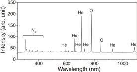
Fig. 4. Optical emission spectra observed around the outlet of the atmospheric-pressure plasma source.
Download figure:
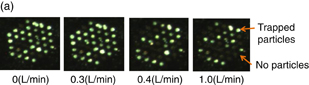
Standard image High-resolution imageSample trapping was carried out without operating the atmospheric pressure plasma source. Polyethylene particles (Mitsui Chemicals MIPELON XM-220) that had an average size of 30 µm were used, which was comparable to the size of a cell. When the vacuum pump operated, the particles were trapped at the holes. Some particles were also electrostatically agglomerated on the nozzle surface, which were removed using a deionizer. The remaining particles were trapped by pumping. The above process was repeated until multiple particles were trapped. The trapping force was dependent on the pressure inside the gas channel. The pressure was determined by the levels of injecting and evacuating gas flows. After a particle was trapped, the He gas flow rate was gradually increased until the particle detached (Fig. 5). Up until a gas flow rate of 0.3 L/min, the number of trapped particles was maintained at approximately 30. Beyond gas flow rates of 0.4 L/min, the number of trapped particles dropped to approximately 20. The persistence of attachments may be due to plastic deformations.
Download figure:
Standard image High-resolution image
Fig. 5. (a) Optical microscopy images of particle trapping under He gas flows of 0, 0.3, 0.4, and 1.0 L/min. A pump is used for gas evacuation. Bright white spots correspond to the trapped particles. (b) Number of trapped particles as a function of gas flow rate. In the case that a few particles were initially trapped in the nozzle holes, a higher gas flow rate was needed for release.
Download figure:
Standard image High-resolution image4.2. Localized plasma irradiation
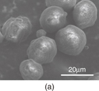
Localized plasma irradiation was carried out for the trapped polyethylene particles. The atmospheric-pressure plasma source was operated with a He gas flow of 0.2 L/min and a 30 W, 100 MHz VHF power supply. The plasma irradiation time was 1 min. Before plasma irradiation, the particle surfaces showed ridges [Fig. 6(a)], whereas afterwards the particles had smooth surfaces [Fig. 6(b)]. We consider three effects of the plasma reactions: thermal, chemical, and high-energy photons. The plasma gas temperature was obtained by analyzing the rotational spectra of (0–2) bands of the N2 second positive system (C 3Πu–B 3Πg).28) The rotational temperature ranged from 350 to 450 K (77 to 177 °C).29) Although the irradiation time was only 1 min, the plasma-irradiation-induced temperature was less than or equal to the melting point of the polyethylene particles (136 °C). If thermal effects were to become significant, the same MEMS technology could be used to implement a cooling function into the nozzle device. From the optical emission spectra, lines of O were observed. The oxygen radicals play important roles in the chemical reactions with carbon components in the polyethylene particles. In He gas plasma chemistry, when the metastable He atoms (2 3S and 2 1S) collide with the surface, the inner energies are released (up to approximately 20 eV), affecting the surface reactions. Because the atmospheric-pressure plasma generates high-energy vacuum ultraviolet (VUV) photons in the emissions,19,30) VUV-photon-induced photolysis may be important in polyethylene.31)
Download figure:
Standard image High-resolution image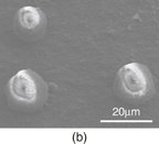
Fig. 6. SEM images of polyethylene particles (a) before and (b) after localized plasma irradiation.
Download figure:
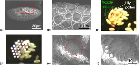
Standard image High-resolution imageThe localized plasma irradiation was applied to samples of lily pollen. Pollen is active under the same ambient conditions as the plasma irradiation. The pollen particles had an elliptical shape (major axis: 100–140 µm, minor axis 10–30 µm) [Fig. 7(a)]. The surface of the cell wall has networklike ridged structures [Fig. 7(b)]. The height of the ridges was about 1.5 µm. The pollen particles were attached to the MEMS nozzle [Fig. 7(c)] and exposed to the plasma irradiation for 10 min under a VHF power of 30 W [Fig. 7(d)]. No burning of the pollen was observed during the treatment. The cell wall of the affected area was thinned by the plasma irradiation [Figs. 7(e) and 7(f)]. The ridges were removed and a smooth surface was obtained. By carefully adjusting the irradiation conditions (e.g., gas flow rate, discharge power, and irradiation time), it would be possible to create a hole in the cell wall, which could potentially be used for drug administration. Unlike electroporation, the method described here can utilize not only the physical reactivity but also the chemical reactivity of the plasma itself.
Fig. 7. (a) SEM image of the pollen before plasma irradiation. Networklike structures are found on the surface. (b) Magnified SEM image of the area enclosed by the dotted line in (a). The networklike structure consists of ridges. The height of the ridge is about 1.5 µm. (c) Optical image of the trapped lily pollen before plasma irradiation. The dotted line indicates the area of nozzle holes. (d) Optical microscopy image of the pollen under plasma irradiation. Optical emissions are observed via the nozzle holes. (e) SEM image of the plasma-irradiated pollen. The plasma-irradiated area is indicated by the dotted circle. (e) Magnified image of the plasma-irradiated area. The plasma irradiation removed the ridges and a smooth surface was obtained.
Download figure:
Standard image High-resolution image
5. Conclusions
A novel MEMS nozzle device that can trap and release a sample was fabricated. The embedded masking technique was used to fabricate a multiple-height nozzle structure, improving the transfer efficiency of plasma-activated species. Samples were trapped at and released from the nozzle device by controlling the injection and evacuation gas flows. This MEMS device was used to successfully perform localized plasma irradiation on the surface of a plant cell, lily pollen. Localized plasma irradiation can contribute to elucidating the fundamental cell reactions. This work contributes to the development of new fields in plasma medicine.
Acknowledgements
The authors thank Professor Akihisa Yanase, Toyota Technological Institute, for providing polyethylene particles. This study was supported from 2011 by the Program for Forming Strategic Research Infrastructure, Ministry of Education, Culture, Sports, Science and Technology of Japan (S1101028), and by a Grant-in-Aid for Scientific Research on Innovative Areas (24110720).