

Abstract
We propose an ultrathin membrane-type active acoustic metasurfaces with deep-subwavelength thickness for arbitrarily steering the transmitted acoustic wavefront in real-time via adjustment of the static voltage distribution. The underlying mechanism is that the change of tension on the middle membrane by the stresses introduced by the voltage exerted on the piezoelectric layers modulates the surface phase profile. The performance of the resulting device is numerically demonstrated via versatile wave-steering phenomena. Our design with functionality and flexibility opens up possibility for the design of active acoustic functional devices and may find important application in diverse fields such as acoustic communication.
Export citation and abstract BibTeX RIS
The past few decades have witnessed considerable efforts devoted to the researches on acoustic metamaterials artificially structured to yield novel acoustical properties unattainable in the nature.1–4) Unlike the conventional optical and acoustic components relying on the modulation of the shape of medium for changing the propagation phase gradually, the recent advent of metasurfaces, as a special kind of metamaterial with a reduced dimension, helps to revisit the classical Snell's law and makes it possible to freely manipulate the reflected and refracted waves by introducing abrupt discontinuity of propagation phases as governed by the generalized Snell's law.5–12) Due to the innate lack of acoustic counterpart of surface plasmon polariton necessary for designing optical metasurfaces, acoustic metasurfaces therefore need to be implemented on the basis of inherently different mechanisms.13) Reference 14 propose the first design of acoustic metasurfaces with versatile wavefront manipulation capability by coiling up spaces and then experimentally demonstrate a proof-of-concept device.15,16) Acoustic metasurfaces have also been extensively exploited for realizing various fascinating wave-steering phenomena with applications such as in production of acoustic vortex,17–20) acoustic focusing,21–24) anomalous refraction/reflection,25,26) diffuse reflection27) and high-quality hologram.28) In comparison with the passive metasurfaces that can only have a fixed functionality once fabricated, the emergence of active acoustic metamaterials further improves the application potential in practice, which can be designed to yield adjustable properties based on various mechanisms such as by using reconfigurable electronic circuits29) and membranes controlled by magnetics,30) and recently arouses considerable research interests.31–34) However, the mechanism for designing active acoustic metasurfaces exempted from complicated digital electronic circuits or external magnetic fields, calling for further simplication and downscaling of the resulting devices which would be highly desired in practical applications ranging from ultrasound imaging and therapy to on-chip high-performance acoustic devices.
In this work, we propose the design of an active acoustic metasurface with tunable acoustical properties that can be freely controlled by simply changing the static voltage load, in need of no complicated phased-array circuit or external magnetic field. The proposed metasurface unit cell has a hybrid membrane structure made of low-density membranes attached with central decorated masses and piezoelectric (PZT) annuluses. Our mechanism is that, when a static voltage load is applied, the piezoelectric effect will lead to the deformation of the piezoelectric materials and break the stress balance on the annuluses due to the asymmetric bending deformation on the two opposite sides, making the phase shift of the transmitted wave dependent of the value of electric potential. This enables the resulting device composed of an array of such unit cells to engineer the transmitted wavefront at low frequency by adjusting the static voltage exerted on each annulus. We demonstrate the effectiveness of our mechanism numerically via several distinctive wave-steering functionalities which are substantial significance for broadening the practical applications of active acoustic metasurface-based devices.
The schematic of our proposed active metasurface is illustrated in Fig. 1(a), which consists of two identical hybrid membrane structures formed by depositing two piezoelectric circular rings on both sides of each membrane with a small steel plate attached to the center and a ultrathin air layer sealed in between. The black arrows represent the incident waves and the yellow arrow stands for refracted waves, respectively. For each piezoelectric layer, an electric circuit is attached to exert static voltage load between the two surfaces in a controlled manner as shown in the zoom-in view in Fig. 1(b). Due to the piezoelectric effect, the static voltage produces deformation of the piezoelectric materials which breaks the stress balance of piezoelectric annulus. Thereby the equal but opposite voltages on the two layers of the piezoelectric annulus will generate bending deformation due to the extending of one side and the contraction of the other side. The two piezoelectric annuluses are polarized in the thickness direction and made of PZT-5H material. This enables simple manipulation of the propagation phase of the acoustic wave after passing through the proposed unit cell by adjusting the electric potential of circuit. For the resulting active acoustic metasurface comprising an array of such unit cells, the phase profile of the refracted waves becomes a function of the spatial distribution of electric potential, and one can readily engineer the wavefront by modulating the static voltage load on each piezoelectric annulus differently. Here the mass density of the PZT-5H material is 7750 kg m−3. The density, Young's modulus and Poisson's ratio are 1420 kg m−3, 2.5 GPa and 0.34 for the membrane, and 7850 kg m−3, 205 GPa and 0.28 for decorated mass, respectively. The damping of membrane and the mechanical loss of the PZT-5H annulus are both 0.001. The radius R1 and thickness d1 of decorated mass are chosen as 4 and 1 mm. The middle layer, with a radius R2 of 25 mm and a thickness d2 of 0.25 mm, is the membrane made of low-density polyethylene. The two PZT-5H layers have a shape of an annulus whose width R3 is 8 mm with inner radius of 16.75 mm and the outer radius of 24.75 mm. The distance between two identical hybrid membrane structures, H, is 32 mm. Throughout the paper, the numerical simulations are performed by the finite element method based on commercial software COMSOL Multiphysics. Figure 1(c) shows the simulated frequency dependence of transmission coefficient for each unit cell of the proposed active metasurface, in which two resonance peaks can be observed in spectrum. It is worth stressing that we deliberately design the individual unit cell with two resonance peaks to achieve both smooth phase change and high transmission efficiency. By reducing the radius of the decorated mass, the further lower eigen-frequency of our proposed metasurface unit cell can be obtained. When the material parameters of the decorated mass are changed, the distance between the two resonance peaks will also change accordingly. The corresponding cross-section view of the total displacement fields of this hybrid membrane structures are shown in Figs. 1(d) and 1(e) at the first and second resonance frequencies. The first and second eigenmodes of the hybrid membrane structures are characterized by the in-phase oscillation (dipolar resonance) and out-of-phase oscillations (monopolar resonance) of the two membranes at f1 = 565 Hz and f2 = 605 Hz, respectively.35,36) By properly choosing the value of H, which notably affects the distance between two resonance peaks, we achieve both a high transmission efficiency and a relatively smooth phase change while keeping the ultrathin device thickness. Hence the resulting active metasurface device is expected to work near the first and second resonance frequencies with high transmission efficiency. In the current study, we choose the second resonance frequency (corresponding to a wavelength 20 times larger than the device thickness) to exemplify the functionality of our active acoustic metasurface to steer the refracted acoustic wavefront by modulating the static voltage distribution.
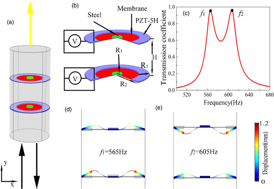
Fig. 1. (Color online) (a) The schematic diagram of an individual unit cell of the proposed active acoustic metasurface. (b) The zoom-in view of the configuration of the metasurface unit cell. (c) The simulated transmission coefficient as a function of frequency for this unit cell with two resonance peaks at f1 and f2, respectively. (d), (e) Cross-section view of the total displacement fields for the (d) first and (e) second eigenmodes at the two resonance frequencies.
Download figure:
Standard image High-resolution imageFor clarifying the fundamental mechanism of phase modulation underlying our design, the transmission coefficient (blue line) and phase shift (red line) of the refracted waves are plotted as functions of static voltage in Fig. 2(a) at the resonance frequency of 605 Hz. Here we use the bi-layer membrane structure for covering the full 2π span of phase control. For the sake of simplicity, we choose to use only eight discrete values of electric potential, instead of modulating it continuously, to cover the full 2π span with a discrete phase step of π/4, as marked by the eight black dots in Fig. 2(a). Figure 2(b) illustrates the spatial distribution of acoustic pressure of refracted waves for these eight units with eight discrete static voltages which clearly shows the propagation of incident wave has been delayed as expected after transmitting through the metasurface unit cell. Here the phase shift labeled as 5π/8 is one of the eight discrete values. We choose the relatively good point where the voltage is zero to realize the phase shift, because there is not an exact voltage value corresponding to the phase shift labeled as 5π/8 in Fig. 2(a). The zero voltage point corresponding to the transmission coefficient is 0.22. The height of the eight static voltage values correspond to the discrete phase shifts in Fig. 2(c). The varied colors represent the different static voltages, which results in different acoustic wavefront manipulations. When we change the static voltage distribution specifically, the spatially varying acoustic property is achieved at the frequency of monopolar resonance. In what follows, we will demonstrate the functionality and flexibility of our designed active acoustic metasurface via the production of three distinctive wave-steering phenomena by modulating the voltage distribution with no need of changing the geometry of metasurface device.

Fig. 2. (Color online) (a) The transmission coefficient and phase shift of the refracted waves as functions of the static voltage. Black dots: eight units to realize the desired discrete phase shifts. (b) The acoustic pressure strips of the refracted waves by eight unit cells of the active acoustic metasurface. (c) The corresponding distribution of static voltage needed for generating the spatial distribution of acoustic pressure of the refracted waves in Fig. 2(b) at the frequency of 605 Hz.
Download figure:
Standard image High-resolution imageFirst we will exemplify the performance of the proposed metasurface to redirect wave along the prescribed direction. In light of the generalized Snell's law,5) the refracted angle can be adjusted by designing the suitable phase profile along the x direction. In our design, the target angle of refraction is chosen as 45° at the frequency of 605 Hz. Figure 3(a) demonstrates the theoretical continuous phase profile (red line) and the discrete phase profile (black lines) provided by the active acoustic metasurface. The corresponding distribution of static voltage needed for producing such a phase profile is depicted in Fig. 3(b). The different colors represent varied input voltages, which results in different phase delay as expected after transmitting through the active acoustic metasurface. The numerical result of pressure field distribution is illustrated in Fig. 3(c) at the frequency of monopolar resonance, which proves that by modulating the static voltage exerted on each unit cell of the designed metasurface accordingly to the distribution shown in Fig. 3(b). The ripples on the incident wave side in Fig. 3(c) are due to the imperfect transmission for some of the unit cells. Even if the transmission coefficient at individual phase point is low, the effect on redirect wave appears small after passing through our active metasurface. The normal incidence beam can be redirected to the prescribed direction (marked by the black arrow).
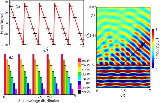
Fig. 3. (Color online) (a) The theoretical continuous phase distribution (red line) and the discrete phase distribution (black lines). (b) The bar graphs of corresponding static voltage distribution for anomalous refraction is plotted needed for producing the desired phase profile shown in (b). (c) The simulated pressure field distribution of the anomalous refraction beam at the frequency of 605 Hz. The black arrow refers to the prescribed direction of outgoing beam.
Download figure:
Standard image High-resolution imageNext we will demonstrate the potential of our designed active metamaterial to mimic an ultrathin planar lens for realizing effective convergence of the refracted wave, which has important application in medical ultrasound imaging and acoustic non-destructive testing. To design a flat acoustic lens, the hyperboloidal phase profile is employed on the metasurfaces and the phase  imposed at every point must satisfy the following equation

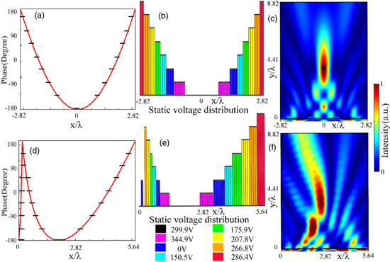
where f is the focal length. For a given focal length f = 4λ, the theoretical hyperboloidal phase distribution (red line) and the discrete phase distribution (black lines) supported by the active acoustic metasurface are shown in Fig. 4(a). The corresponding static voltage distribution for producing focused beam is depicted in Fig. 4(b). The refracted normalized intensity field distribution of numerical result is plotted in Fig. 4(c) at the frequency of 605 Hz, and the focus is marked by the black dot, which provides clear confirmation that remarkable focusing effect can be realized by the active acoustic metasurfaces. By changing the spatial distribution of voltage in Fig. 4(b), it is convenient to convert the above ultrathin converging lens to another device for generating self-bending beam propagating along convex trajectory without reconfiguring the device shape, which would be highly desired in many practical scenarios due to its unique ability of circumventing obstacles and self-constructing. To design a self-bending acoustic beam, the convex trajectory phase profile should be employed so that the phase shift  at every point along the x direction satisfy the following equation

where the r is the trajectory's radius. For a given radius r = 2λ, the theoretical phase profile (red line) and the discrete phase profile (black lines) provided by the active acoustic metasurface is shown in Fig. 4(d). The corresponding distribution of static voltage for generating self-bending beam propagating along convex trajectory is illustrated in Fig. 4(e). It is observed that self-bending wave propagates along the theoretical direction with a relatively long distance in Fig. 4(f) at the frequency of monopolar resonance. The imperfect self-bending beam is obtained due to the pressure from the 5π/8 unit cell with a relatively low amplitude. Although the transmission coefficients of the eight discrete cells are different, yet the focused beam and self-bending beam can be clearly observed after imposing the discrete phase profile. The numerical results of normalized intensity field distributions are in agreement with the theoretical prediction, which indicate that the effect of remarkable focused beam and self-bending beam can be realized by changing the static voltage distribution of active acoustic metasurfaces.
Fig. 4. (Color online) (a), (d) The continuous (red line) and discrete (black lines) phase profiles for producing (a) the focused beam and (d) self-bending beam propagating along the prescribed direction. (b), (e) The corresponding distributions of static voltage needed for producing (b) focused beam and (e) self-bending beam respectively. (c), (f) The numerical results of normalized intensity field distributions of (c) the focused beam and (f) the self-bending beam at the frequency of 605 Hz.
Download figure:
Standard image High-resolution image
In summary, we propose the design of ultrathin membrane-type active acoustic metasurface capable of achieving the versatile wavefront manipulation while with effectively simplified and downscaled configuration in comparison with the reported designs. Our active metasurface consists of two identical hybrid membrane structures formed by depositing two piezoelectric circular rings on both sides of each membrane with a small steel plate attached to the center. The applied static voltage induces stresses to generate bending deformation in the piezoelectric layers, which changes the tension applied on the hybrid membrane structure. Therefore, by modulating the static voltage exerted on each metamaterial unit cell, the whole active metasurface device can be tuned to produce different phase profiles needed for realizing unconventional wave-steering phenomena such as the anomalous refraction, focused beam, and self-bending beam. The numerical results verify the theoretical predictions and the resulting device is demonstrated via the production of the versatile wave-steering phenomena without changing the device geometry. Besides, it is demonstrated the proposed active metasurface supports versatile wavefront manipulation with deep-subwavelength thickness. Despite the low transmission efficiency of this specific unit cell with phase shift of 5π/8, the wave-steering phenomena demonstrated in the current study have not been appreciably affected such as the focused beam, anomalous refraction and self-bending beam. For achieving more precise spatial distribution of acoustic energy, we can use more sophisticated designs composed of three or more resonance peaks to ensure high transmission for each unit cell. The experiment can be easily implemented as long as we ensure the high precision of the sample and the consistency of the piezoelectric annuluses in the experiment process. Moreover, it is important to mimic the plane wave incident condition in a large scale in practice. The experimental realization of the active acoustic metasurface would be the goal of our future work. Our design with functionality and adjustability constitutes another step towards integration of the functionalities of acoustic metasurfaces and opens up possibilities for the design and application of multi-functional acoustic devices, which would may have significant and far-reaching impact on many diverse fields such as acoustic communication and new generation of programmable metasurfaces.
Acknowledgments
This work was supported by National Key R&D Program of China (Grant No. 2017YFA0303700), the National Natural Science Foundation of China (Grant Nos. 11634006, 11374157 and 81127901), and A Project Funded by the Priority Academic Program Development of Jiangsu Higher Education Institutions.