the Creative Commons Attribution 4.0 License.
the Creative Commons Attribution 4.0 License.
 | 11 Mar 2021
Wake redirection at higher axial induction
The energy produced by wind plants can be increased by mitigating the negative effects of turbine–wake interactions. In this context, axial-induction control and wake redirection control, obtained by intentionally yawing or tilting the rotor axis away from the mean wind direction, have been the subject of extensive research but only very few investigations have considered their combined effect. In this study we compute power gains that are obtained by operating tilted and yawed rotors at higher axial induction by means of large-eddy simulations using the realistic native National Renewable Energy Laboratory (NREL) 5 MW actuator disk model implemented in the Simulator for On/Offshore Wind Farm Applications (SOWFA). We show that, for the considered two-row wind-aligned array of wind turbines, the power gains of approximately 5 % obtained by standard wake redirection at optimal tilt or yaw angles and reference axial induction can be more than tripled, to above 15 %, by operating the tilted or yawed turbines at higher axial induction. It is also shown that significant enhancements in the power gains are obtained even for moderate overinduction. These findings confirm the potential of overinductive wake redirection highlighted by previous investigations based on more simplified turbine models that neglected wake rotation effects. The results also complement previous research on dynamic overinductive yaw control by showing that it leads to large power gain enhancements also in the case where both the yaw and the overinduction controls are static, hopefully easing the rapid testing and implementation of this combined-control approach.
- Article
(2617 KB) - Full-text XML
- BibTeX
- EndNote


In wind farms, wind turbines shadowed by the wakes of other upwind turbines experience a decrease in the mean available wind speed and an increase in turbulent fluctuations, resulting in decreased extracted wind power and increased fatigue loads (see Stevens and Meneveau, 2017, and Porté-Agel et al., 2019, for a review). In currently installed wind farms, however, each turbine is typically operated in “greedy” mode, maximizing its own individual power production. As the greedy operation mode does not generally lead to the global optimum, where the energy production of the whole wind farm is maximized (see, e.g., Steinbuch et al., 1988), a number of different approaches have been proposed where the collective control of all turbines is used to increase the power production of the whole wind farm by mitigating the negative effects of turbine–wake interactions (see Knudsen et al., 2015, and Boersma et al., 2017, for a review). Among the many proposed approaches, two have received particular attention: axial-induction control and wake redirection control, which can be static (the control is steady if the incoming wind conditions are) or dynamic (the control can be unsteady even for steady incoming wind conditions).
In axial-induction control the induction factors of selected (usually upwind) turbines are steered away from the greedy operation mode in order to increase the power production of other (usually downwind) turbines. While static axial-induction control has not demonstrated significant power gains in realistic settings (Knudsen et al., 2015; Annoni et al., 2016), dynamic axial-induction control has shown promise for significant power gains (Goit and Meyers, 2015; Munters and Meyers, 2017). In wake redirection control the intentional misalignment of rotor axes from the wind direction is used to deflect turbine wakes in the horizontal or in the vertical direction by acting on yaw or tilt angles, respectively, with a documented increase in the global power produced by the wind farm (Dahlberg and Medici, 2003; Medici and Alfredsson, 2006; Jiménez et al., 2010; Fleming et al., 2014, 2015; Campagnolo et al., 2016; Howland et al., 2016; Bastankhah and Porté-Agel, 2016).
In two recent studies (Cossu, 2020a, b) we have shown that an appropriate combination of (static) tilt and (static) axial-induction control results in a significant enhancement in the global power gains obtained in spanwise-periodic wind turbine arrays. In these studies, for the considered three-row turbine arrays, power gains were observed to be highly enhanced (up to a factor of 2 or 3) when the turbines with the rotor tilted by the optimal angle () were operated with a disk-based thrust coefficient higher than in the baseline case ().
The results reported in these previous studies (Cossu, 2020a, b) were obtained with an actuator disk model, where wake rotation and the radial distribution of actuator disk forces were neglected, and the turbines were assumed to operate at constant given . This highly idealized setting, used in many previous investigations (e.g., Calaf et al., 2010; Goit and Meyers, 2015; Munters and Meyers, 2017), has been instrumental in obtaining general results not depending on the specific turbine-control law and blade design, but it calls for confirmation by means of more realistic turbine models. Hence, a first goal of this study is to determine the power gains that can be obtained with high-induction (overinductive) tilt control when realistic turbine models are used that take into due account blade design, wake rotation and the controller specificity. This goal is addressed in the first part of this study by making use of the native actuator disk model of the Simulator for On/Offshore Wind Farm Applications (SOWFA; Churchfield et al., 2012) for the National Renewable Energy Laboratory (NREL) 5 MW turbine. In this implementation of the turbine model the radial dependence of the actuator disk force as well as wake rotation and is computed from turbine blade properties by means of a blade-element approach, and the NREL 5 MW's five-region realistic controller (Jonkman et al., 2009) is used.
In the second part of the study we address the case of yaw control. Indeed, the increased power gains obtained by operating tilted turbines at higher thrust coefficients mostly result from the increase in wake deviations obtained without a penalization of the power production of the tilted turbine. Overinductive wake deflection could therefore be beneficial also in the case of yaw control, where it is known that higher thrust coefficients also result in larger wake deviations (Jiménez et al., 2010; Howland et al., 2016; Shapiro et al., 2018). Surprisingly, however, only very few studies have investigated the potential benefits of combining axial-induction control and yaw control. Park and Law (2015), based on simplified wake models and advanced optimization techniques, show that significant power gains can be obtained by combining static yaw and induction control, but they do not analyze the respective effects of yaw and induction; furthermore, their optimal solutions in the aligned case converge to an underinductive operation mode for yawed turbines. Munters and Meyers (2018a, b) show, by means of adjoint methods with full-state information and an actuator disk turbine model where wake rotation is neglected, that high power gains result from the combination of dynamic yaw and axial-induction controls, with Munters and Meyers (2018b) highlighting the potential of quasi-static yaw control in the (dynamic) overinductive regime. Thus, from these previous studies, it is not clear if significant power gains could be realized in the overinductive regime when both the yaw and the axial-induction control are static, nor is it clear to what extent the neglected wake rotation effects are important.
The second objective of the present study is therefore to ascertain if significant power gains can be obtained with a combination of static yaw control and static axial-induction control by operating yawed turbines at higher axial induction and including the effect of wake rotation in the turbine model. An affirmative answer would allow the isolation of the mean wake redirection as the most relevant physical effect at play (instead of, e.g., the dynamical adaptation to the incoming wind) and indicate that it is robust with respect to the inclusion of wake rotation effects. Furthermore, if successful, static overinductive yaw control could be easily implemented by simply updating existing yaw-control protocols with a prescription of the suitable turbine rotor-collective blade-pitch angle (controlling the axial induction and the thrust coefficient) for each accessible yaw angle.
The potential of static overinductive wake redirection is investigated by computing power gains that can be obtained in a wind turbine array composed of two spanwise-periodic rows of wind-aligned turbines where the same control is applied to all upwind-row turbines, while downwind-row turbines are left in default operation mode. This idealized configuration, which is an extension to the spanwise-periodic case of the two-turbine configuration considered by Fleming et al. (2015), is chosen in order to keep the physical interpretation of the results simple by isolating the effects of tilt or yaw angle and axial induction of the upwind turbines without entering the problem of the optimization of these parameters encountered in more realistic configurations with more rows. As such, this approach is a necessary first step needed to isolate the main trends at play before considering more realistic settings. Importantly, the relevance of these power gains will be tested without excessive assumptions by means of large-eddy simulations in the atmospheric boundary layer using a turbine model which includes the effects of wake rotation, radial-force distribution and a realistic turbine controller.
We anticipate that substantial enhancements (up to a factor of 3) in the power gains induced by wake redirection are found when operating the tilted or yawed turbines at higher axial induction.
The formulation of the problem at hand is introduced in Sect. 2. Results are reported in Sect. 3 and further discussed in Sect. 4. Additional details on used methods are provided in Appendix A, and additional results about the effect of using a less realistic turbine model, where wake rotation effects are neglected, are reported in Appendix B.
We address the case of two spanwise-periodic rows of wind turbines immersed in a neutral atmospheric boundary layer (ABL) at latitude 41∘ N. The flow is simulated by means of large-eddy simulations with SOWFA (the Simulator for On/Offshore Wind Farm Applications developed at the NREL; see Churchfield et al., 2012), which solves the filtered Navier–Stokes equations including the Coriolis acceleration associated with Earth's rotation and the compressibility effects modeled by means of the Boussinesq approximation (see Appendix A for more details and Churchfield et al., 2012, for the explicit expression of the solved equations and a full description of the used formulation and modeling assumptions used in SOWFA).
NREL 5 MW turbines (Jonkman et al., 2009) are considered, which are modeled with SOWFA's native actuator disk method, where wake rotation, the radial distribution of aerodynamic forces and the thrust coefficient are all computed from blade properties, providing a reliable description of the wake structure except in the near-wake region. We also make use of SOWFA's native implementation of the NREL 5 MW's realistic five-region turbine controller based on generator torque control in the Region II regime corresponding to the mean wind speeds considered in the following; in this regime we modify axial induction by changing the rotor-collective blade-pitch angle β. Higher axial inductions are obtained by enforcing negative values of β (see Appendix A), resulting in higher local thrust coefficients , where T is the thrust magnitude, ρ is the fluid density, and un is the disk-averaged wind velocity component normal to the rotor disk of area . For all the considered cases the local power coefficient (where P is the power) is well approximated as , with χ=0.9; results of trends are therefore not shown in the following. The incoming flow, generated by means of a precursor simulation in a 3 km×3 km domain in the absence of turbines, has a 100 m thick capping-inversion layer centered at H=750 m, separating the neutral boundary layer with constant potential temperature (θ=300 K) from the geostrophic region above where the vertical potential-temperature gradient is positive . In the capping-inversion layer this gradient is . In the precursor simulation, the ABL is driven by a pressure gradient adjusted to maintain a horizontally averaged mean of 8 m s−1 from the west at z=100 m (a few meters above hub height zh=89 m). In the region spanned by the turbines (z<152 m) the streamwise mean velocity is well approximated by the logarithmic law, and the vertical wind veer is less than 4∘ (see Cossu, 2020b, where the same ABL has been already considered). The streamwise turbulence intensity of the incoming wind at hub height is 5.7 % for the enforced low roughness length (z0=0.001 m) typical of offshore conditions.
Simulations in the presence of wind turbines are repeated in the same 3 km×3 km domain starting from the solution of the precursor simulation at t0=20 000 s, corresponding to a well-developed ABL, up to t1=30 000 s. Statistics are computed starting from t=24 000 s, when turbine wakes are fully developed. The pressure gradient issued from the precursor simulation is enforced during the simulation with turbines, and the (previously stored) ABL solution at x=0 (west boundary) is used as an inflow boundary condition.
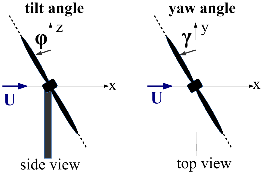
Figure 1Definition of the positive rotor tilt and yaw angles φ and γ used in the present study. Positive tilt angles can be obtained for downwind-oriented rotors to avoid blade–tower hits.
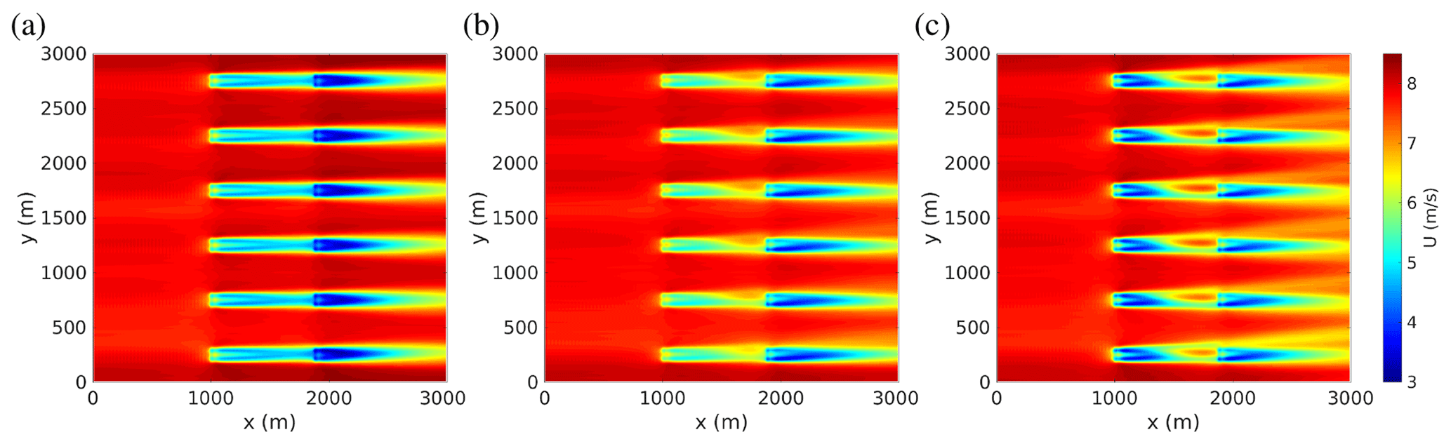
Figure 2Tilt control: mean (temporally averaged) streamwise velocity field in the horizontal plane at hub height obtained (a) in the baseline case, where all turbines are operated in default mode; (b) with upwind turbines tilted by and operated at the default rotor-collective blade-pitch angle ; and (c) with upwind turbines tilted by and operated at higher induction (). The mean wind is from the west (from the left, parallel to the x axis). Note that the entire 3 km×3 km computational domain is shown in the figure and that periodic boundary conditions are applied on the north and south boundaries.
In each (spanwise-periodic) row, turbines are spaced by 4D in the spanwise direction (where D=126 m is the rotor diameter), and the two rows are spaced by 7D in the streamwise direction, with corresponding turbines of each row aligned with respect to the mean wind direction (see Fig. 2, where the full computational domain is shown). Downwind-row turbines are always operated in default mode with the rotor axis at yaw angle (aligned with the mean wind at z=100 m), tilt angle to prevent the blades from hitting the tower (see Fig. 1 for a definition of φ and γ) and rotor-collective blade-pitch angle . In the baseline (reference) case upwind-row turbines are also operated in default mode. The baseline case is then compared to a set of controlled cases where all the turbines of the upwind row are operated at the same non-zero tilt or yaw angle and, possibly, non-zero rotor-collective blade-pitch angle.
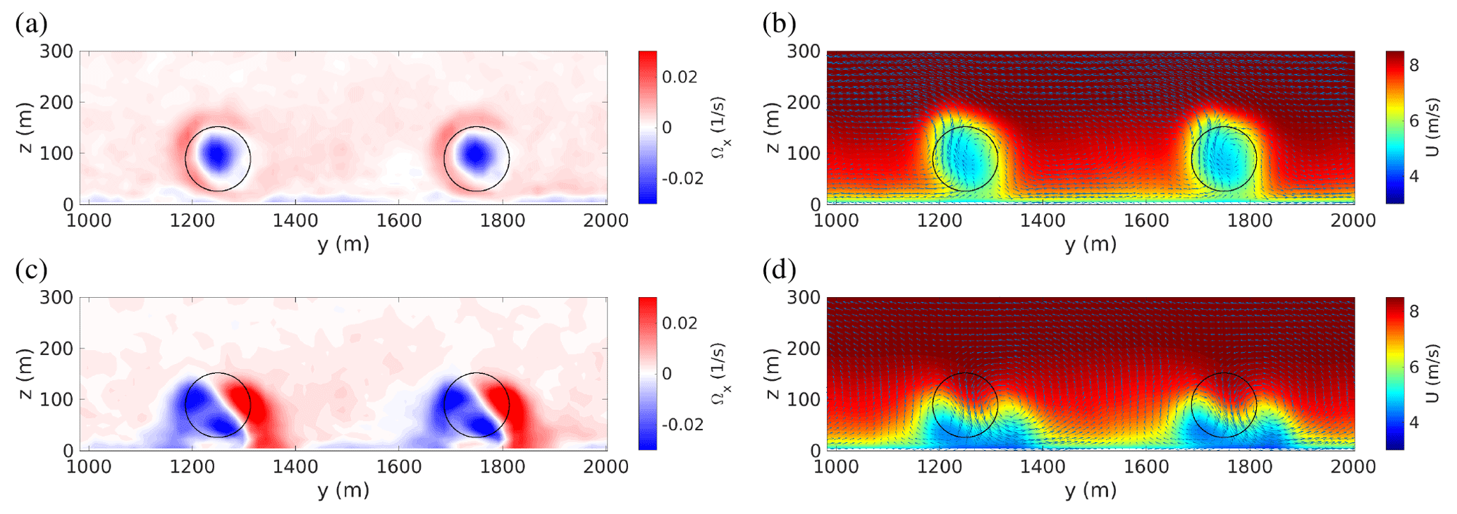
Figure 3Tilt control: cross-stream view of the mean streamwise vorticity and velocity fields in the baseline case (a, b) and with upwind turbines tilted by and operated at (c, d). From the streamwise vorticity fields (a, c), extracted 3D downstream of the first turbine row, the negative streamwise vorticity in the wake core associated with wake rotation can be clearly seen in the baseline case (a) as well as its combination with the two counter-rotating streamwise vortices forced by the tilted rotor (c). Streamwise (color scale) and cross-stream (arrows) velocity fields (b, d) are extracted upstream of the second row of turbines; to improve readability only the fields of the two central turbine columns (between y=1000 and 2000 m) are shown. The circles in black represent the perimeter of downstream rotors.
3.1 Effect of overinduction on tilt control
In the baseline case (all turbines operated with , , ), the usual situation is found where the turbines of the downwind row see a strongly reduced mean wind (see Figs. 2a and 3b), therefore producing only ≈30 % of the total power, i.e., ≈40 % of that produced by the upwind row of turbines (see Fig. 4b). The effect of wake rotation is clearly discernible in the mean streamwise vorticity field (see Fig. 3a). In the following, power gains will be computed with respect to the mean power PRef produced in this baseline case.
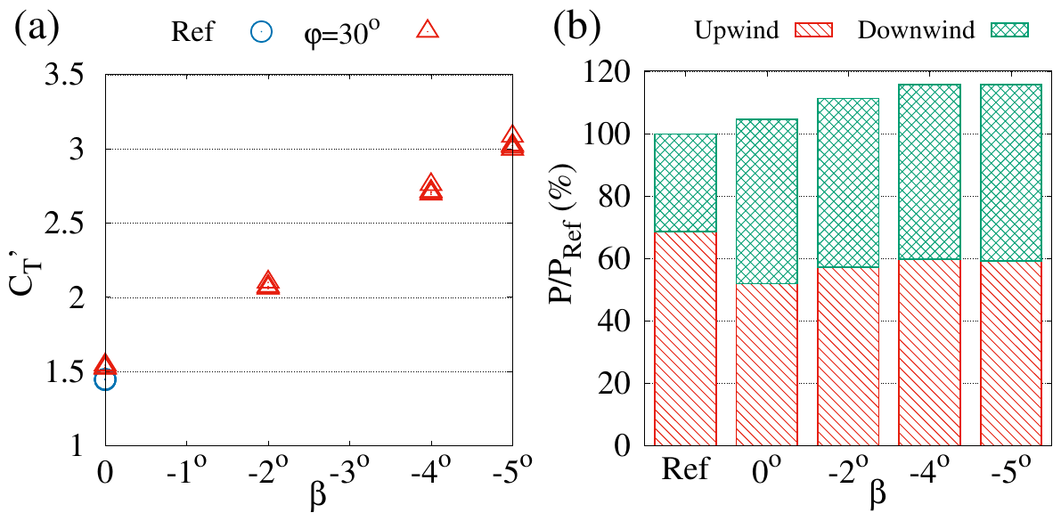
Figure 4Effect of enforcing negative rotor-collective blade-pitch angles β on upwind-row turbines tilted by . (a) Temporally averaged local thrust coefficient of the individual turbines of the upwind row. (b) Wind power extracted by the upwind (hatched red) and downwind (cross-hatched green) rows of turbines normalized by the total power PRef produced in the baseline case (Ref).
We then consider the case where upwind-row turbines are tilted by , an angle in the range where the best power gains have been found in previous studies (Fleming et al., 2014, 2015; Cossu, 2020a, b), while keeping their rotor-collective blade-pitch angle at the default value . In this case, the wakes of the upwind turbines are pushed down by the tilt-induced downwash, increasing the mean wind available to downwind turbines (see Fig. 2b). The tilt-induced decrease in power produced by upwind-row turbines is compensated by the increase in the power produced by downwind-row turbines, resulting in global power gains of ≈5 % for (see Fig. 4b).
In a further step, the rotor-collective blade-pitch angle of the tilted upwind-row turbines is changed. Enforcing increasingly negative values of β (i.e., increasing the mean angle of attack of all rotor blades, as explained in Appendix A) results in increased thrust coefficients (increased axial induction) which, starting from in the baseline case (), attain for in turbines tilted by (see Fig. 4a).
The effect of the increased thrust is twofold: (a) the downwash associated with the stronger tilt-induced streamwise vortices is reinforced (see Fig. 3c and d), which increases the mean wind speed seen by downstream rotors (see Figs. 2c and 3d) and their extracted power despite the higher wake deficit of upwind turbines (compare Fig. 2c to b), and (b) the power produced by tilted turbines is also (slightly) increased1 (see Fig. 4b). The combination of these two effects results in optimal power gains which are highly enhanced (almost tripled) with respect to those obtained by tilt without overinduction.

Figure 5Effect of the tilt angle φ on (a) the local thrust coefficients of upwind-row turbines when they are operated with (default axial induction) or with (strongly overinductive regime), (b) the total power gain for selected values of β.
Finally, a full set of φ–β combinations is considered. For these simulations we observe that, for turbines operated at constant β, the increase in with φ is noticeable only for φ ≳ 30∘, as shown in Fig. 5a (we have verified that this increment is consistent with the effects of changing the tilt angle and the associated change in the induction factor). Considering the power gains with respect to the baseline case, from Fig. 5b it can be seen that the maximum power gains are reached for , with optimal values obtained with significant overinduction (power gains larger than 15 % for ), which are almost 3 times those (≈5 %) obtained with tilt control at reference induction rates (). This effect of overinduction in tilt control is very strong: from Fig. 5b it is indeed also seen that at , even with the moderate rotor-collective blade-pitch angle , power gains have already almost doubled with respect to standard tilt control with .
The high enhancement in power gains obtained by combining overinduction with tilt control with respect to those obtained by standard tilt control at baseline induction is consistent with that found in our previous studies (Cossu, 2020a, b), therefore confirming the robustness of this trend. The absolute levels of power gains are, however, smaller than those reported by Cossu (2020a, b) both because two-row arrays are considered here instead of the previously considered three-row arrays (which have higher power gains; see, e.g., Annoni et al., 2017) and because wake rotation effects, neglected in the previous studies, are here taken into account (see Appendix B for further details).
3.2 Effect of overinduction on yaw control
We now evaluate the benefits of combining static yaw control with static overinduction. We proceed similarly to the tilt-control case by using the same precursor simulation and the same baseline case, where all turbines operate at default values , and .
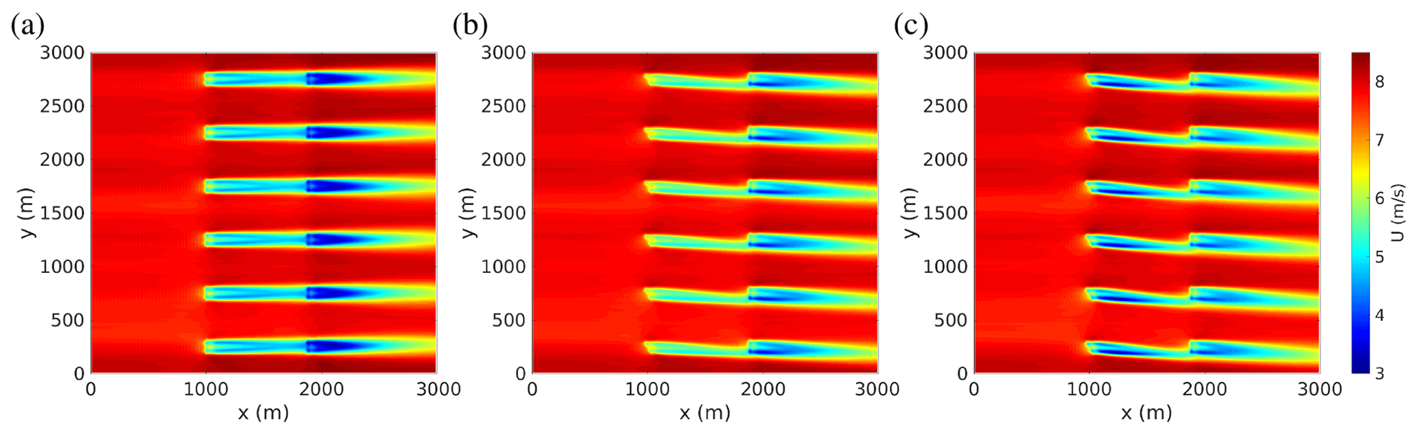
Figure 6Yaw control: mean streamwise velocity field in the horizontal plane at hub height obtained (a) in the baseline case, where all turbines are operated in default mode (, ; same as Fig. 2a, reproduced here to ease the comparison); (b) in the case with upwind turbines yawed by and operated at the default ; and (c) with upwind turbines yawed by and operated at higher induction ().
We first simulate the standard yaw control where the yaw angle γ of upwind-row turbines is changed (while keeping the other parameters, and , unchanged), resulting in the well-known horizontal deviation in upwind-row turbine wakes and the increase in the mean wind speed seen by downwind rotors (see Fig. 6b). From Fig. 8b it is seen that the increase in the power produced by downwind-row turbines compensates the reduction in the power produced by the yawed turbines (upwind-row), resulting in maximum power gains of ≈5 % obtained for , similar to the values found by Fleming et al. (2015) for the two-turbine case.
Increasing the local thrust coefficient by means of increasingly negative blade-pitch angles in yawed turbines (see Fig. 8a) has effects similar to those observed for the tilt-control case: an increase in velocity deficits in upwind-row turbine wakes but also their higher deviation away from downwind turbines (see Figs. 6c and 7b) induced by the stronger yaw-induced, vertically staked, counter-rotating streamwise vortices (see Fig. 7a), resulting in an increase in the mean power produced by all turbines with respect to the standard yaw-control case with (Fig. 8b).
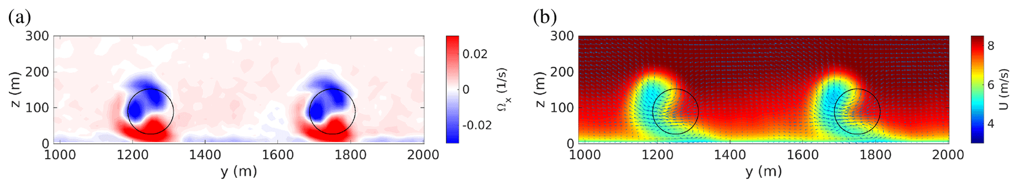
Figure 7Yaw control: cross-stream view of the mean streamwise vorticity and velocity fields with upwind turbines yawed by and operated at . The signature of the two vertically staked counter-rotating streamwise vortices forced by the yawed rotor combined with wake rotation is clearly visible in the streamwise vorticity field (a) extracted 3D downstream of the first turbine row. Their effect on the lateral displacement of the wake is clearly discernible in the streamwise (color scale) and cross-stream (arrows) velocity fields (b) extracted upstream of the second row of turbines. Only the fields of the two central turbine columns (between y=1000 and 2000 m) are shown.
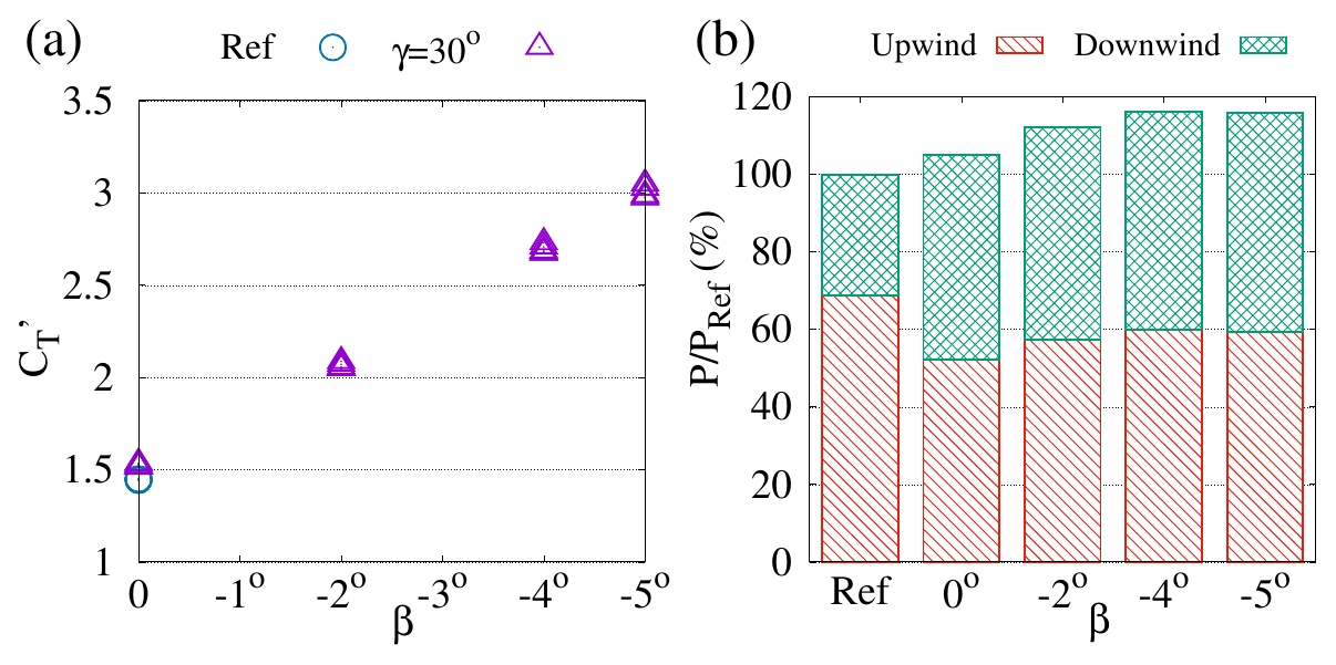
Figure 8Effect of changing the rotor-collective blade-pitch angle β of turbines yawed by . (a) Local thrust coefficient of the turbines of the upwind row. (b) Wind power extracted by the upwind (hatched red) and downwind (cross-hatched green) rows of turbines normalized by the total power PRef extracted in the baseline case.
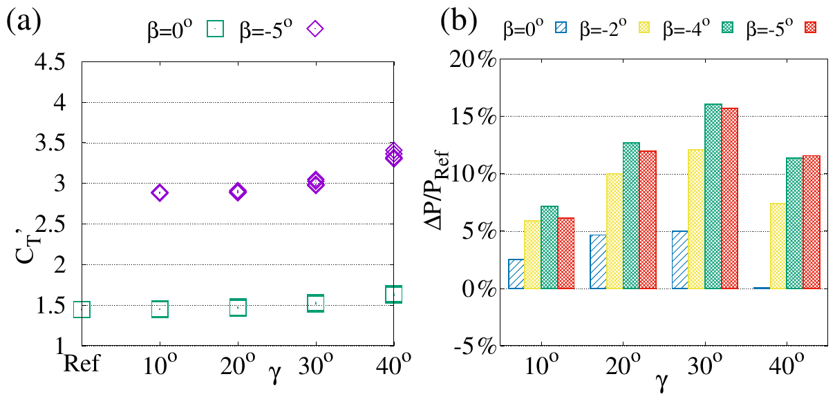
Figure 9Effect of the yaw angle γ on (a) the local thrust coefficients of upwind-row turbines when they are operated at or at and (b) power gains for selected values of rotor-collective blade-pitch angle β.
The analysis of a full range of γ–β combinations leads to results similar to those obtained for the tilt-control case. A non-negligible increase in is observed for large yaw angles γ ≳ 30∘ when operating at constant β, as reported in Fig. 9a, and global power gains obtained by yaw control are highly enhanced when yawed turbines are operated at higher induction (more negative values of the rotor-collective blade-pitch angle β). Also similarly to the tilt-control case, maximum power gains are obtained for regardless of the β value. Overall optimal power gains (above 15 %) are reached for relatively high overinduction (). Also in this case, power gains obtained by yaw control are more than doubled already for and almost tripled for the optimal value with respect to the standard operation mode () at the same yaw angle .
These results confirm the first intuition that, also in the static yaw-control case, static overinduction leads to a substantial improvement of the power gains which is based on the same mechanisms discussed for the tilt-control case confirming, that these mechanisms are quite robust.
The main goal of this study was to assess the magnitude of global power gains that can be obtained in wind turbine arrays by combining static wake redirection control and static axial-induction control operating tilted or yawed turbines at higher axial induction (overinduction). Results have been obtained by means of large-eddy simulations of a two-row array of NREL 5 MW turbines in a neutral atmospheric boundary layer.
In the first part of the study we consider the effect of higher induction on tilt control by using an actuator disk model less idealized than the one used in our previous studies of this approach. The results confirm that, also with this more realistic turbine model, power gains can be highly increased by operating tilted turbines at higher induction (power gains above 15 % are found for the considered set of parameters compared to ≈5 % obtained with default induction). This substantial enhancement in power gains due to the use of overinduction in tilt control is consistent with those found in our previous studies, but the absolute levels of the power gains are smaller because of the differences in array configurations and in the used turbine models. Indeed, when included in the turbine model, wake rotation results in an inclination of the formerly vertical downwash, which displaces higher-altitude, higher-speed fluid towards downstream rotors, and, as a consequence, and also results in a decrease in tilt-induced power gains.
In the second part of the study we ascertain if similar power gain enhancements can be obtained by combining static overinduction with static yaw control. To this end, we have first considered the standard case where yawed turbines are operated at the reference rotor-collective blade-pitch angle β=0, finding power gains of the order of 5 %, similar to those found in many previous studies (e.g., Fleming et al., 2015, for the two-turbine case). We then show that a very significant increase in power gains (almost threefold, up to ≈15 % for the cases considered) is obtained by operating yawed turbines at higher induction, similarly to what was found for tilt control.
The findings concerning the static overinductive yaw control are probably the most relevant of this study for short-term applications because they show that significant power gains can be realized with a simple static overinductive yaw control in a realistic model (the atmospheric boundary layer with NREL 5 MW turbines simulated with SOWFA) where wake rotation effects are fully taken into account. They also probably isolate the main physical mechanisms underlying the significant power gains found by Munters and Meyers (2018a, b) by means of combined (dynamic and static) yaw and (dynamic) induction control using adjoint methods with full-state information on large-eddy simulations where the turbines were modeled with a simplified actuator disk method neglecting wake rotation effects. Furthermore, static overinductive yaw control is suitable for immediate experimental testing with most existing standard horizontal-axis wind turbines unlike tilt control which is promising for specifically designed future generation, downwind-oriented and/or floating turbines (Bay et al., 2019; Nanos et al., 2020).
Another important result, obtained for both tilt and yaw overinductive controls, is that while maximum power gains (≈15 %) are obtained for relatively large rotor-collective blade-pitch angle () for the optimal large tilt and yaw angles (), significant power gains (≈10 %) are already obtained for smaller values , showing the robust beneficial effect of even moderately overinductive turbine operation.
It is also to be noted that here we have considered only two rows of turbines and a single configuration, with a small value of the ratio of rotor diameter to the ABL thickness, but that higher power gains can be expected for a larger number of turbine rows (Park and Law, 2015; Annoni et al., 2017; Cossu, 2020a) and for larger values of (Cossu, 2020a, b).
Additional investigations are, however, necessary to further refine, in many directions, the conclusions of the present study. A first important issue is to understand what the effects of overinduction are on the static and dynamic structural loads experienced by the blades of tilted and yawed turbines. A complete aeroelastic analysis based on higher-fidelity simulations making use of the actuator line method, requiring more refined grids and time steps and larger computational resources, is highly desirable, especially for the largest considered values of the yaw, tilt and pitch angles, where the near- and middle-wake structures are probably more sensitive to details of the turbine model.
Other issues are wind direction and array configuration. The present study is limited to a two-row array in the wind-aligned case, but it is, of course, important to evaluate power gains in arrays with many more rows also in non-aligned configurations. This kind of analysis, where the optimal combination of tilt, yaw and pitch angles of all turbines has to be computed for a high number of wind directions and intensities, would be too computationally demanding if performed by means of large-eddy simulations and is customarily based on less computationally demanding simplified sets of equations where the accurate modeling of the controlled wakes is of primary importance (see, e.g., Boersma et al., 2017). In this context, the results presented in the present study could be used to help in the improvement and validation of simplified wake models in regimes of moderate to high tilt or yaw, particularly in the case of significant overinduction. Such improved models would allow for more reliable predictions of annual energy production gains obtained with overinductive yaw or tilt control for realistic wind roses and wind farm configurations by using advanced optimization methods such as those used by Park and Law (2015).
Finally, it would be very interesting to ascertain if additional power gain enhancements could come from the simultaneous activation of tilt, yaw and axial-induction control. It might indeed be possible that, as a consequence of the symmetry breaking associated with wake rotation effects and Coriolis acceleration, optimal power gains are obtained with “hybrid” yaw–tilt rotor-axis rotations even in wind-aligned configurations. This is the subject of current intense research effort.
The large-eddy simulations presented in this study are performed with SOWFA, a set of libraries and codes able to simulate atmospheric flows over wind turbines (Churchfield et al., 2012) that is based on the OpenFOAM software environment designed to solve partial differential equations by means of finite-volume spatial discretization on unstructured meshes (Jasak, 2009; OpenCFD, 2011). The filtered Navier–Stokes equations are solved using the Smagorinsky (1963) model to approximate subgrid-scale stresses, with compressibility effects accounted for by means of the Boussinesq approximation and Earth's rotation effects accounted for by the Coriolis acceleration term in the equations (see Churchfield et al., 2012, for all details on the used formulation and for a validation of the code in the atmospheric boundary layer). Schumann (1975) stress boundary conditions, modeling the effect of ground roughness, are applied near the ground, and slip boundary conditions are enforced at the top of the solution domain. The solutions are advanced in time using the PIMPLE scheme, which is a combination of the PISO (Pressure-Implicit with Splitting of Operators) and SIMPLE (Semi-Implicit Method for Pressure-Linked Equations) schemes.
Periodic boundary conditions are applied in the x (west–east) direction for the preliminary “precursor” simulations, where the atmospheric boundary layer flow is computed in the absence of wind turbines in order to generate realistic inflow wind conditions (Keating et al., 2004; Tabor and Baba-Ahmadi, 2010; Churchfield et al., 2012). The mean pressure gradient is adapted in order to maintain (horizontally averaged) mean westerly winds of 8 m s−1 at z=100 m. The time history of the mean pressure gradient and of the solution at x=0 is stored and then used in the simulations with wind turbines, which are run in the same domain with the same grid but removing the periodicity constraint in the streamwise direction and replacing it with an inflow condition enforcing the solution found at x=0 in the precursor simulation. Periodic boundary conditions are applied in the y (south–north) direction for both precursor simulations and simulations with turbines.
The solution domain extends 1 km in the vertical direction and 3 km×3 km along the x and y axes and is discretized with cells extending 15 m×15 m in the x and y directions and 7 m (near the ground) to 21 m (near the top boundary) in the vertical direction; Δt=0.8 s time steps are used to advance the solution. These parameters keep the number of data stored in the precursor simulation manageable.
The aerodynamic forces developing on NREL 5 MW turbines, having a D=126 m rotor diameter and zh=89 m hub height (Jonkman et al., 2009), are modeled with SOWFA's native actuator disk method based on the blade-element method (BEM). The forces exerted on the fluid are computed for each radial blade section by using the lift and drag coefficients cL(α) and cD(α) associated with the local NREL 5 MW blade profiles and the local angle of attack , computed as the difference between the angle ϕ formed by the relative wind seen by the blades with the rotor plane and the local pitch angle, which is the sum of the local twist angle θ of the blades and the rotor-collective blade-pitch angle β (the reader is referred to, e.g., Burton et al., 2001, and Sørensen, 2011, for a detailed discussion of turbine modeling in general and of the BEM in particular). The Gaussian projection of the discretized body forces proposed by Sørensen and Shen (2002) is also used with a smoothing parameter ε=20 m to avoid numerical instabilities (Martínez-Tossas and Leonardi, 2013).
The NREL 5 MW five-region controller implemented in SOWFA is used to control the turbine's rotational speed and axial induction. In the Region II regime, the one accessed in the presented simulation, the turbine is driven to the design point (tip-speed ratio and thrust coefficient corresponding to the maximum power coefficient for an isolated non-tilted, non-yawed turbine) by means of generator torque control at the default rotor-collective blade-pitch angle . In this regime, we enforce the axial-induction control by changing the rotor-collective blade-pitch angle β while leaving the other parameters of the generator torque controller unchanged.
The local thrust coefficient is retrieved from the computed turbine thrust magnitude and rotor-averaged normal mean wind speed un by making use of its definition .
A quantitative analysis of the effect of the improved actuator disk method (ADM) model used in the present study by means of a direct comparison with the results obtained in Cossu (2020b) is not possible due to the difference in the considered array configurations (two arrays here, three in Cossu, 2020b). Additional simulations of tilt control have therefore been performed by using the same turbine model (which we denote as ADMC) used in Cossu (2020b) for the same array configuration used in the present study. We recall that, contrary to SOWFA's ADM used in the present study, in the ADMC model wake rotation effects are neglected, and a uniform load is assumed over the rotor disk that is assumed to operate at constant .
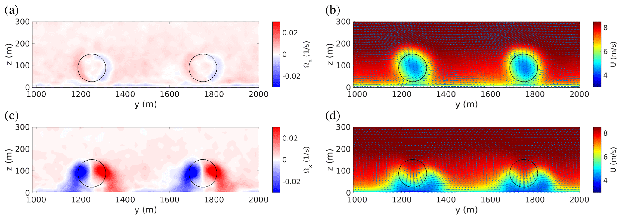
Figure B1Tilt control: cross-stream view of the mean streamwise vorticity and velocity fields obtained by using the ADMC turbine model in the baseline case, where all turbines are operated at with no tilt or yaw (a, b) and with upwind turbines tilted by and operated at (c, d). The streamwise vorticity fields (a, c) are extracted 3D downstream of the first turbine row, while the streamwise velocity fields (b, d) are extracted upstream of the second row of turbines.
First a baseline case has been simulated, with all turbines operated at the reference values , and . Then, a standard tilt-control case has been considered, with upwind-row turbines operated at , (and ), obtaining a power gain %. Finally, overinductive tilt control has been tested by operating the upwind-row turbines at tilted by , obtaining a power gain of ≈27 %.
For the two-row-array layout, therefore, the ADMC model also predicts that power gains obtained by overinductive tilt control are much larger than those obtained by standard tilt control (by ∼240 % for the ADMC turbine model and by ∼330 % with SOWFA's ADM for ). However, the absolute levels of power gains computed with the ADMC model are higher than those computed with SOWFA's ADM turbine model. In this context, the effect of wake rotation appears to be important. In the ADMC model, which applies a uniformly distributed force purely normal to the rotor disk, wake rotation effects are indeed neglected, resulting in a negligible mean axial vorticity in the rotor wake in the baseline case and in almost-symmetric counter-rotating vortices in the tilted case (see Fig. B1a and c). In the ADMC tilted case, therefore, the downwash associated with the tilt-induced streamwise vortices is purely vertical, resulting in a highly efficient displacement of higher-altitude higher-momentum fluid towards the downstream-rotor-swept area (see Fig. B1d). In the case of the more realistic SOWFA ADM turbine model, in contrast, wake rotation effects are fully taken into account, resulting in non-negligible mean axial vorticity in the rotor wake in the baseline case and in strongly non-symmetric counter-rotating vortices in the tilted case (see Fig. 3a and c). In the more realistic case, therefore, the tilt-induced streamwise vortices are associated with an oblique downwash which is less efficient in displacing high-momentum fluid towards the downstream rotors (see Fig. 3d). This explains that lower absolute values of tilt-induced power gains are obtained when wake rotation effects are taken into due account.
Data can be obtained from the author upon request.
The author declares that there is no conflict of interest.
This paper was edited by Johan Meyers and reviewed by Wim Munters and one anonymous referee.
Annoni, J., Gebraad, P. M. O., Scholbrock, A. K., Fleming, P. A., and van Wingerden, J.-W.: Analysis of Axial-Induction-Based Wind Plant Control Using an Engineering and a High-Order Wind Plant Model, Wind Energy, 19, 1135–1150, https://doi.org/10.1002/we.1891, 2016. a
Annoni, J., Scholbrock, A., Churchfield, M., and Fleming, P. A.: Evaluating Tilt for Wind Plants, in: IEEE 2017 American Control Conference (ACC), Seattle, WA, USA, 717–722, https://doi.org/10.23919/ACC.2017.7963037, 2017. a, b
Bastankhah, M. and Porté-Agel, F.: Experimental and Theoretical Study of Wind Turbine Wakes in Yawed Conditions, J. Fluid Mech., 806, 506–541, https://doi.org/10.1017/jfm.2016.595, 2016. a
Bay, C. J., Annoni, J., Martínez-Tossas, L. A., Pao, L. Y., and Johnson, K. E.: Flow Control Leveraging Downwind Rotors for Improved Wind Power Plant Operation, in: IEEE 2019 American Control Conference (ACC), 10–12 July 2019, Philadelphia, Pennsylvania, USA, 2843–2848, 2019. a
Boersma, S., Doekemeijer, B., Gebraad, P., Fleming, P., Annoni, J., Scholbrock, A., Frederik, J., and van Wingerden, J.-W.: A tutorial on control-oriented modeling and control of wind farms, in: IEEE 2017 American Control Conference (ACC), 24–26 May 2017, Seattle, Washington, D.C., USA, 1–18, https://doi.org/10.23919/ACC.2017.7962923, 2017. a, b
Burton, T., Jenkins, N., Sharpe, D., and Bossanyi, E.: Wind energy handbook, John Wiley and Sons, Chichester, UK, 2001. a
Calaf, M., Meneveau, C., and Meyers, J.: Large Eddy Simulation Study of Fully Developed Wind-Turbine Array Boundary Layers, Phys. Fluids, 22, 015110, https://doi.org/10.1063/1.3291077, 2010. a
Campagnolo, F., Petrović, V., Schreiber, J., Nanos, E. M., Croce, A., and Bottasso, C. L.: Wind Tunnel Testing of a Closed-Loop Wake Deflection Controller for Wind Farm Power Maximization, J. Phys. Conf. Ser., 753, 032006, https://doi.org/10.1088/1742-6596/753/3/032006, 2016. a
Churchfield, M. J., Lee, S., Michalakes, J., and Moriarty, P. J.: A Numerical Study of the Effects of Atmospheric and Wake Turbulence on Wind Turbine Dynamics, J. Turbul., 13, N14, https://doi.org/10.1080/14685248.2012.668191, 2012. a, b, c, d, e, f, g
Cossu, C.: Replacing wakes with streaks in wind turbine arrays, Wind Energy, https://doi.org/10.1002/we.2577, in press, 2020a. a, b, c, d, e, f, g
Cossu, C.: Evaluation of tilt control for wind-turbine arrays in the atmospheric boundary layer, Wind Energ. Sci. Discuss. [preprint], https://doi.org/10.5194/wes-2020-106, in review, 2020b. a, b, c, d, e, f, g, h, i, j
Dahlberg, J. Å. and Medici, D.: Potential improvement of wind turbine array efficiency by active wake control (AWC), in: Proc. European Wind Energy Conference, European Wind Energy Association, Madrid, Spain, 2003. a
Fleming, P., Gebraad, P. M., Lee, S., van Wingerden, J.-W., Johnson, K., Churchfield, M., Michalakes, J., Spalart, P., and Moriarty, P.: Simulation Comparison of Wake Mitigation Control Strategies for a Two-Turbine Case, Wind Energy, 18, 2135–2143, https://doi.org/10.1002/we.1810, 2015. a, b, c, d, e
Fleming, P. A., Gebraad, P. M., Lee, S., van Wingerden, J.-W., Johnson, K., Churchfield, M., Michalakes, J., Spalart, P., and Moriarty, P.: Evaluating Techniques for Redirecting Turbine Wakes Using SOWFA, Renew. Energ., 70, 211–218, https://doi.org/10.1016/j.renene.2014.02.015, 2014. a, b
Goit, J. P. and Meyers, J.: Optimal Control of Energy Extraction in Wind-Farm Boundary Layers, J. Fluid Mech., 768, 5–50, https://doi.org/10.1017/jfm.2015.70, 2015. a, b
Howland, M. F., Bossuyt, J., Martínez-Tossas, L. A., Meyers, J., and Meneveau, C.: Wake Structure in Actuator Disk Models of Wind Turbines in Yaw under Uniform Inflow Conditions, J. Renew. Sustain. Energ., 8, 043301, https://doi.org/10.1063/1.4955091, 2016. a, b
Jasak, H.: OpenFOAM: open source CFD in research and industry, Int. J. Nav. Arch. Ocean, 1, 89–94, 2009. a, b
Jiménez, A., Crespo, A., and Migoya, E.: Application of a LES Technique to Characterize the Wake Deflection of a Wind Turbine in Yaw, Wind Energy, 13, 559–572, https://doi.org/10.1002/we.380, 2010. a, b
Jonkman, J., Butterfield, S., Musial, W., and Scott, G.: Definition of a 5-MW reference wind turbine for offshore system development, Technical Paper NREL/TP-500-38060, NREL – National Renewable Energy Lab., Golden, CO, USA, 2009. a, b, c
Keating, A., Piomelli, U., Balaras, E., and Kaltenbach, H.-J.: A priori and a posteriori tests of inflow conditions for large-eddy simulation, Phys. Fluids, 16, 4696–4712, https://doi.org/10.1063/1.1811672, 2004. a
Knudsen, T., Bak, T., and Svenstrup, M.: Survey of wind farm control-power and fatigue optimization: Survey of wind farm control, Wind Energy, 18, 1333–1351, https://doi.org/10.1002/we.1760, 2015. a, b
Martínez-Tossas, L. and Leonardi, S.: Wind Turbine Modeling for Computational Fluid Dynamics, Subcontract Report NREL/SR-5000-55054, US National Renewable Energy Laboratory, Golden, CO, USA, 2013. a
Medici, D. and Alfredsson, P. H.: Measurements on a Wind Turbine Wake: 3D Effects and Bluff Body Vortex Shedding, Wind Energy, 9, 219–236, https://doi.org/10.1002/we.156, 2006. a
Munters, W. and Meyers, J.: An Optimal Control Framework for Dynamic Induction Control of Wind Farms and Their Interaction with the Atmospheric Boundary Layer, Philos. T. Roy. Soc. A, 375, 20160100, https://doi.org/10.1098/rsta.2016.0100, 2017. a, b
Munters, W. and Meyers, J.: Optimal Dynamic Induction and Yaw Control of Wind Farms: Effects of Turbine Spacing and Layout, J. Phys. Conf. Ser., 1037, 032015, https://doi.org/10.1088/1742-6596/1037/3/032015, 2018a. a, b
Munters, W. and Meyers, J.: Dynamic Strategies for Yaw and Induction Control of Wind Farms Based on Large-Eddy Simulation and Optimization, Energies, 11, 177, https://doi.org/10.3390/en11010177, 2018b. a, b, c
Nanos, E. M., Letizia, S., Barreiro, D. J., Wang, C., Rotea, M., Iungo, V. I., and Bottasso, C. L.: Vertical wake deflection for offshore floating wind turbines by differential ballast control, J. Phys. Conf. Ser., 1618, 022047, https://doi.org/10.1088/1742-6596/1618/2/022047, 2020. a
OpenCFD: OpenFOAM – The Open Source CFD Toolbox – User's Guide, 2.4 Edn., OpenCFD Ltd., UK, available at: http://www.openfoam.org (last access: 22 May 2015), 2011. a, b
Park, J. and Law, K. H.: Cooperative Wind Turbine Control for Maximizing Wind Farm Power Using Sequential Convex Programming, Energ. Convers. Manage., 101, 295–316, https://doi.org/10.1016/j.enconman.2015.05.031, 2015. a, b, c
Porté-Agel, F., Bastankhah, M., and Shamsoddin, S.: Wind-Turbine and Wind-Farm Flows: A Review, Bound.-Lay. Meteorol., 174, 1–59, https://doi.org/10.1007/s10546-019-00473-0, 2019. a
Schumann, U.: Subgrid scale model for finite difference simulations of turbulent flows in plane channels and annuli, J. Comput. Phys., 18, 376–404, https://doi.org/10.1016/0021-9991(75)90093-5, 1975. a
Shapiro, C. R., Gayme, D. F., and Meneveau, C.: Modelling Yawed Wind Turbine Wakes: A Lifting Line Approach, J. Fluid Mech., 841, R1, https://doi.org/10.1017/jfm.2018.75, 2018. a
Smagorinsky, J.: General circulation experiments with the primitive equations: I. The basic experiment, Mon. Weather Rev., 91, 99–164, https://doi.org/10.1175/1520-0493(1963)091<0099:GCEWTP>2.3.CO;2, 1963. a
Sørensen, J. N.: Aerodynamic Aspects of Wind Energy Conversion, Annu. Rev. Fluid Mech., 43, 427–448, https://doi.org/10.1146/annurev-fluid-122109-160801, 2011. a
Sørensen, J. N. and Shen, W. Z.: Numerical Modeling of Wind Turbine Wakes, J. Fluids Eng.-T. ASME, 124, 393–399, https://doi.org/10.1115/1.1471361, 2002. a
Steinbuch, M., De Boer, W., Bosgra, O., Peeters, S., and Ploeg, J.: Optimal control of wind power plants, J. Wind Eng. Indust. Aerodynam., 27, 237–246, 1988. a
Stevens, R. J. and Meneveau, C.: Flow Structure and Turbulence in Wind Farms, Annu. Rev. Fluid Mech., 49, 311–339, https://doi.org/10.1146/annurev-fluid-010816-060206, 2017. a
Strickland, J. M. I. and Stevens, R. J. A. M.: Effect of Thrust Coefficient on the Flow Blockage Effects in Closely-Spaced Spanwise-Infinite Turbine Arrays, J. Phys. Conf. Ser., 1618, 062069, https://doi.org/10.1088/1742-6596/1618/6/062069, 2020. a
Tabor, G. R. and Baba-Ahmadi, M. H.: Inlet conditions for large eddy simulation: A review, Comput. Fluids, 39, 553–567, https://doi.org/10.1016/j.compfluid.2009.10.007, 2010. a
This might be related to blockage effects which induce an increase with in the power produced by an (upwind) spanwise-periodic row of turbines as shown by Strickland and Stevens (2020), and it is not surprising given that, for the NREL5 turbine, corresponds by design to the maximum CP (at the optimal tip speed ratio) for an isolated non-tilted turbine but not necessarily so when .