


Abstract
Circular-ribbon flares (CFs) are a special type of solar flares owing to their particular magnetic topology. In this paper, we conducted a comprehensive statistical analysis of 134 CFs from 2011 September to 2017 June, including 4 B-class, 82 C-class, 40 M-class, and 8 X-class flares. The flares were observed by the Atmospheric Imaging Assembly on board the Solar Dynamics Observatory spacecraft. The physical properties of CFs are derived, including the location, area (ACF), equivalent radius (rCF) assuming a semispherical fan dome, lifetime (τCF), and peak soft X-ray (SXR) flux in 1–8 Å. It is found that all CFs are located in active regions, with the latitudes between −30° and 30°. The distributions of areas and lifetimes could be fitted with a lognormal function. There is a positive correlation between the lifetime and area. The peak SXR flux in 1–8 Å is well in accord with a power-law distribution with an index of −1.42. For the 134 CFs, 57% of them are accompanied by remote brightenings or ribbons. A positive correlation exists between the total length (LRB) and average distance (DRB) of remote brightenings. About 47% and 51% of the 134 CFs are related to type III radio bursts and jets, respectively. The association rates are independent of flare energies. About 38% of CFs are related to minifilament eruptions, and the association rates increase with flare classes. Only 28% of CFs are related to coronal mass ejections (CMEs), meaning that a majority of them are confined rather than eruptive events. There is a positive correlation between the CME speed and peak SXR flux in 1–8 Å, and faster CMEs tend to be wider.
Export citation and abstract BibTeX RIS

Original content from this work may be used under the terms of the Creative Commons Attribution 4.0 licence. Any further distribution of this work must maintain attribution to the author(s) and the title of the work, journal citation and DOI.
1. Introduction
Since their first discovery in 1859 (Carrington 1859), solar flares have been observed and studied extensively (see Fletcher et al. 2011; Shibata & Magara 2011, and references therein). According to the classical two-dimensional (2D) flare model, i.e., the CSHKP model (Carmichael 1964; Sturrock 1966; Hirayama 1974; Kopp & Pneuman 1976), when high-energy electrons accelerated by magnetic reconnection propagate downward along the reconnected flare loops and hit the chromosphere, the localized plasmas at the footpoints are impulsively heated, forming two bright and elongated ribbons observed in ultraviolet (UV), extreme-ultraviolet (EUV), and Hα wavelengths (Ji et al. 2006; Jing et al. 2016). In most cases, the ribbons separate due to continuing reconnection (Qiu et al. 2002). Aulanier et al. (2012) and Janvier et al. (2013) extended the 2D standard model to three dimensions to interpret the flare ribbons taking on double-J shapes.
Apart from the typical two-ribbon flares, there is another class of flares, i.e., circular-ribbon flares (CFs), whose ribbons are elliptical or circular (Masson et al. 2009). It is generally believed that the three-dimensional (3D) magnetic configuration of CFs is composed of a null point and the associated dome-shaped fan-spine structure in the corona (e.g., Reid et al. 2012; Wang & Liu 2012; Jiang et al. 2013; Sun et al. 2013; Vemareddy & Wiegelmann 2014; Joshi et al. 2015, 2021; Liu et al. 2015; Zhang et al. 2015, 2021; Mitra & Joshi 2021). Sometimes, the outer spine is embedded in a thin quasi-separatrix layer (Demoulin et al. 1996) where magnetic connectivity changes rapidly (Masson et al. 2009; Yang et al. 2015; Li et al. 2018). Magnetic reconnection preferentially occurs near the null point (Pontin et al. 2007; Priest & Pontin 2009; Pontin et al. 2013; Yang et al. 2020), and the closed ribbon is related to the intersection between the chromosphere and fan surface. Meanwhile, a shorter ribbon inside the closed ribbon is believed to be the intersection between the chromosphere and inner spine. The sizes of circular ribbons range from ∼30'' (Wang & Liu 2012; Hao et al. 2017) to several 100'' (Liu et al. 2013; Joshi et al. 2017; Chen et al. 2019; Hou et al. 2019; Lee et al. 2020). The brightening of circular flare ribbons is not always simultaneous, but sequential in some cases, which is probably caused by slip-running reconnection (Aulanier et al. 2007). The direction of brightening could be clockwise (Shen et al. 2019) or counterclockwise (Masson et al. 2009; Li et al. 2017, 2018; Xu et al. 2017). Interestingly, Zhang et al. (2020) reported fast degradation of a circular ribbon at speeds of 30–70 km s−1 on 2014 August 24. Remote brightenings are frequently observed adjacent to the main flare site as a result of energy transport along the outer spine (Masson et al. 2009; Zhang et al. 2015; Hernandez-Perez et al. 2017; Li et al. 2017; Masson et al. 2017; Devi et al. 2020; Joshi et al. 2021). Extended remote brightenings with a length of ∼400'' are investigated by Liu et al. (2020).
CFs are usually triggered by filament eruptions (Joshi et al. 2015; Xu et al. 2017; Song et al. 2018; Yang et al. 2020), which may also generate coronal jets (Wang & Liu 2012; Zhang et al. 2016a, 2021; Joshi et al. 2018; Li & Yang 2019; Zhang & Ni 2019; Zhang 2020; Dai et al. 2021) or drive coronal mass ejections (CMEs; Sun et al. 2013; Joshi et al. 2015, 2017; Liu et al. 2019, 2020). CFs show similar dynamics to those of two-ribbon flares. Explosive chromospheric evaporation was detected in a C4.2-class flare by the Interface Region Imaging Spectrograph (De Pontieu et al. 2014) on 2015 October 16 (Zhang et al. 2016a). The estimated energy flux of nonthermal electrons is adequate to account for the explosive evaporation. Imaging observation of converging hot ( ) plasma in a postflare loop is considered as direct evidence of chromospheric evaporation during the impulsive phase of a flare (Zhang et al. 2019a). Redshifts of a few 10 km s−1 in the low-temperature emission lines (e.g., Si iv) are clear indications of chromospheric condensation at the circular flare ribbons (Zhang et al. 2016b, 2021). Besides, quasiperiodic pulsations (QPPs; Zimovets et al. 2021) produced by intermittent magnetic reconnections are identified in CFs (Kumar et al. 2015, 2016; Zhang et al. 2016b; Chen et al. 2019; Kashapova et al. 2020; Lee et al. 2020; Li et al. 2020; Ning et al. 2022). The periods are between 20 s and 4 minutes in most cases. CFs are also accompanied by type III radio bursts (Zhang et al. 2016b, 2021) or type IV radio continuum emission (Chen et al. 2019). The total energies of CFs can reach up to 1031–1033 erg. Zhang et al. (2019b) calculated various energy components in two successive M1.8-class CFs in NOAA active region (AR) 12434, including the peak thermal energy, nonthermal energy in flare-accelerated electrons, total radiative loss of the hot plasma, and radiative energy in 1–8 Å and 1–70 Å. It is revealed that the energy partitions in two flares are similar, and the heating requirement consisting of the peak thermal energy and radiative loss could sufficiently be supplied by the nonthermal energy. Furthermore, Cai et al. (2021) investigated four confined CFs in detail, finding that the values of energy components increase systematically with flare classes. The ratio of nonthermal energy to magnetic free energy may provide a key factor for discriminating confined flares from eruptive ones.
So far, CFs have become a topic of great interest due to their particular configurations. However, statistical investigation of CFs is rare compared to two-ribbon flares (e.g., Crosby et al. 1993; Temmer et al. 2001; Veronig et al. 2002; Yashiro et al. 2006; Li et al. 2021; Lu et al. 2021) or microflares (Christe et al. 2008; Hannah et al. 2008). Song & Tian (2018) performed a statistical investigation of 90 CFs observed from 2010 June to 2017 December, finding that the occurrence rate of white-light (WL) flares increases with flare class. Moreover, the flares with WL enhancement have shorter durations, smaller sizes, stronger electric current, and more complicated magnetic fields. Nevertheless, a comprehensive study of the physical properties of CFs and related phenomena is scarce. In this paper, we carry out a statistical analysis of 134 CFs, including 4 B-class, 82 C-class, 40 M-class, and 8 X-class CFs (see Table 1). The paper is organized as follows. We describe the data analysis in Section 2. Statistical properties are presented in Section 3. Finally, a brief conclusion and discussion are given in Section 4.
Table 1. List of 134 Circular-ribbon Flares
| No. | NOAA | Date | GOES | Peak Flux | Location | τCF | ACF | LRB/DRB | Jet | Type III | FE | VCME | WCME |
|---|---|---|---|---|---|---|---|---|---|---|---|---|---|
| AR | Class | (W m−2) | (min) | (Mm2) | (Mm/Mm) | (km s−1) | (deg) | ||||||
| 1 | 11283 | 2011 Sep 6 | M5.3 | 5.39E-05 | N15W09 | 94 | 2823.5 | 28.0/117.6 | No | No | No | 782 | 360 |
| 2 | 11283 | 2011 Sep 6 | X2.1 | 2.16E-04 | N15W20 | 35 | 2594.8 | 65.8/105.6 | No | No | Yes | 575 | 360 |
| 3 | 11283 | 2011 Sep 7 | X1.8 | 1.80E-04 | N16W32 | 81 | 1983.0 | 193.4/76.3 | No | No | Yes | 792 | 167 |
| 4 | 11283 | 2011 Sep 8 | M6.7 | 6.77E-05 | N16W42 | 64 | 2439.6 | 103.0/77.9 | No | No | Yes | 983 | 281 |
| 5 | 11324 | 2011 Oct 22 | C4.1 | 4.12E-06 | N11E24 | 34 | 1616.9 | 19.3/63.7 | No | No | No | ⋯ | ⋯ |
| 6 | 11339 | 2011 Nov 3 | X1.9 | 2.04E-04 | N21E64 | 102 | 725.8 | 65.2/35.7 | No | No | Yes | 991 | 360 |
| 7 | 11339 | 2011 Nov 6 | M1.4 | 1.45E-05 | N21E32 | 94 | 581.7 | 14.1/70.7 | No | Yes | No | ⋯ | ⋯ |
| 8 | 11339 | 2011 Nov 6 | C8.8 | 9.10E-06 | N21E30 | 43 | 542.6 | 35.7/67.5 | No | No | No | ⋯ | ⋯ |
| 9 | 11339 | 2011 Nov 6 | C5.3 | 5.42E-06 | N21E28 | 113 | 422.8 | 33.2/72.2 | No | No | No | ⋯ | ⋯ |
| 10 | 11346 | 2011 Nov 15 | M1.9 | 1.97E-05 | S19E32 | 99 | 1165.3 | 144.8/86.1 | Yes | Yes | No | 163 | 80 |
| 11 | 11346 | 2011 Nov 16 | C2.8 | 2.91E-06 | S18E19 | 31 | 315.8 | 91.3/75.2 | Yes | No | Yes | ⋯ | ⋯ |
| 12 | 11346 | 2011 Nov 16 | C2.9 | 3.01E-06 | S18E16 | 37 | 345.1 | 59.8/72.7 | Yes | No | Yes | ⋯ | ⋯ |
| 13 | 11346 | 2011 Nov 16 | C5.0 | 5.14E-06 | S19E12 | 59 | 1181.3 | 121.8/118.3 | Yes | No | Yes | ⋯ | ⋯ |
| 14 | 11346 | 2011 Nov 17 | C2.0 | 2.05E-06 | S19E04 | 59 | 1278.9 | 134.1/86.7 | No | No | No | ⋯ | ⋯ |
| 15 | 11476 | 2012 May 6 | C1.4 | 1.43E-06 | N11E72 | 12 | 354.0 | ⋯ | No | No | No | ⋯ | ⋯ |
| 16 | 11476 | 2012 May 7 | C4.0 | 4.17E-06 | N11E61 | 73 | 598.9 | 39.6/54.9 | Yes | Yes | No | ⋯ | ⋯ |
| 17 | 11476 | 2012 May 7 | C7.9 | 8.07E-06 | N13E60 | 24 | 428.0 | 78.3/67.7 | No | Yes | No | ⋯ | ⋯ |
| 18 | 11476 | 2012 May 7 | C7.4 | 7.67E-06 | N13E56 | 59 | 445.1 | ⋯ | No | Yes | No | ⋯ | ⋯ |
| 19 | 11476 | 2012 May 8 | M1.4 | 1.48E-05 | N13E45 | 92 | 545.6 | 60.1/92.3 | No | Yes | Yes | ⋯ | ⋯ |
| 20 | 11476 | 2012 May 9 | M4.7 | 4.86E-05 | N13E32 | 61 | 569.4 | 79.2/91.7 | Yes | No | Yes | ⋯ | ⋯ |
| 21 | 11476 | 2012 May 9 | C1.5 | 1.55E-06 | N13E28 | 11 | 424.1 | ⋯ | Yes | No | No | ⋯ | ⋯ |
| 22 | 11476 | 2012 May 9 | M4.1 | 4.16E-05 | N13E27 | 66 | 797.7 | 128.2/97.4 | Yes | No | Yes | ⋯ | ⋯ |
| 23 | 11476 | 2012 May 10 | M5.7 | 6.00E-05 | N13E23 | 101 | 1188.3 | 119.5/86.2 | Yes | Yes | Yes | ⋯ | ⋯ |
| 24 | 11476 | 2012 May 10 | M1.7 | 1.84E-05 | N13E14 | 83 | 979.8 | 82.5/98.5 | Yes | No | Yes | ⋯ | ⋯ |
| 25 | 11476 | 2012 May 11 | C3.1 | 3.15E-06 | N14E13 | 20 | 816.2 | ⋯ | Yes | Yes | No | ⋯ | ⋯ |
| 26 | 11476 | 2012 May 11 | C3.5 | 3.69E-06 | N14E06 | 11 | 485.9 | ⋯ | Yes | Yes | No | ⋯ | ⋯ |
| 27 | 11476 | 2012 May 14 | C2.5 | 3.02E-06 | N08W46 | 36 | 339.8 | 27.4/41.3 | Yes | Yes | No | 551 | 48 |
| 28 | 11598 | 2012 Oct 22 | M5.0 | 5.10E-05 | S13E64 | 113 | 1343.4 | ⋯ | No | No | No | ⋯ | ⋯ |
| 29 | 11598 | 2012 Oct 23 | X1.8 | 1.71E-04 | S13E59 | 108 | 1423.2 | ⋯ | No | No | No | ⋯ | ⋯ |
| 30 | 11652 | 2013 Jan 8 | C1.8 | 1.92E-06 | N21E56 | 25 | 343.5 | ⋯ | Yes | No | No | ⋯ | ⋯ |
| 31 | 11652 | 2013 Jan 12 | C3.1 | 3.29E-06 | N19W17 | 4 | 182.1 | ⋯ | No | No | No | ⋯ | ⋯ |
| 32 | 11652 | 2013 Jan 13 | M1.0 | 1.25E-05 | N18W18 | 16 | 311.1 | ⋯ | Yes | Yes | No | ⋯ | ⋯ |
| 33 | 11652 | 2013 Jan 13 | C2.7 | 2.83E-06 | N18W22 | 20 | 213.6 | ⋯ | No | Yes | No | ⋯ | ⋯ |
| 34 | 11652 | 2013 Jan 13 | M1.7 | 1.86E-05 | N18W22 | 9 | 362.1 | 56.2/115.2 | Yes | Yes | Yes | 696 | 46 |
| 35 | 11652 | 2013 Jan 14 | C6.5 | 6.75E-06 | N18W31 | 14 | 438.4 | 24.2/66.6 | No | No | No | ⋯ | ⋯ |
| 36 | 11669 | 2013 Feb 5 | B6.6 | 6.92E-07 | N09E64 | 63 | 1191.6 | ⋯ | Yes | No | Yes | ⋯ | ⋯ |
| 37 | 11669 | 2013 Feb 5 | C6.3 | 6.51E-06 | N08E62 | 25 | 1649.0 | ⋯ | Yes | Yes | Yes | 444 | 66 |
| 38 | 11675 | 2013 Feb 17 | M1.9 | 2.80E-05 | N12E21 | 10 | 183.0 | 7.0/47.7 | Yes | Yes | No | ⋯ | ⋯ |
| 39 | 11689 | 2013 Mar 12 | C3.6 | 3.87E-06 | S20W40 | 28 | 154.2 | 21.3/82.8 | Yes | No | Yes | ⋯ | ⋯ |
| 40 | 11731 | 2013 Apr 28 | C3.7 | 4.07E-06 | N09E28 | 9 | 335.2 | ⋯ | Yes | Yes | No | ⋯ | ⋯ |
| 41 | 11731 | 2013 Apr 28 | C1.8 | 1.96E-06 | N09E28 | 8 | 433.3 | ⋯ | Yes | No | Yes | ⋯ | ⋯ |
| 42 | 11731 | 2013 Apr 28 | C3.6 | 4.02E-06 | N09E27 | 13 | 133.2 | ⋯ | Yes | Yes | No | ⋯ | ⋯ |
| 43 | 11731 | 2013 Apr 29 | C3.0 | 3.06E-06 | N10E14 | 14 | 634.7 | ⋯ | No | Yes | No | 452 | 67 |
| 44 | 11731 | 2013 May 1 | C1.1 | 1.14E-06 | N07W11 | 10 | 160.8 | ⋯ | Yes | No | Yes | ⋯ | ⋯ |
| 45 | 11731 | 2013 May 2 | M1.1 | 1.13E-05 | N11W25 | 43 | 4539.9 | ⋯ | Yes | Yes | Yes | ⋯ | ⋯ |
| 46 | 11890 | 2013 Nov 5 | M2.5 | 2.81E-05 | S16E51 | 12 | 752.7 | 135.3/72.1 | No | Yes | Yes | ⋯ | ⋯ |
| 47 | 11890 | 2013 Nov 5 | X3.3 | 3.85E-04 | S13E45 | 23 | 796.4 | 61.8/79.4 | Yes | Yes | Yes | 562 | 195 |
| 48 | 11890 | 2013 Nov 6 | C8.6 | 8.93E-06 | S13E39 | 17 | 726.7 | ⋯ | Yes | Yes | Yes | ⋯ | ⋯ |
| 49 | 11890 | 2013 Nov 6 | M3.8 | 3.88E-05 | S13E36 | 21 | 701.0 | 169.8/149.8 | No | Yes | Yes | 347 | 122 |
| 50 | 11890 | 2013 Nov 7 | M2.3 | 2.41E-05 | S13E28 | 22 | 727.8 | ⋯ | Yes | No | Yes | ⋯ | ⋯ |
| 51 | 11890 | 2013 Nov 7 | C5.9 | 5.99E-06 | S13E23 | 21 | 697.8 | ⋯ | No | Yes | Yes | ⋯ | ⋯ |
| 52 | 11890 | 2013 Nov 8 | X1.1 | 1.22E-04 | S14E15 | 24 | 1485.7 | 311.1/120.9 | Yes | Yes | Yes | ⋯ | ⋯ |
| 53 | 11890 | 2013 Nov 10 | X1.1 | 1.14E-04 | S15W13 | 33 | 2171.1 | 381.0/119.1 | Yes | Yes | Yes | 682 | 262 |
| 54 | 11890 | 2013 Nov 10 | C3.1 | 3.17E-06 | S15W19 | 56 | 306.5 | ⋯ | Yes | Yes | No | ⋯ | ⋯ |
| 55 | 11890 | 2013 Nov 11 | C6.4 | 6.59E-06 | S15W26 | 33 | 521.0 | 39.6/110.1 | No | No | Yes | ⋯ | ⋯ |
| 56 | 11890 | 2013 Nov 11 | C7.8 | 8.18E-06 | S14W24 | 12 | 642.7 | 12.5/128.0 | Yes | No | No | 533 | 40 |
| 57 | 11890 | 2013 Nov 11 | C5.0 | 5.09E-06 | S14W34 | 25 | 1020.6 | 16.7/105.6 | Yes | No | No | ⋯ | ⋯ |
| 58 | 11890 | 2013 Nov 12 | C3.1 | 3.22E-06 | S11W60 | 12 | 346.8 | ⋯ | Yes | No | No | 365 | 24 |
| 59 | 11890 | 2013 Nov 13 | C6.5 | 6.75E-06 | S14W54 | 144 | 877.3 | 50.2/84.0 | Yes | Yes | No | ⋯ | ⋯ |
| 60 | 11936 | 2013 Dec 25 | C1.7 | 1.79E-06 | S18E51 | 58 | 621.2 | ⋯ | No | No | No | 254 | 72 |
| 61 | 11936 | 2013 Dec 27 | C4.4 | 4.52E-06 | S17E23 | 35 | 507.7 | ⋯ | Yes | Yes | No | 305 | 67 |
| 62 | 11936 | 2013 Dec 28 | C3.0 | 3.08E-06 | S17E09 | 38 | 931.1 | 32.3/49.2 | No | Yes | Yes | ⋯ | ⋯ |
| 63 | 11936 | 2013 Dec 28 | C9.3 | 9.44E-06 | S17E06 | 100 | 684.1 | 24.5/45.0 | No | No | No | ⋯ | ⋯ |
| 64 | 11936 | 2013 Dec 29 | C3.1 | 3.17E-06 | S17W01 | 9 | 451.6 | ⋯ | No | Yes | No | ⋯ | ⋯ |
| 65 | 11936 | 2013 Dec 29 | M3.1 | 3.23E-05 | S17W02 | 65 | 828.1 | 10.4/48.6 | Yes | Yes | Yes | ⋯ | ⋯ |
| 66 | 11936 | 2013 Dec 29 | C5.1 | 5.26E-06 | S16W06 | 60 | 831.7 | 7.7/48.9 | No | No | No | ⋯ | ⋯ |
| 67 | 11936 | 2013 Dec 29 | C1.9 | 2.02E-06 | S16W07 | 20 | 364.2 | ⋯ | No | No | No | ⋯ | ⋯ |
| 68 | 11936 | 2013 Dec 29 | C5.4 | 5.57E-06 | S16W09 | 61 | 647.6 | 218.6/103.0 | Yes | No | No | ⋯ | ⋯ |
| 69 | 11936 | 2013 Dec 31 | M6.4 | 6.49E-05 | S17W36 | 128 | 2582.3 | 240.5/88.9 | No | Yes | Yes | ⋯ | ⋯ |
| 70 | 11936 | 2014 Jan 1 | M9.9 | 1.00E-04 | S16W47 | 55 | 4240.8 | 116.8/84.2 | No | No | Yes | 326 | 113 |
| 71 | 11991 | 2014 Feb 27 | C6.8 | 7.03E-06 | S22E58 | 21 | 461.9 | 34.3/67.5 | Yes | Yes | No | 120 | 55 |
| 72 | 11991 | 2014 Feb 28 | M1.1 | 1.22E-05 | S23E52 | 61 | 333.6 | 123.5/59.6 | Yes | No | No | ⋯ | ⋯ |
| 73 | 11991 | 2014 Mar 5 | C4.8 | 5.04E-06 | S27W07 | 24 | 248.4 | ⋯ | Yes | No | Yes | ⋯ | ⋯ |
| 74 | 11991 | 2014 Mar 5 | C2.8 | 2.90E-06 | S27W08 | 79 | 248.9 | ⋯ | Yes | No | No | ⋯ | ⋯ |
| 75 | 11991 | 2014 Mar 5 | M1.0 | 1.06E-05 | S27W08 | 7 | 318.7 | 27.8/89.8 | Yes | No | No | ⋯ | ⋯ |
| 76 | 12017 | 2014 Mar 28 | M2.0 | 2.06E-05 | N12W21 | 42 | 2256.6 | ⋯ | Yes | Yes | Yes | 260 | 31 |
| 77 | 12017 | 2014 Mar 28 | M2.6 | 2.67E-05 | N12W24 | 37 | 2150.1 | ⋯ | Yes | Yes | Yes | 514 | 138 |
| 78 | 12017 | 2014 Mar 29 | X1.0 | 1.02E-04 | N11W33 | 64 | 2030.6 | 28.8/65.7 | Yes | No | Yes | 528 | 360 |
| 79 | 12031 | 2014 Apr 6 | C3.8 | 3.96E-06 | N03W23 | 66 | 1476.1 | ⋯ | No | No | Yes | ⋯ | ⋯ |
| 80 | 12035 | 2014 Apr 15 | C8.6 | 9.08E-06 | S15E25 | 21 | 1030.0 | 12.5/93.6 | Yes | Yes | Yes | 274 | 27 |
| 81 | 12035 | 2014 Apr 15 | C7.3 | 7.92E-06 | S14E21 | 47 | 2640.7 | ⋯ | No | Yes | Yes | 360 | 179 |
| 82 | 12035 | 2014 Apr 16 | M1.0 | 1.04E-05 | S13E08 | 33 | 1920.4 | 150.4/148.0 | Yes | Yes | Yes | 764 | 61 |
| 83 | 12036 | 2014 Apr 18 | M7.3 | 7.32E-05 | S17W29 | 138 | 23961.9 | ⋯ | No | Yes | No | 1203 | 360 |
| 84 | 12087 | 2014 Jun 13 | M2.6 | 2.66E-05 | S20E40 | 71 | 1004.1 | 33.0/91.5 | Yes | Yes | No | 370 | 42 |
| 85 | 12087 | 2014 Jun 13 | C9.0 | 9.17E-06 | S19E32 | 26 | 909.3 | 16.0/79.3 | No | Yes | No | 605 | 31 |
| 86 | 12127 | 2014 Jul 31 | C1.3 | 1.44E-06 | S07E32 | 8 | 193.0 | ⋯ | Yes | Yes | Yes | 458 | 77 |
| 87 | 12146 | 2014 Aug 22 | C2.2 | 2.22E-06 | N11E01 | 88 | 3099.4 | ⋯ | No | Yes | No | ⋯ | ⋯ |
| 88 | 12148 | 2014 Aug 22 | C6.6 | 6.71E-06 | N08W32 | 27 | 394.4 | 7.2/87.4 | Yes | No | No | ⋯ | ⋯ |
| 89 | 12157 | 2014 Sep 13 | C3.7 | 3.92E-06 | S16W39 | 34 | 315.3 | 17.5/35.3 | No | Yes | No | ⋯ | ⋯ |
| 90 | 12192 | 2014 Oct 20 | M1.4 | 1.57E-05 | S15E46 | 21 | 508.6 | ⋯ | Yes | Yes | No | ⋯ | ⋯ |
| 91 | 12201 | 2014 Nov 3 | C4.2 | 4.32E-06 | S03E21 | 26 | 987.7 | ⋯ | Yes | Yes | Yes | ⋯ | ⋯ |
| 92 | 12227 | 2014 Dec 13 | C4.0 | 4.10E-06 | S03W66 | 36 | 1040.3 | ⋯ | Yes | Yes | Yes | 198 | 74 |
| 93 | 12242 | 2014 Dec 17 | M8.7 | 8.76E-05 | S22E09 | 162 | 13165.7 | 358.8/186.2 | No | No | No | 587 | 360 |
| 94 | 12266 | 2015 Jan 19 | C3.3 | 3.41E-06 | S06E04 | 23 | 415.0 | ⋯ | Yes | No | Yes | ⋯ | ⋯ |
| 95 | 12268 | 2015 Jan 29 | C8.2 | 8.32E-06 | S12W03 | 119 | 2071.2 | 26.9/129.6 | No | No | No | ⋯ | ⋯ |
| 96 | 12268 | 2015 Jan 29 | M2.1 | 2.12E-05 | S11W07 | 99 | 3042.0 | 30.9/116.0 | No | Yes | No | ⋯ | ⋯ |
| 97 | 12268 | 2015 Jan 29 | C6.4 | 6.43E-06 | S11W11 | 191 | 3235.1 | 31.2/112.5 | No | No | No | ⋯ | ⋯ |
| 98 | 12268 | 2015 Jan 30 | M2.0 | 2.09E-05 | S12W15 | 205 | 4132.4 | 37.3/104.7 | No | No | No | ⋯ | ⋯ |
| 99 | 12268 | 2015 Jan 30 | M1.7 | 1.77E-05 | S11W17 | 116 | 4783.7 | 87.8/87.2 | No | No | No | ⋯ | ⋯ |
| 100 | 12276 | 2015 Jan 30 | C3.8 | 3.84E-06 | S07E09 | 88 | 957.5 | ⋯ | Yes | Yes | Yes | ⋯ | ⋯ |
| 101 | 12277 | 2015 Feb 3 | C3.9 | 3.98E-06 | N07W04 | 43 | 599.0 | 14.2/77.4 | Yes | Yes | Yes | ⋯ | ⋯ |
| 102 | 12297 | 2015 Mar 9 | C9.1 | 9.40E-06 | S15E44 | 33 | 771.9 | 34.5/52.8 | Yes | Yes | Yes | 583 | 155 |
| 103 | 12297 | 2015 Mar 10 | M5.1 | 5.29E-05 | S14E39 | 25 | 1182.6 | ⋯ | Yes | Yes | No | 1040 | 360 |
| 104 | 12297 | 2015 Mar 10 | C1.3 | 4.67E-06 | S16E41 | 38 | 574.7 | ⋯ | Yes | Yes | No | ⋯ | ⋯ |
| 105 | 12297 | 2015 Mar 11 | M2.9 | 2.97E-05 | S15E27 | 85 | 591.8 | ⋯ | No | Yes | No | 702 | 160 |
| 106 | 12297 | 2015 Mar 12 | M2.7 | 2.81E-05 | S14E02 | 94 | 828.0 | ⋯ | No | Yes | No | ⋯ | ⋯ |
| 107 | 12297 | 2015 Mar 13 | M1.8 | 1.89E-05 | S14W03 | 80 | 710.5 | ⋯ | Yes | Yes | No | ⋯ | ⋯ |
| 108 | 12297 | 2015 Mar 15 | C2.4 | 2.51E-06 | S17W28 | 16 | 554.1 | ⋯ | Yes | No | Yes | ⋯ | ⋯ |
| 109 | 12297 | 2015 Mar 15 | C1.0 | 1.04E-06 | S17W40 | 21 | 346.6 | ⋯ | Yes | No | No | ⋯ | ⋯ |
| 110 | 12325 | 2015 Apr 16 | C3.3 | 3.37E-06 | N06E51 | 112 | 1177.4 | 12.8/47.5 | No | No | No | ⋯ | ⋯ |
| 111 | 12434 | 2015 Oct 15 | C3.6 | 3.77E-06 | S11E55 | 32 | 417.2 | ⋯ | No | No | No | ⋯ | ⋯ |
| 112 | 12434 | 2015 Oct 15 | C3.9 | 4.07E-06 | S11E53 | 34 | 627.7 | ⋯ | No | No | No | ⋯ | ⋯ |
| 113 | 12434 | 2015 Oct 15 | C3.4 | 3.51E-06 | S11E52 | 49 | 535.3 | ⋯ | No | No | No | ⋯ | ⋯ |
| 114 | 12434 | 2015 Oct 15 | C3.1 | 3.22E-06 | S12E51 | 47 | 440.8 | 29.5/92.2 | No | No | No | 283 | 13 |
| 115 | 12434 | 2015 Oct 15 | M1.1 | 1.21E-05 | S13E50 | 13 | 561.7 | 375.9/178.2 | No | No | No | ⋯ | ⋯ |
| 116 | 12434 | 2015 Oct 16 | C3.4 | 3.58E-06 | S13E45 | 16 | 569.5 | 95.7/167.6 | Yes | Yes | No | ⋯ | ⋯ |
| 117 | 12434 | 2015 Oct 16 | C3.1 | 3.22E-06 | S13E44 | 23 | 563.5 | 281.9/177.0 | No | Yes | No | ⋯ | ⋯ |
| 118 | 12434 | 2015 Oct 16 | M1.1 | 1.14E-05 | S13E46 | 26 | 599.0 | 282.8/177.8 | No | Yes | Yes | ⋯ | ⋯ |
| 119 | 12434 | 2015 Oct 16 | C4.2 | 4.34E-06 | S13E42 | 14 | 608.8 | 262.2/170.7 | Yes | Yes | Yes | 189 | 83 |
| 120 | 12434 | 2015 Oct 24 | C1.3 | 1.35E-06 | S13W73 | 29 | 720.4 | ⋯ | Yes | No | No | ⋯ | ⋯ |
| 121 | 12497 | 2016 Feb 13 | C1.3 | 1.37E-06 | N14W25 | 13 | 241.5 | 29.2/89.2 | No | No | No | ⋯ | ⋯ |
| 122 | 12497 | 2016 Feb 13 | C2.8 | 2.85E-06 | N14W26 | 27 | 281.5 | 25.1/83.1 | Yes | No | No | 278 | 19 |
| 123 | 12497 | 2016 Feb 13 | B8.5 | 8.68E-07 | N14W26 | 26 | 130.3 | ⋯ | No | No | No | ⋯ | ⋯ |
| 124 | 12497 | 2016 Feb 13 | B6.9 | 7.03E-07 | N14W27 | 51 | 123.1 | ⋯ | No | No | No | ⋯ | ⋯ |
| 125 | 12497 | 2016 Feb 13 | M1.8 | 1.88E-05 | N14W29 | 120 | 361.1 | 59.2/72.8 | Yes | No | No | ⋯ | ⋯ |
| 126 | 12497 | 2016 Feb 13 | C1.6 | 1.67E-06 | N14W31 | 26 | 400.8 | 49.0/66.4 | No | No | No | ⋯ | ⋯ |
| 127 | 12497 | 2016 Feb 14 | C3.4 | 3.48E-06 | N14W36 | 70 | 464.8 | 51.7/50.7 | No | No | No | ⋯ | ⋯ |
| 128 | 12497 | 2016 Feb 14 | M1.0 | 1.05E-05 | N14W48 | 39 | 987.2 | 52.7/85.5 | No | No | No | ⋯ | ⋯ |
| 129 | 12497 | 2016 Feb 15 | C3.9 | 3.94E-06 | N14W53 | 31 | 899.1 | 26.2/28.6 | Yes | No | No | ⋯ | ⋯ |
| 130 | 12567 | 2016 Jul 16 | C6.8 | 7.11E-06 | N05E26 | 35 | 260.6 | 19.4/31.4 | No | No | No | ⋯ | ⋯ |
| 131 | 12615 | 2016 Nov 30 | C2.3 | 3.90E-06 | S07E43 | 24 | 127.3 | ⋯ | No | No | No | ⋯ | ⋯ |
| 132 | 12661 | 2017 Jun 3 | C2.1 | 2.16E-06 | N07E56 | 77 | 636.9 | ⋯ | No | Yes | Yes | ⋯ | ⋯ |
| 133 | 12661 | 2017 Jun 3 | C2.5 | 2.67E-06 | N06E53 | 46 | 921.5 | ⋯ | No | Yes | No | ⋯ | ⋯ |
| 134 | 12661 | 2017 Jun 5 | B5.8 | 5.90E-07 | N06E18 | 45 | 155.5 | 6.2/60.5 | No | No | No | ⋯ | ⋯ |
Table 2. Minima, Maxima, Mean Values, and Median Values of the Physical Properties of CFs and the Related Activities
| Parameter | ACF | rCF | τCF | LRB | DRB | VCME | WCME |
|---|---|---|---|---|---|---|---|
| (Mm2) | (Mm) | (minute) | (Mm) | (Mm) | (km s−1) | (deg) | |
| Minimum | 123.1 | 6.3 | 4.0 | 6.2 | 28.6 | 120.0 | 13.0 |
| Maximum | 23,961.9 | 87.3 | 205.0 | 381.0 | 186.2 | 1203.0 | 360.0 |
| Mean | 1214.8 | 16.8 | 49.6 | 84.1 | 89.1 | 516.7 | 143.6 |
| Median | 631.2 | 14.2 | 35.0 | 44.3 | 84.8 | 514.0 | 80.0 |
Download table as: ASCIITypeset image
2. Data Analysis
We searched for CFs observed by the Atmospheric Imaging Assembly (AIA; Lemen et al. 2012) on board the Solar Dynamics Observatory (SDO; Pesnell et al. 2012) from 2011 September to 2017 June. AIA took full-disk images in seven EUV (94, 131, 171, 193, 211, 304, and 335 Å) and two UV (1600 and 1700 Å) wavelengths. The AIA Level 1 data with a time cadence of 12 s and a spatial resolution of 1 2 were calibrated using the standard program aia_prep.pro in the Solar Software. Photospheric line-of-sight (LOS) magnetograms of the flares were observed by the Helioseismic and Magnetic Imager (HMI; Scherrer et al. 2012) on board SDO. The HMI Level 1 data with a time cadence of 45 s and a spatial resolution of 12 were calibrated using the standard program hmi_prep.pro. Soft X-ray (SXR) light curves of CFs in 1–8 Å were recorded by the GOES spacecraft. The associations with remote brightenings, coronal jets, and minifilament eruptions were checked using the EUV observations of AIA. The total lengths of remote brightenings and average distances from the flare centers were calculated. The association with CMEs was examined using the WL observations from the Large Angle and Spectrometric Coronagraph (LASCO; Brueckner et al. 1995) on board the SOHO spacecraft. The LASCO/C2 has a field of view (FOV) of 2–6 R☉. Two databases were used: the CDAW catalog
4
where CMEs are identified manually and the CACTus website
5
where CMEs are recognized automatically (Yashiro et al. 2008). The apparent linear velocities and angular widths of the associated CMEs were analyzed. The relation with type III radio bursts was checked using the radio dynamic spectra recorded by the e-Callisto
6
ground-based stations as well as the WAVES (Bougeret et al. 1995) instrument (0.02–13.825 MHz) on board the WIND spacecraft.
7
2 were calibrated using the standard program aia_prep.pro in the Solar Software. Photospheric line-of-sight (LOS) magnetograms of the flares were observed by the Helioseismic and Magnetic Imager (HMI; Scherrer et al. 2012) on board SDO. The HMI Level 1 data with a time cadence of 45 s and a spatial resolution of 12 were calibrated using the standard program hmi_prep.pro. Soft X-ray (SXR) light curves of CFs in 1–8 Å were recorded by the GOES spacecraft. The associations with remote brightenings, coronal jets, and minifilament eruptions were checked using the EUV observations of AIA. The total lengths of remote brightenings and average distances from the flare centers were calculated. The association with CMEs was examined using the WL observations from the Large Angle and Spectrometric Coronagraph (LASCO; Brueckner et al. 1995) on board the SOHO spacecraft. The LASCO/C2 has a field of view (FOV) of 2–6 R☉. Two databases were used: the CDAW catalog
4
where CMEs are identified manually and the CACTus website
5
where CMEs are recognized automatically (Yashiro et al. 2008). The apparent linear velocities and angular widths of the associated CMEs were analyzed. The relation with type III radio bursts was checked using the radio dynamic spectra recorded by the e-Callisto
6
ground-based stations as well as the WAVES (Bougeret et al. 1995) instrument (0.02–13.825 MHz) on board the WIND spacecraft.
7
3. Statistical Properties
3.1. Location
In Figure 1, the top panels show three images of the C4.2-class flare observed by AIA in 304 Å on 2015 October 16 (Zhang et al. 2016a; Dai et al. 2021). The flare was triggered by a minifilament eruption and was associated with a blowout coronal jet. In panel (a3), the flare ribbon is fitted with an ellipse, whose center is considered as the flare location (S13E42). The middle panels of Figure 1 show 304 Å images of another three cases. The bright ribbons are fitted with a circle and two ellipses, which are drawn with dashed cyan lines. The centers (S22E09, S19E32, and S13E59) of the flares are derived and pointed to by solid arrows. The bottom panels of Figure 1 show the corresponding LOS magnetograms of the three events observed by HMI. The CFs are characterized by a central positive (negative) polarity surrounded by negative (positive) polarities, which is essentially consistent with the fan-spine magnetic structure (Masson et al. 2009; Wang & Liu 2012). Most of the CFs in our sample show similar characteristics. For all 134 events, we fit the circular or quasi-circular ribbons observed in 304 or 1600 Å with a circle or an ellipse. The derived coordinates of CFs in the sixth column of Table 1 agree with those recorded in the GOES flare catalog. 8 In Figure 2(a), the flare centers are marked with colored dots, with cyan (red) dots signifying confined (eruptive) flares. Figure 2(b) shows latitude distribution of the CFs, where 76 (58) of which are located in the southern (northern) hemisphere. It is clear that all CFs are located in ARs like microflares, and the latitudes of CFs are between −30° and 30°. Hence, the distribution of CFs is consistent with the AR belts.

Figure 1. Top panels: three snapshots of the AIA 304 Å images, showing the evolution of the C4.2-class flare in AR 12434 on 2015 October 16. The white arrows point to the accompanying minifilament eruption and coronal jet. In panel (a3), the location and total area of the flare are labeled. The remote brightening is outlined by the cyan line. The total length and average distance between the flare and remote brightening are labeled. Middle panels: additional three cases observed in 304 Å. The flare ribbons are fitted with a circle and two ellipses (dashed cyan lines). The centers are pointed by solid arrows. Bottom panels: corresponding LOS magnetograms of the three events observed by HMI.
Download figure:
Standard image High-resolution image
Figure 2. (a) Locations of the 134 CFs, which are marked with cyan dots (confined flares) and red dots (eruptive flares). The latitudes and longitudes of the Sun are drawn with gray lines. (b) Latitude distribution of the CFs. Positive (negative) latitude means northern (southern) hemisphere.
Download figure:
Standard image High-resolution image3.2. Area
Compared with two-ribbon flares whose ribbons show separation (Qiu et al. 2002) or elongation (Li et al. 2015; Qiu et al. 2017), the outer ribbons of CFs hardly expand. Hence, the area keeps constant. In Figure 1(a3), the apparent area of the C4.2 flare enclosed by the ellipse is ∼452 Mm2. The true area (∼609 Mm2) after deprojection according to the flare longitude is defined as the total area (ACF). In the middle panels of Figure 1, the apparent areas of the three CFs are ∼13,008, ∼985, and ∼739 Mm2. The true areas are estimated to be ∼13,166, ∼1165, and ∼1423 Mm2, respectively. For the 134 CFs, the areas are calculated according to the fitted circles or ellipses, which range from 123 to ∼5000 Mm2 in most cases. Figure 3 shows the distribution of ACF. Note that the areas (13,166 and 23,962 Mm2) of two events significantly exceeding 5000 Mm2 are not taken into account in the histogram. We fit the distribution of ACF with a lognormal function (Zhang et al. 2010):

The curve fitting is performed by using mpfit.pro and the result is superposed with a red line in Figure 3, where μ = 6.51 and σ = 0.66. The minima, maxima, mean values, and median values of the flare areas are listed in Table 2.

Figure 3. Distribution of the flare area. The result of the curve fitting using the lognormal function is superposed with a red line. Two values significantly exceeding 5000 Mm2 are excluded in this plot.
Download figure:
Standard image High-resolution imageWe notice that there is a tendency of increasing area with flare class. In Figure 4(a), the flare areas are divided into three groups of roughly the same amount. In the range of 0–462 Mm2, only 13% (6/45) are M- and X-class CFs. The proportion rises to 36% (16/45) in the range of 462–915 Mm2. Above 915 Mm2, M- and X-class CFs account for 59% (26/44). Therefore, flares with larger magnitudes generally have larger areas. The sample of CFs in our study overlaps with that in Song & Tian (2018). They used an irregularly closed line rather than a circle or an oval to fit the flare ribbon. Although the methods are different, the derived areas of CFs are very close to each other.

Figure 4. Percentages of M- and X-class CFs in different groups of area (a), lifetime (b), total length of remote brightening (c), and average distance of remote brightening (d).
Download figure:
Standard image High-resolution imageIt is widely believed that the magnetic configuration of CFs consists of a null point and the associated dome-shaped fan-spine structure. Assuming that the fan surface is a semisphere (Pariat et al. 2009, 2010), the height of the null point is equivalent to the radius of circular ribbons:

Figure 5 shows the distribution of rCF, which lies in the range of 6–39 Mm with a mean value of ∼16 Mm (the largest two events are excluded). The estimated altitudes of null points are consistent with previous results (e.g., Sun et al. 2013; Xu et al. 2017; Hou et al. 2019; Li & Yang 2019; Yang et al. 2020). Song & Tian (2018) found that WL flares feature smaller areas than normal flares with the same flare magnitude, which is explained by the lower heights of null points where magnetic free energy is released and consequently there are larger energy fluxes in WL flares.

Figure 5. Distribution of the equivalent radius of flare ribbons.
Download figure:
Standard image High-resolution image3.3. Lifetime
We determine the flare lifetime (τCF) using the start and end times. The former refers to the time when the GOES 1–8 Å flux begins to increase rapidly, and the latter refers to the time when the flux declines to a nearly constant level. In Figure 6, the bottom panels show AIA 131 Å images of the M8.7-class flare occurring in AR 12242 on 2014 December 17 (Chen et al. 2019). The top panel shows the SXR light curve of the flare. The black dashed lines denote the start time (04:25:34 UT), peak time (04:51:34 UT), and end time (07:07:34 UT) of the flare. The lifetime reaches ∼162 minutes accordingly.

Figure 6. (a) SXR light curve of the M8.7-class flare occurring in AR 12242 on 2014 December 17. The three black dashed lines denote the start, peak, and end times of the flare. (b)–(d) AIA 131 Å images of the flare.
Download figure:
Standard image High-resolution imageIf the SXR light curve has a second peak in the decay phase, which is probably due to another eruption somewhere else, the AIA 131 Å light curve of the relevant flare is used as a supplementary to determine τCF. In Figure 7, the bottom panels show AIA 131 Å images of the C3.0-class flare occurring in AR 11936 on 2013 December 28. The top panel shows the SXR light curve (blue line) and 131 Å light curve (orange line) of the flare. The black dashed lines denote the start time (12:40:34 UT), first peak time (12:47:34 UT), and end time (13:18:34 UT). There is only one peak in the EUV light curve, which corresponds to the first peak in SXR. The second peak (∼13:14:55 UT) in SXR is unrelated to the C3.0-class flare. Hence, the lifetime of the flare is ∼38 minutes, which is considerably shorter than the M8.7 flare.

Figure 7. (a) SXR light curve (blue line) and 131 Å light curve (orange line) of the C3.0-class flare occurring in AR 11936 on 2013 December 28. The three black dashed lines denote the start, peak, and end times of the flare. (b)–(d) AIA 131 Å images of the flare.
Download figure:
Standard image High-resolution imageFigure 8 shows the distribution of τCF with a mean value of ∼50 minutes, which is 2 times larger than that of Lyα flares (Lu et al. 2021). Likewise, the distribution can be fitted with a lognormal function in Equation (1). The fitted curve is superposed with a red line, where μ = 3.60 and σ = 0.64. To explore the relationship between the area and lifetime of CFs, we draw a scatterplot in Figure 9. The two parameters have a positive correlation with a coefficient of ∼0.5. The timescale of conductive cooling of hot flare loops is expressed as (Cargill 1994; Zhang et al. 2019a)

where ne, Te, and L represent the electron number density, temperature, and total length of a flare loop. For CFs with fan-spine topology, ACF ∝ L2 ∝ τcc. That is to say, for flares with larger sizes, the cooling times become longer, which can easily interpret the linear correlation between ACF and τCF.

Figure 8. Distribution of the lifetime of CFs. The result of curve fitting using the lognormal function is superposed with a red line.
Download figure:
Standard image High-resolution image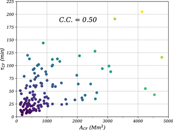
Figure 9. Scatterplot between the area (ACF) and lifetime (τCF) of CFs. The correlation coefficient is ∼0.50.
Download figure:
Standard image High-resolution imageAccording to the lifetime, we divide the 134 flares into three groups of the same amount, i.e., 0–25, 25–59, and 59–205 minutes. The percentages of M- and X-class CFs in the three groups are 26% (12/46), 20% (9/45), and 63% (27/43) (see Figure 4(b)). Hence, flares with larger magnitudes tend to have longer lifetimes. In the statistical investigation of CFs (Song & Tian 2018), the end time corresponds to the time when the flux decreases to a point halfway between the peak flux and the preflare level, leading to an average lifetime of 10–20 minutes, which is systematically shorter than our results. Besides, some of the CFs may experience an EUV late phase after the main flare phase observed in "warm" emission lines (e.g., 335 Å) as a result of additional heating (Sun et al. 2013). The much-extended lifetimes in EUV 335 Å compared with SXR lifetimes are out of the scope of this study.
3.4. Peak SXR Flux in 1–8 Å
For the 134 CFs, the peak SXR flux in 1–8 Å ranges from ∼5.9 × 10⁻⁷ to ∼3.9 × 10⁻⁴ W m−2. Figure 10 shows the distribution of the peak SXR flux. It is clear that the distribution could be nicely fitted with a power-law function (e.g., Dennis 1985; Lu & Hamilton 1991; Crosby et al. 1993; Christe et al. 2008) above ∼2 × 10⁻⁶ W m−2:

where F denotes the peak flux, and α = −1.42 denotes the power-law index. The value of α is close to that of microflares at 3–6 keV and less than that of Lyα flares (Lu et al. 2021).

Figure 10. Distribution of the peak SXR flux in 1–8 Å. The power-law index α is labeled.
Download figure:
Standard image High-resolution image3.5. Relation with Remote Brightenings
As mentioned in Section 1, CFs are usually associated with remote brightenings or remote ribbons (Masson et al. 2009; Xu et al. 2017; Song et al. 2018; Chen et al. 2019). In Figure 1(a3), remote brightenings appear to the southwest of the C4.2-class flare, which is overlaid with a cyan line. The brightening has a total length (LRB) of ∼262 Mm and an average distance (DRB) of ∼171 Mm away from the flare center.
For the 134 CFs in this study, we searched for remote brightenings observed by AIA mainly in 304 and 1600 Å, finding that ∼57% (76/134) of CFs have associated remote brightenings, which is shown in Figure 11. Specifically, the association rates with B-, C-, M-, and X-class flares are 25%, 49%, 70%, and 88%, respectively (see Figure 12(a) and Table 3). The increasing rate with flare magnitude indicates that larger flares are more likely to produce remote brightenings. The total length of remote brightening or ribbon is denoted with LRB, and the average distance from the flare center is denoted with DRB. Figure 13 shows the distributions of LRB and DRB. It is revealed that LRB lies in the range of 6.2–381.0 Mm, with a mean value of ∼84.1 Mm. DRB lies in the range of 28.6–186.2 Mm, with a mean value of ∼89.1 Mm. Figure 14 shows the scatterplot between LRB and DRB, indicating a good correlation between the two parameters with a correlation coefficient of ∼0.65. In other words, remote brightenings further away from the main CFs are more likely to have longer extensions. A linear fitting (red dashed line) between the two parameters is performed, i.e.,


Figure 11. Proportions of CFs related to remote brightenings, type III radio bursts, jets, minifilament eruptions (FEs), and CMEs.
Download figure:
Standard image High-resolution image
Figure 12. Association rates of CFs with remote brightenings (a), type III radio bursts (b), jets (c), minifilament eruptions (d), and CMEs (e) for B-, C-, M-, and X-class flares, respectively.
Download figure:
Standard image High-resolution image
Figure 13. Distributions of the total length (LRB) and average distance (DRB) of remote brightenings associated with CFs.
Download figure:
Standard image High-resolution image
Figure 14. Scatterplot between the total length (LRB) and average distance (DRB) of remote brightenings. The result of linear fitting is plotted with a red dashed line. The correlation coefficient (∼0.65) is labeled.
Download figure:
Standard image High-resolution imageTable 3. Numbers of CFs Associated with RBs, Type III Radio Bursts, Jets, Minifilament Eruptions, and CMEs
| Activity | B-class | C-class | M-class | X-class | Total |
|---|---|---|---|---|---|
| CF | 4 | 82 | 40 | 8 | 134 |
| RB | 1 | 40 | 28 | 7 | 76 |
| type III | 0 | 36 | 24 | 3 | 63 |
| jet | 1 | 43 | 21 | 4 | 69 |
| FE | 1 | 25 | 18 | 7 | 51 |
| CME | 0 | 17 | 14 | 6 | 37 |
Download table as: ASCIITypeset image
To investigate the relationship between flare magnitude and association with remote brightenings, we divide LRB and DRB into three groups with the same numbers. The values of LRB are divided into 0–29, 29–80, and 80–381 Mm. The values of DRB are divided into 0–72, 72–93, and 93–186 Mm. The percentages of M- and X-class CFs in each group are plotted in Figures 4(c)–(d). The percentages increase systematically with both parameters, indicating that flares with larger magnitudes are more likely to produce longer remote brightenings or ribbons. In the 3D numerical simulations of jets confined by large-scale coronal loops (Wyper & DeVore 2016; Wyper et al. 2016), the aspect ratio of the fan-spine structure is between 1.0 and 2.7. In our study, the aspect ratio is defined as  , which has a range of 0.8–6.7 and a mean value of ∼2.9. Hence, the results will impose constraints on numerical simulations of CFs in the future (Pontin et al. 2013).
3.6. Relation with Type III Radio Bursts
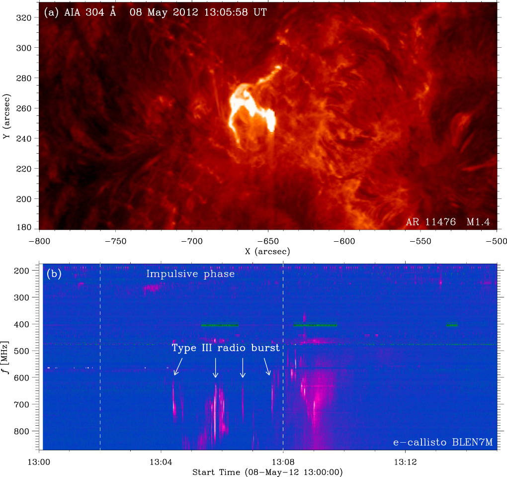
Flare-accelerated nonthermal electrons propagating along open field lines are capable of producing type III radio bursts (Benz et al. 2005; Morosan et al. 2014; Reid & Ratcliffe 2014; Zhang et al. 2015). In Figure 15, the top panel shows the 304 Å image of an M1.4-class CF in AR 11476 on 2012 May 8. The corresponding radio dynamic spectra recorded by the e-Callisto/BLEN7M station is displayed in the bottom panel. It is obvious that type III radio bursts around 700 MHz with fast frequency drift occur during the impulsive phase, when the release rate of magnetic free energy is maximum. The existence of radio bursts is confirmed by the WIND/WAVES observation.

Figure 15. (a) AIA 304 Å image of the M1.4-class CF occurring in AR 11476 on 2012 May 8. (b) Radio dynamic spectra of the flare recorded by the e-Callisto/BLEN7M station. The arrows point to the type III radio bursts. The white dashed lines mark the start and peak times of the flare.
Download figure:
Standard image High-resolution imageFor the 134 CFs, 47% (63/134) of them are accompanied with type III bursts during the impulsive phases, which is displayed in Figure 11. Note that those occurring in the preflare or decay phases are considered as unrelated events, which may result in an underestimate of the total amount. In Figure 12(b), the proportions of CFs related to type III bursts at various flare magnitudes are demonstrated, being 0%, 44%, 60%, and 38% for B-, C-, M-, and X-class CFs, respectively. The relatively lower proportion in B-class flares may be due to the limited number of samples. Hence, there is no correlation between the flare magnitude and type III bursts. In other words, the production of type III bursts depends mainly on the magnetic topology instead of flare energy (Krucker et al. 2011; Glesener et al. 2012; Duan et al. 2022).
3.7. Relation with Coronal Jets
As mentioned in Section 1, CFs are frequently associated with hot coronal jets observed in EUV wavelengths (Li & Yang 2019; Zhang & Ni 2019; Zhang 2020; Zhang et al. 2021) or cool surges observed in Hα (Wang & Liu 2012; Xu et al. 2017). In Figure 1, the C4.2-class flare is accompanied by a blowout jet (Zhang et al. 2016a; Dai et al. 2021). For the 134 events, about half of them are accompanied by jets in 304 Å, which is displayed in Figure 11. In Figure 12(c), the proportions of CFs related to jets at various flare magnitudes are demonstrated, being 25%, 52%, 53%, and 50% for B-, C-, M-, and X-class flares, respectively. Therefore, there is no preference of jet production for CFs with larger magnitudes as well (Chae et al. 1999; Shibata et al. 2007; Duan et al. 2022).
3.8. Relation with Minifilament Eruptions
The occurrence of CFs is often associated with filament or minifilament eruptions (Wang & Liu 2012; Jiang et al. 2013; Sun et al. 2013; Yang & Zhang 2018). In this scenario, breakout-type magnetic reconnection takes place near the null point after the filament embedded in the fan dome rises up (Joshi et al. 2015; Wyper et al. 2017). The initiation of filament eruption may result from magnetic flux emergence (Li et al. 2017), rotation (Xu et al. 2017), or ideal MHD instabilities. The null-point reconnection not only accelerates nonthermal electrons to produce the circular ribbon in the chromosphere, but speeds up the filament eruption as well (Zhang et al. 2021).
Most of the homologous CFs in AR 12434 are triggered by minifilament eruptions (Zhang et al. 2016a, 2021). Figure 1(a2) shows the AIA 304 Å image of the C4.2-class flare, and the minifilament within the circular ribbon is pointed to by the arrow. For the 134 events, 38% (51/134) of them are associated with filament eruptions, which is displayed in Figure 11. Figure 12(d) shows the proportions of CFs related to minifilament eruptions: 25% (1/4), 30% (25/82), 45% (18/40), and 88% (7/8) for B-, C-, M-, and X-class flares, respectively. The increasing proportions with flare classes indicate that larger flares are more likely to be triggered by filament eruptions.
3.9. Relation with CMEs
As mentioned in the previous section, CFs are sometimes triggered by filament or minifilament eruptions. The eruption may also drive a CME observed in the WL coronagraphs (Joshi et al. 2017; Liu et al. 2020; Kumar et al. 2021). In Figure 16, the left panel shows the 304 Å image of the M7.3-class CF in AR 12036 on 2014 April 18 (Joshi et al. 2015). The associated CME at a speed of ∼1203 km s−1 in the LASCO/C2 FOV is displayed in the right panel. For the 134 CFs, only 28% (37/134) of them are related to CMEs, which is shown in Figure 11. It is evident that the association rate with CMEs is the lowest while the association rate with remote brightenings is the highest in our investigation. In other words, most of (∼72%) CFs are confined rather than eruptive (Wyper & DeVore 2016; Li et al. 2018; Yang & Zhang 2018). The CME association rates for B-, C-, M-, and X-class flares are 0%, 21%, 35%, and 75%, which is displayed in Figure 12(e). The increasing CME rates with flare magnitudes are consistent with previous findings, suggesting that larger flares are more likely to produce CMEs (Yashiro et al. 2005, 2006). The low percentage of CMEs is expected, since magnetic flux ropes are required to generate CMEs in most cases (Vourlidas et al. 2013). For eruptive flares, two parallel ribbons or S-shaped ribbons appear on both sides of the polarity inversion lines (Aulanier et al. 2012; Janvier et al. 2013; Savcheva et al. 2016). Therefore, the formation of a CF is unlikely in this situation.

Figure 16. (a) AIA 304 Å image of the M7.3-class flare in AR 12036 on 2014 April 18. (b) WL image of the associated CME at a speed of 1203 km s−1 in the LASCO/C2 FOV.
Download figure:
Standard image High-resolution imageThe distribution of the linear speed (VCME) of the 37 CMEs is drawn in Figure 17. The values of VCME lie in the range of 120–1203 km s−1, with an average speed of ∼517 km s−1, which is slightly higher than that of CMEs near solar maximum (Yashiro et al. 2004). Figure 18 shows the scatterplot between the peak flux in 1–8 Å and VCME of the 37 eruptive flares. A positive correlation is clearly demonstrated with a correlation coefficient of ∼0.37, which is consistent with the previous finding that CMEs associated with X-class flares are remarkably faster than those associated with C-class flares (Yashiro et al. 2005).

Figure 17. Distribution of the CME speed (VCME) related to CFs.
Download figure:
Standard image High-resolution image
Figure 18. Scatterplot between the peak SXR flux in 1–8 Å of CFs related to CMEs and VCME. The correlation coefficient is ∼0.37.
Download figure:
Standard image High-resolution imageOut of the 37 CMEs, 30 of them are normal or partial halo CMEs, and 7 of them are full halo CMEs. Some of them are jet-like, narrow CMEs with an angular width (WCME) less than 25°. Figures 19 and 20 show scatterplots between WCME and the peak flux of flares and VCME, respectively. It is clear that WCME have positive correlations with flare peak flux and VCME. Note that full halo CMEs (WCME = 360°) are not included when calculating the correlation coefficients. The result in Figure 20 suggests that faster CMEs tend to be wider, which is in line with previous statistical investigation (Yashiro et al. 2004).

Figure 19. Scatterplot between the peak SXR flux in 1–8 Å of CFs related to CMEs and the CME angular widths (WCME). The correlation coefficient is ∼0.54.
Download figure:
Standard image High-resolution image
Figure 20. Scatterplot between VCME and WCME, indicating faster CMEs tend to be wider. The correlation coefficient is ∼0.56.
Download figure:
Standard image High-resolution imageAccording to their speeds, the 37 CMEs are divided into three groups with roughly the same numbers. Figure 21(a) shows that the percentages of M- and X-class CFs are 33% (4/12), 42% (5/12), and 85% (11/13) for 0–360, 360–583, and 583–1203 km s−1, respectively. The association rates of CMEs with big flares increase with the CME speeds, which is consistent with the fact that faster CMEs are more related to flares with larger magnitudes (Yashiro et al. 2005, 2006). Figure 21(b) shows the percentages of filament eruptions for the three groups of CMEs, being 50% (6/12), 58% (7/12), and 54% (7/13). The association rates of CMEs with filament eruptions are independent of the CME speeds.

Figure 21. (a) Percentages of M- and X-class flares for the three groups of CMEs. (b) Percentages of minifilament eruptions for the three groups of CMEs.
Download figure:
Standard image High-resolution imageFast CMEs are capable of driving shock waves, which are associated with type II radio bursts (e.g., Ontiveros & Vourlidas 2009; Zucca et al. 2018; Mancuso et al. 2019). For the 37 eruptive CFs accompanied by CMEs, seven are associated with type II bursts, including two X-class (No. 3, 53) and five M-class (No. 34, 49, 77, 82, 83) flares. In Figure 22, the left panels show three CFs observed in 131 Å. The middle panels show the corresponding CMEs observed by LASCO/C2, with the apparent speeds being labeled. The related shock waves with relatively lower intensities are pointed to by the arrows. The right panels show radio dynamic spectra recorded by the e-Callisto stations, where type II radio bursts with drifting frequency are pointed to by the arrows.

Figure 22. Left panels: three CFs observed by AIA in 131 Å. Middle panels: associated CMEs and shock waves observed by LASCO/C2. The apparent speeds of the CMEs are labeled. Right panels: radio dynamic spectra of the three events recorded by the e-Callisto stations, showing the corresponding type II radio bursts with drifting frequency.
Download figure:
Standard image High-resolution image
4. Conclusion and Discussion
In this paper, we conducted a comprehensive statistical analysis of 134 CFs observed by SDO/AIA from 2011 September to 2017 June, including 4 B-class, 82 C-class, 40 M-class, and 8 X-class flares. The physical properties of CFs are derived, including the location, area (ACF), equivalent radius (rCF) assuming a semispherical fan dome, lifetime (τCF), and peak SXR flux in 1–8 Å. Combining with the observations from the SOHO/LASCO, WIND/WAVES, and radio stations of the e-Callisto network, we also explored the relations with remote brightenings, type III radio bursts, coronal jets, minifilament eruptions, and CMEs. The main results are as follows:
- 1.All CFs are located in ARs, with the latitudes between −30° and 30°. Most of the areas are ≤5000 Mm2, with a mean value of ∼1215 Mm2. The distribution could be fitted with a lognormal function, where μ = 6.51 and σ = 0.66. The equivalent radii, representing the heights of magnetic null points, are between 6 and 87 Mm, with a mean value of ∼16.8 Mm.
- 2.The lifetimes are between 4 and 205 minutes with a mean value of ∼50 minutes. The distribution could also be fitted with a lognormal function, where μ = 3.6 and σ = 0.64. There is a positive correlation between the lifetime and area, indicating that CFs with larger sizes tend to have longer lifetimes. The peak SXR flux in 1–8 Å is well in accord with a power-law distribution with an index of −1.42.
- 3.For the 134 CFs, 57% of them are accompanied by remote brightenings or ribbons. The association rates with RBs increase with flare magnitudes. The mean values of total length (LRB) and average distance (DRB) of remote brightenings are ∼84 and ∼89 Mm, respectively. A positive correlation exists between the two parameters, i.e., DRB = 67.56 + 0.26LRB.
- 4.About 47% and 51% of the 134 CFs are related to type III radio bursts and jets, respectively. The association rates are independent of flare classes, meaning that the production rates of type III radio bursts and jets depend mainly on the magnetic configuration instead of the flare energy. About 38% of CFs are related to minifilament eruptions, and the association rates increase with flare classes.
- 5.Only 28% of CFs are related to CMEs, meaning that a majority of them are confined rather than eruptive events. This is in agreement with the relatively high association with remote brightenings considering the particular magnetic topology of CFs. The association rates with CMEs increase with flare magnitudes. The apparent speeds of CMEs are between 120 and 1203 km s−1, with a mean value of ∼517 km s−1. There is a positive correlation between the CME speed and peak SXR flux in 1–8 Å. The angular widths of CMEs (WCME) are between 13° and 360°. A linear correlation exists between the angular width and apparent speed, indicating that faster CMEs tend to be wider.
Li et al. (2021) analyzed 719 flares during 2010–2019, finding that the total unsigned magnetic flux (ΦAR) plays a decisive role in determining the eruptive character of a flare. For the 134 CFs, only 37 events are eruptive. The mean and median values of the total area for the eruptive CFs are significantly greater than confined CFs. Hence, it is worthwhile investigating the total magnetic fluxes of CFs and justifying the conclusion of Li et al. (2021).
Of course, the current statistical work has limitations. First, the sample is not large enough, leading to uncertainties in the results. Those flares with irregular or complex ribbons are excluded to minimize the ambiguity. The 134 flares were observed by SDO/AIA from 2011 September to 2017 June, including four B-class and eight X-class flares. The numbers of CFs will certainly grow after extending the dates to 2021 June, for instance. Second, the shapes of outer ribbons are fitted with circles or ellipses, which is suitable in most cases. However, the fitting is unsatisfactory for irregular ribbons (Joshi et al. 2015). The method in Song & Tian (2018) seems to be more appropriate. Besides, the assumption of semispherical fan surface is not always valid to estimate the heights of null points (Vemareddy & Wiegelmann 2014). Third, the values of apparent speeds and angular widths of CMEs suffer from projection effects from a single viewpoint. 3D reconstruction of the shapes of CMEs is helpful to minimize this effect (Zhang 2022). Finally, the properties of CFs are still incomplete. The distribution of thermal energy and association rate with QPPs will be the focus of our next paper. The results are important to get a better understanding of solar flares and provide valuable constraints on 3D MHD simulations. In the future, new insights into CFs and the related activities will be obtained from observations of the Spectrometer/Telescope for Imaging X-rays (Krucker et al. 2020) on board Solar Orbiter (Müller et al. 2020).
The authors appreciate the referee for valuable suggestions and comments. The e-Callisto data are courtesy of the Institute for Data Science FHNW Brugg/Windisch, Switzerland. SDO is a mission of NASA's Living With a Star program. The AIA and HMI data are courtesy of the NASA/SDO science teams. This work is supported by NSFC grants (No. 11790302, 11790300), and the Strategic Priority Research Program on Space Science, CAS (XDA15052200, XDA15320301).
Footnotes
- 4
- 5
- 6
- 7
- 8