

Abstract
A novel colossal polarization architecture generated at the fast Li-ion conductor–dielectric interface is proposed. A fast Li-ion conductor, La0.57Li0.29TiO3 (LLT), is utilized as the conductive core material, while the ferroelectric barium titanate (BaTiO3; BT) was coated onto the LLT as the shell layer via a liquid phase reaction. After densification of the composites, the shell BT fully transforms into the interdiffusion layer, i.e. (Ba, Li, La)TiO3 (BLLT). The BLLT effectively hinders Li diffusion, leading to a colossal polarization at the core–shell interface. Consequently, the optimized BT–LLT achieves dielectric characteristics at 1 kHz with permittivity of 3.28 × 10⁴.
Export citation and abstract BibTeX RIS
Recently, dielectric devices represented by multilayered ceramic capacitors (MLCCs) have been greatly miniaturized while retaining high volumetric capacitance density. The downsizing of dielectric grains into submicron or tens-of-nanometers size achieves a drastic reduction in the dielectric layer thickness, allowing higher volumetric capacitance density. 1–3) In fact, the volumetric capacitance efficiency of commercial MLCCs now exceeds 100 μF mm–3. 4–6) Barium titanate (BaTiO3; BT)-based perovskite ferroelectrics, exhibiting a high permittivity (ε' ∼ 104) originating from ferroelectric domain vibrations and polar nanoregions as well as soft phonon modes, 7–14) have been benchmarked as dielectric layers in capacitors for decades. The dielectric constant of BT, however, notably decreases when the grain size falls below ∼1 μm. 15–19) This drawback is well-recognized as the "size effect", which is an unavoidable phenomenon attributed to the weakening of tetragonality that leads to the depression of domain motions and soft phonons. 20) To accommodate the demand for next-generation capacitors, a new breakthrough delivering ultrahigh polarizability architecture regardless of dielectrics size is necessary.
One prospective approach to induce colossal polarization is the introduction of a barrier layer (BL) into the interface between the semiconductor core and dielectric insulator shell. 21–23) In this BL configuration, electron transport within the semiconductor intragrains, which enables long-distance charge migration over distances ranging from tens of nanometers to a few microns (depending on the core grain size), leads to colossal polarization. The polarization, which originates from charge transport within the intragrains, is larger, by a few digits, than the conventional polarization modes of ferroelectrics. This is because charge displacements in the ionic fluctuations of phonons, and in the domain wall motions, are limited to the range of picometers to a few nanometers. In fact, semiconducting polycrystalline CaCu3Ti4O12 has an extremely large permittivity (εr) of ∼105 due to the BL induced at the grain boundaries. 24–27) In conventional BL capacitors electrons jump across the insulating layer into external electrodes, leading to an extremely large dielectric loss, e.g. the tanδ (ε''/ε') exceeds 100% via electron exchange at the bulk–electrode interface. Replacement of semiconductors with a fast ionic conductor would effectively suppress the dielectric loss while maintaining very high polarizability, since ions are trapped at the electrode interface, thereby suppressing electron penetration into the external circuit. Herein, we propose a novel composite architecture consisting of a fast Li-ion conductor decorated with a dielectric layer [Fig. 1(a)], which promises colossal polarizability with efficient reduction of dielectric loss.
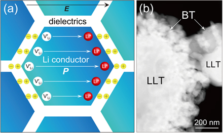
Fig. 1. (Color online) (a) Schematic of colossal polarization architecture originating from a fast Li-ion conductor and a dielectric interface, and (b) STEM image of the LLT powder loaded with 10 mol% of BT.
Download figure:
Standard image High-resolution imageA fast Li-ion conductor, La0.57Li0.29TiO3 (LLT), possessing an intragrain Li conductivity (σLi) exceeding 10–3 S cm–1 at room temperature, 28–31) was used as the conductive core material, while the ferroelectric BT was used as the shell layer. Since the incorporation of low-permittivity dielectrics into a shell layer significantly depresses the series capacitance of the core–shell composite, BT is an acceptable shell-layer candidate due to its relatively high permittivity. Metal organic decomposition (MOD) was used to synthesize the BT–LLT composite powder. The MOD solution consisted of metal acid salts, which are chemically stable under ambient conditions. Therefore, the MOD route easily enables homogeneous coating of nanopowders onto oxides in air, which is not possible in conventional liquid-phase reactions that require an inert atmosphere, e.g. the sol–gel route. The BT loading concentration was varied from 3.0 to 20.0 mol% versus core LLT. A commercial BT-MOD solution (Toshima Manufacturing) consisting of the barium octylate and titanium octylate metal precursors was used, along with octylic acid and 1-methoxy-2-propanol solvents. The core powder, LLT (Toho Titanium), was first dispersed in ethanol. Adequate MOD solution was added and the dispersion was then mixed. The mixture was heated at 70 °C to form the composite gel, which was then heated at 650 °C for 20 h to crystallize the BT.
Figure 1(b) presents a scanning transmission electron microscopy image of the synthesized composite powder. The image corresponds to LLT loaded with 10 mol% of BT. The BT nanoparticles with the thickness (td) of ∼200 nm were homogeneously decorated onto the LLT. The obtained core–shell powders were uniaxially pressed, and then cold isostatically pressed at 125 MPa. The green bodies were subsequently sintered at 1250 °C for 8 h to reach maximum density; all specimens had a relative density exceeding 95%. Powder X-ray diffraction (XRD; Cu-Kα radiation) of specimens annealed at 650 °C revealed that the crystalline BT–LLT was phase-separated. Figure 2 displays the XRD patterns of the densified composites with various BT loadings after heat treatment at 1250 °C. For all of the BT loadings, the BT fully transformed to a new phase, which was assigned to the perovskite (Ba, Li, La)TiO3 (BLLT) having orthorhombic Pnam symmetry. The BLLT is considered a byproduct phase resulting from interdiffusion at the BT–LLT interface; some Li and La ions were extracted from the LLT core, resulting in modification of the pristine LLT into a site-deficient form, i.e. La0.57-δ Li0.29-γ TiO3 (LLT').

Fig. 2. (Color online) XRD patterns of the composite ceramics with various BT loadings after heat treatment at 1250 °C.
Download figure:
Standard image High-resolution imageFigure 3(a) schematically illustrates the modified composite configuration consisting of the LLT' core and BLLT interdiffusion shell layer. The equivalent circuit of the modified composite configuration used to calculate the frequency dependence of the complex permittivity is displayed in Fig. 3(b). The equivalent series circuit has interfacial and intragrain bulk contributions. The Li ions blocked at the interface between the bulk specimen and external electrode generate interfacial polarization (denoted as bulk–electrode in the equivalent circuit), while the Li-ion conductor–dielectric interface also induces colossal polarization (denoted as Li-ion conductor–dielectrics). The intragrain contributions are calculated by taking the two bulk contributions into account, i.e. those of the dielectric and Li-ion conductor. The universal dielectric response (UDR) is commonly used to describe intragrain ion-hopping characteristics. 32–34) In the UDR, the effective conductivity is expressed as σ'(ω) = σdc + σ0 ωs, where σdc corresponds to the intragrain Li conductivity with ω extrapolated to zero (dc). The complex permittivity of a Li-ion conductor was converted from the conductivity term, σ* = σ'(ω) + jσ''(ω), using the UDR.

Fig. 3. (Color online) (a) Schematic of the modified composite configuration consisting of the LLT' core and BLLT interdiffusion shell layer, and (b) the equivalent circuit of the modified composite configuration.
Download figure:
Standard image High-resolution imageFigure 4 displays the frequency dependence of the complex permittivities of the composite ceramics from 40 Hz to 10 MHz at room temperature. The measured dielectric data, and those calculated from the equivalent circuit, are in good agreement. Notably, the bare LLT exhibits colossal polarization at the lowest frequencies (∼102 Hz), where the permittivity ε' exceeds 3.0 × 10⁵. The dielectric loss term, ε'', is extremely large, however, and ε'' exceeds 105 over the same frequency region. This very leaky polarization is attributed to Li migration to the electrode interface via LLT grain boundaries. Another polarization relaxation accompanying a large ε'' peak between 104 and 105 Hz (10–100 kHz) is associated with Li localization at grain boundaries. As for the BT-modified specimens, polarizations at the bulk–electrode interface were hardly observed at the measurement frequencies. The phenomenon is attributed to slow Li diffusion, in turn due to the dielectric BL, BLLT, leading to lower polarization relaxation frequencies. Consequently, dielectric loss (ε'') at the lowest frequencies was significantly suppressed. Colossal polarization at the core–shell (BLLT–LLT') interface was confirmed, while relaxation was observed at 104–105 Hz. This frequency range is similar to that of the grain boundary contribution of bare LLT. The relaxation frequency of the core–shell interfacial polarization is determined by the Li migration time at the core intra-grain. Shortening of the carrier migration time will effectively increase the relaxation frequency. For instance, the downsizing the grain size of the core Li conductor from a few microns to tens of nm allows the faster charge transfer at the intra-grain, resulting in the increase of the relaxation frequency by a digit. Further structural optimization will be therefore necessary to utilize the proposed Li conductor–dielectric composites architecture to the practical MLCCs. The permittivity originating at the core–shell interface decreased with increasing BT loading, whereas the ε'' at low to a few kHz was notably decreased by the BT modification. The dielectric loss reduction is mainly responsible for the elimination of leaky polarization at the electrode interface and efficient Li blocking at the BLLT–LLT' interface. In fact, tanδ for the 3 mol% BT-loaded LLT was 20.0% at 1 kHz, which is one-quarter of the value for bare LLT (80.2%), while exhibiting sufficient permittivity (ε' = 3.28 × 10⁴) at the same frequency. The fitted ε' of BLLT was 1.19 × 10⁴, while that of pure LLT was 7.54 × 10⁴, i.e. 6.3 times larger. The volumetric effect of loading a low-permittivity component is one reason for the reduction in permittivity of the composite compared with the LLT single phase. In other words, the synthesized capacitance of the equivalent series circuit in Fig. 3(b) decreases with increasing BLLT loading. Another possible reason is the reduction in core LLT permittivity with increasing BT due to the induction of Li defects. Figure 5 shows Arrhenius plots of the measured Li conductivity (σdc) of the LLT core loaded with various BT amounts in the temperature range of −45 °C to 110 °C. The activation energy of intragrain Li migration (Ea) and frequency factor (A) are provided in the figure. The Ea hardly changed, while A steadily decreased, with increasing BT loading. The reduction in A is associated with the decrease in Li carrier concentration, consistent with the phase transformation from LLT to the Li-deficient LLT' with BT loading. The decrease in the polarizability of the core LLT' with BT loading is thus associated with the reduction in the Li carrier density due to the Li deficiencies. Consequently, the optimized 3 mol% BT–LLT achieved a relatively large dielectric constant ε' of 3.28 × 10⁴ at a low frequency, 1 kHz, while the tan δ (ε''/ε') was 20.0% at the same frequency. The tanδ however exceeds 100% above 10 kHz due to the partial Li exchanges between the Li conductive core and the interdiffusion layer, BLLT. Further reduction in the densification temperature of the shell BT via tuning of the sintering process and loading of the sintering additives will suppress the formation of the interdiffusion layer, yielding to a lower dielectric loss.
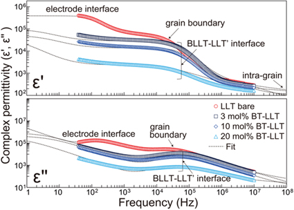
Fig. 4. (Color online) Frequency dependence of the complex permittivities of the composite ceramics from 40 Hz to 10 MHz at room temperature.
Download figure:
Standard image High-resolution image
Fig. 5. (Color online) Arrhenius plots of the measured σdc of the LLT core loaded with various BT loadings. The Ea of intragrain Li migration and frequency factor (A) are also provided in the figure.
Download figure:
Standard image High-resolution image
A novel polarization architecture of a fast Li-ion conductor–dielectric interface delivering colossal permittivity was demonstrated. The BT–LLT composites were synthesized via the MOD route under ambient conditions. Densification of the composites at 1250 °C transformed the shell BT layer into the BLLT interdiffusion phase. The BLLT shell layer effectively hindered Li diffusion, which suppressed leaky polarization at the bulk–electrode interface. In addition, the colossal polarization at the core–shell interface observed in kilohertz regions was attributed to efficient Li blocking at the same interface. The dielectric characteristics achieved herein imply that incorporation of fast Li-ion conductors into dielectric layers dramatically improves the volumetric capacitance efficiency of size-effect-free next-generation capacitors.