
Novel Battery Module Design for Increased Resource Efficiency

 and
and 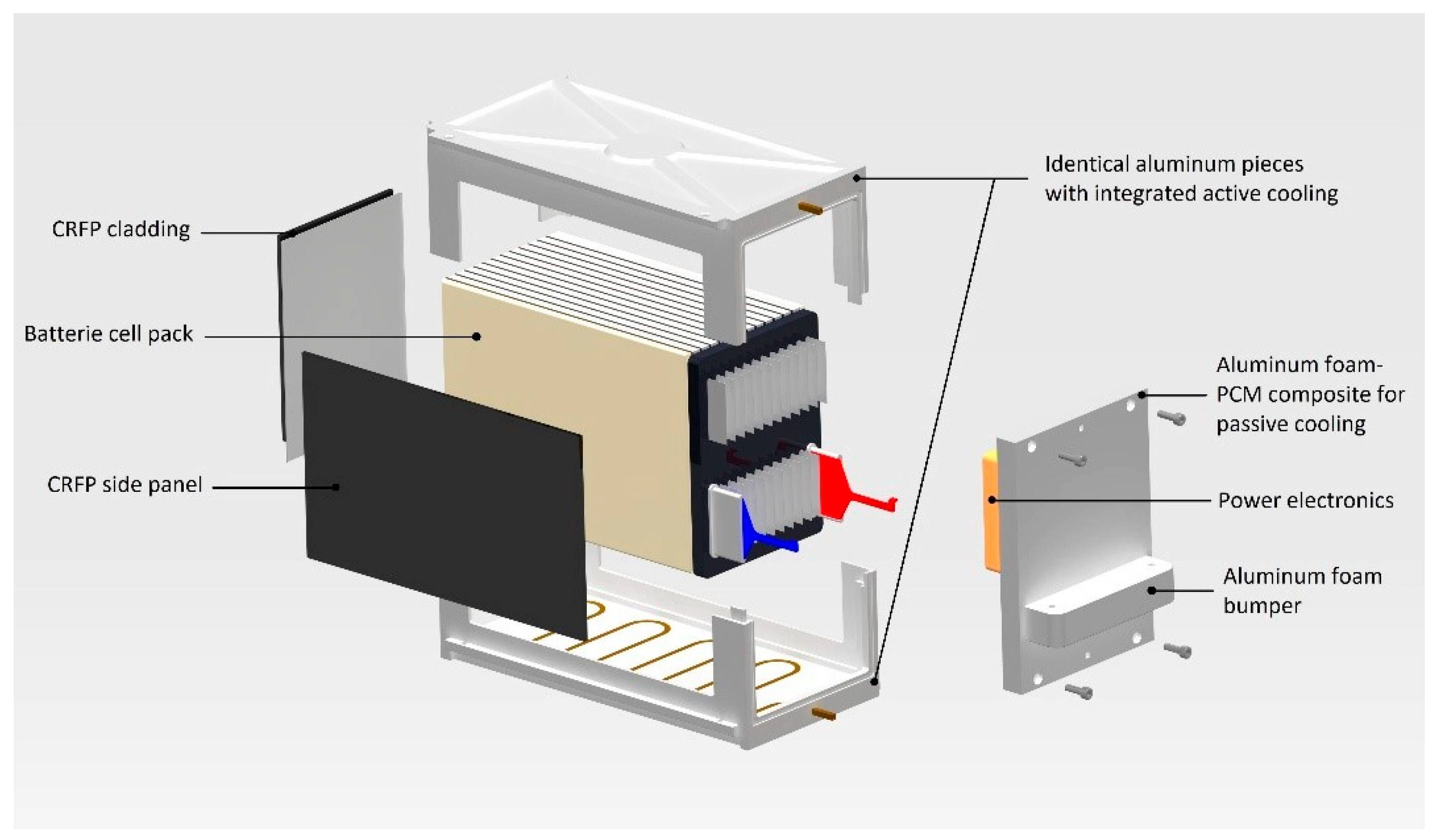
Abstract
:1. Introduction
2. Materials and Methods
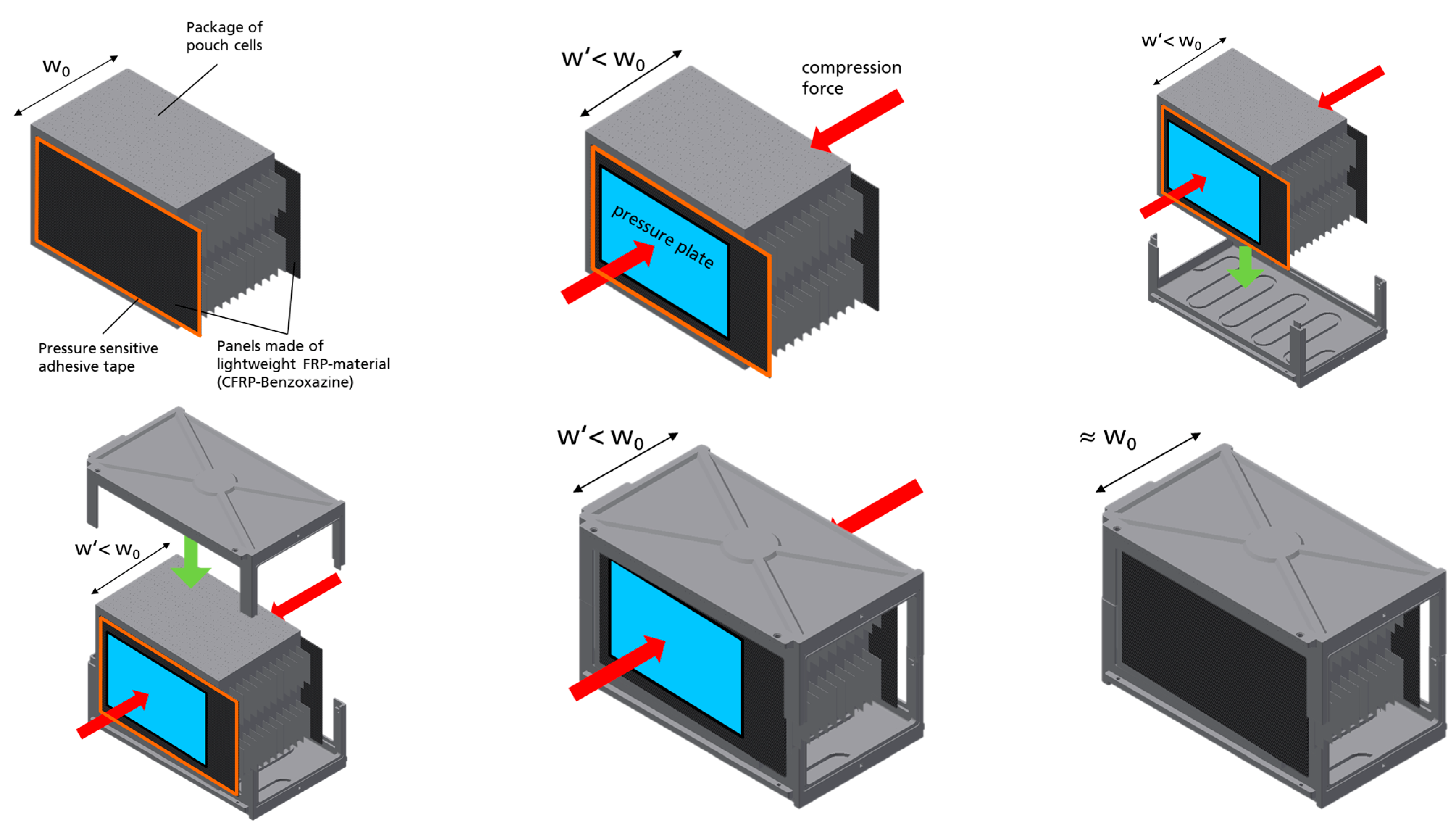
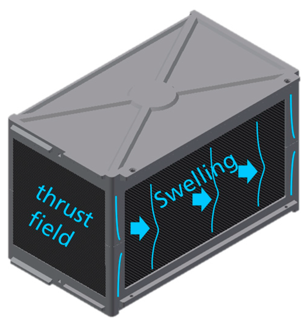
2.1. Structural Design
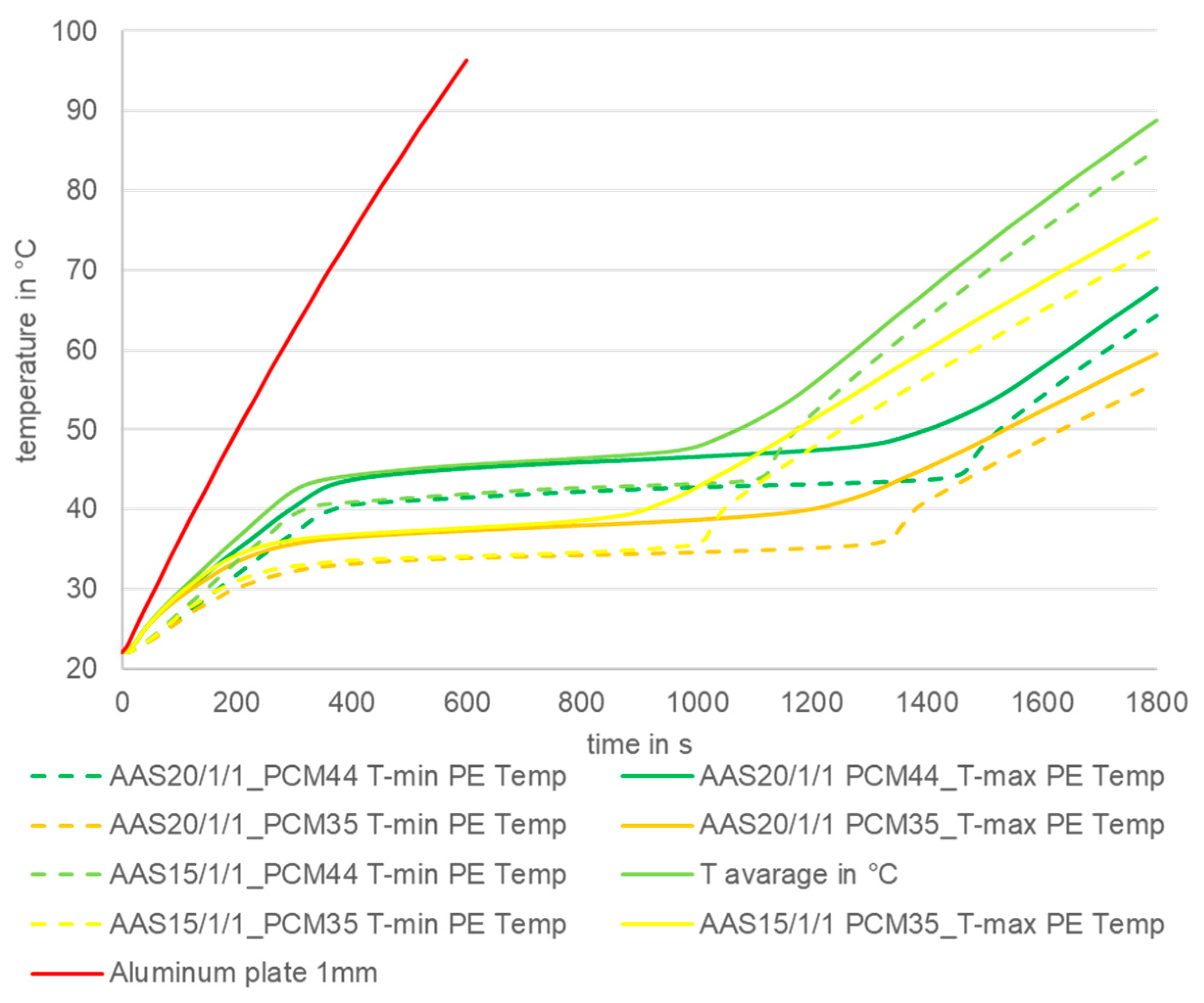
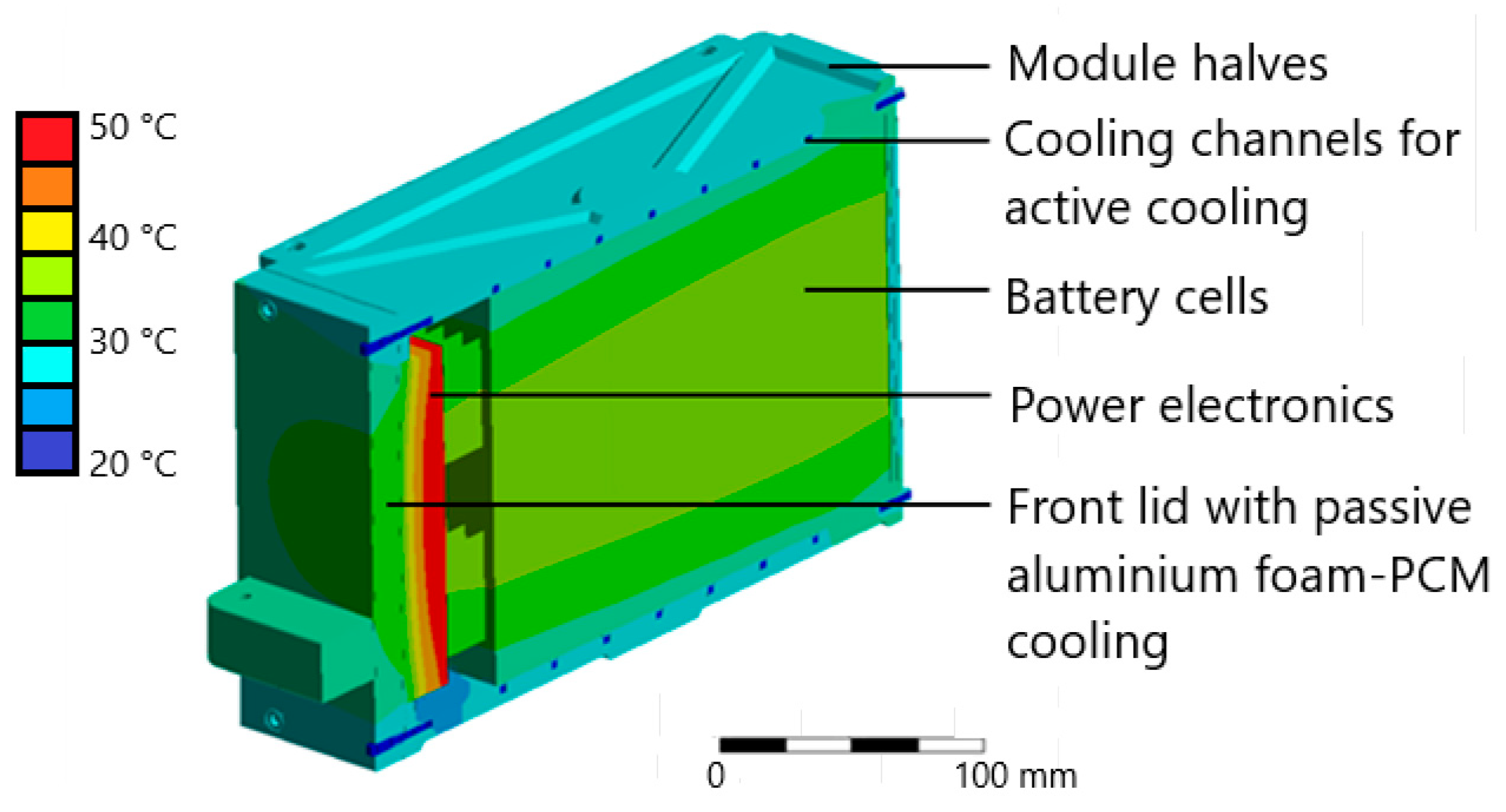
2.2. Thermal Design
3. Results
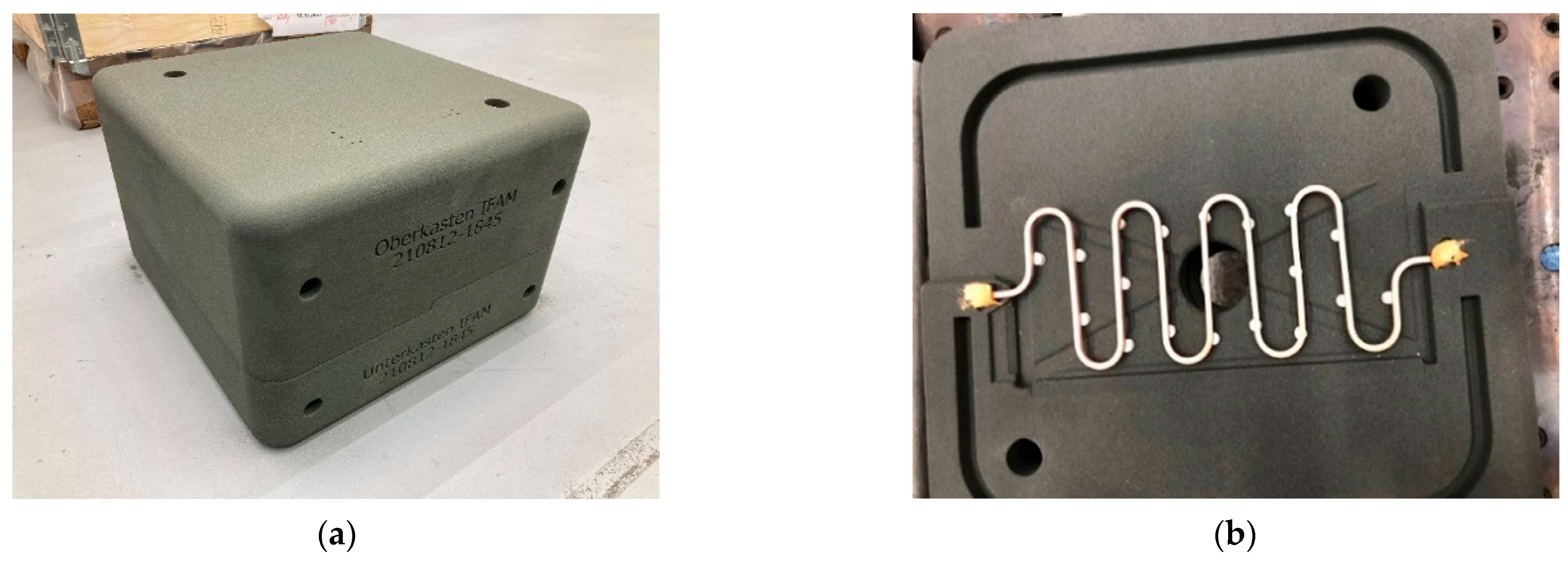
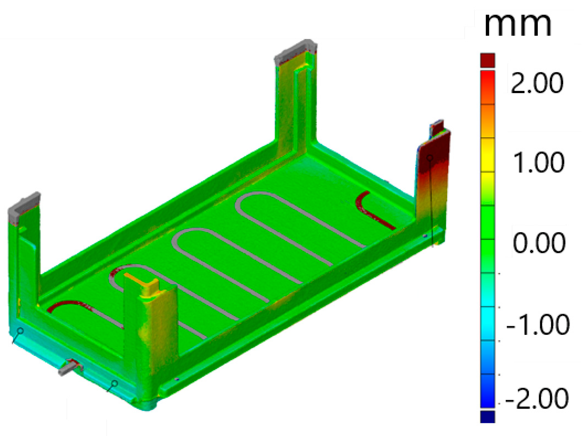
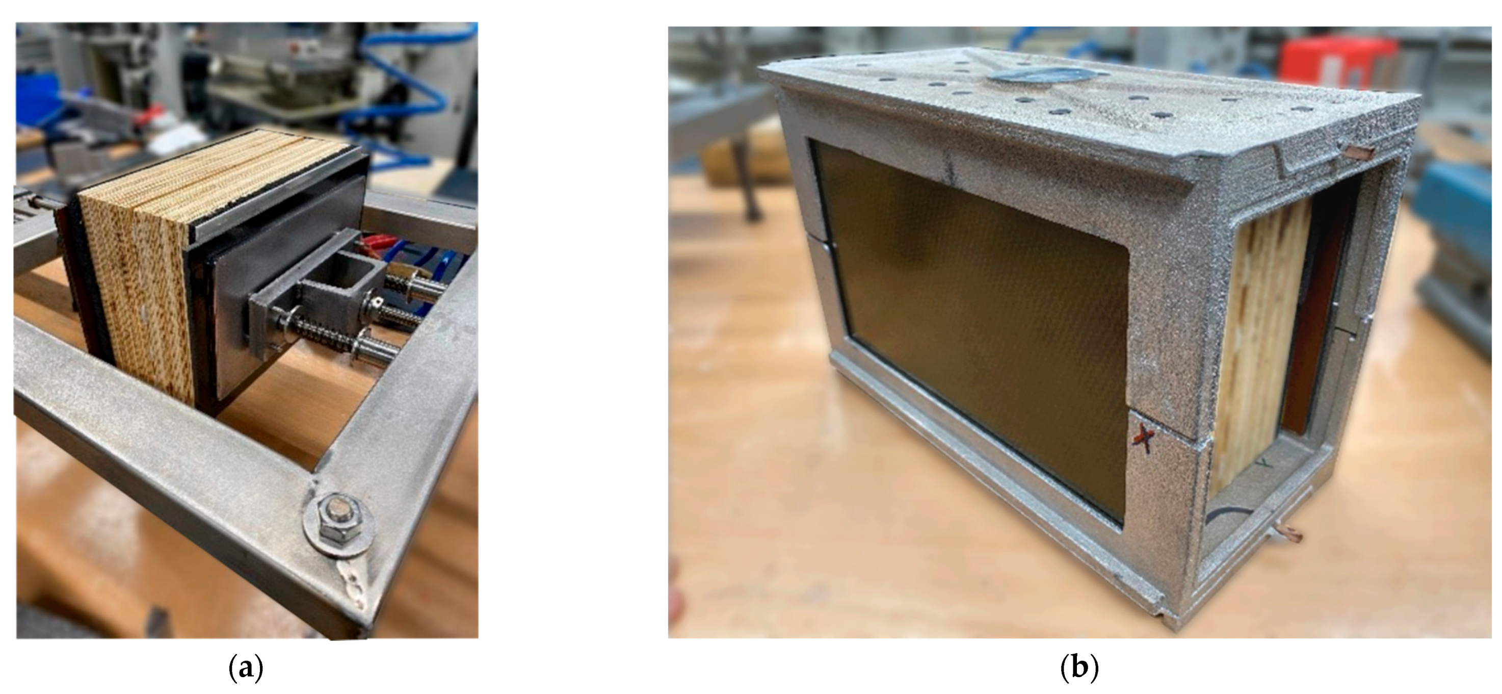
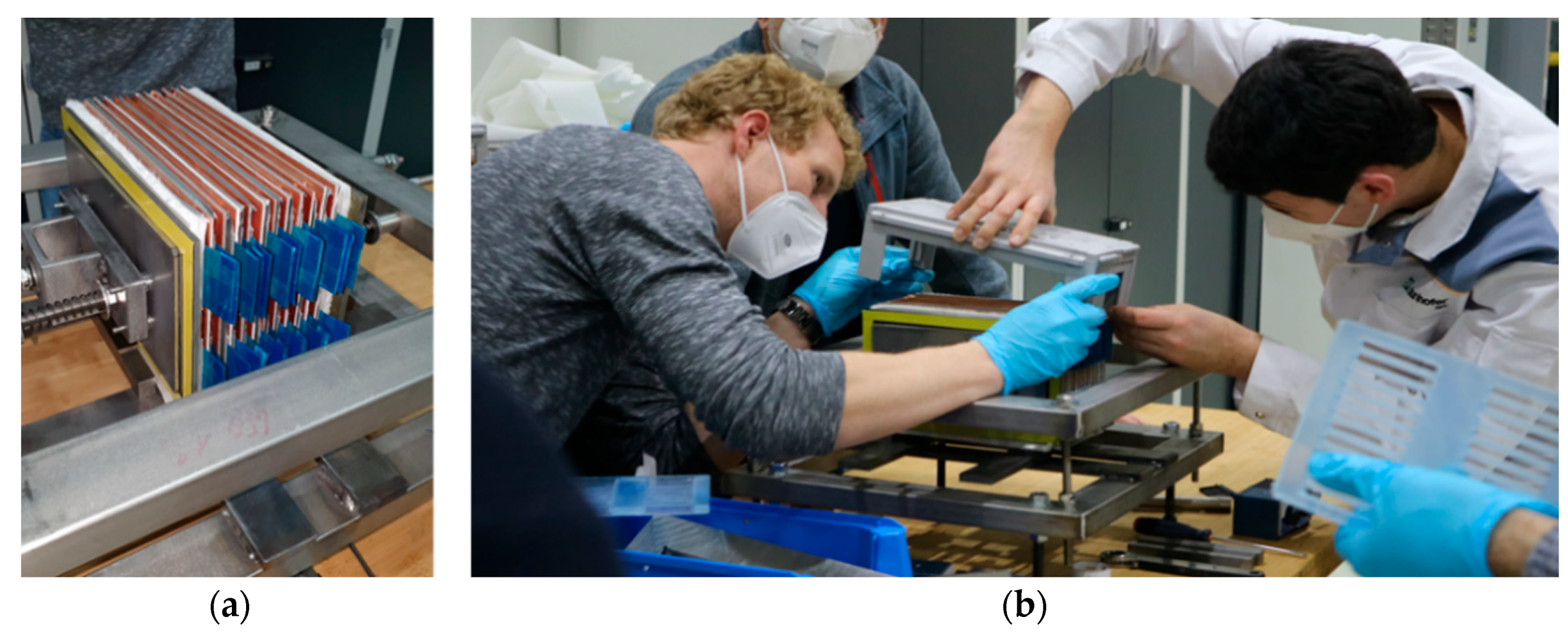
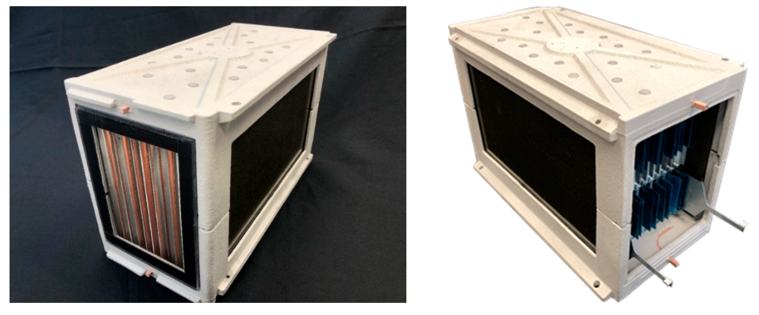
Manufacturing and Joining Technology—Realization of the Demonstrator
4. Discussion
Vision and Further Goals
5. Conclusions
Author Contributions
Funding
Institutional Review Board Statement
Informed Consent Statement
Data Availability Statement
Conflicts of Interest
References
- König, A.; Nicoletti, L.; Schröder, D.; Wolff, S.; Waclaw, A.; Lienkamp, M. An Overview of Parameter and Cost for Battery Electric Vehicles. Electr. Veh. J. 2021, 12, 21. [Google Scholar] [CrossRef]
- McGuckin, N.; Fucci, A. Summary of Travel Trends: 2017 National Household Travel Survey; Daniel, E., Jenkins, P.E., Eds.; Federal Highway Administration: Washington, DC, USA; US Department of Transportation: Washington, DC, USA, 2018; p. 20590. Available online: https://nhts.ornl.gov/assets/2017_nhts_summary_travel_trends.pdf (accessed on 27 April 2022).
- Bastin, Z.; Bhattacharya, S.; Kumar, A. International Electric-Vehicle Consumer Survey, Are Battery Electric Vehicles Here to Stay? Automotive & Industrial. 2019. Available online: https://www.alixpartners.de/media/13453/ap-electric-vehicle-consumer-study-2019.pdf (accessed on 27 April 2022).
- Kostorz, N.; Fraedrich, E.; Kagerbauer, M. Usage and User Characteristics—Insights from MOIA, Europe’s Largest Ridepooling Service. Sustainability 2021, 13, 958. [Google Scholar] [CrossRef]
- Block, L.; Werner, M.; Mikoschek, M.; Stegmüller, S. Developing Technology Strategies for Flexible Automotive Products and Processes. In Advances in Automotive Production Technology—Theory and Application. ARENA2036; Weißgraeber, P., Heieck, F., Ackermann, C., Eds.; Springer: Berlin/Heidelberg, Germany, 2021. [Google Scholar] [CrossRef]
- Füller, K.H.; Schäfer, J.; Zehnpfennig, L.; Budaker, B.; Hossfeld, M.; Keilhoff, D. FlexCar-A Technology Platform Concept for the Future Cyberphysical Vehicle at the Research Campus ARENA2036. In Proceedings of the Werkstoff Plus Auto-9, Tagung für neue Fahrzeug- und Werkstoffkonzepte, Stuttgart, Germany, 20–21 February 2019. [Google Scholar]
- Block, L.; Werner, M.; Spindler, H.; Schneider, B. A variability Model for Individual Life Cycle Paths in Life Cycle Engineering. In Proceedings of the FAPC 2022, Future Automotive Production Conference FAPC 2022, Wolfsburg, Germany, 17–18 May 2022; Dröder, E., Herrmann, C., Vietor, T., Eds.; pp. S1–S10. [Google Scholar]
- Kirchherr, J.; Denise, R.; Hekkert, M. Conceptualizing the circular economy: An analysis of 114 definitions. Recour. Conserv. Recycl. 2017, 127, 221–232. [Google Scholar] [CrossRef]
- Ganesh, S.; Venkatesan, S. Evolution of flexible modular electric vehicle platforms among automotive industry and its influence on battery integration. Int. J. Veh. Struct. Syst. 2021, 13, 361–366. [Google Scholar] [CrossRef]
- Mehling, H.; Cabeza, L.F. Heat and Cold Storage with PCM: An Up to Date Introduction into Basics and Applications; Springer: Berlin/Heidelberg, Germany, 2008. [Google Scholar]
- Schmerler, R.; Hipke, T.; Drebenstredt, C. SMC-Aluminum lightweight battery case design with switchable temperature control functionality. In Proceedings of the Automotive Circle-Conference for Battery Systems in Car Body Engineering, Bad Nauheim, Germany, 26 October 2021. [Google Scholar]
- NIO. Battery Swapping. Available online: https://www.nio.com/blog/current-state-ev-battery-swapping (accessed on 27 April 2022).
- CATL Battery Swap Solution. Available online: https://www.catl.com/en/news/856.html (accessed on 27 April 2022).
- Geely Battery Swapping Tech. Available online: http://zgh.com/media-center/story/8-reasons-why-geelys-battery-swapping-tech-is-the-future-for-evs/?lang=en (accessed on 27 April 2022).


Publisher’s Note: MDPI stays neutral with regard to jurisdictional claims in published maps and institutional affiliations. |
© 2022 by the authors. Licensee MDPI, Basel, Switzerland. This article is an open access article distributed under the terms and conditions of the Creative Commons Attribution (CC BY) license (https://creativecommons.org/licenses/by/4.0/).
Share and Cite
Schmidt, S.; Clausen, J.; van der Auwera, R.; Klapp, O.; Schmerler, R.; Löffler, D.; Werner, M.J.; Block, L. Novel Battery Module Design for Increased Resource Efficiency. World Electr. Veh. J. 2022, 13, 177. https://doi.org/10.3390/wevj13100177
Schmidt S, Clausen J, van der Auwera R, Klapp O, Schmerler R, Löffler D, Werner MJ, Block L. Novel Battery Module Design for Increased Resource Efficiency. World Electric Vehicle Journal. 2022; 13(10):177. https://doi.org/10.3390/wevj13100177
Chicago/Turabian StyleSchmidt, Simon, Jan Clausen, Robin van der Auwera, Oliver Klapp, Rico Schmerler, David Löffler, Maximilian Jakob Werner, and Lukas Block. 2022. "Novel Battery Module Design for Increased Resource Efficiency" World Electric Vehicle Journal 13, no. 10: 177. https://doi.org/10.3390/wevj13100177