Rapidly Pulsed Pumping Accelerates Remediation in A Vertical Circulation Well Model


1
Center for Environmental Research and Education, Duquesne University, Pittsburgh, PA 15282, USA
2
Department of Civil and Environmental Engineering, Pratt School of Engineering, Duke University, Durham, NC 27708, USA
*
Author to whom correspondence should be addressed.
Water 2018, 10(10), 1423; https://doi.org/10.3390/w10101423
Submission received: 18 August 2018
/
Revised: 18 September 2018
/
Accepted: 9 October 2018
/
Published: 11 October 2018
(This article belongs to the Section Hydrology)
Abstract
:One factor that slows groundwater remediation is the sequestration of contaminant in dead-end pores, that is, pores that are not flushed through by flow through the aquifer. Furthermore, rebound of apparently remediated aquifers can occur as a result of the eventual release of the contaminant trapped in these dead-end pores. Since the operational costs generally outweigh the capital costs of a remediation project, reduction of the duration of treatment should reduce the overall cost of the average remediation. It has been shown that a rapidly pulsed flow can increase the mixing between dead-end and well-connected pores through computational fluid dynamics models with idealized pore geometry and column tests. A rapidly pulsed flow induces a deep sweep upon a sudden increase in velocity and a vortex ejection upon a sudden decrease in velocity that substantially accelerates the remediation of contaminant from these dead-end pores. To examine rapidly pulsed pumping in a more realistic configuration, a model vertical circulation well was constructed. The porous medium was well-sorted crushed glass to minimize sorption. Removal of a fluorescent dye, which represents a dissolved contaminant, under a rapidly pulsed flow was compared to a steady flow. The modeled well revealed accelerated removal of dissolved contaminants under a rapidly pulsed flow.
1. Introduction
In pump-and-treat remediation (P&T), contaminated water is pumped from an aquifer, treated, and typically returned to the aquifer via another well. At the start of treatment, the contaminant concentration in the water pumped from the aquifer is typically high and decreases over time. One indication of treatment progress is when the effluent concentration reaches an acceptable level; however, often after treatment is concluded, such as at regulatory checks, the concentration rebounds to an unacceptable level [1,2]. The rebound is due to release of sequestered contaminants. These contaminants are trapped by several mechanisms that fall into three general categories [1]: non-aqueous phase liquids (NAPL) [3,4] and reactions [5], sorption processes [6], and matrix diffusion. The latter is the subject of this work, specifically, contaminant that is trapped in dead-end pores. Dead-end pores are characterized by a recirculation eddy within the pore; there is no flow that sweeps through the individual pore volume. This is in contrast to a well-connected pore that has a flow that sweeps through the pore volume. The recirculation eddy is isolated from the flow through the adjacent well-connected pores by the separatrix: the surface between all of the streamlines within the dead-end and well-connected pore. Under steady flow, contaminant trapped in dead-end pores can only escape by molecular diffusion across the separatrix [7].
Rapidly pulsed pumping has been proposed as a technique that uses the unsteady flow rate within the porous media to break through the separatrix and flush out the majority of the dead-end pore [8]. In rapidly pulsed pumping, the increase in flow causes instability, and the flow in the adjacent well-connected pore flushes into the dead-end pores, which is called a deep sweep. Equally important, the decrease in flow causes instability, and the recirculation eddy within the dead-end pore emerges into the adjacent well-connected pore and brings contaminant away where it is subject to advection from the subsequent increase in flow, which is called a vortex ejection. Rapidly pulsed flow has been tested numerically [8] and with column experiments [9], but there is a need to test it in a more complex porous media and pump configuration.
This work is in the context of P&T because it is the most common remediation technique used alone and in combination with other technologies [10]. Typical remediation work lasts in the order of decades to a century [11,12]. Any advancement to reduce the treatment time will reduce the cost of the typical remediation. The technology introduced here can reduce the treatment time through the enhancement of mixing between dead-end and well-connected pores. In fact, all remediation techniques depend on mixing to completely remediate a site; even in situ solutions such as bioremediation by microorganisms will depend on mixing to deliver remediation agents to dead-end pores.
P&T often uses a series of wells. Some of these wells extract contaminated water and others inject clean or cleaner water. The flow depends on the well configuration. One configuration is the replacement of the separate extraction and injection wells with a vertical circulation well (VCW), which is a well with two screened openings at different depths that are isolated from one another such that one can extract water from the aquifer and the other can inject water to the aquifer. The well can be configured to have extraction from the bottom screen and injection from the top screen (up-flow) or vice versa (down-flow) [13]. A single VCW generates a dipole flow in the aquifer [14]. The configuration of VCWs can be adjusted because of the size and shape of the contaminated aquifer. Multiple VCWs offer added flexibility; for example, a pair of VCWs operated in opposing orientations (one up-flow and another down-flow) will create a circulation system between wells termed a well-to-well conveyor-belt circulating system by Goltz et al. [15]. The VCW, or groundwater circulation wells or simply recirculation wells, was introduced about 25 years ago [16] and continues to be the subject of research.
The VCW allows greater flexibility than conventional P&T configurations. First, once contaminated groundwater is brought to the surface, it is treated as hazardous waste and needs to be hauled away or remediated to rigorous standards before it may be re-injected into the aquifer. The VCW typically has a sufficiently large diameter to allow installation of equipment inside. With technologies placed inside of the VCW, contaminated water can be repeatedly circulated until the required contaminant concentration is achieved; in this manner, remediation does not need to be achieved on the first cycle [17]. Second, the VCW can help maintain water quantity in the parent aquifer as opposed to a transfer of waste to a disposal site. The disposal of the treated groundwater usually through surface discharge is a significant problem with conventional P&T [17]; although, reinjection of the treated groundwater within a VCW may have administrative, public perception, or legal complications. Third, VCWs generate significantly smaller disruptions of groundwater table or piezometric surface than the conventional P&T technologies due to the single well design. Ryan et al. [18] considered conventional and VCW-based P&T designs for remediation of an aquifer under the Massachusetts Military Reservation on Cape Cod. The conventional design would have caused unacceptably large disturbances of the hydraulically connected surface water while the VCW design was more effective and would cause minimal and acceptable disturbances to the surface hydrology. Fourth, the VCW develops vertical hydraulic gradients whereas conventional P&T generally only develops horizontally dominated flow fields. Vertical flows generated by VCWs may flush contaminants stuck in low-conductivity zones in horizontally stratified aquifers [17]. Additionally, in numerical experiments, the radius of the VCW capture zone increased with higher aquifer anisotropy (the ratio of horizontal to vertical conductivity) [16]. The VCW can also be used to take measurements of the aquifer. The dipole-flow test (DFT) is a method to estimate aquifer parameters (horizontal and vertical hydraulic conductivity, and specific storage) from the measurement of the in-well pressure time series in the upper and lower chamber of a single VCW [14,19,20].
VCWs, with the capacity for alternative treatment processes such as in-well air stripping and/or in situ chemical or biological processes, offer an attractive range of alternatives to the conventional P&T technique. Nevertheless, these remediation methods are still limited by diffusion of contaminants from the dead-end pores. None of the existing aquifer remediation approaches optimize the mechanisms of the deep sweep and vortex ejection. Kahler and Kabala [8] demonstrated the application of a rapidly pulsed flow in groundwater remediation to generate these mechanisms to accelerate the removal of contaminant from dead-end pores. The optimal period in the experiments performed by Kahler and Kabala [8,9] was less than one second. The lowest pulse period the authors found was in a bioremediation technique in VCWs of eight hours [21]. The period considered in rapidly pulsed pumping experiments was a factor of approximately 3 × 10⁴ shorter. The mechanisms demonstrated by Kahler and Kabala [8] occur at every pulse; therefore, the increase in pulse frequency also increases the number of mechanisms performed on the pores. Since the VCW induces a flow in the horizontal and vertical directions, it provides an ideal experimental setting to test rapidly pulsed flow for remediation in a laboratory scale.
The experiments described here test two hypotheses, previously suggested by related research. First, a rapidly pulsed flow recovers more contaminant from a VCW tank than steady flow. Second, a rapidly pulsed flow recovers any given quantity of contaminant faster from a VCW tank than steady flow. This hypothesis is a necessary step to field-scale experiments.
2. Materials and Methods
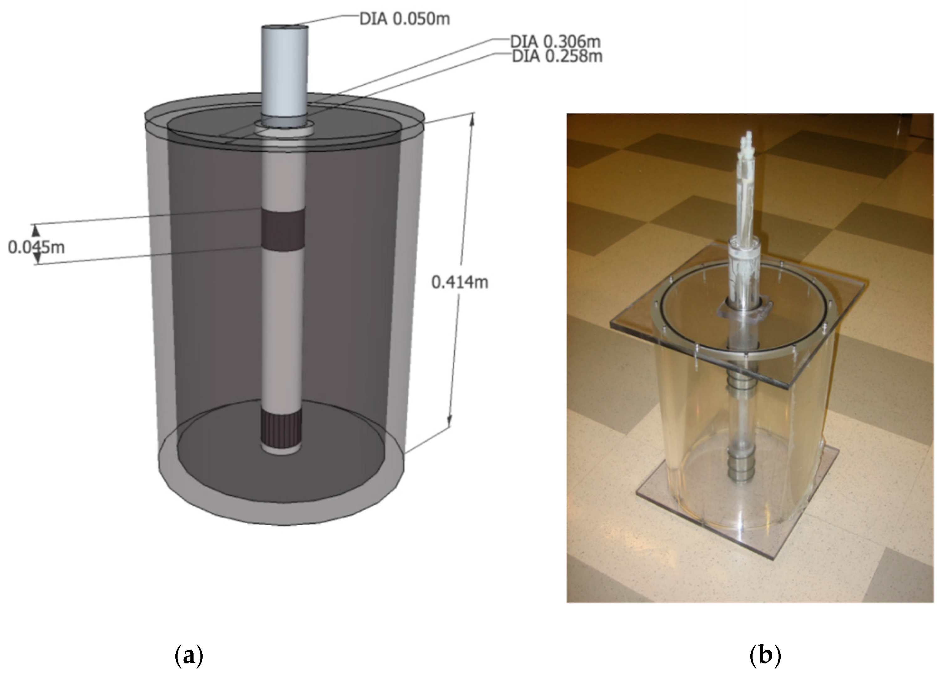
A laboratory-scale VCW was constructed with a cylindrical acrylic chamber with a well in the center (Figure 1). The chamber had an inside diameter of d = 0.258 m and height of h = 0.414 m. It was sealed on the bottom with acrylic cement and machine screws, and on the top with a counter-set gasket and 12 machine screws. The well was constructed of a w = 0.05 m diameter acrylic pipe placed in the center of the chamber and held in place at the bottom and top. The well had two, 4.5 × 10⁻² m high circumferential openings around the cylinder, which were spaced approximately one-quarter and three quarters up the well. The openings were formed by 0.006 m diameter holes placed around the well with minimal separation and covered with #60 brass screen (nominal opening 2.50 × 10⁻⁴ m).
The medium used in the chamber was crushed glass as an idealized solid matrix. Crushed glass was selected to represent an unwashed medium such as a glacial till without organic matter. The glass particles were sieved and passed through a #16 mesh (1.19 × 10⁻³ m) and retained in a #40 mesh (4.20 × 10⁻⁴ m) after 20 min on a standard shaker; the glass had a density of ρ = 221 kg/m3 and a porosity of n = 0.46. Contaminant was modeled with fluorescein dye (Fluorescein Sodium Salt, Sigma-Aldrich, Milwaukee, WI, USA, aqueous solution) and deionized water was used in the solution and as the water supply for the trials. Glass and fluorescein were chosen because fluorescein has low sorption to glass.
Each trial began with a clean, empty chamber and clean, dry crushed glass. The chamber was partially filled with a known concentration of dye (100 μg/L to ensure the outflow would remain well below the top of the linear range of 250 μg/L) and the crushed glass was introduced from the top; this was done to reduce any dead zones or air bubbles in the chamber. The chamber was filled to the top and the lid was placed at an angle to reduce air bubbles before being lowered onto the chamber. The fluorometer (Turner Designs 10AU Field Fluorometer, Sunnyvale, CA, USA) was calibrated with the 100 μg/L fluorescein and the deionized water as the blank prior to each trial.
Three trials for each flow type, steady and pulsed, were conducted. Steady flow was generated from a deionized (DI) water tap and pulsed flow was generated by a peristaltic pump (Manostat® VERA Verisatltic® pump, Barrington, IL, USA). The pulsed flow frequency was approximately 0.5 Hz with a duty cycle of 0.12; this was a limitation of the peristaltic pump. The flow rate was approximately 5 mL/s, which was monitored closely and when variations were detected above 8 mL/s or below 3 mL/s, the flow was adjusted accordingly. Variations were assumed to occur as a result of the DI water supply. The outflow was analyzed by a fluorometer with a time resolution of one-second. The flow rate was computed by manual collection of the outflow in a graduated cylinder over 30 s. The output was numerically integrated to determine the recovery of the dye.
The primary limitation of this analysis is that the VCW tank imposed an artificial boundary condition at the outer-circumference wall. The flow velocity in an unbounded environment was expected to be less than the VCW flow. To determine the range of velocities in the VCW tank and the approximate zone of influence of a VCW in the environment, the flow was simulated in a porous medium with the Brinkman Equations [22,23] in computational fluid dynamics (CFD) software COMSOL Multiphysics, a finite element model, under steady conditions. The numerical domain was constructed to simulate the physical model. The model was constructed as an axisymmetric model to take advantage of the geometry. The numerical mesh was constructed using COMSOL’s built-in “physics-controlled mesh” option. The mesh size was chosen to be the most computationally efficient. That is, a coarser size was preferred under the condition that resultant velocity as a function of radius output was not appreciably different than finer node sizes. The model used the measured porosity and an estimated permeability of k = 10−6 m2. The CFD model was run as steady to determine the average flow velocities with the inflow boundary set at Q = 10−5 m3/s, which corresponds to the approximate average starting flow in the physical VCW tank. The boundary condition was set as a no-slip boundary along all walls except for the inlet and outlet. The tank simulation results were compared to simulations of increasingly larger tanks to represent removal of the artificial boundary of the tank. The domain radius was increased until the flow velocity near the outer boundary became small compared to the flow in the interior of the domain and the velocity in the interior of the domain did not change with further increases in the radius. This domain is referred to as the large-domain VCW.
3. Results
3.1. Vertical Circulation Well Tank
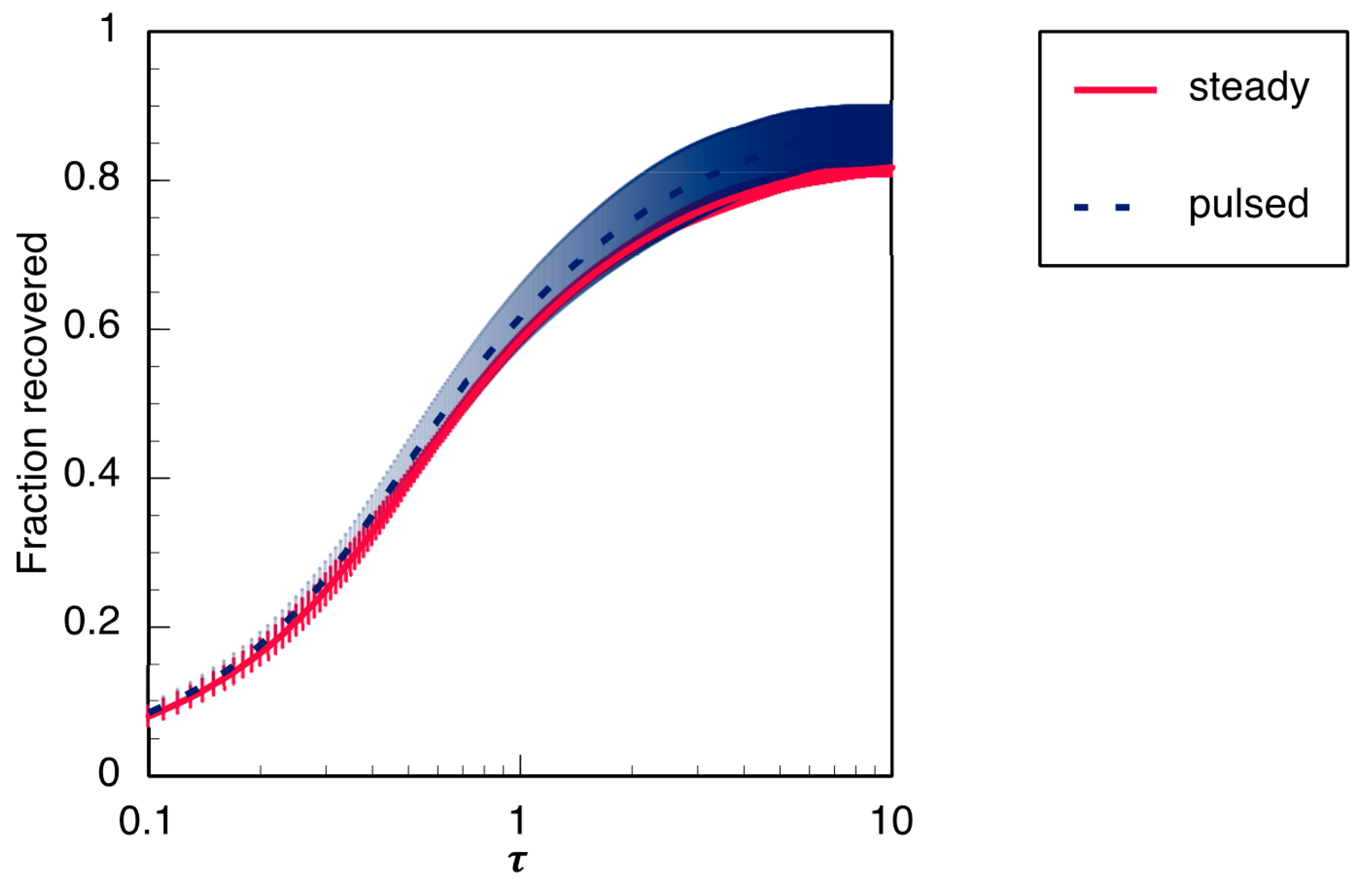
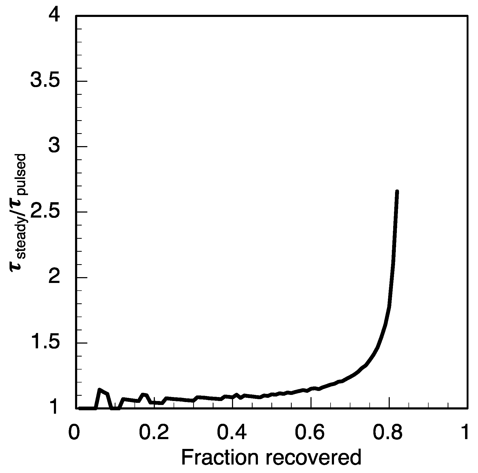
The average recovery from the trials with pulsed flow was higher than the average recovery from the trials with steady flow. Three trials were conducted under each flow type; the average recovery is displayed in Figure 2 with the standard deviation (recovery from each trial is shown in Figure S1). The fraction recovered is the amount of dye recovered normalized by the total amount of dye placed in the tank at the setup of the trial. The recovery is plotted as a function of non-dimensional time, pore volumes, which is the number of pore volumes that have passed through the extraction well at a given time. Pore volumes can be calculated as τ = t Q/Vp, where t is time, Q is volumetric flow rate, and Vp is the pore volume of the chamber. For the practitioner, a better measure of the acceleration of the remediation is the amount of time to achieve a target concentration with rapidly pulsed versus steady flow. To quantify this, the speedup factor is defined at a given fraction recovered, f, as the ratio of the treatment duration needed to achieve the fraction recovery with steady flow over the duration with pulsed flow, SF = τsteady|f/τpulsed|f, and plotted against f in Figure 3. The speedup factor increases with the target recovery, which indicates that more recovery will require proportionately less time under pulsed flow.
3.2. Computational Fluid Dynamics
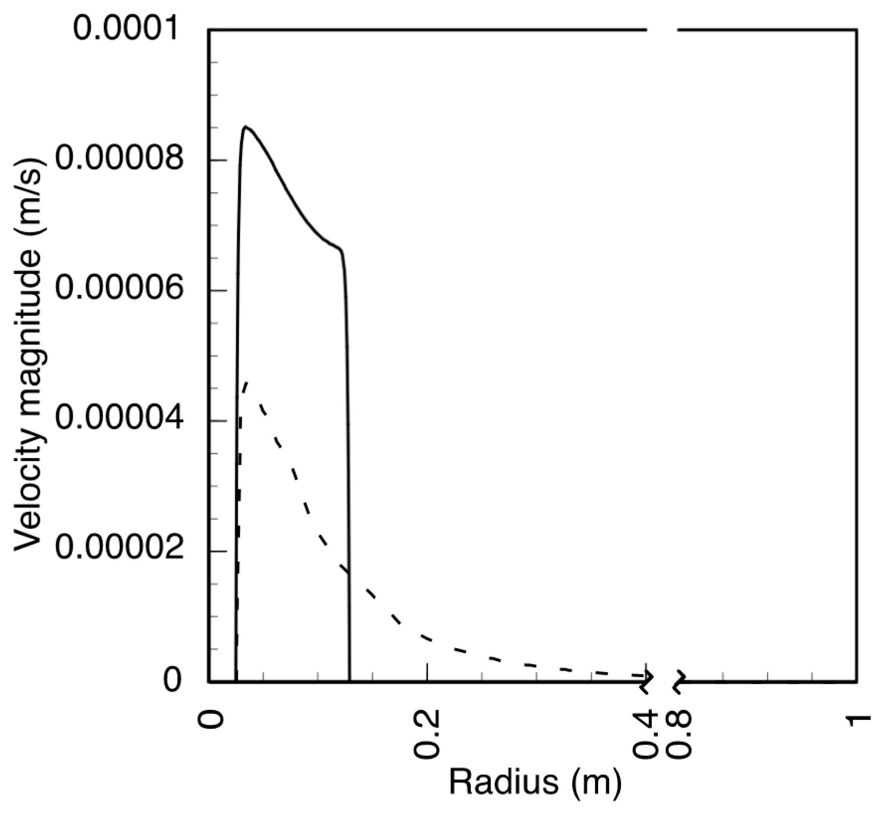
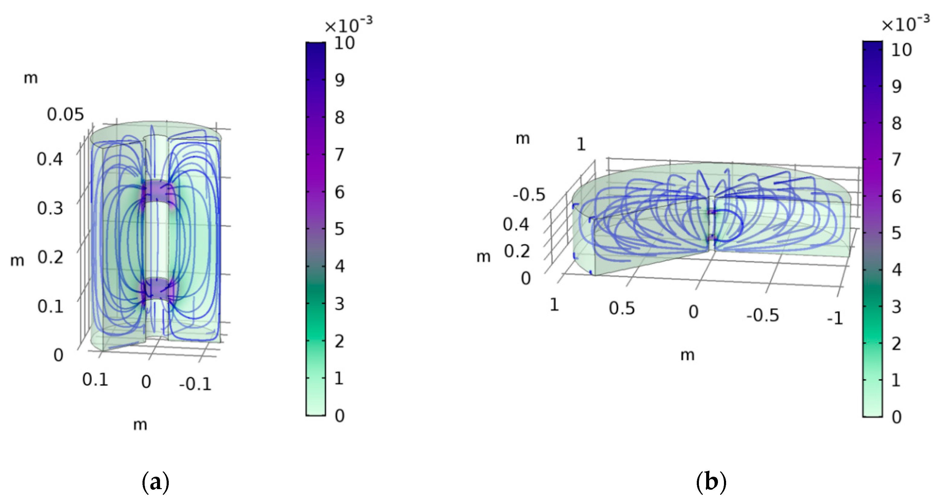
The CFD simulations were run at a “fine” mesh option, which resulted in 4793 nodes in the interior and 279 along the boundary for the VCW domain; while the “normal” mesh reproduced a similar result, there was little difference in computation time. Coarser meshes were not explored as it was not needed for computational efficiency. As stated in the Methods section, the radius of the VCW tank domain was r = 0.129 m. The large-domain VCW, whose outer wall was placed at a radius large enough where it did not significantly change the flow on the interior of the tank, was not found to change the interior flow at r = 1 m. The results showed that the typical fluid velocity magnitude in a less-constrained tank is lower than the fluid velocity in the simulated tank for the same flow rate as predicted. For comparison, the fluid velocity magnitude (u) versus position (r) for both simulations was obtained for a transect along the plane z = 0.207 m; since the model is axisymmetric along the center z-axis, only the positive r-vector is shown in Figure 4. The simulations also show that the fluid follows a roughly dipole path, as previously reported [14]. The velocity surface plot and streamlines show the three-dimensional flow path for both simulations in Figure 5.
4. Discussion
Traditional pump-and-treat remediation uses steady flow or flow rates changed on the time scale of months. This generates a steady flow within dead-end pores that is separate from the mean flow through the aquifer. Rapidly pulsed flow interrupts those steady, separated eddies within the dead-end pore to enhance mixing and remove sequestered contaminant. Previous experiments confirmed that rapidly pulsed flow accelerated remediation from pores; this study is the first to show acceleration in a more complex three-dimensional flow with the VCW and suggest the previously identified disruption of the steady separation accelerates remediation.
These results demonstrate that remediation is accelerated under rapidly pulsed pumping in a VCW tank. The acceleration in contaminant removal from the VCW was not as dramatic as in previously tested domains such as a single dead-end pore [8] or crushed glass column [9]. The decreased improvement was likely due to a greater number of well-connected pores along the tank wall, a larger number of pores with a lower velocity, and the greater amount of complex flow paths, such as the corners of the tank. Pores in areas with lower velocity have a less-abrupt separation and therefore smaller dead-end volume. Further laboratory and field experiments are needed to determine the potential acceleration in real remediation schemes.
Numerical experiments [8] revealed the deep sweep and vortex ejection in rapidly pulsed flow and discussed the feasibility of the mechanisms at a mean flow of u = 10−5 m/s and potentially slower flows past a dead-end pore. While the deep sweep and vortex ejection mechanisms are still intact at such low velocities, the time it takes for the water and contaminant to move along the flow path to an extraction well may become the limitation in contaminant removal. Nevertheless, in other remediation technologies such as bioremediation, this enhanced mixing will still benefit treatment.
Column experiments [9] exhibited the potential for remediation of acceleration in a more natural pore construction. These VCW trials validate the potential for acceleration of remediation in a three-dimensional flow field. While the model VCW is confined, the improvement shown represents a significant improvement over steady flow in VCW applications. More importantly, the VCW represents an actual pump-and-treat remediation configuration. This suggests that rapidly pulsed flow may be able to be deployed in real-world scenarios. These experiments were conducted in the context of pump−and−treat remediation because it is the most common; however, rapidly pulsed flow increased the mixing between well-connected and dead-end pores. Enhanced mixing is a great benefit to in situ remediation. Since remediation plans take decades to perform, a speedup of even two or three times could cut the overall time in half or more, which would also reduce the cost.
Supplementary Materials
The following are available online at https://www.mdpi.com/2073-4441/10/10/1423/s1. Figure S1. The recovery for each trial, three under steady flow (solid) and three under pulsed flow (dashed). Figure S2. The dipole flow shown by streamlines and velocity for the CFD simulation of the simulated physical VCW tank, r = 0.129 m. Color scale is velocity in m/s and the grid is labeled in m. This alternative color scale is best viewed on a computer monitor, Figure S3. The dipole flow shown by streamlines and velocity for the CFD simulation of the large-domain VCW, r = 1.000 m. Color scale is velocity in m/s and the grid is labeled in m. This alternative color scale is best viewed on a computer monitor.
Author Contributions
D.M.K. developed and coducted the experiments, and analyzed the results as a part of the author's Ph.D. dissertation. D.M.K. also developed and performed all computational fluid dynamics simulations. Z.J.K. conseived the initial rapidly pulsed pumping technique and developed the vertical circulation well model as a physical model for the experiments. Both authors contributed to the preparation of the manuscript.
Funding
This work was supported in part by a National Science Foundation Graduate Teaching Fellows in K-12 STEM Education grant and the Duke University Pratt School of Engineering, Department of Civil and Environmental Engineering.
Acknowledgments
The author acknowledges the support and supervision of Zbigniew Kabala throughout this work. The author also thanks Phyllis Mbewe for tireless work in the laboratory and Dwina Martin for laboratory support.
Conflicts of Interest
The authors declare no conflict of interest.
References
- EPA. Pump-and-Treat Ground-Water Remediation: A Guide for Decision Makers and Practitioners; Environmental Protection Agency: Washington, DC, USA, 1996. [Google Scholar]
- Harvey, C.F.; Haggerty, R.; Gorelick, S.M. Aquifer remediation: A method for estimating mass transfer rate coefficients and an evaluation of pulsed pumping. Water Resour. Res. 1994, 30, 1979–1991. [Google Scholar] [CrossRef]
- Borden, R.C.; Kao, C.-M. Evaluation of groundwater extraction for remediation of petroleum-contaminated aquifers. Water Environ. Res. 1992, 64, 28–36. [Google Scholar] [CrossRef]
- Padgett, M.C.; Tick, G.R.; Carroll, K.C.; Burke, W.R. Chemical structure influence on NAPL mixture nonideality evolution, rate-limited dissolution, and contaminant mass flux. J. Contam. Hydrol. 2017, 198, 11–23. [Google Scholar] [CrossRef] [PubMed]
- Colombani, N.; Mastrocicco, M.; Gargini, A.; Davis, G.B.; Prommer, H. Modelling the fate of styrene in a mixed petroleum hydrocarbon plume. J. Contam. Hydrol. 2009, 105, 38–55. [Google Scholar] [CrossRef] [PubMed]
- Saez, J.A.; Harmon, T.C. Two-stage aquifer pumping subject to slow desorption and persistent sources. Ground Water 2005, 44, 244–255. [Google Scholar] [CrossRef] [PubMed]
- Kim, Y.-W.; Kang, K.; Cho, J.; Kabala, Z. First-order mass transfer in a diffusion-dominated (immobile) zone of an axisymmetric pore: semi-analytic solution and its limitations. J. Korea Acad. Coop. Soc. 2010, 11, 4664–4670. [Google Scholar] [CrossRef]
- Kahler, D.M.; Kabala, Z.J. Acceleration of groundwater remediation by deep sweeps and vortex ejections induced by rapidly pulsed pumping. Water Resour. Res. 2016, 52, 3930–3940. [Google Scholar] [CrossRef]
- Kahler, D.M. Acceleration of groundwater remediation by rapidly pulsed pumping: Laboratory column tests. J. Environ. Eng. 2018, in press. [Google Scholar]
- EPA. Treatment Technologies for Site Cleanup: Annual Status Report, 12th ed.; Environmental Protection Agency: Washington, DC, USA, 2007. [Google Scholar]
- NRC. Alternatives for Ground Water Cleanup; National Research Council: Washington, DC, USA, 1994. [Google Scholar]
- NRC. Alternatives for Managing the Nation’s Complex Contaminated Groundwater Sites; National Research Council: Washington, DC, USA, 2013. [Google Scholar]
- Johnson, R.L.; Simon, M.A. Evaluation of groundwater flow patterns around a dual-screened groundwater circulation well. J. Contam. Hydrol. 2007, 93, 188–202. [Google Scholar] [CrossRef] [PubMed]
- Kabala, Z.J. The dipole flow test: A new single-borehole test for aquifer characterization. Water Resour. Res. 1993, 29, 99–107. [Google Scholar] [CrossRef]
- Goltz, M.N.; Gandhi, R.K.; Gorelick, S.M.; Hopkins, G.D.; Smith, L.H.; Timmins, B.H.; McCarty, P.L. Field evaluation of in situ source reduction of trichloroethylene in groundwater using bioenhanced in-well vapor stripping. Environ. Sci. Technol. 2005, 39, 8963–8970. [Google Scholar] [CrossRef] [PubMed]
- Herrling, B.; Stamm, J. In situ groundwater remediation of strippable contaminants by vacuum vaporizer wells (UVB): Well operation and hydraulic system. In Environmental Hydraulics; Lee, J.H.W., Ed.; Balkema: Rotterdam, The Netherlands, 1991. [Google Scholar]
- Elmore, A.C.; DeAngelis, L. Modeling a ground water circulation well alternative. Ground Water Monit. Remediat. 2004, 24, 66–73. [Google Scholar] [CrossRef]
- Ryan, K.W.; Dwight, D.M.; Hlousek, D.A. Recirculating wells: Ground water remediation and protection of surface water resources. J. Am. Water Resour. Assoc. 2000, 36, 191–201. [Google Scholar] [CrossRef]
- Zlotnik, V.; Ledder, G. Theory of dipole flow in uniform anisotropic aquifers. Water Resour. Res. 1996, 32, 1119–1128. [Google Scholar] [CrossRef]
- Halihan, T.; Zlotnik, V.A. Asymmetric dipole-flow test in a fractured carbonate aquifer. Ground Water 2002, 40, 491–499. [Google Scholar] [CrossRef] [PubMed]
- Hopkins, G.D.; McCarty, P.L. Field evaluation of in situ aerobic cometabolism of trichloroethylene and three dichloroethylene isomers using phenol and toluene as the primary substrates. Environ. Sci. Technol. 1995, 29, 1628–1637. [Google Scholar] [CrossRef] [PubMed]
- Brinkman, H.C. A calculation of the viscous force exerted by a flowing fluid on a dense swarm of particles. Flow Turbul. Combust. 1949, 1. [Google Scholar] [CrossRef]
- Durlofsky, L.; Brady, J.F. Analysis of the Brinkman equation as a model for flow in porous media. Phys. Fluids 1987, 30. [Google Scholar] [CrossRef]
Figure 1.
(a) Diagram of the vertical circulation well chamber and (b) photograph of the chamber. “DIA” refers to the diameter of the cylinders.
Figure 1.
(a) Diagram of the vertical circulation well chamber and (b) photograph of the chamber. “DIA” refers to the diameter of the cylinders.

Figure 2.
Average fraction of contaminant recovered from the vertical circulation well (VCW) (Figure 1) from three trials each under steady (solid) and rapidly pulsed (dashed) flow.
Figure 2.
Average fraction of contaminant recovered from the vertical circulation well (VCW) (Figure 1) from three trials each under steady (solid) and rapidly pulsed (dashed) flow.

Figure 3.
The speedup factor, defined as the time of remediation under steady flow divided by the time of remediation under rapidly pulsed flow for a given fraction of contaminant removed, calculated based on the averaged data from Figure 2. The cleanup factor shows how many times faster the rapidly pulsed flow would achieve a given fraction recovered than the steady flow.

Figure 4.
The velocity magnitude along the transect z = 0.207 m for the computational fluid dynamics (CFD) simulations: the simulated physical VCW tank with r = 0.129 m, (solid), and the large-domain VCW with r = 1.000 m (dashed).
Figure 4.
The velocity magnitude along the transect z = 0.207 m for the computational fluid dynamics (CFD) simulations: the simulated physical VCW tank with r = 0.129 m, (solid), and the large-domain VCW with r = 1.000 m (dashed).

Figure 5.
The dipole flow shown by streamlines for two CFD simulations with velocity: (a) the simulated physical VCW tank, r = 0.129 m, and (b) the large-domain VCW, r = 1.000 m. Color scale is velocity in m/s and the grid is labeled in m. An alternative color scale is also shown in Figures S2 and S3.

© 2018 by the author. Licensee MDPI, Basel, Switzerland. This article is an open access article distributed under the terms and conditions of the Creative Commons Attribution (CC BY) license (http://creativecommons.org/licenses/by/4.0/).
Share and Cite
MDPI and ACS Style
Kahler, D.M.; Kabala, Z.J. Rapidly Pulsed Pumping Accelerates Remediation in A Vertical Circulation Well Model. Water 2018, 10, 1423. https://doi.org/10.3390/w10101423
AMA Style
Kahler DM, Kabala ZJ. Rapidly Pulsed Pumping Accelerates Remediation in A Vertical Circulation Well Model. Water. 2018; 10(10):1423. https://doi.org/10.3390/w10101423
Chicago/Turabian StyleKahler, David M., and Zbigniew J. Kabala. 2018. "Rapidly Pulsed Pumping Accelerates Remediation in A Vertical Circulation Well Model" Water 10, no. 10: 1423. https://doi.org/10.3390/w10101423
Note that from the first issue of 2016, this journal uses article numbers instead of page numbers. See further details here.