Rotation Sensing Lasers in General Relativity: Some Technical Notes and Current Advances
by
 , , and
K. Ulrich Schreiber
1,2,3,* ,
,
André Gebauer
1,
Jan Kodet
1,
Caroline L. Anyi
2,3 and
Jon-Paul R. Wells
2,3 1
Forschungseinrichtung Satellitengeodaesie Geodaetisches Observatorium Wettzell, Technische Universitaet Muenchen, 93444 Bad Koetzting, Germany
2
Dodd-Walls Centre for Photonic and Quantum Technologies, University of Canterbury, PB4800, Christchurch 8140, New Zealand
3
School of Physical and Chemical Sciences, University of Canterbury, PB4800, Christchurch 8140, New Zealand
*
Author to whom correspondence should be addressed.
Universe 2019, 5(9), 190; https://doi.org/10.3390/universe5090190
Submission received: 26 July 2019
/
Revised: 14 August 2019
/
Accepted: 20 August 2019
/
Published: 21 August 2019
(This article belongs to the Special Issue Rotation Effects in Relativity)
Abstract
:We review the current status of large ring laser gyroscopes having the potential to contribute to terrestrial measurements of general relativistic precessions. At this point in time, although these devices possess the raw sensitivity for such a measurement, they remain limited by long-term geometric instability, detection noise and imperfections in the physical models required to isolate geophysical effects. Furthermore, minute non-reciprocal biases provide a null-shift error and therefore no currently constructed laser system meets the requirement of absolute rotation rate sensing. Nevertheless, we are of the view that these are surmountable problems and the ability of ring laser gyroscopes to measure low frequency to DC signals has vastly increased in the last decade.
1. Introduction
Gyroscopic measurement of general relativistic precessions has long been proposed; however, it was never a realistic prospect until the advent of satellite technology [1], which, of course, inspired the Gravity Probe B experiment [2]. From a technological perspective, the Gravity Probe B experiment was a great success albeit that the science outcome with an error margin of 19% was not as definitive as one might have hoped. The mechanical gyros of Gravity Probe B placed in a -g environment of a near earth orbit at cryogenic temperatures performed at a remarkable drift rate of /h. It compares to the current performance level of the G ring laser on the ground of /h, while the most advanced navigational gyros deliver /h. We also appreciate the huge challenges associated with such a measurement in space. On the other hand, large scale terrestrial interferometry has recently demonstrated its power to transform the way we view the universe [3] with the observation of gravitational waves using LIGO—a large scale Michelson interferometer. The technical advantages associated with terrestrial experiments is significant as the experiment can be sequentially upgraded and thereby systematically improved. A class of sensor of very direct relevance to the measurement of relativistic precessions is the Sagnac interferometer and of those, the most sensitive by far is the ring cavity, laser gyroscope [4].
The Sagnac interferometer was brought into the laser era in a seminal experiment by Macek and Davis [5], reported in 1963. Their square device, one metre on a side, was based around the helium-neon gain medium and utilised the 1.15 m neon transition. Employing four gain tubes and with four intra-cavity mirrors to define the cavity, thus twenty intra-cavity surfaces in total—their device was only capable of sensing rotation via a large mechanical turntable. Nevertheless, their experiment formed the basis for a technology now widely used in aircraft navigation (for example). The beat note, , of two counter propagating laser beams in such a ring cavity is proportional to the rate of rotation experienced by the laser body and is described by the following equation [6,7]:
where A is the area circumscribed by the laser beams, P the corresponding perimeter, the optical wavelength and the normal vector on the plane of the laser beams.
Ring laser gyroscopes capable of measuring Earth rotation came much later [8] and over the last twenty-five years have increased in size between 1 and 834 m [9]; more recently, these have employed short wavelength neon transitions in order to maximise the scale factor of the device via the optical frequency [10]. Of the wide variety of different laser systems constructed over the years [4], they all share common features such as radio frequency excitation of a helium-neon gain medium which fills the entire optical cavity, which itself has no other hard apertures or other optical elements apart from the intra-cavity supermirrors. From this point of view, and, because raw sensitivity has nothing to do with the mechanical construction of the sensor, one would definitely argue that bigger is better. However, for quite practical reasons, large laser gyroscopes fall into two classes of construction; those having a heterolithic stainless steel design and those which are monolithic mechanical structures made from Zerodur. This ultimately determines the usable sensitivity of a device of any particular geometric size; and so it is that the four by four metre G-ring [11] yields the highest usable sensitivity via its stability [12,13]. It is precisely this stability that is one of the key requirements for proposed terrestrial measurements of general relativistic precessions such as the Lense–Thirring (frame-dragging) effect. In purely practical terms, however, we can currently measure long period geophysical signals—non-relativistic precessions such as the Chandler and annual wobbles of the rotating Earth [14]. However, we are still a factor three away from measurement of length of day variations and these are at least an order of magnitude larger than the largest relativistic precessions which are accessible [15]. Furthermore, the unambiguous measurement of the Lense–Thirring effect requires a sensor capable of absolute rotation rate sensing [16] and this cannot be said to have been fully realised.
2. Current Ring Laser Performance
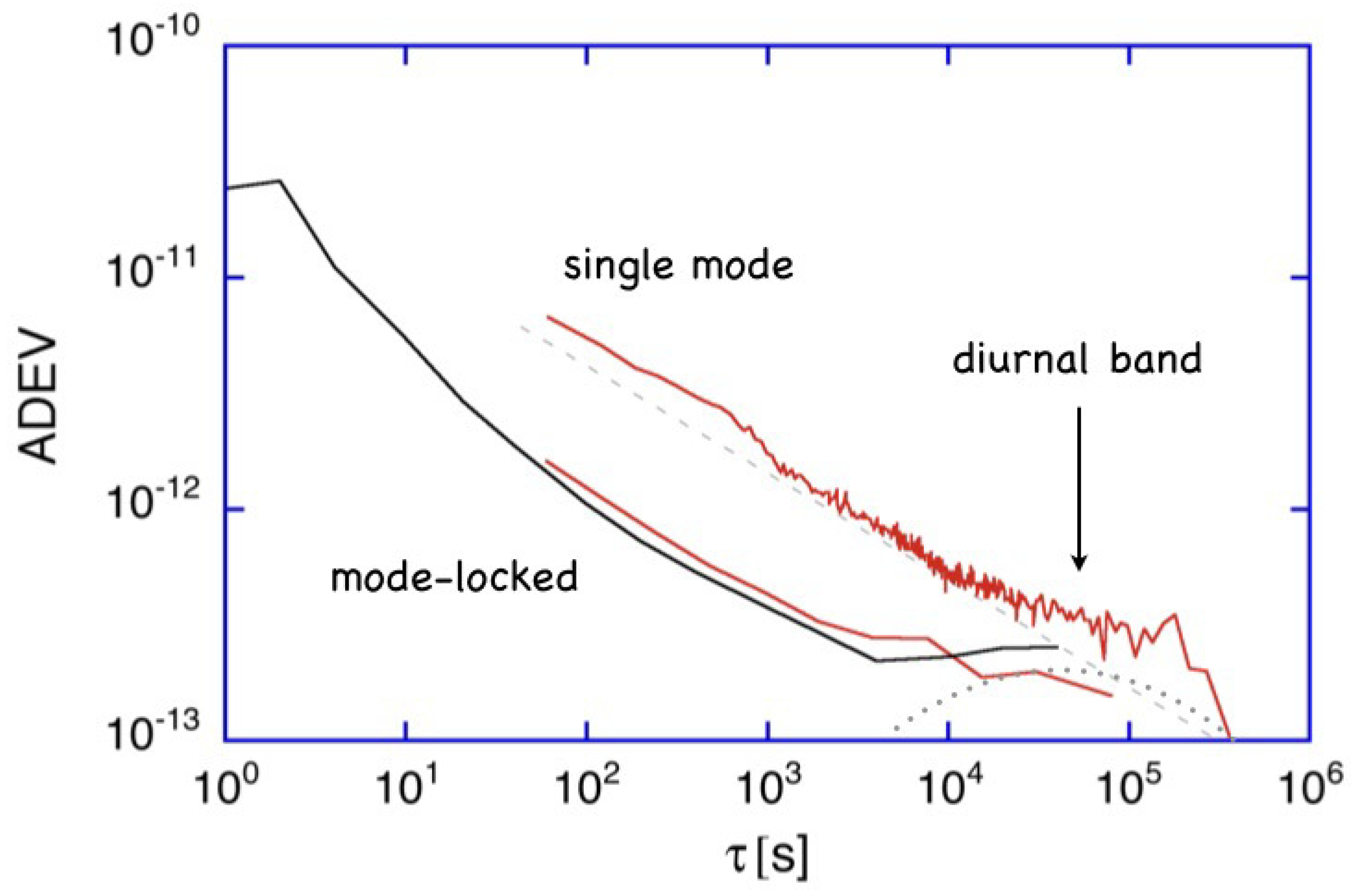
There are several groups of mechanisms that determine the actual performance of a large laser gyroscope in terms of sensitivity, stability and the extraction of physical measurements. Rotational signals of geophysical origin aside, small dither components from microseismic activity amongst them, there are time variable offsets arising from non-reciprocal effects between the two laser beams within the interferometer cavity. Furthermore, we must account for intrinsic limitations in the sensor stability as well as any deficits in the geophysical rotation models applied—either because of small model errors or because of data logging issues. Figure 1 gives an example.
From various measurement series under different operating conditions, we have generated an Allan deviation plot, characterizing the G ring laser. Two of these measurements were taken at higher output powers of around 40 nW, while the third was taken with the ring laser operating at a low power of approximately 5 nW. Everything else in the experiment remained the same. As might be expected, the higher optical power levels improve the overall detection sensitivity. The departure of the lowest curve from the expected slope of for integration times below 10 s is due to the microseismic background [17]. As indicated by the dashed line in the diagram, there appears to be a low level residual signal in the diurnal frequency band. This can be caused by a residual geophysical signal due to deficits in the formulation of the correction models or environmental deformation effects such as a changing atmospheric pressure loading. Since these perturbations become visible in the regime of rad/s, they are little more than one order of magnitude away from the Lense–Thirring frame dragging value of:
where G is the gravitational constant, M the mass, R the radius, the rotation rate of the Earth and is the latitude of the measurement device. For the location of the Geodetic Observatory Wettzell at a latitude of 49.145°, the expected value for is 85 mas per year (1.13 nrad/day) or rad/s. Figure 1 suggests that this measurement regime might become available for integration times much larger than 10 days, provided that the residual perturbations in the diurnal band can be resolved.
The fundamental limit on the rotational sensitivity of a laser gyroscope is set by the random phase walk induced by spontaneous emission in the cavity. This so-called quantum limit yields a resolution for a gyro of area A, perimeter P, quality factor Q, and operating on an optical frequency f given by:
In this expression, denotes the intra-cavity power per mode and t is the integration time [4,18]. Increasing the circulating laser power improves the sensor resolution, with all other system parameters remaining the same. However, the difference in sensitivity between the single mode ( mW) and the mode-locked ( mW) regime in Figure 1 is not related to variation in the quantum limit but rather the increased photon flux at the detector. The current resolution limit is not set by the gyroscope itself; it is rather given by the noise floor of the involved electronic components (amplifiers, detectors and the digitizer) and the applied frequency estimator. In the mode-locked regime of operation, although the gyro operates at more than one longitudinal laser mode, most of the beam power remains in the central mode. With increasing intensity, additional laser modes appear 112.4 MHz away from the dominant mode on each side. However, even in this case, 97% of the circulating laser power is contained in the dominant mode. Figure 2 represents a Fabry–Perot scan of the gyro cavity, where this situation is illustrated.
In order to measure small rotation rates like the Lense–Thirring frame dragging contribution, we have to consider three important areas, which are the effects caused by external sources of rotational signals, the sensor orientation and non-reciprocal errors from the sensor itself. The existence of an apparent perturbation at the diurnal frequency band clearly indicates that the signature of further signals such as loading effects from atmospheric and ocean tides and atmospheric and ocean angular momentum changes is still present in the observations. The same applies for the orientation of the gyroscope itself. A single component gyro is not able to establish the absolute value of a constant angular velocity, since the inner product of Equation (1) requires the exact knowledge of the orientation of the normal vector on the effective plane of the laser beam with a tolerance not exceeding 1 nrad. For a gyroscope with collinear to the Earth rotation axis, this condition relaxes considerably, because the argument in the cos function is practically one. Let us now turn to the third group of systematic errors, which are related to effects from non-reciprocal laser functions of the Sagnac interferometer. Here, we distinguish between effects that arise from the hot cavity and those that arise from the subsequent superposition of the two beams.
3. Intra-Cavity Perturbations
The greatest advantage of a ring laser cavity is the fact that it generates two beams traveling in opposite directions, occupying the same modal volume on exactly the same beam path. The larger the cavity becomes, the higher is the rotational sensitivity of the device. Fluctuations in the length of the cavity are common mode effects and largely cancel out during heterodyne detection. Therefore, a nearly monolithic square cavity enclosing an area of 16 m produces a clean unperturbed sinusoidal beat note and even the much larger heterolithic 834 m stainless steel cavity of UG2 shows only very small dithering effects [9]. However, even subtle changes at the level of of the optical frequency of one beam, which do not appear in the other beam, will cause a significant bias in the measurement, creating an offset, which is more than a factor of 1000 larger than the Lense–Thirring frame dragging effect.
3.1. Backscatter Correction
The most important contribution to the experimentally measured sensor drift is the backscatter coupling between the two counter-propagating laser beams, which causes frequency pulling and pushing. This quantity is not constant as a function of time, but strongly depends on the backscatter phase. Variations in ambient temperature and atmospheric pressure cause a tiny change in the physical separation of the mirrors and hence a slow shift in the backscatter coupling. While atmospheric pressure variations can be controlled with the installation of a pressure stabilizing vessel, which isolates the ring laser from the rest of the laboratory, changes in temperature are not controllable for a structure as large as G. While the temperature inside the ring laser vessel only drifts at a level of 3–5 mK per day, following the annual temperature cycle of the seasons, this is enough to cause a significant drift of the measured interferometer beat note. By observing the amount of backscattered light in each of the laser beams, a correction value can be computed according to [19] as:
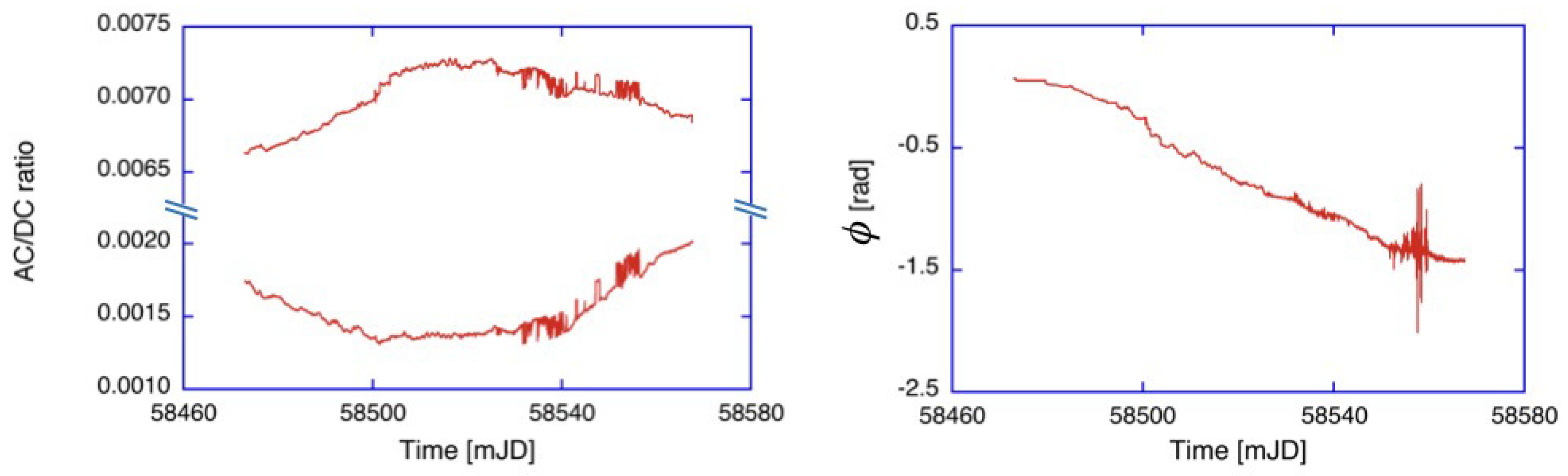
where and are the fractional beam modulations and the phase angle between them. For a given mirror quality, and scale approximately as for a cavity of linear size L. The ratio of the correction to the observed interferometer beat note to the beat note itself scales approximately as . This shows how important it is to make the ring laser cavity as large as possible, while sufficient mechanical stability of the entire structure still has to be maintained. In the absence of active control mechanisms, it appears that a symmetrical structure with a length of 6–10 m on a side is feasible for a large ring laser structure. Figure 3 shows the observed variation of the fractional beam modulations and the phase angle between them, over a period of more than 100 days. Since these data were taken with the atmospheric pressure stabilizing vessel in operation, the observed variations of the correction quantities are entirely caused by temperature variation.
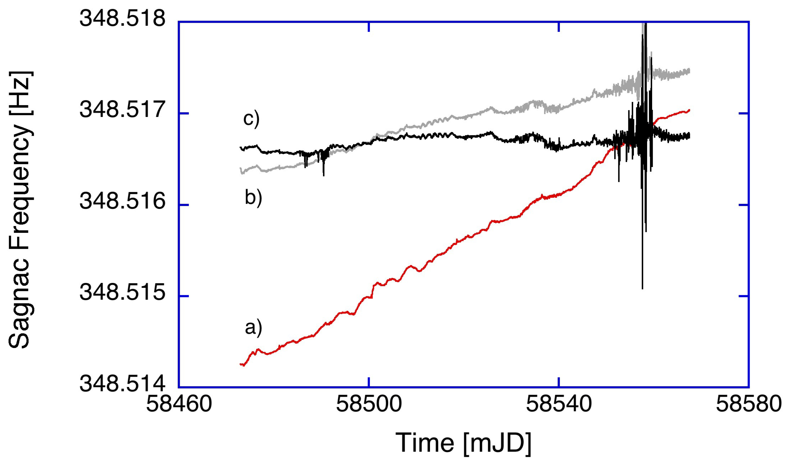
When the inferred correction is applied to the observations, we are able to reduce the long-term drift in the observation of the Earth rotation signal significantly. This is shown in Figure 4.
However, short-term fluctuations still remain in the measurement. Furthermore, there are now additional perturbations present in the processed signal. These are caused by insufficient fidelity of the estimates of the backscatter corrections. In particular, the uncertainties of the phase estimates towards the end of the dataset cause considerable errors. The remaining apparent drift of the measured rotation rate points to another error source that needs to be removed. As the power between the two counter-propagating beams in the ring cavity are not equal, we observe a frequency drift of the interferogram, resulting from dispersion as the optical frequency drifts. We have repeatedly measured the optical frequency of the counter-clockwise beam in the resonator. Over 30 days, this adds up to about 10 MHz. For these measurements, we have operated the system under a pressure stabilizing vessel. This leaves the temperature, trending downward linearly over the period of the measurement and hence the cavity length as the only variable parameter. The resultant correction for the dispersive frequency shift is shown in Figure 4 for the full dataset. Although it is possible to remove the sensor drift entirely, the data remain compromised by the limited signal-to-noise ratio of the in situ measurements of the correction parameters and other much smaller measurement error sources.
3.2. Intensity Dependence of the Frequency of the Beat Note
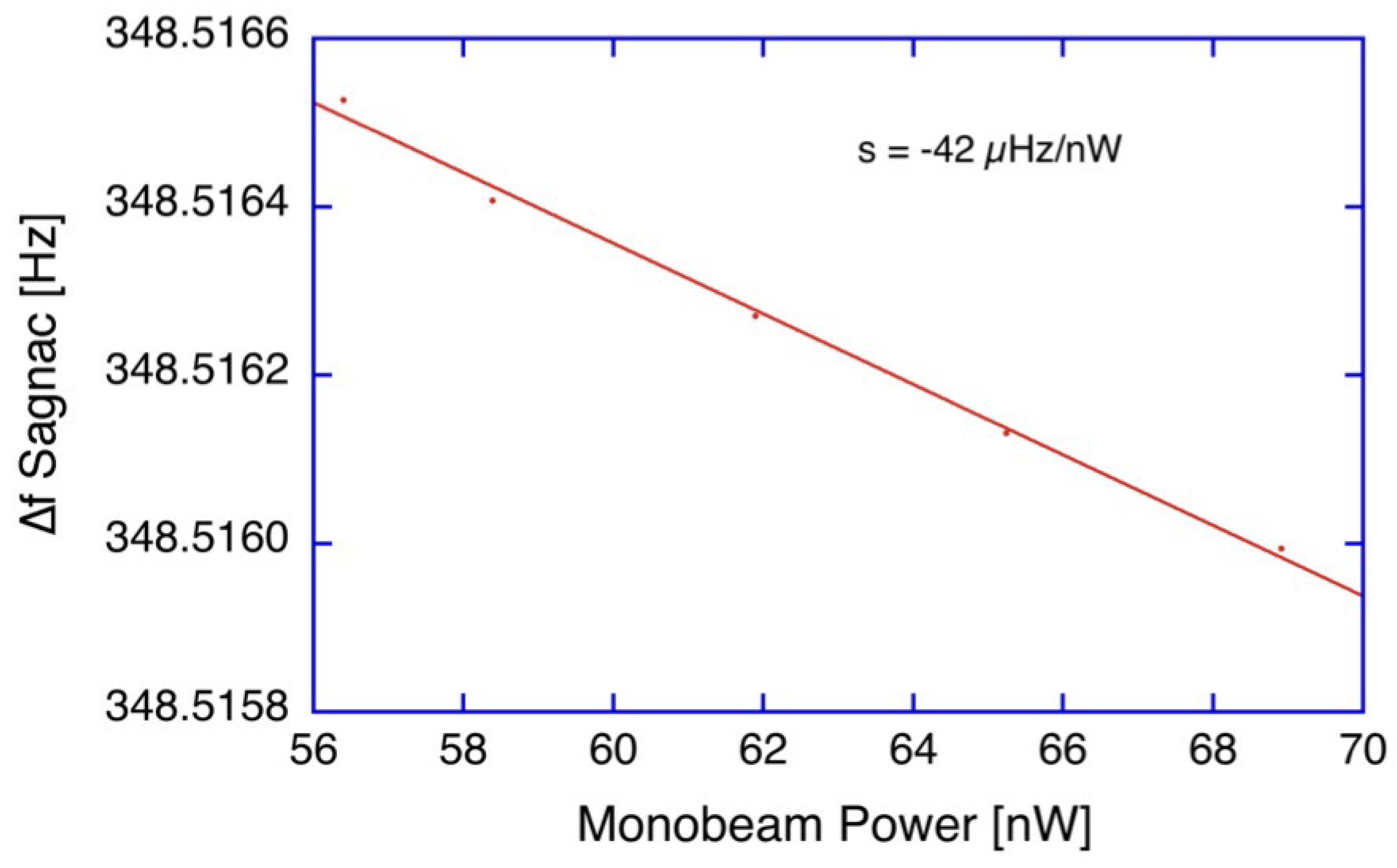
The square cavity of the G ring laser has four supermirrors as the only intra-cavity surfaces for the laser beam to interact with. The presence of the 5 mm diameter capillary of the gain section may add an additional quantum of loss, due to possible vignetting of the laser beam. Nevertheless, we find that the cavity is not entirely reciprocal with respect to the losses experienced by the two counter-propagating laser beams. There is a small difference of about 1% in beam power between the clockwise and the counter-clockwise laser beam of the G ring. This leads to a small non-reciprocal frequency pulling effect, which exhibits some dependence on the circulating optical power in the ring cavity. Figure 5 illustrates the effect. We obtain a shift in the beat note of the interferometer of −42 Hz/nW of measured output power. This places serious constraints on the stability required of the laser output power.
For normal operation of the G ring laser, we employ a feedback loop that stabilizes the beam power level. This works very well over short periods of a few days but may not be entirely adequate for a long data run in excess of 100 days. Some small scale variations of the beam power due to electrical ground potential fluctuations of the reference voltage or even fluctuations in the electronic comparator circuitry cannot be ruled out. This in turn leads to small variations in brightness and hence a variable bias to the measured Sagnac frequency. In order to guard against this effect, we have localized the feedback control loop as well as possible. The reference voltage, the brightness detector and the laser beam excitation are all located on a small electronic circuit board with a common ground connection and short leads.
4. Extra-Cavity Perturbations
For a complete error budget, it is not enough to only consider intra-cavity effects that perturb the proportionality of the observed laser beat note and the rotational motion experienced by the gyroscope. The data acquisition system as well as the beam recombination process can also introduce systematic errors. Here, we discuss the most obvious potential error sources.
4.1. Data Acquisition Noise
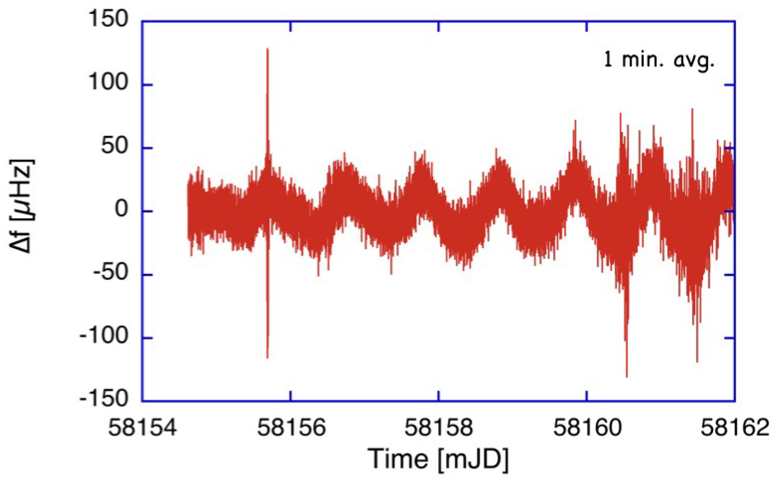
The application of selected low noise photo-detectors (Hamamatsu C10439-01, Hamamatsu Photonics, Hamamatsu, Japan), together with the introduction of the FFT based digital Buneman frequency estimator from the National Instruments Labview package (National Instruments Corporation, Austin, TX, USA), reduced the noise level of the Sagnac frequency estimates over the previously applied HUV2000B photodiode detectors and the autoregressive AR2 frequency estimator [20] by more than 10 dB, when averaging over time intervals of one-minute duration. As a result, we can now estimate the Sagnac beat note f with an uncertainty of about 30 Hz peak to peak or 12 Hz rms; previously, this was almost 100 Hz peak to peak or 25 Hz rms. Figure 6 shows an example of a current measurement series for a length of one week.
The measurements show the increased stability obtained from the backscatter correction model and the significantly reduced noise level on the measurements. The spike on the second day is caused by oscillations from tele-seismic Love wave excitations caused by a remote earthquake. Towards the end of the time window, we note an increasing noise level. This too is a measurement signal, which is caused by a higher level of micro-seismic activity, usually originating from storms over the Atlantic ocean. At best, G now reaches a noise floor of just below 10 Hz over one hour, which is not far away from the low noise boundary permitted by the ring laser location in the Bavarian Forest.
4.2. Frequency Drift Effects from External Components
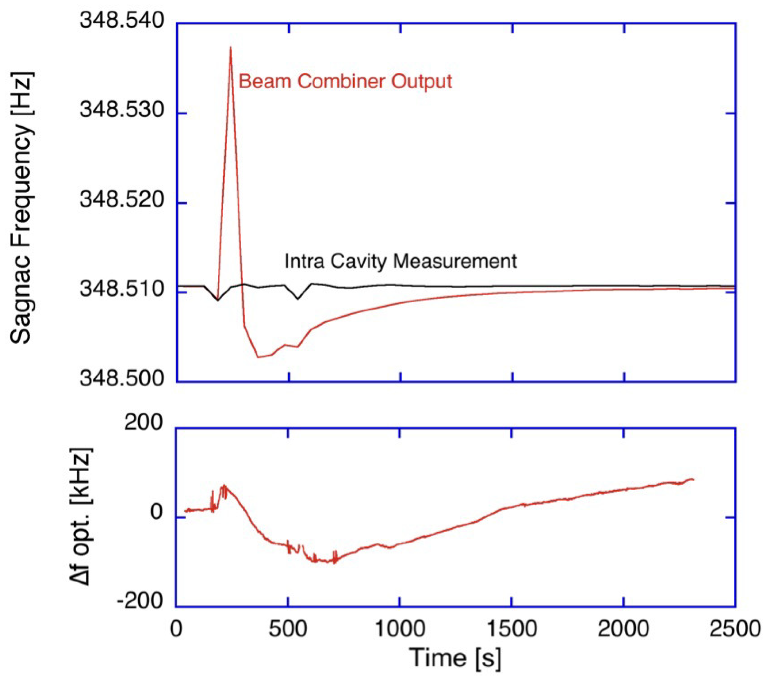
All of the ring laser gyroscopes developed within our working group follow the same design concept. An externally imposed rotational signal is measured via the frequency difference of the two counter-propagating laser beams in a square or rectangular, traveling wave, and ring resonator. The interferogram, however, is obtained from an external Mach–Zehnder interferometer, which is attached to the body of the cavity and combines the two laser beams. It redirects the light of each beam leaking through one of the mirrors and superimposes them on a non-polarizing 1:1 beamsplitter. In the case of the G ring laser, this beam combiner is realized in the form of a prism, made of two BK7 glass parts, glued together with an amplitude dividing coating in the middle. When the ambient temperature changes, a temperature gradient between the two halves of the prism can occur, which generates a phase shift between the two interfering beams and thus alters the beat frequency obtained from the Mach–Zehnder beam-combiner. Figure 7 illustrates this effect for the G ring laser, when the combining prism was gently warmed up for a few seconds with the help of a warm air blower.
The interferogram of the two counter propagating laser beams experiences a shift of more than 25 mHz as a temperature gradient develops across the beam combining prism. As a reference point, the requirement for the measurement of variations in the length of day demands a stability of the order of 1 Hz over several weeks.
While this warm-up experiment was carried out, we also evaluated the Sagnac frequency directly from each of the two counter-propagating laser beams from the cavity of the Sagnac interferometer by looking at the beat note induced by the backscatter process. This frequency estimate is available independently from each beam, albeit with a much smaller signal-to-noise ratio than the combined beam. The black line in the top part of Figure 7 indicates no appreciable change on the intra-cavity Sagnac frequency, apart from two small perturbations, when we entered and subsequently left the ring laser laboratory for the heat blower experiment. Evaluating the optical frequency of the counter-clockwise beam from the Sagnac interferometer leads to a similar conclusion. Over one hour around the manipulation of the beam combiner temperature, as expected, we find very little effect on the ring cavity itself, since the variation of the optical frequency of the interferometer stayed well within ±200 kHz (Figure 7 bottom).
5. Materials and Methods
The G-ring is situated in southeastern Germany at the Geodetic Observatory Wettzell (latitude N 49.145°, longitude E 12.88°). It is housed in a purpose built underground laboratory. The monument supports a polished granite table upon which the laser rests with protection against external influences. The laser itself is made of highest quality zerodur. Four bars were rigidly attached to a base plate forming the edges of a square with a 4 m side length, yielding a free spectral range of 18.75 MHz. The four mirrors and their mirror holders were attached at the face sides of the bars by molecular adhesion. This technique ensured a stable vacuum seal. The mirrors were of extreme quality, having losses of about 12 parts per million. The ring laser structure of G was designed to be mechanically very stable. Throughout the year, the laboratory temperature changed by no more than ±0.5 degrees due to the annual cycle of the seasons, with a day-to-day drift of temperature typically below 5 mK. Scale factor variations due to the variation of the atmospheric pressure are shielded effectively by an actively controlled pressure stabilizing vessel.
6. Conclusions
The accuracy of large ring laser gyroscopes are significantly more than an order of magnitude away from any meaningful attempt at terrestrial detection of general relativistic precessions, such as the Lense–Thirring/frame dragging effect. Having said that, they already possess the raw sensitivity to achieve this goal. At this stage, their useable sensitivity is dominated by geometric instabilities in the instrument itself, noise contributions from the detection systems as well as deficits in the models used to isolate geophysical signals. These latter contributions can come from amplitude or phase errors or from an altogether incomplete model. None of these shortcomings are insurmountable. Some important progress has already been made, in particular with respect towards the establishment of an absolute scale factor [16].
Author Contributions
Conceptualization, K.U.S. and J.-P.R.W.; methodology, A.G., J.K. and C.L.A.; software, A.G.; validation, A.G., K.U.S. and J.-P.R.W.; formal analysis, C.L.A. and J.K.; investigation, J.K. and A.G.; data curation, A.G. and J.K.; writing—original draft preparation, K.U.S. and J.-P.R.W.; writing—review and editing, J.-P.R.W. and K.U.S.; visualization, K.U.S.; supervision, K.U.S. and J.-P.R.W.; funding acquisition, K.U.S. and J.-P.R.W.
Funding
This research was supported by the Deutsche Forschungsgemeinschaft: Grant No. SCHR 645/6-1, the Bundesamt fuer Kartographie and Geodaesie and Dodd–Walls Centre for Photonics and Quantum Technologies.
Acknowledgments
C.L.A. acknowledges the support of the University of Canterbury and Dodd–Walls Centre for Photonic and Quantum Technologies for the provision of PhD scholarships.
Conflicts of Interest
The authors declare no conflict of interest.
References
- Schiff, L.I. Possible new experimental test of general relativity theory. Phys. Rev. Lett. 1960, 4, 215. [Google Scholar] [CrossRef]
- Everitt, C.W.F.; DeBra, D.B.; Parkinson, B.W.; Turneaure, J.P.; Conklin, J.W.; Heifetz, M.I.; Keiser, G.M.; Silbergleit, A.S.; Holmes, T.; Kolodziejczak, J.; et al. Gravity Probe B: Final results of a space experiment to test general relativity. Phys. Rev. Lett. 2011, 106, 221101. [Google Scholar] [CrossRef] [PubMed]
- Abbott, B.P.; Abbott, R.; Abbott, T.D.; Abernathy, M.R.; Acernese, F.; Ackley, K.; Adams, C.; Adams, T.; Addesso, P.; Adhikari, R.X.; et al. Observation of gravitational waves from a binary black hole merger. Phys. Rev. Lett. 2016, 116, 061102. [Google Scholar] [CrossRef] [PubMed]
- Schreiber, K.U.; Wells, J.P.R. Invited review article: Large ring lasers for rotation sensing. Rev. Sci. Instrum. 2013, 84, 041101. [Google Scholar] [CrossRef] [PubMed]
- Macek, W.M.; Davis, D.T.M., Jr. Rotation rate sensing with travelling wave ring lasers. Appl. Phys. Lett. 1963, 2, 67–68. [Google Scholar] [CrossRef]
- Jacobs, S.F.; Zanoni, R. Laser ring gyro of arbitrary shape and rotation axis. Am. J. Phys. 1982, 50, 659–660. [Google Scholar] [CrossRef]
- Hurst, R.B.; Wells, J.P.R.; Stedman, G.E. An elementary proof of the geometric dependence of the Sagnac effect. J. Opt. A Pure Appl. Opt. 2007, 9, 838. [Google Scholar] [CrossRef]
- Stedman, G.E.; Bilger, H.R.; Ziyuan, L.; Poulton, M.P.; Rowe, C.H.; Vetharaniam, I.; Wells, P.V. Canterbury ring laser and tests for non-reciprocal phenomena. Aust. J. Phys. 1993, 46, 87–102. [Google Scholar] [CrossRef]
- Hurst, R.B.; Stedman, G.E.; Schreiber, K.U.; Thirkettle, R.J.; Graham, R.D.; Rabeendran, N.; Wells, J.P.R. Experiments with an 834 m2 ring laser intererometer. J. Appl. Phys. 2009, 105, 113115. [Google Scholar] [CrossRef]
- Anyi, C.L.; Thirkettle, R.J.; MacDonald, G.J.; Schreiber, K.U.; Wells, J.P.R. Gyroscopic operation on the 3s2⟶2p10 543.3 nm transition of neon in a 2.56 m2 ring Cavity. Opt. Lett. 2019, 44, 3074–3077. [Google Scholar] [CrossRef] [PubMed]
- Schreiber, K.U.; Klügel, T.; Velikoseltsev, A.; Schlüter, W.; Stedman, G.E.; Wells, J.P.R. The large ring laser G for continuous earth rotation monitoring. J. Pure Appl. Geophys. 2009, 166, 1485–1498. [Google Scholar] [CrossRef]
- Schreiber, K.U.; Gebauer, A.; Wells, J.P.R. Long term frequency stabilisation of a 16 m2 ring laser gyroscope. Opt. Lett. 2012, 37, 1925–1927. [Google Scholar] [CrossRef] [PubMed]
- Schreiber, K.U.; Gebauer, A.; Wells, J.P.R. Closed loop locking of an optical frequency comb to a large ring laser. Opt. Lett. 2013, 38, 3574–3577. [Google Scholar] [CrossRef] [PubMed]
- Schreiber, K.U.; Klügel, T.; Wells, J.P.R.; Hurst, R.B.; Gebauer, A. How to detect the chandler and the annual wobble of the earth with a large ring laser gyroscope. Phys. Rev. Lett. 2011, 107, 173904. [Google Scholar] [CrossRef] [PubMed]
- Bosi, F.; Cella, G.; Di Virgilio, A.; Ortolan, A.; Porzio, A.; Solimeno, S.; Cerdonio, M.; Zendri, J.P.; Allegrini, M.; Belfi, J.; et al. Measuring gravitomagnetic effects by a multi-ring-laser gyroscope. Phys. Rev. D 2011, 84, 122002. [Google Scholar] [CrossRef]
- Hurst, R.B.; Mayerbacher, M.; Gebauer, A.; Schreiber, K.U.; Wells, J.P.R. High accuracy absolute rotation rate measurements with a large ring laser: Establishing the scale factor. Appl. Opt. 2017, 56, 1124–1130. [Google Scholar] [CrossRef] [PubMed]
- Tanimoto, T.; Hadziioannou, C.; Igel, H.; Wasserman, J.; Schreiber, K.U.; Gebauer, A. Estimate of rayleigh-to-love wave ratio in the secondary microseism by colocated ring laser and seismograph. Geophys. Res. Lett. 2015, 42, 2650–2655. [Google Scholar] [CrossRef]
- Dorschner, T.A.; Haus, H.A.; Holz, M.; Smith, I.W.; Statz, H. Laser gyro at the quantum Limit. IEEE J. Quantum Electron. 1980, QE-16, 1376–1379. [Google Scholar] [CrossRef]
- Hurst, R.B.; Rabeendran, N.; Schreiber, K.U.; Wells, J.P.R. Correction of backscatter-induced systematic errors in ring laser gyroscopes. Appl. Opt. 2014, 53, 7610–7618. [Google Scholar] [CrossRef] [PubMed]
- King, B.T. Application of superresolution techniques to ring laser gyroscopes: Exploring the quantum limit. Appl. Opt. 2000, 39, 6151–6157. [Google Scholar] [CrossRef] [PubMed]
Figure 1.
The performance of the G ring laser at the Geodetic Observatory Wettzell under different operating conditions.
Figure 1.
The performance of the G ring laser at the Geodetic Observatory Wettzell under different operating conditions.

Figure 2.
Fabry–Perot scan of the G ring cavity. At a measured output power of approximately 40 nW, additional longitudinal laser modes appear at a frequency of 6 times the free spectral range (FSR) away from the dominant mode on each side.
Figure 2.
Fabry–Perot scan of the G ring cavity. At a measured output power of approximately 40 nW, additional longitudinal laser modes appear at a frequency of 6 times the free spectral range (FSR) away from the dominant mode on each side.

Figure 3.
The parameters , and of the backscatter correction (Equation (4)) of a time series of about 100 days in length. Due to the mechanically monolithic construction of the G ring laser and the active pressure stabilized environment of the gyroscope, there are only small changes in the backscatter pulling observable.

Figure 4.
The backscatter corrected Earth rotation rate over 100 days of observation. Each data point was averaged over one hour and the known geophysical signals have been removed from the measurements. The abscissa shows the measured Sagnac frequency with (a) representing the raw data; (b) the same dataset after the correction for the backscatter coupling. The final result is shown in (c) when dispersive effects from the drifting optical frequency are removed.

Figure 5.
Dependence of the ring laser beat note on the measured output power.

Figure 6.
One-minute averages of the recorded Earth rotation rate of the G ring laser at the Geodetic Observatory Wettzell. The rms scatter corresponds to 30 Hz of scatter for the beginning of the time series.
Figure 6.
One-minute averages of the recorded Earth rotation rate of the G ring laser at the Geodetic Observatory Wettzell. The rms scatter corresponds to 30 Hz of scatter for the beginning of the time series.

Figure 7.
The effect of a small temperature gradient applied to the beam combining prism at the output of the Sagnac interferometer. While the combined beam experiences a more than 25 mHz variation of the beat note, the ring interferometer remains almost unperturbed (top chart), as well as the optical frequency inside the ring cavity (bottom chart).

© 2019 by the authors. Licensee MDPI, Basel, Switzerland. This article is an open access article distributed under the terms and conditions of the Creative Commons Attribution (CC BY) license (http://creativecommons.org/licenses/by/4.0/).
Share and Cite
MDPI and ACS Style
Schreiber, K.U.; Gebauer, A.; Kodet, J.; Anyi, C.L.; Wells, J.-P.R. Rotation Sensing Lasers in General Relativity: Some Technical Notes and Current Advances. Universe 2019, 5, 190. https://doi.org/10.3390/universe5090190
AMA Style
Schreiber KU, Gebauer A, Kodet J, Anyi CL, Wells J-PR. Rotation Sensing Lasers in General Relativity: Some Technical Notes and Current Advances. Universe. 2019; 5(9):190. https://doi.org/10.3390/universe5090190
Chicago/Turabian StyleSchreiber, K. Ulrich, André Gebauer, Jan Kodet, Caroline L. Anyi, and Jon-Paul R. Wells. 2019. "Rotation Sensing Lasers in General Relativity: Some Technical Notes and Current Advances" Universe 5, no. 9: 190. https://doi.org/10.3390/universe5090190
Note that from the first issue of 2016, this journal uses article numbers instead of page numbers. See further details here.