
An Agent-Based Architecture of the Digital Twin for an Emergency Department

1
University Lyon, INSA Lyon, University Jean Monnet Saint-Etienne, University Claude Bernard Lyon 1, University Lumière·Lyon 2, DISP UR4570, 69621 Villeurbanne, France
2
University Lorraine, CNRS, CRAN UMR 7039, University Lorraine, 54000 Nancy, France
*
Author to whom correspondence should be addressed.
†
These authors contributed equally to this work.
Sustainability 2023, 15(4), 3412; https://doi.org/10.3390/su15043412
Submission received: 10 January 2023
/
Revised: 25 January 2023
/
Accepted: 8 February 2023
/
Published: 13 February 2023
(This article belongs to the Special Issue Industry 4.0 in Support of Process Transformation)
Abstract
:The concept of Digital Twin (DT) seems promising to improve the management of patient pathways in Emergency Departments (EDs). This article proposes an agent-based architecture of a DT designed for that purpose. The core of this DT is its Information System (IS), which is regularly synchronised on the IS of the Physical Twin (PT). The agents model the ED’s resources (equipment and staff) and patients in the DT and update this information in the DT’s IS. This article shows how such a DT may operate in three modes: (0) “Digital Shadow” to monitor the ED’s current state in real time, (1) “Synchronised DT” to monitor the ED’s current and future states according to a predictive simulation, and (2) “Exploratory DT” in order to perform Monte Carlo simulations of various future states. Mode (1) is the main contribution. This proposition is illustrated in a simulation of the ED in order to demonstrate the capabilities.
1. Introduction
Improving patient flows in organisations or care pathways has been a topic of increasing interest for decades. The multitude of actors and their interactions are such that it is still difficult to adequately address this issue. The hospital and its gateway, the Emergency Department (ED), is therefore the main system in which a significant improvement of the patient pathway may be envisaged.
Today, with the renewed interest in Artificial Intelligence methods, a new era in the management of hospital systems organisation and patient flow is arising. This digital transformation is often likened to that of Industry 4.0. Of all the concepts and approaches encompassed in the Industry 4.0 paradigm, Digital Twin (DT) is a particularly promising path to improve ED performance. It offers faster access to data captured on the floor and provides a digital support framework enhanced with simulations and data analysis [1].
An abundant literature exists on DT applied to various domains [2,3]. One definition is that “DT consists of a virtual representation of a production system that is able to run on different simulation disciplines, characterised by the synchronisation between the [digital] and [physical] systems, by means of data and connected smart devices, mathematical models and real time data elaboration” [4]. DTs are used when there is a need for (i) a control as close as possible to the physical system and (ii) an anticipation of its behaviour, through the integration of simulation. This work is based on Kritzinger et al.’s one [5] which defines a DT as a digital system with an automatic data flow both from and to the PT. In their definitions, the PT and physical system are synonymous, but not DT and digital system. For instance, a Digital Shadow is a digital system monitoring a PT that is not a DT. The same definitions as [5] are used here, except for DT which is refined as “Synchronised DT” and “Exploratory DT”.
In the aforementioned work [5], the data flows between the DT and the PT are automatic, implying an absence of decisions taken by a stakeholder. Nevertheless, due to the human-based nature of the studied system, this work emphasises the integration of the human in the decision loop for a better suppor, and hence, a DT is defined here as a decision-support system that controls a PT.
The contribution of this work is to propose an architecture of DT that relies on agent-based simulation, i.e., all aspects of communication, infrastructure, and data modelling lie beyond the scope of this paper. To focus on the simulation architecture without being disturbed by these aspects, the PT is emulated through simulation rather than using a real one. In this context, the transitions of the digital agents (in this article, the word “agent” always refers to the digital counterpart of a (human or material) resource or patient) have a name starting with either ds_ (for “Digital Shadow”) when they take part in the synchronisation with the PT, or with sim_ (for simulation) when they are involved in interactions with other agents. As a consequence, the proposed digital system may operate in one of three modes depending on the type(s) of transition activated:
- Digital Shadow (only ds_* transitions) is a visualisation/monitoring of the current PT state;
- Synchronised DT (both ds_* and sim_* transitions at the same time) provides a “real-time” predictive image of the future of the system, allowing for performance trajectories to be tracked and for decision makers to anticipate potential problems with “what-if” analyses;
- Exploratory DT (only sim_* transitions) provides the various types of AnyLogic experiments (Monte Carlo simulations with parameter variations, optimisation with the OptQuest engine, etc.) to analyse “what-if” scenarios.
The outline is as follows. Section 2 reviews the literature on DT architecture on one hand and on simulation and DT applied to EDs on the other hand. Section 3 presents the proposed architecture of a DT, and Section 4 presents an application to a simulated ED. Section 5 discusses this proposition. Section 6 concludes.
2. State of the Art
2.1. DT Architectures Overview
The evolution of the DT definition provided by Errandonea et al. [6] has gone from asset simulation and virtual replica to an idea of a multi-technological environment or platform converging towards a physical object and virtual space [7,8]. Since the introduction of the concept of DT, numerous attempts have been made to define and specify more accurately the meaning of the concept, yet there is no unique definition accepted by the scientific community. For instance, Semeraro et al. [7] identified over 30 definitions of the concept, and from their analysis, they propose a generalisation: “A set of adaptive models that simulate the behaviour of a physical system in a virtual system getting real time data to update itself along its life cycle. The DT replicates the physical system to predict failures and opportunities for changing, to prescribe real time actions for optimising and/or mitigating unexpected events observing and evaluating the operating profile system”.
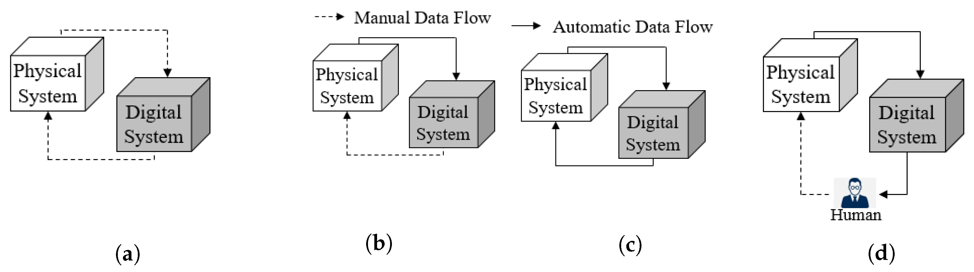
Kritzinger et al. [5] define a DT as a digital system with an automatic data flow both from and to a PT. When this flow is automatic from the PT to the digital system only and manual in the other direction, they call the digital system a digital shadow. Below, their figures are reproduced in Figure 1a–c as this work is based on their definitions. In fact, a DT is seen here as the convergence of an IS and a simulation, or in other words, the concept of DT increases the dynamism of an IS by not only recording the past and present states of the PT, but also forecasting its future by simulation.
One key aspect in the deployment of a DT is the definition of its architecture. Numerous DT architectures have been proposed in the literature–some papers review them [3,7]. Among the most referenced architectures, one may cite [1,2,9,10,11,12,13,14], to name a few. Nevertheless, all these DT architectures are fully compliant with Kritzinger’s taxonomy and thus define automatic flows of data between DT and the PT. This positioning is not consistent with the point of view on a DT defended in this work, with a clear integration of the human in the decision loop.
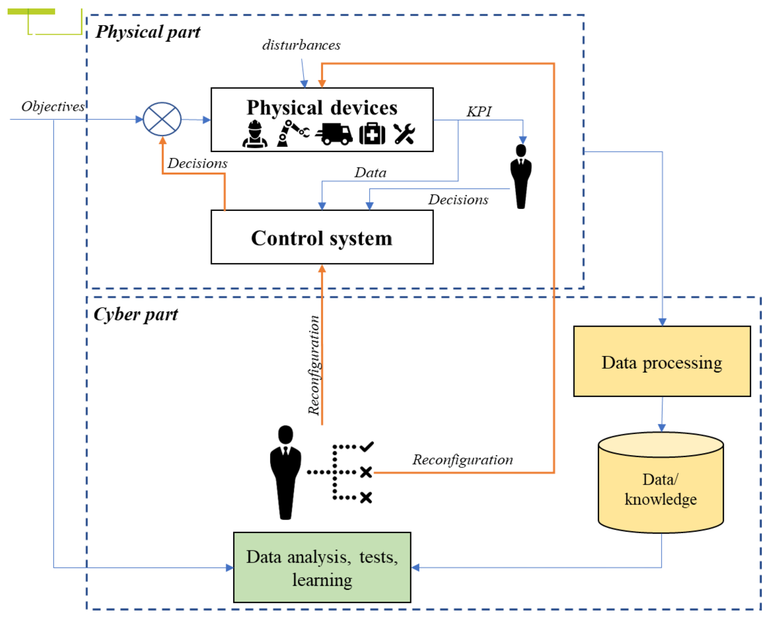
In a domain close to the concept of DT, Cyber Physical Production Systems are “systems of systems of autonomous and cooperative elements connected with each other in situation dependent ways, on and across all levels of production, from processes through machines up to production and logistics networks, enhancing decision making processes in real time, response to unforeseen conditions and evolution along time” [15]. From all existing architectures in this context, the one by Cardin et al. [16] illustrates the positioning between the physical part and the cyber (i.e., digital) part, with a clear integration of the human in the decision loop (Figure 2).
2.2. Simulations and Digital Twins for Healthcare Systems
Simulation has been widely reported in the literature as a means to improve patient pathways, especially in EDs. This literature primarily includes Discrete Event Simulation (DES) [17,18] and Agent-Based Simulation (ABS) [19,20,21], with possible hybridisation DES + ABS [22,23]. Yet, all these works on simulations mostly propose “what-if” scenarios for improvement, whereas these results are offline, and the input of data into simulation models is known to be a very difficult and tedious task. As stated in the introduction, the DT approach seems promising to further develop the use of simulations directly connected to physical systems.
The application of DT in the context of healthcare systems is currently garnering keen interest. While some authors focus on developing a DT for specific patients to improve their health in interaction with healthcare systems [24,25], the focus here is on developing a DT for the ED system alone. In 2019, Patrone et al. [26] reviewed the literature on DT and/or simulations involved in decision support systems and applied to healthcare systems. Only three papers were explicitly about DT [27,28,29]. Since that review, the subject has gained interest [30,31,32,33,34,35] (cf. also DT for Healthcare by GE (https://www.gehccommandcenter.com/digital-twin accessed on 7 February 2023)), hence, the novelty of this work.
The benefits of using DTs are almost never clearly affirmed in the aforementioned works, such as the reduction of patients’ waiting time or length of stay, the more efficient and precise planning of resources, and so on. In their conclusion, the authors of [35] claim that Digital Twin will assist with achieving sustainable and efficient healthcare facility management.
From Patrone et al.’s review, one can understand that all previous work focuses on the fact that simulation is the heart of a DT, with data input in real time from the PT through the Internet of Things. Yet, no details on the architecture of DTs and the interactions with decision makers are provided.
Nevertheless, with the definitions proposed by Kritzinger et al. [5], one can say that simulation models described at the beginning at this section are Digital Models, whereas the research works claiming to be Digital Twin are closer to Digital Shadow. The next section explores all these facets in order to propose an architecture of the DT.
3. Architecture of a Digital Twin (DT)
3.1. DT Typology
Figure 1a–c recall how Kritzinger et al. [5], respectively, define a digital model, a digital shadow, and a DT, depending on how the digital system is connected to the physical system (PT).
In these definitions, physical system and the PT are synonymous, but a digital system may not be a DT. Figure 1c is understood to deal with automation, that is, when the time delay is too short for humans to provide feedback. Since the priority is to propose a DT for operational decisions—with a time range between minutes and weeks—Figure 1d is proposed as an evolution of Figure 1c to include a human decision maker in the decision loop. A human in the loop is added because:
- All models are false: The digital system relies on a model which, by definition, is not a reproduction but a simplified representation of the reality. Some events occurring in the PT (e.g., failures, arrivals of patients, etc.) may be wrong or absent from the digital system, in which case the digital system has to re-synchronise on the PT. On the other hand, if the digital system simulates events not present in the PT, then the digital system is wrong and, again, the digital system has to re-synchronise on the PT, not the other way around. This explains why the solutions generated by decision support systems (for planning, scheduling, etc.) are rarely applied to physical systems directly, but are often manually adapted beforehand.
- Two systems cannot control each other: If two systems control each other, then they either both do exactly the same thing, or, most frequently, block each other, and nothing happens in both of them.As a consequence of this and the previous bullet points, the PT has to be the master and the digital system a slave. This slave may suggest actions to—but cannot control—the PT. This master/slave relationship complies with the next bullet point.
- The digital system must be as non-invasive as possible: This may not be the case for all kinds of production systems, but one can assume that a healthcare system requires tools that suggest actions—rather than give orders—and that they update these suggestions whenever the digital system detects that they are not followed in the PT. In fact, caregivers—especially highly qualified staff such as doctors—already make decisions and may thus sometimes disagree with the suggestions of the digital system.
When including a human decision maker inside the digital system, the aim is not to only provide a framework making all information explicit and available to the decision maker whenever s/he needs to make a decision (such a situation corresponds to a Digital Shadow), but it is also designed to capture the complete decision inside the system PT + DT, hence updating the DT as automatically as possible.
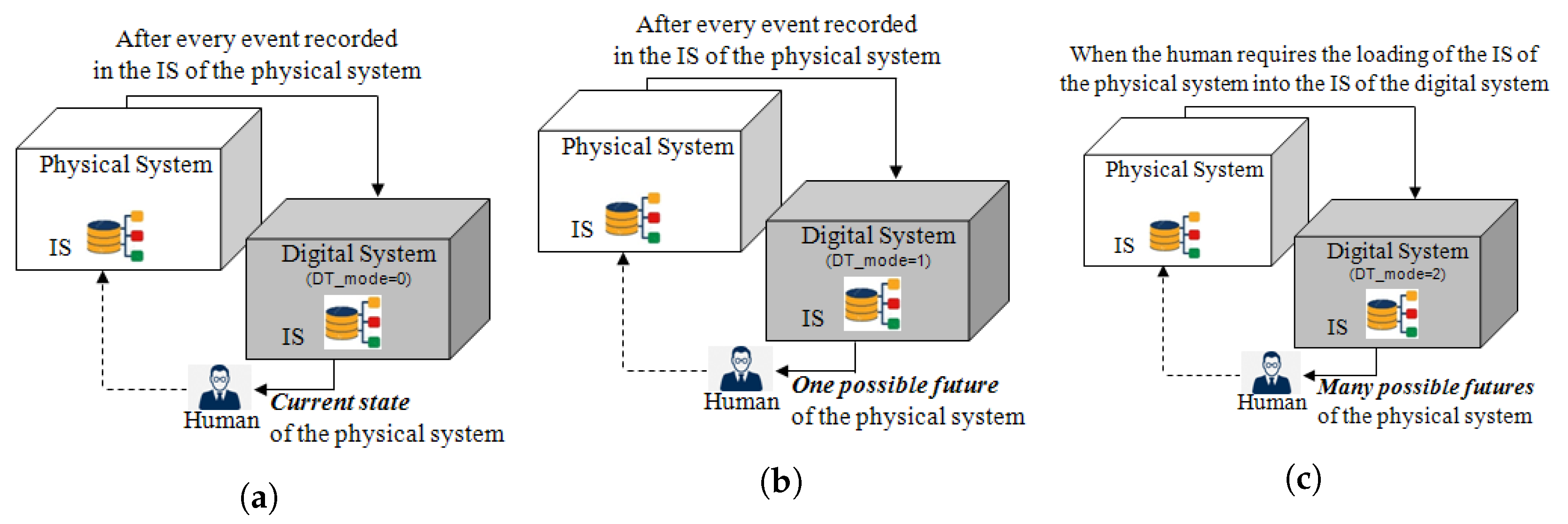
The proposed refinement on Kritzinger et al. [5]’s DT taxonomy is now explained. This version relies on the difference between sim_* and ds_* transitions. As previously said, sim_* transitions model interactions with other agents in the digital system in order to perform simulations, while ds_* transitions re-synchronise these agents on their counterpart in the PT. All ds_* transitions have at least the condition “DT_mode <= 1”, and sim_* have “DT_mode >= 1”. Consequently, the value of DT_mode selects one of the three modes of the digital system detailed in Figure 3:
- Digital Shadow: Figure 3a corresponds to “DT_mode” in which only ds_* transitions are activated. The names of these transitions come from “Digital Shadow” which means that the state of agents monitors only the state of their PT counterparts,
- Synchronised DT: Figure 3b corresponds to “DT_mode” in which both ds_* and sim_* transitions are activated. This DT is called “synchronised” because the ds_* transitions re-synchronise its agents on the PT whenever an event is saved in the IS of the PT. Between two such events, sim_* transitions make its agents simulate one possible future when “DT_acceleration_factor ”. (All time-dependent sim_* transitions have a duration divided by Parameter DT_acceleration_factor, such that, for example, “DT_acceleration_factor ” makes Mode “Synchronised DT” behave like “Digital Shadow”.) Section 5 discusses the possibility to simulate other possible futures in Monte Carlo simulations.
- Exploratory DT: Figure 3c corresponds to “DT_mode” in which only sim_* transitions are activated. Since ds_* transitions are not used, this mode first requires that all agents be initialised according to a file saving the content of the IS of the PT and next that sim_* transitions simulate as many futures as wished (Monte Carlo simulations) with various scenarios/parameters,
In synthesis, the Mode “Digital Shadow” mainly corresponds to a digital dashboard automatically fed with data from the PT. The Mode “Exploratory DT” is used to perform “What-If” simulations offline and proposes decision support to decision makers; it is thus a classical decision-support tool based on simulations automatically initialised with “real data”. With this synchronisation, the Mode “Synchronised DT” can be seen as a synthesis of the two other modes, i.e., a digital dashboard fed with both real-time data and results of simulations, allowing the decision maker to have a better insight into the potential futures.
The novelty of this work is both the proposition of the Mode “Synchronised DT” and the capability for the decision maker to easily switch from one mode to another in the same environment.
3.2. Technical Architecture of Digital System
This subsection first explains the choice of relying on an Agent-Based Simulation (ABS) to implement the proposed digital system. It next presents the steps of its implementation. This digital system is modelled with library “Agent” in AnyLogic 8.
3.2.1. Rationale for Relying on ABS
Unlike most of the literature on DTs for production systems, the authors think that ABS is more relevant for a digital system than a traditional Discrete Event Simulation (DES) because:
- ABS allows various levels of abstraction: The developers of AnyLogic ([36], p. 13) claim that ABS allows for both higher and lower abstraction levels than traditional DES. This allows a digital system to be started as a coarse model and then gradually refined.
- DT as a system of systems: Indeed, one can use agent-based modelling to link digital systems together to create higher-level digital systems. For instance, the DTs of various resources (based on CAD or DES models, for example) and patients (modelling their genome, physiological characteristics, or lifestyle) may be connected to one another to produce the DT of a production system such as an ED. The interactions (discussion between such models and inclusion of one such model in another one) are what agents focus on.
3.2.2. Implementation Process Overview
As previously stated, three main modes are implemented in the DT to give access to different decision supports. To obtain these modes, a three-step implementation is required:
- Step 1:
- Digital system withsim_*transitions only: First, an ABS of the PT is implemented with no connection to the PT, i.e., the digital system operates as a Digital Shadow. More precisely, populations of agents are created here, with the corresponding expected behaviour.
- Step 2:
- Digital system withds_*transitions only: Here, the digital system is put in the Mode “Exploratory DT” only, in which all agents are synchronised with events coming from the PT. The authors assume here that all the information requested by the digital system is saved in the IS of the PT, and the state of the digital system is synchronised on the PT’s IS (rather than the PT itself).
- Step 3:
- Digital system with bothsim_*andds_*transitions: The Mode “Synchronised DT” requires the digital system to both simulate (with sim_* transitions) and synchronise on the PT (with ds_* transitions), which needs the addition of the synchronisation state sr_resynchronise to all agents.
More details for each step are proposed hereafter in the use case description.
4. Use Case of an Emergency Department (ED)
4.1. Use Case Description
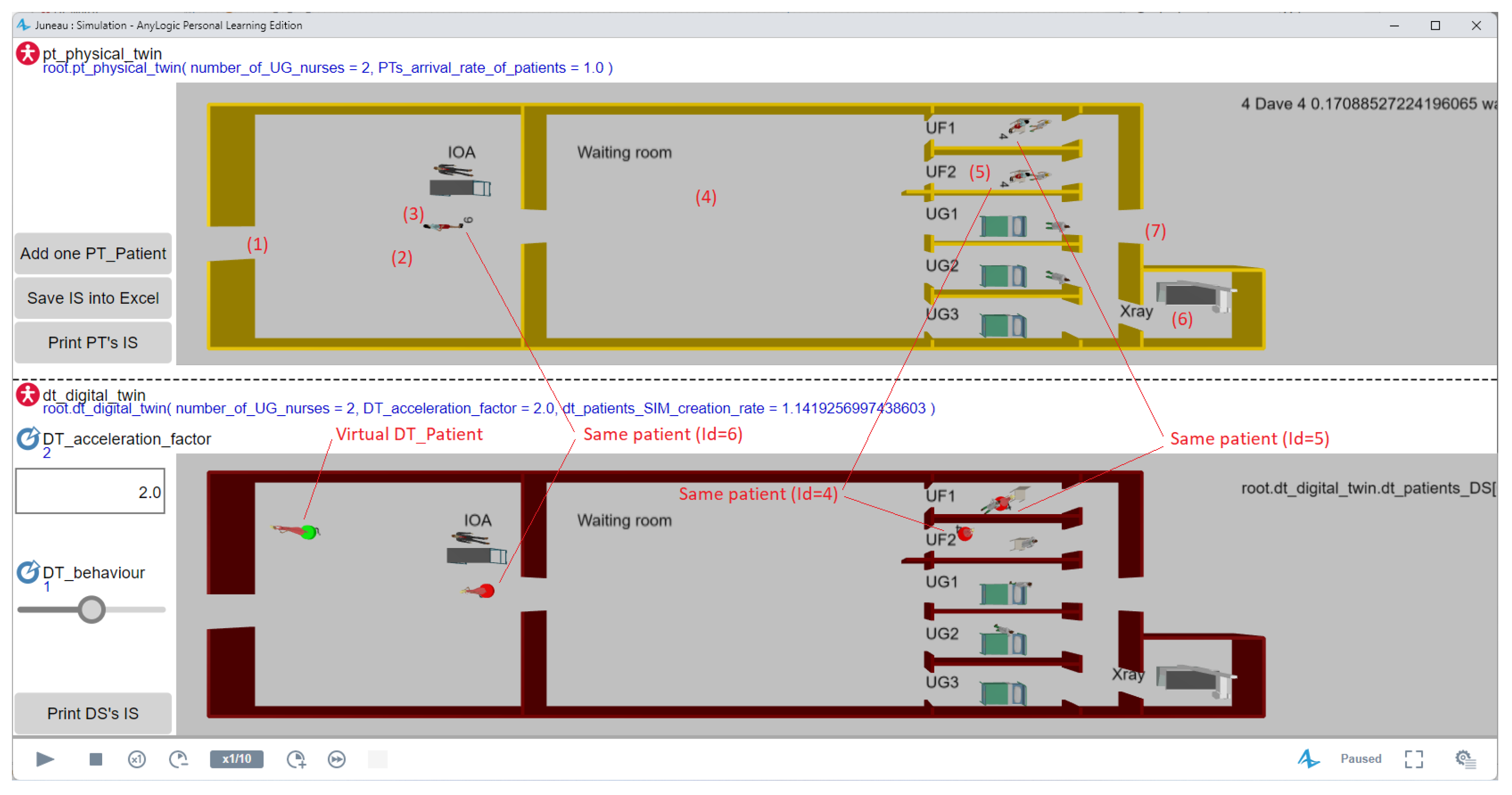
The 3D window on top of Figure 4 shows the use case considered for the PT. The seven numbers between parentheses in this figure show the following steps of the process:
- A patient arrives at the ED (left door); and
- Enters the waiting line of the IOA (Infirmière d’Organisation de l’Accueil, i.e., triage nurse);
- Once available, the IOA determines the class of path (UG when the severity is 1 or 2 for serious cases, or UF when severity equals 3, 4, or 5 for light problems);
- The patient goes to the waiting room;
- Once available, a nurse calls the patient to a box and prescribes care;
- Potentially, the patient may go to the X-ray room when available, and
- the patient leaves the ED.
4.2. Implementation Details
4.2.1. Implementation Step 1: Digital System with sim_* Transitions Only
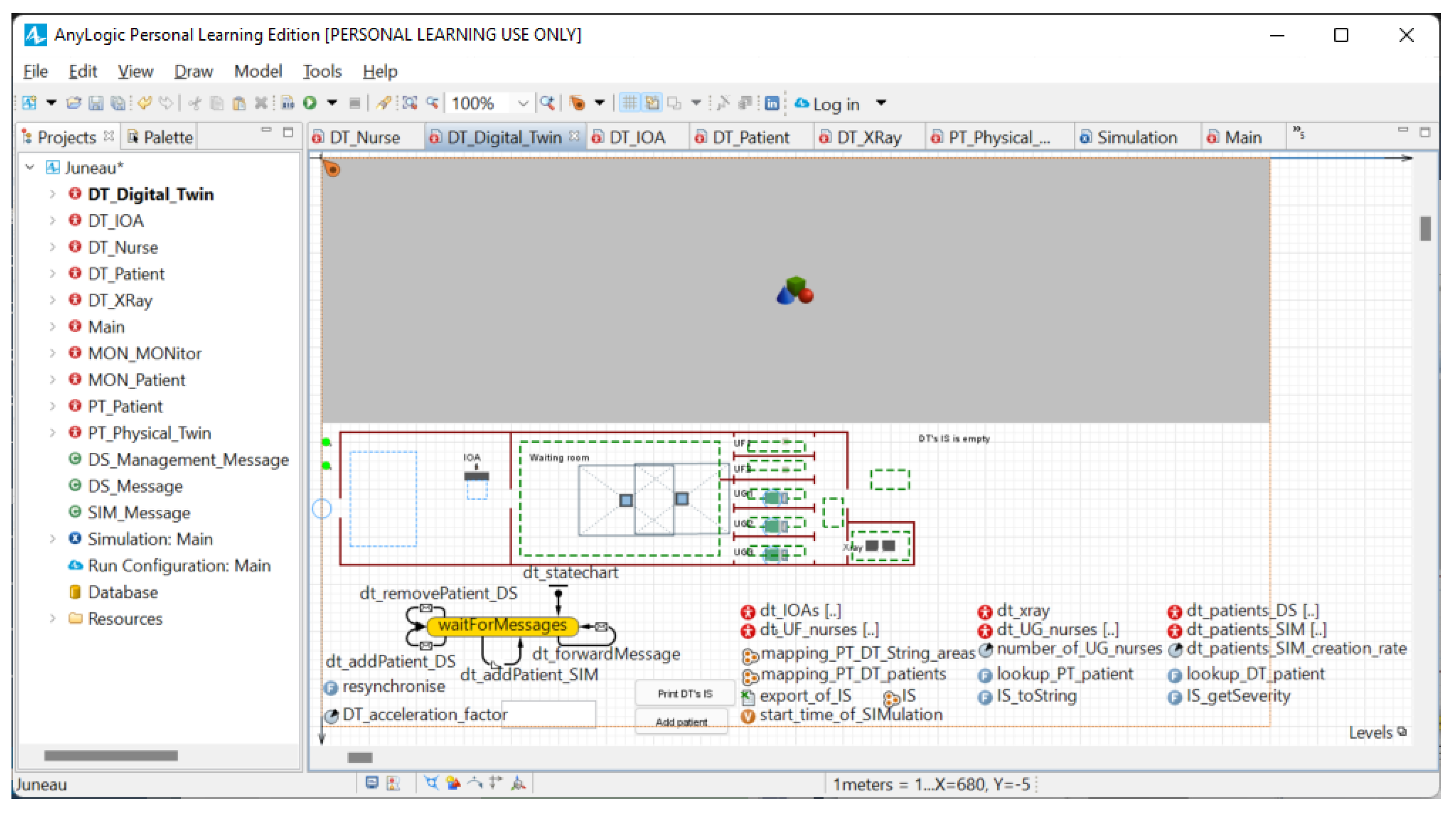
As described, populations of (resource and patient) agents are created here. Figure 5 shows all the elements in the work (left) and the model of Agent DT_Digital_Twin (right).
In AnyLogic, red disk icons represent agents. Double-clicking such red icons in the left-hand side tab in Figure 5 opens the editor of this type of agent in the other tab. The right-hand side tab in Figure 5 shows that Agent DT_Digital_Twin has a state chart with a single (yellow) state waitForMessages to add (Transitions dt_addPatient_DS and dt_addPatient_MON (Section 4 will explain that every instance of DT_Patient corresponds to either (i) a real patient in the PT shown with a green disk in Figure 4 and added by dt_addPatient_DS whenever a real patient enters the PT, or (ii) a simulated patient shown with a red disk and randomly added by dt_addPatient_MON when the digital system simulates one possible future of the PT. This ability of simulating the future also explains that the digital system has a copy of the information system of the PT (cf. IS in Figure 5)) and removes (Transition dt_removePatient_DS) DT_Patients from the digital system, and forwards messages from the PT to the agents (Transition dt_forwardMessage). The right-hand side tab in Figure 5 also shows that DT_Digital_Twin contains six populations of agents (dt_IOAs[…], dt_xray[…], …, dt_patients_SIM[…]). (Similarly, Agent Main contains an instance of DT_Digital_Twin and an instance of the PT_Physical_Twin because the PT is simulated.)
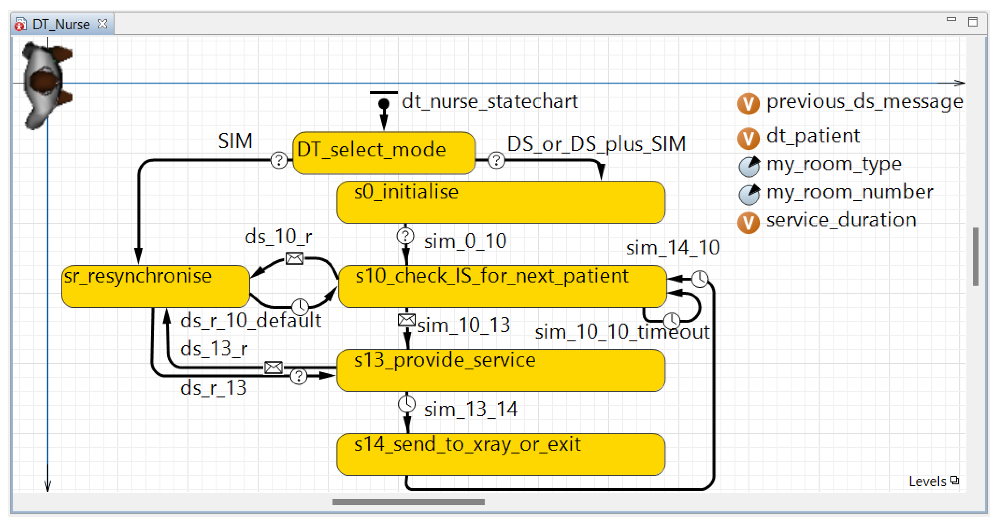
Figure 6 gives details on the behaviour of one of the types of agents “living” in DT_Digital_Twin, namely DT_Nurse. This figure illustrates again that all the proposed agents are modelled as states and transitions. A name starting with sim_ is given to the transitions and a name starting with sXX_ to the states (where “s” means “state” and “XX” is the order of activation of this state, e.g., s13_provide_service runs after s12 in an agent not shown in this article). (Figure 6 is complete and hence also shows ds_* transitions, and sr_resynchronise and DT_select_mode states which will be described in the next subsections. Only the four states s0_initialise, s10_check_IS_for_next_patient, s13_provide_service and s14_send_to_xray_or_exit were added in this first step of development.)
Every sim_* transition either tests a condition (shown by a “?” on their arrow in Figure 6, e.g., sim_0_10), receives a message sent by another agent (represented by an envelope, e.g., sim_10_13), or are waiting times modelling the duration of a task (shown by a clock, e.g., sim_13_14).
When this first implementation step is finished, sim_* transitions are deactivated by adding the condition “DT_mode ” to all of them.
4.2.2. Implementation Step 2: Digital System with ds_* Transitions Only
The second development step starts by setting Parameter “DT_mode ” in order to put the digital system in the Mode “Exploratory DT”. Next, State sr_resynchronise and pairs of transitions entering and leaving this state are added. These transitions have a name starting with ds_. In every pair of these transitions: (i) the transition from state sXX_* to sr_resynchronise is the reception of a message from the PT whenever an event was recorded in its information system (IS), while (ii) the transition in the opposite direction makes the considered DT agent be in the same state as its PT counterpart (i.e., a nurse in the case of Figure 6, but this counterpart may be another type of resources or a patient). In other words, the authors assume that all the information requested by the digital system is saved in the IS of the PT, and the state of the digital system is synchronised on the PT’s IS (rather than the PT itself).
When this second implementation step is finished, the deactivation of ds_* transitions is allowed by adding “DT_mode ” to their condition.
4.2.3. Last Implementation Step: Digital System with Both sim_* and ds_* Transitions
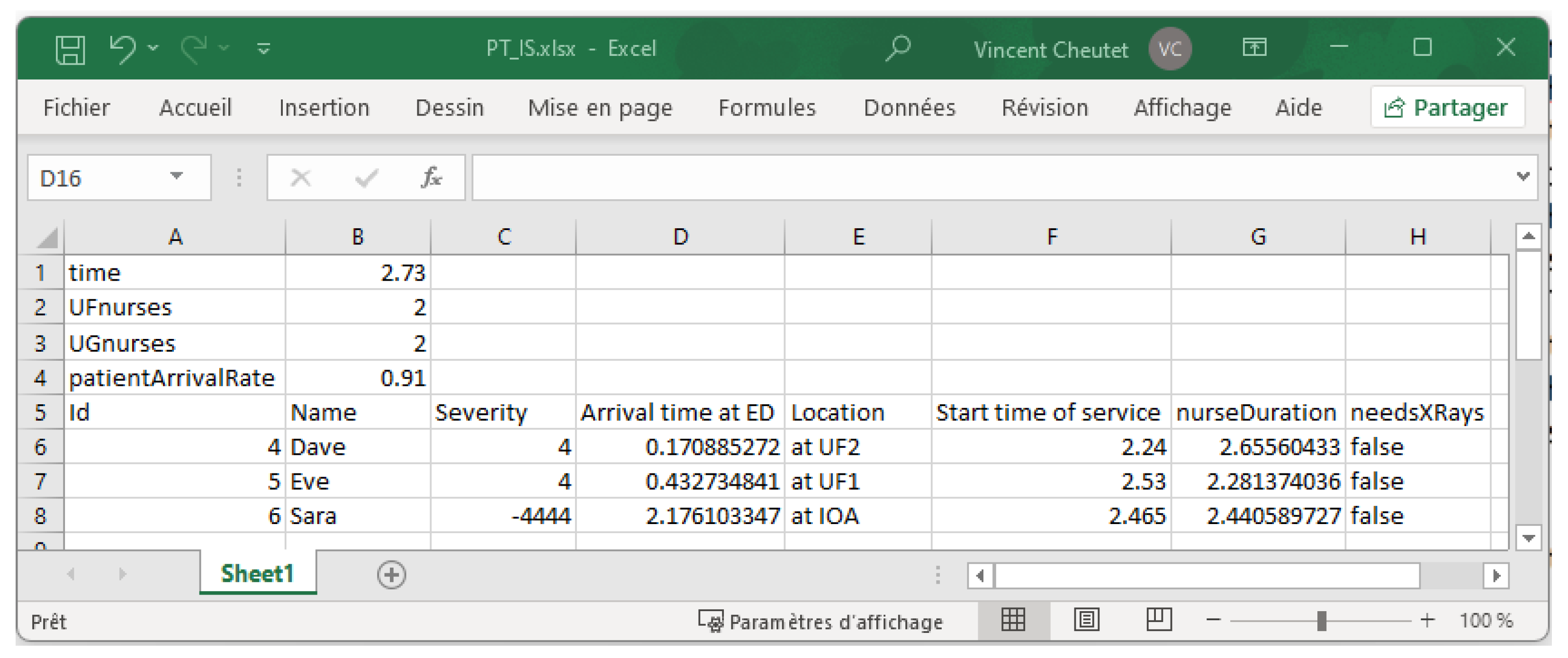
The third step of implementation makes sim_* and ds_* transitions work together by: (i) setting “DT_mode ”, (ii) dividing all time-dependent sim_* duration transitions by Parameter DT_acceleration_factor, (iii) adding State DT_select_mode and its two leaving transitions in Figure 6, and (iv) making the Mode “Exploratory DT” use State sr_resynchronise to initialise the digital model on a state of the PT previously saved in a file (Figure 7 shows an example of such a file).
Concerning (iv), please notice that Transition “SIM” points to sr_resynchronise while this state is not connected to sim_* transitions. This seems paradoxical, but this is a trick in order to implement the initial switch between states sXX_* in Mode “Exploratory DT” only once. Otherwise, its initialisation according to the aforementioned file would need the addition of the equivalent of sr_resynchronise and all its entering and leaving transitions. As a result, each agent uses State sr_resynchronise either (“DT_mode ” and “”) whenever a change in the PT is recorded in its IS and forwarded to the considered agent by Transition dt_forwardMessage in Figure 5, or (“DT_mode ”) only once at the initialisation of the digital system according to the content of IS saved in a file.
4.3. Use Case Analysis
The lower half of Figure 4 shows the digital system. It is running in Mode “Synchronised DT” (cf. DT_mode ) and twice as fast as the PT (cf. DT_acceleration_factor ). The lower 3D window shows three patient agents with a red disk at their feet because each of them corresponds to a real patient. A fourth patient agent has a green disk showing that it is virtual in the sense that it does not correspond to a real patient in the PT. Of course, all agents exist only in the digital system, but the word “virtual” means here that the green agents are randomly created by the digital system to simulate future arrivals of patients, and these ones are destroyed with each synchronisation of the digital system on the PT.
In Figure 4, DT_acceleration_factor is equal to two, but a typical use of the Synchronised DT will use a much larger value, in which case red patient agents quickly disappear and are replaced by green agents. The IS of the digital systems reflects this evolution and is hence different from the IS of the PT as long as no information is saved in the IS of the PT. Whenever saving in the IS of the PT does occur, the entire digital system is re-synchronised on the IS of the PT: (i) all green patient agents are removed; (ii) the state of every red patient agent is re-synchronised according to the information saved in the IS of the PT (i.e., according to a real patient); (ii’) similarly, care giver agents are also re-synchronised; and (iii) the content of the IS of the digital system is re-synchronised on the IS of the PT.
When the decision maker wants to change the mode of the digital system for “Exploratory DT”, (s)he clicks the button “Save IS into Excel”. The content of the Excel file shown in Figure 7 can then initialise the agents of an Exploratory DT.
5. Discussion and Future Works
The proposed architecture aims at providing several interaction types to decision makers and stakeholders more precisely and more consistently. Nevertheless, some issues are still open with these propositions.
First, the digital system is behind the PT because it synchronises according to the PT whenever a change is recorded in the IS of the PT. This delay may be short if caregivers update patients’ file after each medical treatment or long when caregivers first take care of all their patients, then update the IS at the end of their working day. This problem is the same as in industrial maintenance, where technicians also do their “real duty” first and the “paper work” as late as possible. The use of tablets with voice recognition motivates technicians to report their work more fully in the IS of their workshop, and one can expect that tablets will incur the same improvement in EDs.
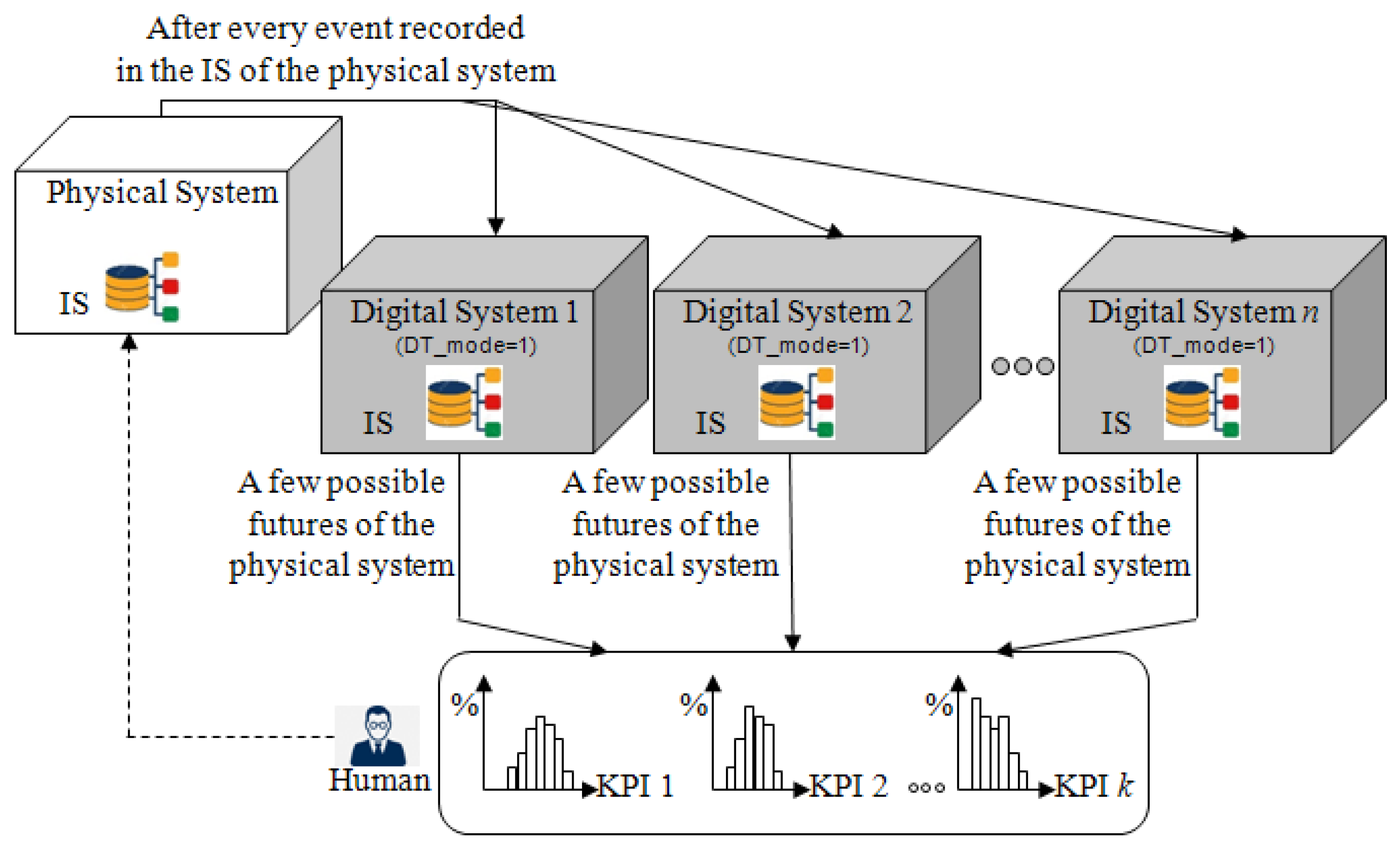
Next, the Synchronised DT in Figure 3b shows the current state of the implementation in which only one possible future is shown to the decision maker. Figure 8 shows how to modify this digital system in order to (1) perform Monte Carlo simulations (i.e., replicate the same simulation to show the variety of possible futures) and (2) study the expected impact of decisions (e.g., what may happen if Alice leaves at hh:mm).
Monte Carlo simulations: Replication of the variety of possible futures in a Synchronised DT can be obtained by () using n digital systems in parallel. Each of these simulates one replication, that is, one possible future, as shown in Figure 8, and () restarts each of the n digital systems when it has simulated a given duration (e.g, the next 24 h for an ED) in order to make each digital system perform more than just one replication.
After each replication has finished simulating this duration, some KPIs (Key Performance Indicators) will be saved to show histograms of the KPIs of all replications to the decision maker.
Next, Point requires re-synchronising each digital system on the PT after each end of a replication. Such a re-synchronisation can be obtained like in the Exploratory DT which uses an Excel file such as the one in Figure 7.
“What-If” analyses: The possibility to dynamically change decision variables in the proposed digital system is not yet implemented. More precisely, it is possible to change them (for instance, in AnyLogic experiments of the “Parameter variation” and “Optimisation” type), but they will be constant during a simulation run. Nevertheless, the dynamic nature of the Synchronised DT makes it more interesting to make decisions such as “Change this parameter at this time” (e.g., “keep the same number of UG nurses as in the Excel file until hh:mm, next remove one nurse” in order to study the consequence on the ED if Alice leaves at hh:mm).
Moreover, the histograms in Figure 8 do not show that they can be updated regularly. That is, whenever an event is recorded in the IS of the PT, the distribution of each KPI will be recomputed from the new state of the PT. The evolution of every KPI will thus be visible and used similarly to control charts; e.g., it will be possible to identify trends in order to detect problems before their occurrence [37,38].
Finally, an ED system is first a human-based organisation. The capture of the decision and the update of the PT are so much more complex than what has been proposed in this article, since all stakeholders have a free space to perform their tasks, and a consensus has to be reached very often. As a consequence, to really define a DT of an ED, an indirect capture of the decisions is needed, and an analysis of the system dynamics is promising [39].
6. Conclusions
Taking advantage of the current digitisation trend, the Digital Twin (DT) concept is seen as an opportunity to improve the control and management of complex organisations, especially Emergency Departments (EDs). A DT relies on simulation to anticipate the behaviour of the Physical Twin (PT). Yet, few initiatives have been developed in this respect. This research focuses on the architecture and the development of the specifications of the simulation core of a DT for an ED connected to a simulation of the PT. An Agent-Based Simulation (ABS) is used as it is recognised in the literature as a better reflection of the emergence of complex behaviours. The architecture proposes three operational modes to provide a decision maker with not only a 3D real-time visualisation (i.e., Digital Shadow) of the organisation’s behaviours, but also the analysis of what-if scenarios allowed by DT (as defined by [5]) with the possibility to track the decisions taken.
This work is a very first step towards a full DT for an ED. Future research will focus on the other classical dimensions of a DT: communication, data modelling, interoperability with hospital IS, human interfaces, and so on. Furthermore, since ED organisation is primarily based on human actions and decisions with various levels of knowledge, one can take advantage of the DT environment to analyse more closely the dynamics of an ED, the stability of decisions, and so on.
Author Contributions
Conceptualization, T.M., Y.L., G.B. and V.C.; methodology, T.M., Y.L., G.B. and V.C.; software, T.M.; writing—original draft, T.M. and V.C.; writing—review and editing, T.M., Y.L., G.B. and V.C. All authors have read and agreed to the published version of the manuscript.
Funding
This research received no external funding.
Institutional Review Board Statement
Not applicable.
Informed Consent Statement
Not applicable.
Data Availability Statement
Data sharing not applicable.
Conflicts of Interest
The authors declare no conflict of interest.
References
- Grieves, M.; Vickers, J. Digital twin: Mitigating unpredictable, undesirable emergent behavior in complex systems. In Transdisciplinary Perspectives on Complex Systems; Springer: Cham, Switzerland, 2017; pp. 85–113. [Google Scholar] [CrossRef]
- Tao, F.; Zhang, H.; Liu, A.; Nee, A.Y. Digital twin in industry: State-of-the-art. IEEE Trans. Ind. Inform. 2018, 15, 2405–2415. [Google Scholar] [CrossRef]
- Pystina, K.; Sekhari, A.; Gzara, L.; Cheutet, V. Digital Twin for production systems: A literature perspective. In Proceedings of the International Workshop on Service Orientation in Holonic and Multi-Agent Manufacturing, Cluny, France, 18–19 November 2021; Springer: Cham, Switzerland, 2021; pp. 103–117. [Google Scholar] [CrossRef]
- Negri, E.; Fumagalli, L.; Macchi, M. A review of the roles of digital twin in CPS-based production systems. Procedia Manuf. 2017, 11, 939–948. [Google Scholar] [CrossRef]
- Kritzinger, W.; Karner, M.; Traar, G.; Henjes, J.; Sihn, W. Digital Twin in manufacturing: A categorical literature review and classification. IFAC-PapersOnLine 2018, 51, 1016–1022. [Google Scholar] [CrossRef]
- Errandonea, I.; Beltrán, S.; Arrizabalaga, S. Digital Twin for maintenance: A literature review. Comput. Ind. 2020, 123, 103316. [Google Scholar] [CrossRef]
- Semeraro, C.; Lezoche, M.; Panetto, H.; Dassisti, M. Digital twin paradigm: A systematic literature review. Comput. Ind. 2021, 130, 103469. [Google Scholar] [CrossRef]
- ISO 23247; Automation Systems and Integration—Digital Twin Framework for Manufacturing. International Organization for Standardization: Geneva, Switzerland, 2021.
- Ponomarev, K.; Kudryashov, N.; Popelnukha, N.; Potekhin, V. Main principals and issues of digital twin development for complex technological processes. In Proceedings of the 28th DAAAM International Symposium, Zadar, Croatia, 8–11 November 2017; pp. 0523–0528. [Google Scholar] [CrossRef]
- Redelinghuys, A.; Basson, A.; Kruger, K. A six-layer digital twin architecture for a manufacturing cell. In Proceedings of the International Workshop on Service Orientation in Holonic and Multi-Agent Manufacturing, Bergamo, Italy, 11–12 June 2018; Springer: Cham, Switzerland, 2018; pp. 412–423. [Google Scholar] [CrossRef]
- Kaur, M.J.; Mishra, V.P.; Maheshwari, P. The convergence of digital twin, IoT, and machine learning: Transforming data into action. In Digital Twin Technologies and Smart Cities; Springer: Cham, Switzerland, 2020; pp. 3–17. [Google Scholar] [CrossRef]
- Boje, C.; Guerriero, A.; Kubicki, S.; Rezgui, Y. Towards a semantic Construction Digital Twin: Directions for future research. Autom. Constr. 2020, 114, 103179. [Google Scholar] [CrossRef]
- Aheleroff, S.; Xu, X.; Zhong, R.Y.; Lu, Y. Digital twin as a service (DTaaS) in industry 4.0: An architecture reference model. Adv. Eng. Inform. 2021, 47, 101225. [Google Scholar] [CrossRef]
- Wang, K.J.; Lee, Y.H.; Angelica, S. Digital twin design for real-time monitoring—A case study of die cutting machine. Int. J. Prod. Res. 2021, 59, 6471–6485. [Google Scholar] [CrossRef]
- Cardin, O. Classification of cyber-physical production systems applications: Proposition of an analysis framework. Comput. Ind. 2019, 104, 11–21. [Google Scholar] [CrossRef]
- Cardin, O.; Derigent, W.; Trentesaux, D. Digitalization and Control of Industrial Cyber-Physical Systems: Concepts, Technologies and Applications; John Wiley & Sons: Hoboken, NJ, USA, 2022. [Google Scholar]
- Bair, A.E.; Song, W.T.; Chen, Y.C.; Morris, B.A. The impact of inpatient boarding on ED efficiency: A discrete-event simulation study. J. Med. Syst. 2010, 34, 919–929. [Google Scholar] [CrossRef]
- Ben-Tovim, D.; Filar, J.; Hakendorf, P.; Qin, S.; Thompson, C.; Ward, D. Hospital event simulation model: Arrivals to discharge–design, development and application. Simul. Model. Pract. Theory 2016, 68, 80–94. [Google Scholar] [CrossRef]
- Laskowski, M.; Mukhi, S. Agent-based simulation of emergency departments with patient diversion. In Proceedings of the International Conference on Electronic Healthcare, London, UK, 8–9 September 2008; Springer: Berlin/Heidelberg, Germany, 2008; pp. 25–37. [Google Scholar] [CrossRef]
- Wang, L. An agent-based simulation for workflow in emergency department. In Proceedings of the 2009 Systems and Information Engineering Design Symposium, Charlottesville, VA, USA, 24 April 2009; pp. 19–23. [Google Scholar] [CrossRef]
- Liu, Z.; Rexachs, D.; Epelde, F.; Luque, E. An agent-based model for quantitatively analyzing and predicting the complex behavior of emergency departments. J. Comput. Sci. 2017, 21, 11–23. [Google Scholar] [CrossRef]
- Centeno, A.P.; Martin, R.; Sweeney, R. REDSim: A spatial agent-based simulation for studying emergency departments. In Proceedings of the 2013 Winter Simulations Conference (WSC), Washington, DC, USA, 8–11 December 2013; pp. 1431–1442. [Google Scholar] [CrossRef] [Green Version]
- Kaushal, A.; Zhao, Y.; Peng, Q.; Strome, T.; Weldon, E.; Zhang, M.; Chochinov, A. Evaluation of fast track strategies using agent-based simulation modeling to reduce waiting time in a hospital emergency department. Socio-Econ. Plan. Sci. 2015, 50, 18–31. [Google Scholar] [CrossRef]
- Liu, Y.; Zhang, L.; Yang, Y.; Zhou, L.; Ren, L.; Wang, F.; Liu, R.; Pang, Z.; Deen, M.J. A Novel Cloud-Based Framework for the Elderly Healthcare Services Using Digital Twin. IEEE Access 2019, 7, 49088–49101. [Google Scholar] [CrossRef]
- Angulo, C.; Ortega, J.A.; Gonzalez-Abril, L. Towards a Healthcare Digital Twin. In Artificial Intelligence Research and Development; IOS Press: Amsterdam, The Netherlands, 2019; pp. 312–315. [Google Scholar] [CrossRef]
- Patrone, C.; Galli, G.; Revetria, R. A state of the art of digital twin and simulation supported by data mining in the healthcare sector. In Advancing Technology Industrialization through Intelligent Software Methodologies, Tools and Techniques; IOS Press: Amsterdam, The Netherlands, 2019; pp. 605–615. [Google Scholar] [CrossRef]
- Bruynseels, K.; Santoni de Sio, F.; van den Hoven, J. Digital twins in health care: Ethical implications of an emerging engineering paradigm. Front. Genet. 2018, 9, 31. [Google Scholar] [CrossRef] [PubMed]
- Patrone, C.; Lattuada, M.; Galli, G.; Revetria, R. The role of internet of things and digital twin in healthcare digitalization process. In Proceedings of the World Congress on Engineering and Computer Science, San Francisco, CA, USA, 23–25 October 2018; Springer: Singapore, 2018; pp. 30–37. [Google Scholar] [CrossRef]
- Karakra, A.; Fontanili, F.; Lamine, E.; Lamothe, J.; Taweel, A. Pervasive Computing Integrated Discrete Event Simulation for a Hospital Digital Twin. In Proceedings of the 2018 IEEE/ACS 15th International Conference on Computer Systems and Applications (AICCSA), Aqaba, Jordan, 28 October–1 November 2018. [Google Scholar] [CrossRef]
- Croatti, A.; Gabellini, M.; Montagna, S.; Ricci, A. On the integration of agents and digital twins in healthcare. J. Med. Syst. 2020, 44, 1–8. [Google Scholar] [CrossRef] [PubMed]
- Erol, T.; Mendi, A.F.; Doğan, D. The Digital Twin Revolution in Healthcare. In Proceedings of the 2020 4th International Symposium on Multidisciplinary Studies and Innovative Technologies (ISMSIT), Istanbul, Turkey, 22–24 October 2020; pp. 1–7. [Google Scholar] [CrossRef]
- Mohapatra, S.; Bose, S. An appraisal of literature for design and implementation of developing a framework for digital twin and validation through case studies. Health Technol. 2020, 10, 1229–1237. [Google Scholar] [CrossRef]
- Chase, J.G.; Zhou, C.; Knopp, J.L.; Shaw, G.M.; Näswall, K.; Wong, J.H.; Malinen, S.; Moeller, K.; Benyo, B.; Chiew, Y.S.; et al. Digital Twins in Critical Care: What, When, How, Where, Why? IFAC-PapersOnLine 2021, 54, 310–315. [Google Scholar] [CrossRef]
- Alazab, M.; Khan, L.U.; Koppu, S.; Ramu, S.P.; Iyapparaja, M.; Boobalan, P.; Baker, T.; Maddikunta, P.K.R.; Gadekallu, T.R.; Aljuhani, A. Digital twins for healthcare 4.0-recent advances, architecture, and open challenges. IEEE Consum. Electron. Mag. 2022, 1–8. [Google Scholar] [CrossRef]
- Hassani, H.; Huang, X.; MacFeely, S. Impactful Digital Twin in the Healthcare Revolution. Big Data Cogn. Comput. 2022, 6, 83. [Google Scholar] [CrossRef]
- Grigoryev, I. AnyLogic 8 in Three Days. 2022. Available online: https://www.anylogic.com/upload/al-in-3-days/anylogic-in-3-days.pdf (accessed on 7 February 2023).
- Bouleux, G.; Marcon, E.; Mory, O. Early Index for Detection of Pediatric Emergency Department Crowding. IEEE J. Biomed. Health Inform. 2015, 19, 1929–1936. [Google Scholar] [CrossRef] [PubMed]
- Dugast, M.; Bouleux, G.; Mory, O.; Marcon, E. Improving Health Care Management Through Persistent Homology of Time-Varying Variability of Emergency Department Patient Flow. IEEE J. Biomed. Health Inform. 2019, 23, 2174–2181. [Google Scholar] [CrossRef] [PubMed]
- Itmi, M.; Cardon, A. Model for self-adaptive SoS and the control problem. In Proceedings of the 2010 5th International Conference on System of Systems Engineering, Loughborough, UK, 22–24 June 2010; pp. 1–6. [Google Scholar] [CrossRef]
Figure 1.
Digital Twin typology, with the first three representations coming from [5] and the last being the proposed adaptation: (a) Digital Model; (b) Digital Shadow; (c) initial DT concept; (d) updated DT concept with a human in the decision loop.
Figure 1.
Digital Twin typology, with the first three representations coming from [5] and the last being the proposed adaptation: (a) Digital Model; (b) Digital Shadow; (c) initial DT concept; (d) updated DT concept with a human in the decision loop.

Figure 2.
Architecture of Cyber Physical Production Systems [16].
Figure 2.
Architecture of Cyber Physical Production Systems [16].

Figure 3.
The three operation modes of the digital system in Figure 1d: (a) Digital Shadow: the digital system only uses ds_* transitions; (b) Synchronised DT: the digital system uses both ds_* and sim_* transitions; (c) Exploratory DT: the digital system only uses sim_* transitions.
Figure 3.
The three operation modes of the digital system in Figure 1d: (a) Digital Shadow: the digital system only uses ds_* transitions; (b) Synchronised DT: the digital system uses both ds_* and sim_* transitions; (c) Exploratory DT: the digital system only uses sim_* transitions.

Figure 4.
Emulation of the physical (top) and digital systems (bottom). Annotations are written in red, and digits between parentheses are explained in the text.
Figure 4.
Emulation of the physical (top) and digital systems (bottom). Annotations are written in red, and digits between parentheses are explained in the text.

Figure 5.
All agents (left) and model of the PT (right).

Figure 6.
The transitions of a DT_Nurse with a name starting with ds_* are activated when DT_mode , and the transitions starting by sim_* are activated when DT_mode .
Figure 6.
The transitions of a DT_Nurse with a name starting with ds_* are activated when DT_mode , and the transitions starting by sim_* are activated when DT_mode .

Figure 7.
Excel exporting the IS of the PT in Figure 4 to initialise an Exploratory DT.
Figure 7.
Excel exporting the IS of the PT in Figure 4 to initialise an Exploratory DT.

Figure 8.
Improvement on Figure 3b enabling Synchronised DT to carry out Monte Carlo simulations.
Figure 8.
Improvement on Figure 3b enabling Synchronised DT to carry out Monte Carlo simulations.

Disclaimer/Publisher’s Note: The statements, opinions and data contained in all publications are solely those of the individual author(s) and contributor(s) and not of MDPI and/or the editor(s). MDPI and/or the editor(s) disclaim responsibility for any injury to people or property resulting from any ideas, methods, instructions or products referred to in the content. |
© 2023 by the authors. Licensee MDPI, Basel, Switzerland. This article is an open access article distributed under the terms and conditions of the Creative Commons Attribution (CC BY) license (https://creativecommons.org/licenses/by/4.0/).
Share and Cite
MDPI and ACS Style
Moyaux, T.; Liu, Y.; Bouleux, G.; Cheutet, V. An Agent-Based Architecture of the Digital Twin for an Emergency Department. Sustainability 2023, 15, 3412. https://doi.org/10.3390/su15043412
AMA Style
Moyaux T, Liu Y, Bouleux G, Cheutet V. An Agent-Based Architecture of the Digital Twin for an Emergency Department. Sustainability. 2023; 15(4):3412. https://doi.org/10.3390/su15043412
Chicago/Turabian StyleMoyaux, Thierry, Yinling Liu, Guillaume Bouleux, and Vincent Cheutet. 2023. "An Agent-Based Architecture of the Digital Twin for an Emergency Department" Sustainability 15, no. 4: 3412. https://doi.org/10.3390/su15043412
Note that from the first issue of 2016, this journal uses article numbers instead of page numbers. See further details here.