
Comprehensive Characterization of Spent Chemical Foundry Sand for Use in Concrete
by
 ,
,
Paola Paul
1,2,*, 
Essia Belhaj
1,2,
Cécile Diliberto
3,
Komla Lolonyo Apedo
4 and
Françoise Feugeas
1,2 1
ICube Laboratory, UMR CNRS 7357, INSA de Strasbourg, 24 Boulevard de la Victoire, F-67084 Strasbourg, France
2
ICube Laboratory, University of Strasbourg, F-67000 Strasbourg, France
3
Institut Jean Lamour, UMR 7198 CNRS, Université de Lorraine, CNRS, IJL, F-54000 Nancy, France
4
ICube Laboratory, Université de Strasbourg, CNRS, 2 Rue Boussingault, F-67000 Strasbourg, France
*
Author to whom correspondence should be addressed.
Sustainability 2021, 13(22), 12881; https://doi.org/10.3390/su132212881
Submission received: 27 October 2021
/
Revised: 16 November 2021
/
Accepted: 18 November 2021
/
Published: 21 November 2021
Abstract
:The foundry industry generates large amounts of spent foundry sands, which are stored, available for recovery in other industrial sectors but unfortunately poorly exploited. Different authors have studied the possibility of recovering them in concretes, which would also allow production of more sustainable cementitious materials. The variability of their results highlights the importance of a better understanding of the potential influential parameters of the by-products. Unfortunately, exhaustive characterizations of the materials are rarely performed, especially for chemically bound foundry sands. This article presents a case study for the recovery of a spent chemical foundry sand with an exhaustive physicochemical characterization of the by-product and an analysis of its influence on the workability and mechanical strengths of cementitious materials. The tests recommended by the European standard for aggregates for concrete confirmed the suitability of the by-product. Associated with additional chemical tests (scanning electron microscopy, X-ray fluorescence, X-ray diffraction, etc.) as well as metallic particles characterization, they highlighted possible influential parameters. The workability and mechanical resistance tests carried out on mortars and concretes confirmed the influence of the fineness of the by-product associated with other parameters. Its use at a substitution rate of 30% results in a strength class C 30/37 concrete.
1. Introduction
Foundry sand is a high-quality sand bonded with either organic or inorganic binders [1] and used in foundries for more than 70% of the metal castings [2]. The raw sand is usually a high-quality silica sand, but other minerals can also be used such as chromite. The binder, which can be either inorganic or organic, ensures that the sand particles bind together. It also provides the plasticity required for the foundry sand to conform to the shape of the model used to form the mold and ensures that, after hardening, the mold meets the strength requirements necessary to maintain its shape until the metal solidifies. Inorganic binders are usually used in ferrous metal foundries [3]. The earliest and most widely used is clay, especially kaolinite and montmorillonite (bentonite) [1,4]. Its proportion may range from 4 to 10% of the total weight [4], and the resulting molding sand is a clay-bonded sand also called “green foundry sand”. Organic binders are used in low doses varying between 1 and 5% [1,4,5] and are mostly synthetic resins [1] composed of phenol. Sands manufactured with this type of binders are chemically bonded sands called “chemical foundry sands”. The metals cast are generally iron, steel, cast iron and also non-ferrous metals such as aluminum or copper-based alloys [3,6]. They are used in melting at temperatures up to 1500 °C [7]. After the metal has cooled down, the parts de-molded and the molds destroyed, the burnt sand is treated to be recycled in the foundry or put in storage for the spent particles.
The amount of “spent foundry sand” going to landfill has been estimated at about 100 million tons per year worldwide [8]. Available for reuse in other industries, they are not sufficiently exploited. A better recovery of these by-products, notably in the concrete industry, would reduce the economic and environmental cost of their disposal and diminish the exploitation of natural resources, energy consumption and emission of greenhouse gases linked to mining activities. In this aim of recovery, it is necessary to know the main chemical and physical characteristics of these by-products as well as some specific properties that are important for the aggregates that are to be used in concrete.
The results already reported in the literature indicate that spent foundry sands are generally sub-angular to round [4,7,9,10]. They present a fine and uniform size distribution as proven by the results obtained for about fifty spent foundry sands [4,7,10,11,12,13,14,15,16,17,18]. The majority of the particles are no larger than 500 µm [7,11,17], and their maximal diameter is generally less than 2 mm [10,17,18]. This fine grain size observation is consolidated by the value of the fineness modulus, which is on average 1.70 ± 0.62 for about ten spent foundry sands [10,19,20,21,22,23,24,25,26,27] compared to a value of 2.65 ± 0.62 for the natural sands normally used in construction [19,20,22,23,24,25,27,28]. The fines content of used foundry sands varies according to the molding and treatment process, mainly in the case of green foundry sands. This content of grains smaller than 75 µm is between 0 and 26% for about twenty used foundry sands [7,9,10,15,25,26,27,29]. These results reflect the possibility of a high content of fine particles as well as a very high variability of the results. When present in significant quantities, these elements, sometimes in the form of clay fines, can increase the water demand of cementitious materials and disturb their hydration process. The high content and the variability observed are less important in the case of three chemical foundry sands with values ranging between 2 and 4% [10].
The sand cleanliness can be analyzed by the standard sand equivalent test [30] as the actual percentage of sand contained in a sample composed of sand and fines. The higher the Sand Equivalent value (SE), the cleaner the sand will be, and the less risk it will represent for cement hydration and paste–aggregate adhesion. Only few authors have studied this property for foundry sands. The results found in the literature indicate a very wide range of values from 26 to 90% [31,32,33].
The specific gravity of the fine aggregates is a relevant parameter in the formulation of concrete that influences their volume proportion in the cementitious materials as well as the density of the latter. The values found in the literature range between 2.2 and 2.8 for about twenty spent foundry sands [9,10,20,26,27,34]. For the three spent chemical foundry sands studied by Iloh et al. [10], the minimum specific gravity is 2.6. This same property determined for natural sands used in construction is in the ranges from 2.4 to 2.7 [20,26,27]. The variability in the particle size distribution, morphology and mineralogy of used foundry sands reported above, as well as the presence of the various residual binders [10] and various metallic particles, may explain the greater variability in density of the by-product.
The water absorption of sands can modify the water demand of concretes. Their increase is generally associated with a loss of mechanical resistance. The values determined for more than twenty foundry sands are between 0.33 and 7.67% [9,13,15,16,25,26,27,31,34,35]. This same property has been studied for natural sands used in construction and the values vary between 0.89 and 4.94 [15,16,25,26,27,35]. Since fines are most often the particles that govern water demand, the high variability in their values may explain the variability in the water absorption of spent foundry sands. Spent chemical foundry sands studied by Etxeberria et al. [16], in addition to Mavroulidou and Lawrence [13], have a water absorption of less than 1%.
When characterizing a sand intended to be used in concrete, the European standard applicable to aggregates to be used for concrete [36] recommends, in addition to the properties already presented, to quantify or qualify the importance of the amounts of some elements, which can alter the setting and durability properties of concrete: water-soluble chloride ions, acid-soluble sulfate, humus and fulvo acid. Only few works have been published reporting the results of these tests for spent foundry sands. Basar and Deveci Aksoy [31] performed them for a green used foundry sand and a natural sand. An increase in the soluble elements content was found for the used foundry sand, but the results did not show any lack of compliance of the by-product with the concrete aggregate standard [36]. The results also indicate that the humus and fulvo acid contents of the two sands were not in sufficient quantity to affect the hydration rate of cement and result in a loss of mechanical resistance of concrete.
As for the chemical composition of the spent foundry sands, the results reported for about ten foundry sands indicate a strong variability in the amount of identified elements [7,10,16,37,38,39,40]. The main element remains silica (68.9–98.0%), present in the quartz form [10,13,41]. Iron and aluminum are also usually present and can respectively amount to 8.3% [10] and 11.9% [10]. They mainly result from the metal pouring and sometimes from the clays for the green foundry sand. Less regularly, potassium (K2O), magnesium (MgO) or chromium (Cr2O3) can be found in percentages higher than 2% [10,37,40]. Loss on ignition values are often significant and highly variable (1.3–15.6%) [7,10,16,37,40].
Several authors have studied the possibility of recycling spent foundry sands in concrete, in particular by investigating their influence on the mechanical strength of cementitious materials. Most of them have focused on spent green foundry sands or spent foundry sands for which the type of binder is not specified [7,13,15,16,20,21,24,25,26,27,31,34,42,43]. The results of the their works lead to the conclusion that the influence of the by-products is variable between the substitution rates from [16] 5% to 30% and that the general trend is toward a decrease for rates above 30%. Two authors [13,16] specified that they worked with spent chemical foundry sands. In the study of Mavroulidou and Lawrence [13] this type of spent foundry sand alters less the properties of the concretes in comparison with spent green foundry sands, while the results vary depending on the initial concrete formulation in the work of Etxeberria et al. [16].
The reported modifications of mechanical strengths are generally associated with the difference in particle size distribution of the by-product [15,20,25,26,31,34,42,43,44,45]. Nevertheless, other works related to the recovery of other industrial by-products have highlighted that attention should also be paid to various impurities present in spent foundry sands, including metallic elements and residues of synthetic resins containing phenol. The works of Vipulanandan and Krishan [46,47] have revealed that the presence of phenol leads to a delay in hydration and an increase in the porosity of the cement matrix. It can also modify the quality of the cement hydrates by reacting with the calcium hydroxide at ambient temperature [46]. An increase in porosity has also been observed in the presence of aluminum [48], which reacts with the cement to form dihydrogen [48,49]. It is associated with a change in the morphology of the pores, some of which may be more elongated and others may surround the sand grains [48] and alter the paste–aggregate interface. Chromium present in cementitious materials can accelerate setting and modify the quality of the hydrates formed [50,51,52]. The iron oxide layer is known to improve the bond between cement and steel and thus contribute to the good mechanical strength of the whole [53]. However, it has also been reported that the presence of iron oxide around some aggregates can lead to a degradation of the Interfacial Transition Zone (ITZ) around them [54]. Iron can also reduce the amount of heat released during hydration [55]. These changes in the porosity, hydration and paste–aggregate bonds of cementitious materials can also lead to changes in their mechanical properties.
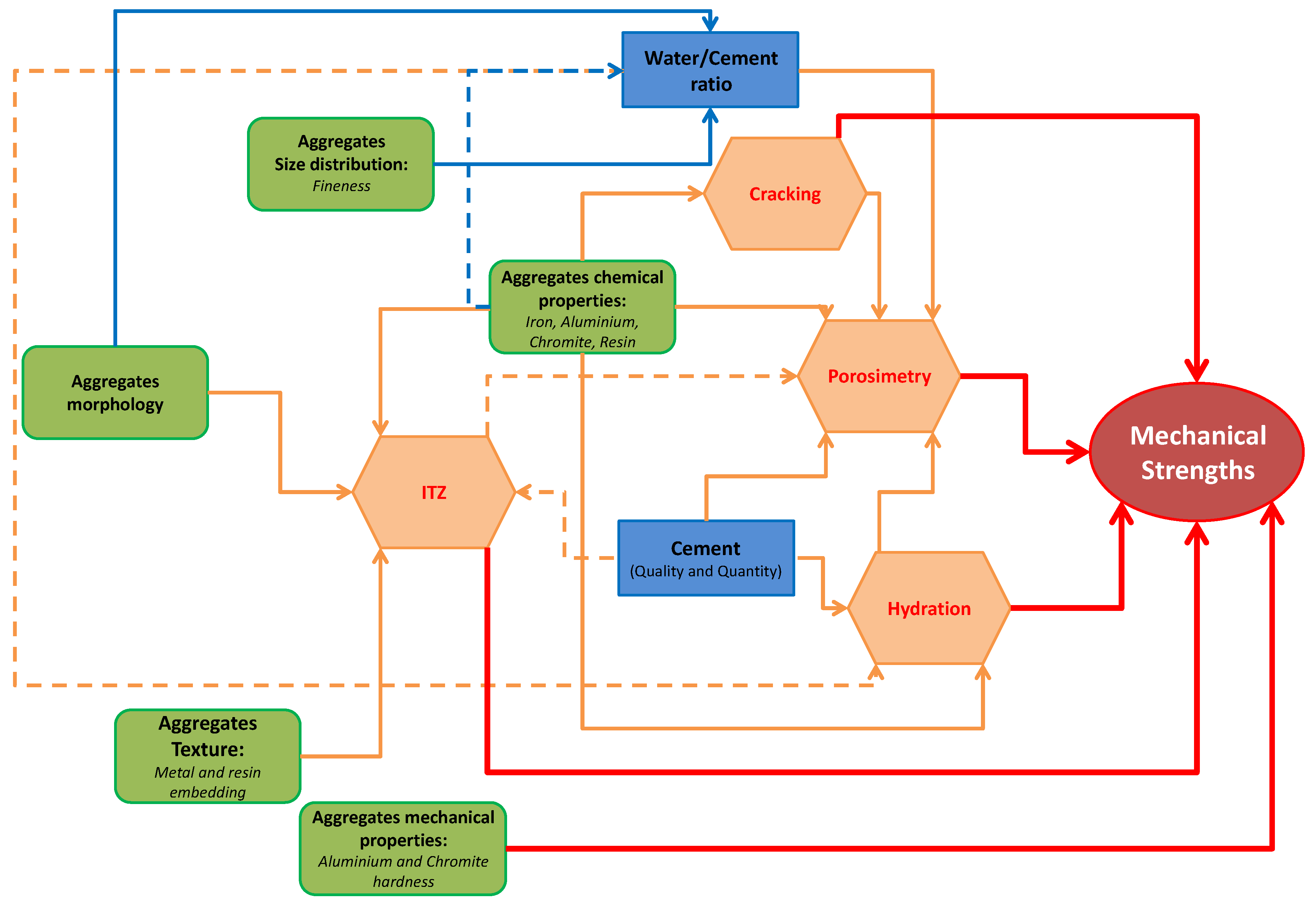
The different physicochemical parameters of the aggregates in connection with those of the other materials present in the concrete as well as the formulation of the cementitious materials influence the physicochemical properties of the latter and thus their mechanical properties. While being aware that it is not always easy to highlight the specific effects of the aggregates on the properties of the cementitious materials, an overview is provided in Figure 1 with an indication of the potential influential parameters of SCFS. The arrows are oriented from the potential influential parameters of the aggregates to the properties or parameters of the cementitious materials likely to be impacted.
The results of the literature reflect a great variability in the properties of used foundry sands due to the binder used, the metals cast and the casting and treatment processes. This variability emphasizes the importance of as complete as possible characterization of a used foundry sand before its recovery in concrete. This paper presents the results of an exhaustive physical and chemical characterization of a spent chemical foundry sand with an analysis of its suitability according to the standard for aggregates used in concrete NF EN 12620 + A1 [36]. Its morphology as well as its chemical and crystallographic composition, which can significantly impact the cementitious materials properties, are also determined. Particular attention is given to the quantification and qualification of metallic elements present in the sand. The influence of the by-product on the workability and mechanical strength of cementitious materials is highlighted by avoiding, in a first step, the possible effect of the coarse aggregates and working on mortars for different substitution rates (0, 10, 30, 50, 80, 100). Furthermore, the influence of the spent foundry sand on the compressive strength and workability of concrete is also determined at the substitution rate of 30%.
2. Materials and Methods
2.1. Materials
The spent chemical foundry sand was provided by a soil disposal firm. Originally used for various castings within an aerospace company, it was treated to reduce its phenol and heavy metal contents and to allow for its storage as an inert by-product. The results of the leaching tests carried out before the storage of this by-product showed a maximum phenol content of 0.1 mg/kg of sand in relation to the dry mass on the leachate, which makes it possible to consider its use in concrete [56].
The by-product mixed with various other elements of the storage site such as stones, screws and plastic waste was received in a big bag of about 1 m3 and stored outdoors. Homogenized laboratory samples of about 10 kg were prepared in a three-step procedure. First, a part of the spent foundry sand was taken from different parts of the big bag and then sun-dried in a dedicated container. After drying, various samples were taken from different places of the container in order to constitute the laboratory samples. These laboratory samples were sieved with a 2 mm aperture sieve in order to remove the stones and other debris and to work with a spent foundry sand belonging to the same particle size range as SS. The spent chemical foundry sand obtained after this procedure and characterized in this work will be called “SCFS” in the following.
The samples used for the characterization of the sands were obtained according to two methods based on the NF EN 932-2 standard [57]. For the first method, a test portion is obtained directly from the laboratory sample by homogenized sampling and quartering. This method was used to study the suitability of SCFS according to the recommended tests of the NF EN 12620 + A1 standard [36]. The results reported correspond to the averages obtained for three samples. For the second method, a sub-sample with a mass equivalent to 600 times the mass of the test portion is first obtained by homogenized sampling and then reduced by quartering to obtain the test portion. This procedure was used for characterization tests carried out in addition to those recommended by the standard NF EN 12620 + A1 [36] and requiring the use of lightweight test portions. SCFS was characterized in comparison to a standardized sand grading from 0 to 2 mm and designated as “SS” in the following document.
Six mortars were formulated according to the NF EN 196-1 standard [58] with 0, 10, 30, 50, 80 and 100% of the by-product and are designated respectively SM, FSM10, FSM30, FSM50 and FSM80. For each batch, 450 g of a cement CEM I 52,5 and 1350 g of sand were used. To obtain a standardized consistency for each mortar, the water/cement (w/c) ratio of 0.5 required for the standard mortar SM was adjusted for the SCFS-based mortars. The details of substitution of SCFS are presented in Table 1 as well as the fineness moduli of the sands or mixed sands used in each formulation and their W/C ratio. The modifications in the substitution grading ranges were done mainly to ensure to work with grading curves that better match that of SS, especially for the 30% substitution rate.
For the formulations of the concretes, the cement CEM I 52,5 was used with three natural siliceous aggregates: a concrete sand (CS) and two coarse aggregates (CA 4/8, CA 8/16). A concrete of S3 slump class and C 30/37 strength class was first formulated as reference concrete (RC) without SCFS, a cement content of 390 kg/m3 of concrete and ratios of 1; 1.89; 0.92; 1.80 and 0.53 for cement, sand, CA 4/8, CA 8/16 and water, respectively. For the SFCS-based concrete (FSC), the same ratios were applied for the cement, water, coarse aggregates and total mass of fine aggregates. Thirty percent of the CS particles ranging from 0 to 0.5 mm were replaced by SCFS particles belonging to the same grading range (Table 1).
2.2. Methods
2.2.1. Recommended Physical and Chemical Characterization of the Aggregates
The sieving tests were carried out according to the NF EN 933-1 standard [59] for sieve apertures of: 0.063–0.080–0.125–0.160–0.250–0.50–1–1.6–2 mm. The fines content was determined by washing with a 63 µm sieve, and the fineness modulus was also calculated in accordance with NF EN 12620 + A1 [36]. The fines quality was evaluated by the sand equivalent test according to the NF EN 933-8 + A1 standard [30], and the particle densities as well as the water absorption were determined as described in the NF EN 1097-6 standard [60].
The soluble elements content tests were performed according to the NF EN 1744-1 standard [61]. The content of water-soluble chloride salts was determined by the method based on Mohr described in Section 2 of the standard. The principle consists of extracting the chloride ions present in a test portion with water and then titrating the chloride with a silver nitrate solution (AgNO3) using potassium chromate (K2CrO4) as an indicator. The test for the determination of acid soluble sulfate ions was carried out according to Section 3 of the standard. The principle consists in extracting the sulphate ions present in the sand thanks to a diluted hydrochloric acid (HCl) solution and then precipitating them in the presence of a barium chloride solution (BaCl2). The sulfate ions content (SO3 or SO4) is then determined gravimetrically and expressed as a percentage by mass of the sand. Other sulfur compounds present in the aggregates can also produce sulfates when oxidized in the concrete. The test for total sulfur content was carried out by means of acid attack according to the method described in Section 3 of the standard. The principle is to oxidize all sulfur compounds present in the sand to sulfate oxides by treating a test sample with hydrogen peroxide and hydrochloric acid. The sulfate ions are then identified by adding a few drops of barium chloride to form a white precipitate of barium sulfate BaSO4. The importance of humus and fulvo acids contents was analyzed in a qualitative way according to Section 3 of the standard.
In order to understand the influence of SCFS better highlighted in the mortars, the by-product was comprehensively characterized by all the tests previously cited and in comparison to the natural sand SS used in SM. The natural suitable aggregates (CS, CA 4/8 and C 8/16) used in the concretes were only characterized according to the tests necessary for the formulation of the cementitious materials: the sieving test as well as the particle density and water absorption tests.
2.2.2. Chemical and Crystallographic Composition of the Mortars Aggregates
The chemical compositions of SS and SCFS were determined by X-ray fluorescence after determination of the loss on ignition at 1000 °C. The samples were obtained by the second reduction procedure and then ground to 80 µm. The analyses were performed using the Bruker S4 Explorer wavelength dispersive spectrometer, and the results are given as oxides with an accuracy of 0.1%. The crystallographic compositions of SS and SCFS were also determined by X-ray diffraction (XRD) on powder after grinding and sieving at 80 µm. The equipment used was the D8 Advance diffractometer from the Bruker group with copper radiation (Cu Kα, λ = 1.54506 Å). Three samples were tested for each sand, and the results obtained were evaluated using the Diffrac EVA® software. These two chemical and crystallographic characterization tests were coupled with scanning electron microscopy (SEM) under high vacuum for a pressure below 4 × 20−5 mbar. The sand particles were coated in resin and then polished for a better chemical characterization with a backscattered electron detector (BSE). The apparatus used is a Philips XL30 ESEM equipped with a tungsten filament electron gun and associated with an energy dispersive spectroscopy module (SEM–EDS).
2.2.3. Morphology and Embedding of the Mortar Aggregates
Other observations were made using SEM with a BSE detector (SEM–BSE) to characterize the morphology of the coated grains. Some uncoated SCFS grains were also analyzed. They were attached to a carbon band and studied directly after being metallized by a gold flash. No coating or polishing was applied in order to allow characterization of the shape of the grains over almost their entire volume. Optical microscopic observations were carried out additionally for a better appreciation of the differences in shades which can make it possible to distinguish possible elements present notably in embedding of the grains.
2.2.4. Metallic Particles Characterization of the Spent Foundry Sand
A methodology was developed for the physical and chemical characterization of metallic particles or sand grains aggregated with metallic particles present in SCFS. It consists in separating these particular elements from all the grains composing a given sample, quantifying their percentage by mass difference and determining their particle size distribution as well as the different morphologies and chemical compositions they may have. As the spent foundry sands contain metallic elements coming mainly from iron alloys, the separation of the metallic elements was performed by magnetization.
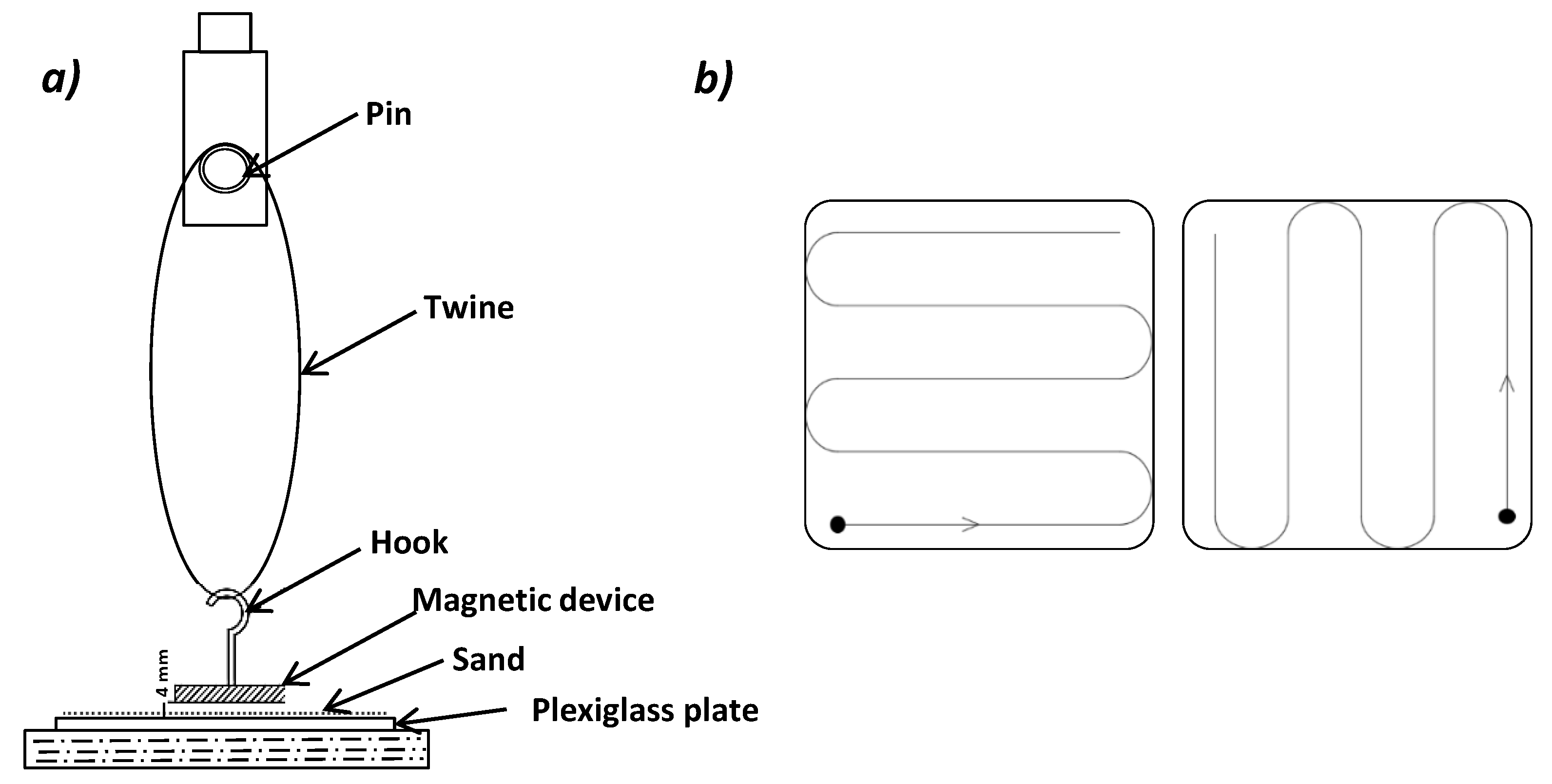
The physical separation and quantification procedure was performed on a 20 g test portion per unit test on ten individual test specimens of about 2 g. The test portion was obtained by the second reduction procedure, and the separation of the magnetizable particles was carried out according to the schematic illustration presented Figure 2. The separation was carried out for each test specimen of about 2 g by arranging the SCFS specimen in a thin layer distributed on a plexiglass plate and holding a magnet wrapped in aluminum foil above. The magnetic device was kept at a distance of 4 mm for all tests in order to not change the magnetization property. The plexiglass plate was moved under the magnet to cover the entire surface of the test specimen. The magnetization pattern is provided in Figure 2b. The magnetized particles were regularly removed from the surface of the foil and stored in a previously weighed container. Magnetization was considered complete when, after several successive passes of the magnetic device over the reshuffled SCFS test specimen, no additional particles were magnetically attracted.
The total quantification of the magnetizable particles contained in the test portion was obtained by summing the masses of magnetizable particles for each test specimen of about 2 g and expressing this sum as a percentage of the initial mass of the test portion (20 g).
The size of these particles was determined by direct measurement. For each 2 g specimen, the retained magnetized particles were observed under a digital optical microscope, and a statistical measurement of their size was performed. The dimension was determined on the diagonal of 200 particles per test specimen, which means a total of 2000 measurements for the 20 g test portion. Studies of the morphology and the chemistry of the particles were also completed through the optical and electronic microscopic observations, as described previously.
2.2.5. Rheological and Mechanical Properties of Mortars and Concretes
The workability of the cementitious materials were characterized by the standardized consistency test NF EN 413-2 [62] for the mortars and the standardized slump test NF EN 12350-2 [63] for the concretes. The mechanical strengths tests were carried out at 28 days. The mortars were tested in accordance with the NF EN 196-1 standard [58] with a loading rate of 50 N/s in flexion and 2400 N/s in compression. The three-point bending tests were performed on three prismatic specimens of dimensions 40 × 20 × 260 mm3 and the compression tests on six half-prisms. The concretes were tested in compression with a hydraulic machine of a capacity of 5000 kN at a rate of 10 kN/s. Three 15 cm × 15 cm × 15 cm cubic specimens were solicited per formulation.
3. Results
3.1. Recommended Physical and Chemical Characterization of the Aggregates
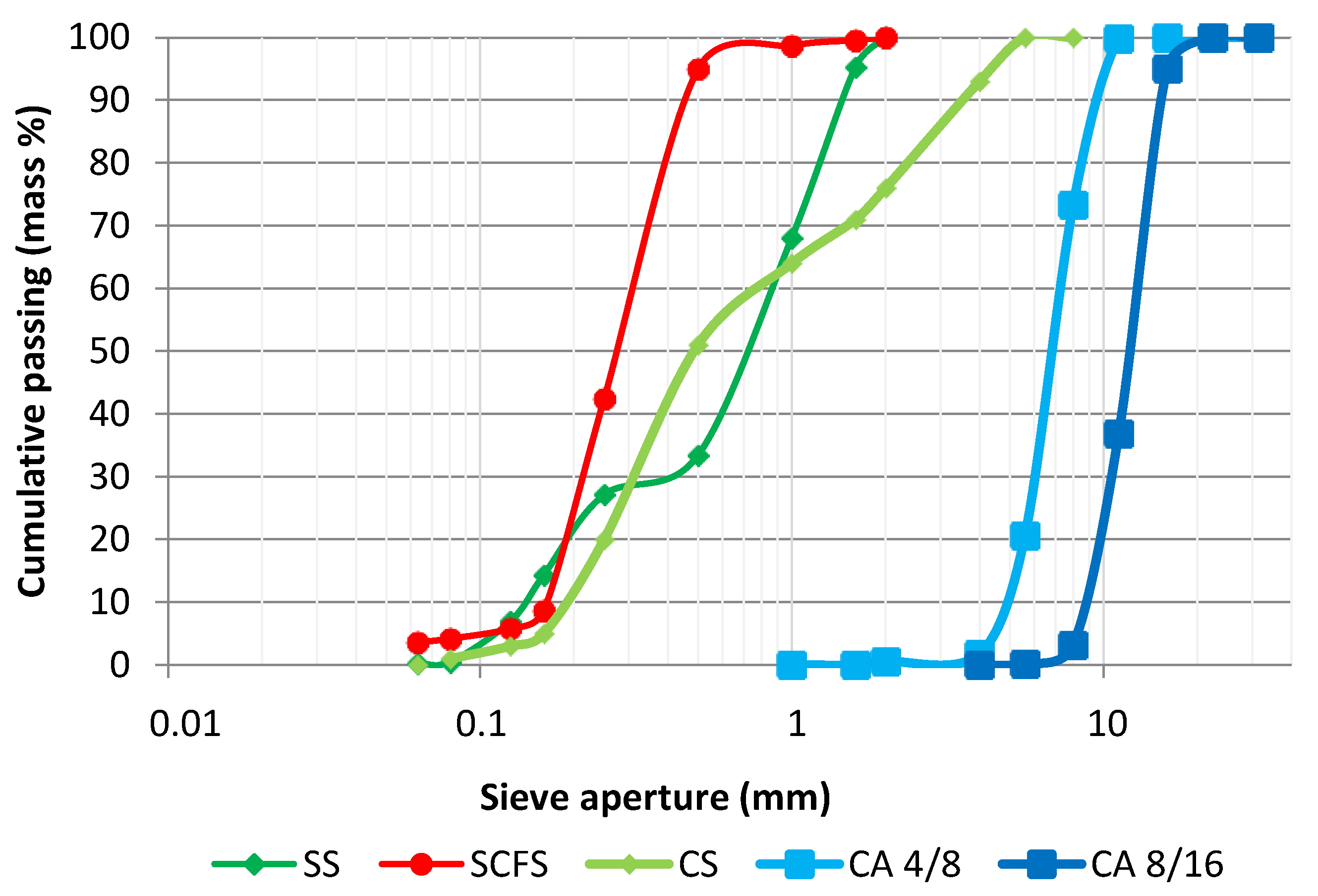
The results of the sieving tests are given in the form of grading curves in Figure 3. The natural aggregates CS, CA 4/8 and CA 8/16 used in the concretes are, respectively, in the grading ranges of 0 to 4 mm, 4 to 8 mm and 8 to 16 mm, whereas SS ranges from 0 to 2 mm and SCFS more between 0 to 0.5 mm. Compared to CS and SS, SCFS is more uniform and presents a greater fineness, with 95% of its particles having a diameter of less than 500 µm compared to 51% for CS and 32% for SS.
The particle density, water co-efficient absorption, fineness modulus and fines content are given in Table 2. for all five aggregates. The fineness modulus results confirm the greater fineness of SCFS. A slight increase ranging from 2 to 5% is observed in the particle density of SCFS in comparison with those of the natural aggregates. The water absorption also increases for SCFS in comparison with SS, but this has insignificant impact on the effective w/c calculation. Moreover, the water absorption of the by-product is less important than that of the natural aggregates used in the concretes. The fines content, insignificant for all the natural aggregates, corresponds, for SCFS, to the limit from which it cannot be considered non-harmful to concrete by the standard NF EN 12620 + A1 [36] if it is used in full substitution of natural fine aggregates. The SE results showed a very high degree of cleanliness for the by-product (92 ± 1%) regarding clay fines and equivalent to the results obtained for SS (95 ± 1%).
Water-soluble chloride ion contents were found to be 0.00% for both sands. In the tests for acid-soluble sulfate ions and total sulfur, the addition of barium chloride to the extracted solution of the different sands did not result in any barium sulfate precipitate. These observations led to the conclusion that there were no sulfur compounds in the different sands studied. The different qualification tests of humus and fulvo acid content gave negative results for both sands. The possible dissolved organic components were not in sufficient quantities to induce the required coloration to qualify their contents as critical for the hydration of cementitious materials.
3.2. Chemical and Crystallographic Composition of the Mortars Aggregates
The main chemical components of the sands and their loss on ignition (LOI) values are presented in Table 3. The LOI value of 1.6% for SCFS is higher than that of SS (0.3%) but still remains fairly low. Both sands are mainly composed of silica, whose content is higher for SS (97.7%) than for SCFS (84.0%). The elements chromium (Cr), iron (Fe) and aluminum (Al), which are absent or in low amounts in SS, are present in significant quantities in the by-product.
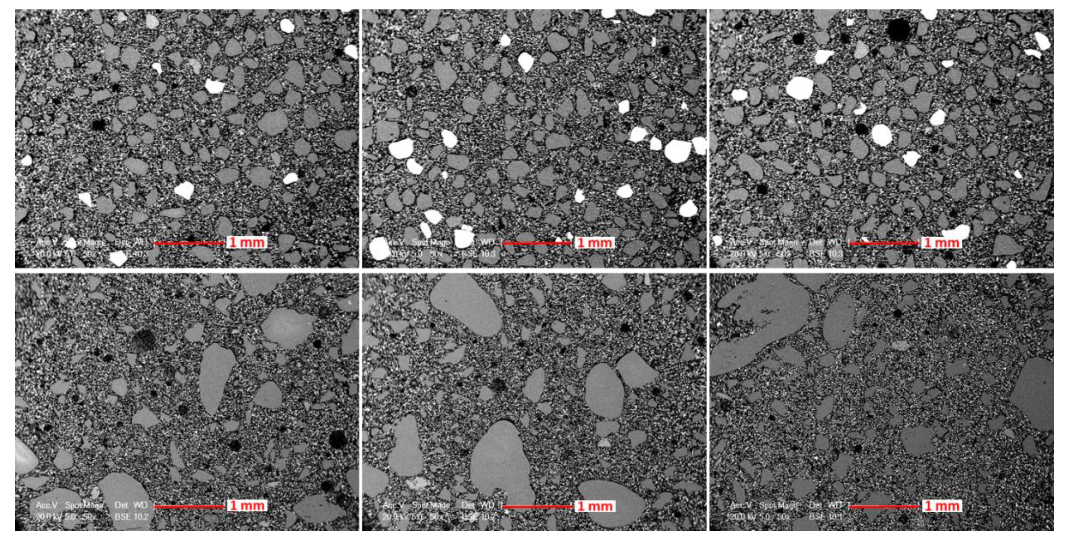
SEM observations with BSE detector on embedded SCFS particles also indicate the presence of a majority of silica as well as other elements with a higher atomic weight. Different images assembled Figure 4 give an idea of the proportion of these heavier particles (white) compared to the silica particles (grey). It also highlights the fineness and uniformity of the SCFS grain sizes as well as their pre-dominantly sub-angular and sometimes round shapes.
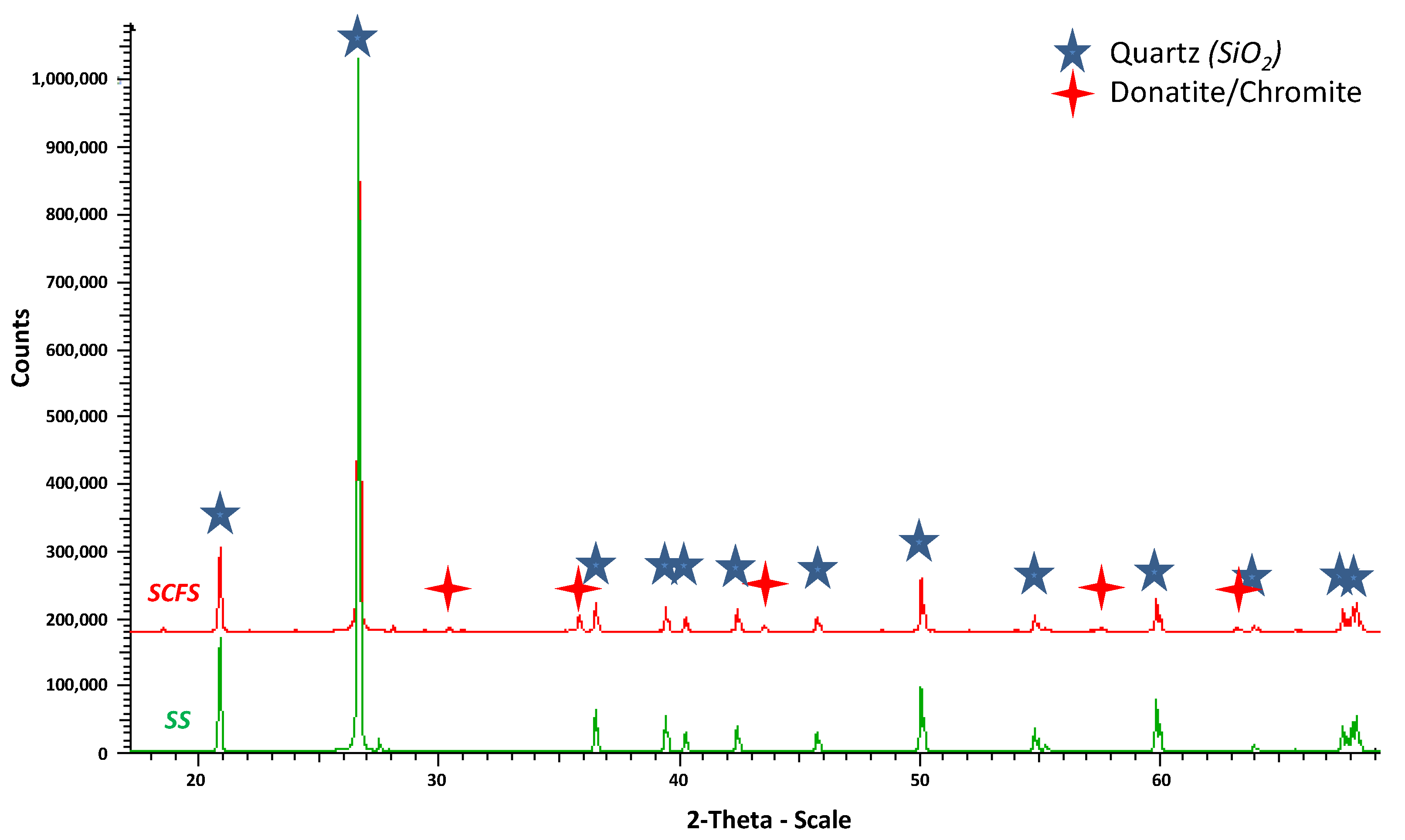
The crystallographic composition of the sands determined by X-ray diffraction confirms that the main element of the sands is silica present as quartz. Figure 5 shows examples of diffractograms for the two sands. It highlights the quartz peaks as well as other less important peaks for SCFS, which are characteristics of other secondary mineral phases. One of the phases identified is donatite, also called chromite, which is mainly composed of chromium but also contains iron and sometimes traces of aluminum and magnesium.
3.3. Morphology and Embedding of the Mortars Aggregates
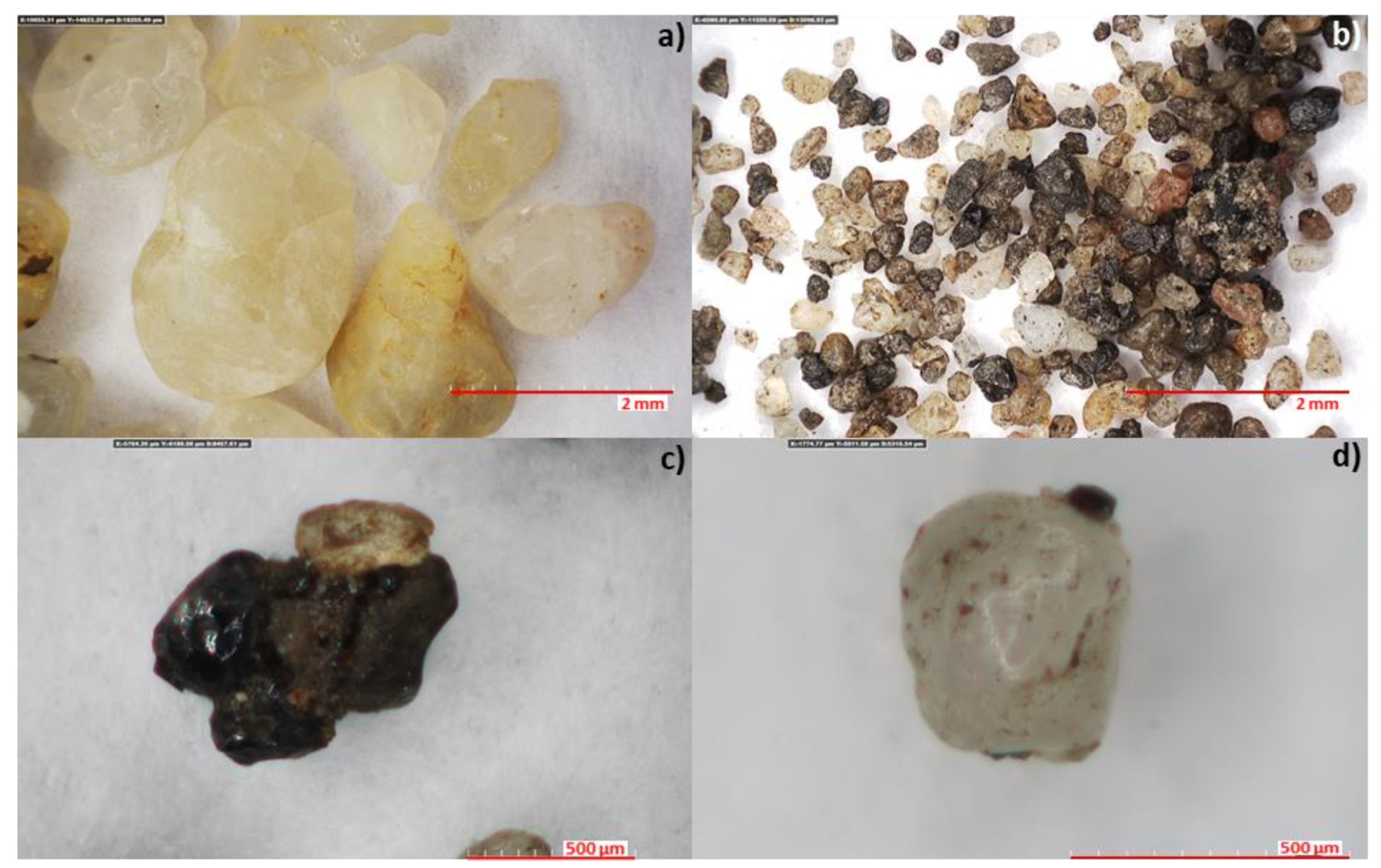
The digital microscope observations confirmed the different morphologies of SCFS and SS (Figure 6). The different shades of beige and yellow usually found in siliceous sands were observed for some particles. Other SCFS grains show a darker color (Figure 6c) which may be due to the presence of thermally degraded phenolic resin residues. Some particles may also be aggregated, as shown in Figure 6d.
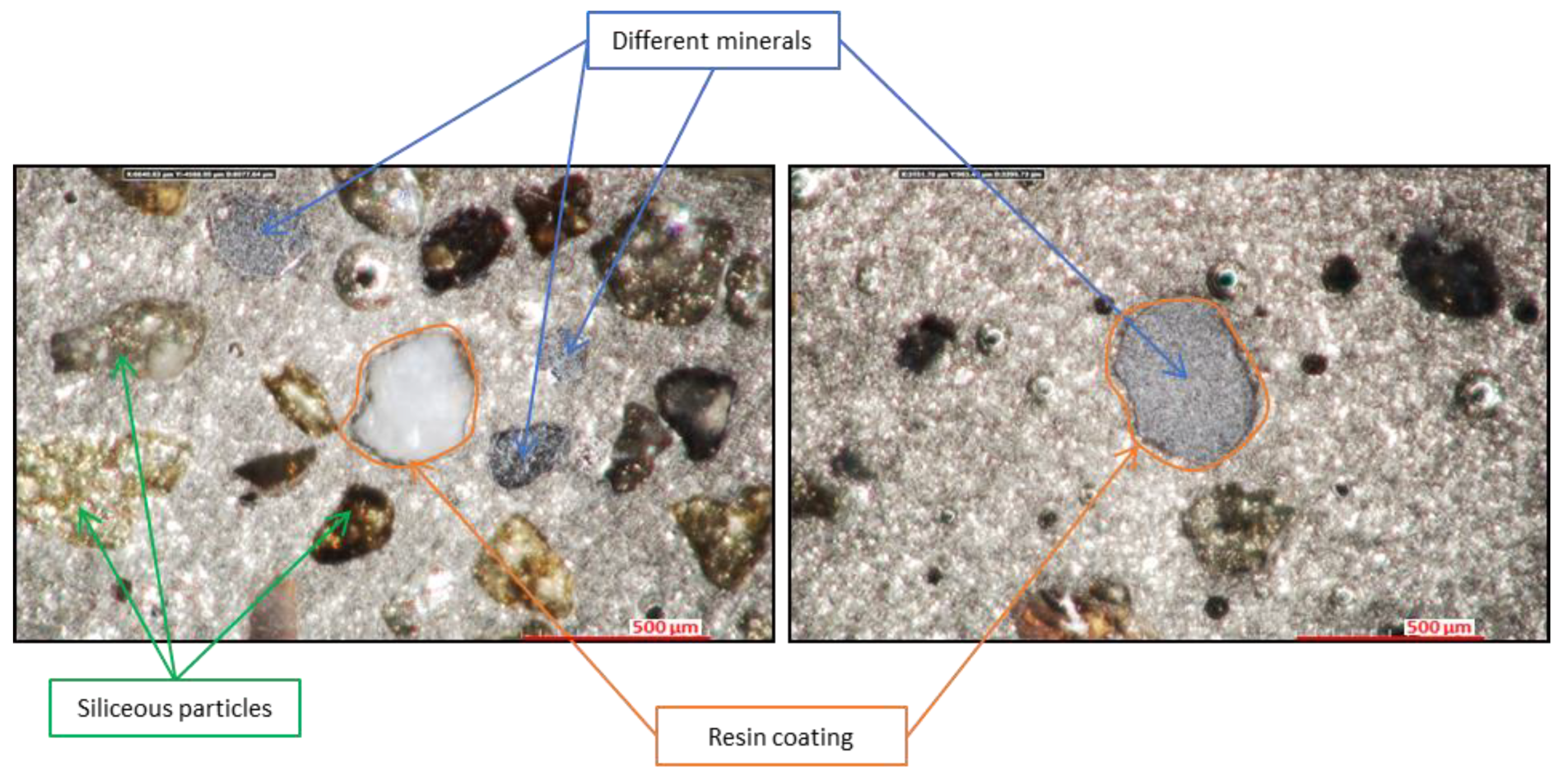
Additional observations on coated sand particles confirmed the presence of black degraded chemical resin residues around some spent foundry sand particles (Figure 7). They also highlighted the presence of some metallic grey colored particles.
3.4. Metallic Particles Characterization of the Spent Foundry Sand
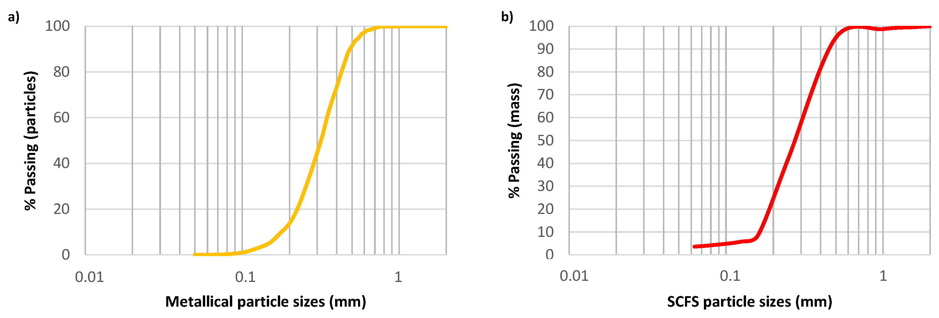
The magnetic separation of some SCFS metallic particles indicated that their mass percentage was 6.85% for the 20 g test portion. The average value is specifically 6.79 ± 0.95% for the 10 test specimens of about 2 g. The total mass of these particles corresponding to 1.4 g, a study of the particle size by the traditional sieving method is difficult to achieve. This explains the methodology developed with the digital microscope. The particle size distribution obtained for these magnetized particles is presented in Figure 8a. The results obtained by the sieving method for SCFS are also recalled in Figure 8b. A difference between the two curves can be observed at the beginning because the measured magnetized particles do not have any grains smaller than 150 µm, whereas they represent 6% by mass of the SCFS particles. However, the two curves show a similar particle size distribution thereafter. The particles smaller than 500 µm, which represent 95% of the mass of SCFS, account for 90% of all magnetized particles measured.
The observation of these magnetized particles with a digital microscope and an SEM with BSE detector highlighted that the magnetized particles can present similar shapes to those observed for SS and SCFS taken as a whole. It was also noted the presence of resin residues on the surface of the grains and the aggregation of various particles together.
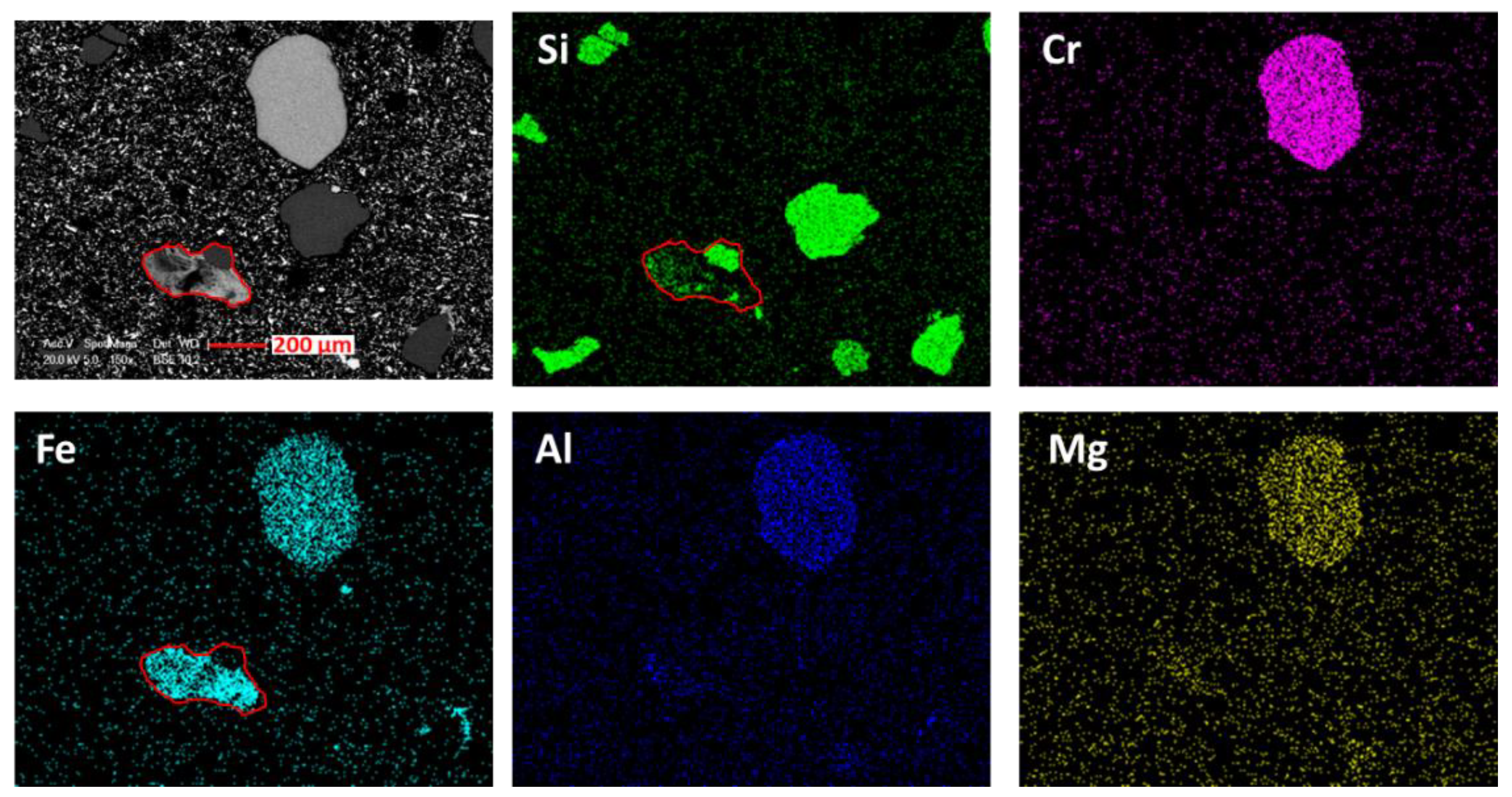
Several mappings carried out on some coated and polished magnetized particles confirmed the presence of silica as well as other metallic elements present in the form of composites. Figure 9 shows an example of mappings with a grain composed of a mixture containing mostly chromium, then iron, aluminum and magnesium. This type of particle, frequently found, is associated with chromite identified by XRD. On this same figure, the possibility of aggregation of silica grains and iron particle from the metal casting is highlighted (red outline).
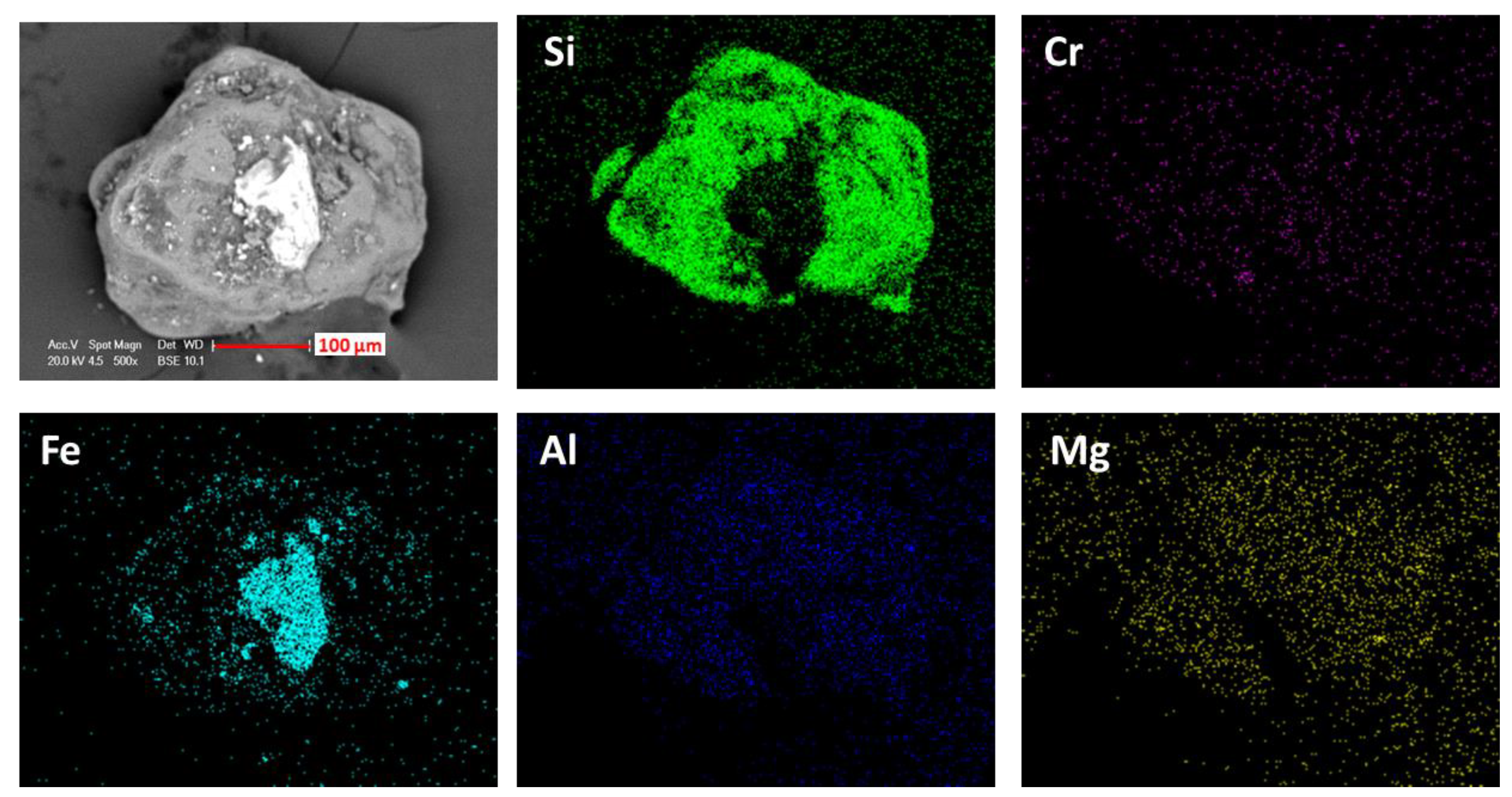
Observations and mapping on uncoated grains have verified this possibility of the presence of metallic particles aggregated on silica particles or of an aggregation of different silica particles together. Figure 10 illustrates an example of an aggregation of small iron particles on a silica grain.
3.5. Rheological and Mechanical Properties of Mortars and Concretes
The workability and mechanical strength results are presented in Table 4 along with two properties of the various mortars and concrete formulations. The results obtained for the SCFS-based mortars show that increasing the amount of by-product leads to a decrease in workability associated to a decrease of the fineness modulus as well as an increase of the w/c ratio necessary to obtain a standardized consistency. Compared to SS, the mixed sands offer better workability for the substitution rates up to 30% and worse workability for the substitution rates above 50%. The presence of SCFS leads to a decrease in the mechanical strengths of the mortars starting from the substitution rate of 10%. An accentuation in the loss ranges from 8% to 41% is also noted with the increase of the substitution rate.
When used in concrete, the influence of SCFS is attenuated compared to its influence in the mortars. In fact, whereas it is 8% for MSF10 formulated with 10% of SCFS, the loss recorded for FSC is only 4%, even if the substitution rate of 30% of CS by the by-product represents 12% of the total mass of fine and coarse aggregates. The variation observed for the concrete is only slightly larger than the standard deviation of measurement and similar to those reported by Mavroulidou and Lawrence, who also worked with a spent chemical foundry sand [13]. This reduction in the losses for the concrete can be explained by the difference in quality between CS and SS along with the presence of the coarse aggregates that also provide part of the strength of the concretes. The SCFS-based concrete presents a compressive strength that matches the requirements to correspond to the strength class C 30/37. This result shows that SCFS can be recovered in concretes at a substitution rate of 30% of the total fine aggregates and still allows the obtained cementitious materials to satisfy the normative minimum strength.
4. Discussions
4.1. Physical and Chemical Properties of the Aggregates
The sieving tests highlighted the uniform particle size distribution and fineness of SCFS as generally reported in the literature for spent foundry sands [7,10,15,16,17,18,19,20,21,22,23,24,25,26,27]. Its fines content determined by sieving at 63 µm is higher than that of SS and within the wide range of values found in the literature for elements with diameters below 75 µm [7,10,15,23,25,26,27,29]. This compliance with the literature values was also confirmed by the proportion of elements of diameter lower than 80 µm present in the by-product. Among the different criteria retained in NF EN 12620 + A1 to consider the presence of fines as non-harmful for concrete, the threshold value below which the fines present can be considered as non-harmful is 3%. Since the fines content of SCFS is equal to this threshold value, it does not allow classifying the fines present as non-harmful in the case of a complete substitution in the concrete. The sand equivalent test can also be used to estimate the harmfulness of the fines. It showed that, like SS, SCFS is very clean in terms of clay fines. Therefore, despite their 3% content, the fines present in SCFS can be classified as non-harmful according to the standard for concrete aggregates [36].
The determination of the water absorption demonstrated that the fines present in SCFS will have insignificant effect on the water demand of concrete. Indeed, even if this value is not equal to zero for the by-product as it is for SS, it remains fairly low and corresponds to the low part of the range of variation obtained for foundry sands in the literature [9,13,15,16,25,26,27,31,34,35]. It is even lower than some values obtained for natural sands [15,16,25,26,27,35]. This low value of water absorption may be due to the fact that the spent foundry sand studied in this work is a chemically bonded foundry sand and not a clay-bonded foundry sand.
The particle density of SCFS is consistent with that of spent chemical foundry sands characterized in the literature [10,13]. The slight increase observed in comparison to particle densities of the natural aggregates may be due to the presence of the metallic impurities or other minerals with higher densities than the siliceous particles.
Unlike the results obtained by Basar and Deveci Aksoy [31], water-soluble sulfur compounds and chlorides were absent or in quantities too small to be quantified by the tests performed on SS and SCFS. The same is true for humus or fulvo acid, which is consistent with the results of the previous authors [31]. The contents of these organic components are therefore not considered critical for the hydration of cementitious materials.
The complementary physicochemical characterization tests conducted showed that both sands were mainly composed of quartz. Iron, aluminum and chromium were also present in significant quantities in SCFS. The concentrations obtained for the first two are equivalent to those generally reported in the literature [7,16,37] and can be attributed to the casting of iron and aluminum alloys in the molds. The presence of chromium in a higher proportion than iron (3.6%) indicates that it does not only result from the casting of stainless steel but also from other minerals. The presence of chromite, occasionally used in foundries as a replacement for siliceous sand or in the production of chromium, was confirmed by XRD and SEM–EDS analyses. With the hardness of aluminum and chromite being of 5 to 6 on the Mohs scale and therefore lower than that of silica (7), the question arises as to their influence on the mechanical resistance of cementitious materials.
The microscopic observations also revealed differences in the color of some SCFS grains associated with their different crystallographic composition or by their embedding by thermally degraded resin during the casting of the metals. The presence of these resin residues also favors the aggregation of certain particles after the casting of the metals. The quantification of the metallic elements revealed a significant proportion of particles containing magnetic iron or particles bonded to magnetic iron. Their morphology characterization confirmed the grains aggregations, especially with metals. Their particle size distribution, similar to that of SCFS, from 150 µm, does not allow a treatment of the by-product by simple sieving. The question of the effect of these ferrous elements on the mechanical strength of concrete can be addressed, as the presence of iron in concrete has been linked to a modification of the hydration of the cementitious materials [55] or the quality of the ITZ around some ferrous particles [53,54].
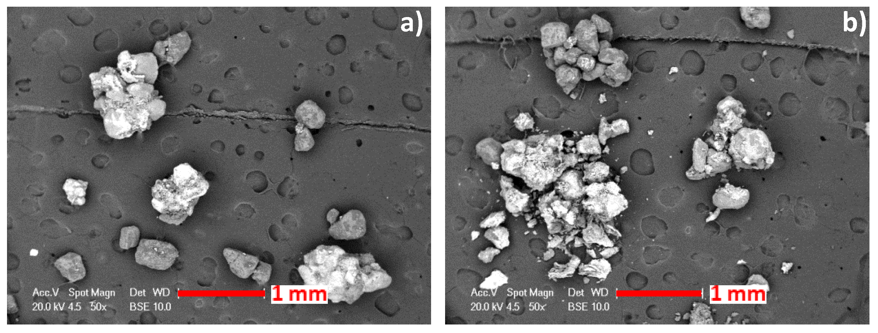
The observation of the various magnetic particles also led to the conclusion that, during the mixing of cementitious materials, a modification of the grain size of the sands is to be considered because certain aggregated grains present a weak bond between them. This modification of the particle size distribution can lead to a loss or gain of mechanical strengths depending on whether it involves a higher water demand [15,31,34,44] or a filler effect [20,25,26,42].
4.2. Workability and Mechanical Strengths of the Cementitious Materials
Similarly to two other studies found in the literature [34,64], the alteration in the workability observed for the mortars with substitution rates higher than 50% is associated to the greater fineness of the by-product, which results, for FSM80 and FSM100, in mixed sands with lower fineness moduli than that of SS. As for the improved workability of FSC in comparison to that of RC formulated with the same w/c ratio and a sand of the same fineness modulus, it can be attributed to a difference on the morphology and the texture of CS and SCFS.
The mechanical strengths loss was observed with the increase of the substitution rate of the SCFS-based mortars, since the substitution ration of 10% corresponds to the trends observed by five authors who worked on mortars and concretes for substitution rates of natural sands ranging from 10% to 100% and representing between 3% and 49% of the total mass of aggregates [15,31,34,35,45]. Nevertheless, it differs with other results showing an accentuation of the gains in concrete strengths with the increase of the substitution rate [20,25]. These variations, along with the differences observed in the work of Monosi et al. [15], for two spent foundry sands, highlight the importance of the physical and chemical properties of the waste foundry sands and their effect on the properties of the cementitious materials. The variability of the spent foundry sands found in the literature, the differences between the formulations and the scarcity of work realized on mortars or with comprehensively characterized spent foundry sands make it difficult to carry out an exhaustive analysis of the results obtained for mortars in comparison with those of the literature.
Regarding the effect of the potential influential parameters of the spent foundry sand studied in this work, the accentuation in the strength losses of the SCFS-based mortars can find an explanation in the fineness of the by-product and the increase in the water demand of the cementitious materials. However, the losses observed for the mortars formulated with 10% and 30% of SCFS do not result from the greater fineness of the by-product and higher w/c ratios. This means that other parameters such as the chemical impurities (phenolic resin residues, metallic elements, etc.), which can also alter the mechanical properties of cementitious materials, are to be taken into account. Incorporated with the by-product, their increase with the substitution rate of SCFS can result, for some of them, in an increase of the porosity of the cementitious materials [46,47,48,49]. Furthermore, the lowest hardness (5 to 6 on the Mohs scale) of some metallic elements such as iron, aluminum or chromium, in comparison to silica (7), could also lead to a decrease in the mechanical strengths of cementitious materials.
5. Conclusions
This work aimed to exhaustively characterize a spent chemical foundry sand for its recovery in concrete and to investigate its influence on the workability and mechanical strengths of cementitious materials. The methodology developed to characterize the by-product can serve as a guidance for future works on other spent foundry sands. The tests performed to characterize the morphology of the by-product and to determine its chemical and crystallographic compositions revealed the presence of some impurities. In the form of a metal–silica aggregation, minerals essentially based on chromium and iron, or residues of degraded resin coating the particles, are possible causes of modification of the porosimetry, hydration and mechanical resistances of the cementitious materials. The various standardized physical and chemical characterization tests performed on the by-product have determined that, even if caution must be taken regarding its fineness, which can modify the workability and mechanical properties of cementitious materials, it is still suitable for use in concrete. Moreover, a formulation of concrete compatible for pre-cast and that matches the C 30/37 strength class is proposed with a substitution of 30% of the natural fine aggregate by the spent foundry sand.
To go further in the study of the recovery of spent foundry sands in concretes, works of characterization of porosimetry, hydration and micro-structure of cementitious materials formulated with these by-products should be carried out in addition to those relating to their effect on the mechanical resistances. Considering that these by-products are available in significant quantities and are not yet widely recovered, these additional studies would help improve the understanding on their effects on the concretes properties for a better recovery in these building materials which would of great benefit from both economic and environmental aspects.
Author Contributions
Conceptualization, F.F.; methodology, P.P.; validation, P.P.; investigation, P.P. and C.D.; resources, F.F. and E.B.; data curation, P.P.; writing—original draft preparation, P.P.; writing—review and editing, E.B., C.D. and K.L.A.; visualization, P.P.; supervision, F.F.; project administration, E.B. and P.P.; funding acquisition, E.B. All authors have read and agreed to the published version of the manuscript.
Funding
This research and the APC were funded by INSA de Strasbourg.
Acknowledgments
The authors would like to thank INSA de Strasbourg who provided the funds for this research and the APC.
Conflicts of Interest
The authors declare no conflict of interest. The funders had no role in the design of the study; in the collection, analyses, or interpretation of data; in the writing of the manuscript; nor in the decision to publish the results.
References
- Jasson, P. Sables et Matériaux de Moulage de Fonderie; Editions T.I.: Saint-Denis, France, 1999; pp. 2–23. [Google Scholar]
- Hackney, P.; Wooldridge, R. Optimisation of Additive Manufactured Sand Printed Mould Material for Aluminium Castings. Procedia Manuf. 2017, 11, 457–465. [Google Scholar] [CrossRef]
- Trinowski, D.M. Foundry. In Phenolic Resins: A Century of Progress; Pilato, L., Ed.; Springer: Berlin/Heidelberg, Germany, 2010; pp. 451–502. [Google Scholar] [CrossRef]
- Siddique, R.; Kaur, G.; Rajor, A. Waste foundry sand and its leachate characteristics. Resour. Conserv. Recycl. 2010, 54, 1027–1036. [Google Scholar] [CrossRef]
- Devaux, P.; Vecoven, J. Les dechets de sables de fonderie en technique routiere. Bull. Int. Assoc. Eng. Geol. 1984, 30, 375–378. [Google Scholar] [CrossRef]
- Siddique, R. Foundry Sand. In Waste Materials and By-Products in Concrete; Springer: Berlin/ Heidelberg, Germany, 2008; pp. 381–406. Available online: https://www.springer.com/gp/book/9783540742937 (accessed on 15 October 2021).
- Guney, Y.; Sari, Y.D.; Yalcin, M.; Tuncan, A.; Donmez, S. Re-usage of waste foundry sand in high-strength concrete. Waste Manag. 2010, 30, 1705–1713. [Google Scholar] [CrossRef] [PubMed]
- Carnin, R.L.; Folgueras, M.V.; Luvizão, R.R.; Correia, S.L.; Da Cunha, C.J.; Dungan, R.S. Use of an integrated approach to characterize the physicochemical properties of foundry green sands. Thermochim. Acta 2012, 543, 150–155. [Google Scholar] [CrossRef]
- Deng, A.; Tikalsky, P.J. Geotechnical and leaching properties of flowable fill incorporating waste foundry sand. Waste Manag. 2008, 28, 2161–2170. [Google Scholar] [CrossRef] [PubMed] [Green Version]
- Iloh, P.; Fanourakis, G.; Ogra, A. Evaluation of Physical and Chemical Properties of South African Waste Foundry Sand (WFS) for Concrete Use. Sustainability 2019, 11, 193. [Google Scholar] [CrossRef] [Green Version]
- Javed, S.; Lovell, C.W.; Wood, L.E. Waste Foundry Sand in Asphalt Concrete; Transportation Research Board: Washington, DC, USA, 1994; no 1437; pp. 27–34. [Google Scholar]
- Javed, S. Use of Waste Foundry Sand in Highway Construction: Final Report; Purdue University: West Lafayette, IN, USA, 1994. [Google Scholar] [CrossRef] [Green Version]
- Mavroulidou, M.; Lawrence, D. Can waste foundry sand fully replace structural concrete sand? J. Mater. Cycles Waste Manag. 2018, 21, 594–605. [Google Scholar] [CrossRef] [Green Version]
- Monosi, S.; Sani, D.; Tittarelli, F. Used Foundry Sand in Cement Mortars and Concrete Production~!2010-03-27~!2010-05-03~!2010-07-07~! Open Waste Manag. J. 2010, 3, 18–25. [Google Scholar] [CrossRef]
- Monosi, S.; Tittarelli, F.; Giosuè, C.; Ruello, M.L. Effect of two different sources and washing treatment on the properties of UFS by-products for mortar and concrete production. Constr. Build. Mater. 2013, 44, 260–266. [Google Scholar] [CrossRef]
- Etxeberria, M.; Pacheco, C.; Meneses, J.; Berridi, I. Properties of concrete using metallurgical industrial by-products as aggregates. Constr. Build. Mater. 2010, 24, 1594–1600. [Google Scholar] [CrossRef]
- Yazoghli-Marzouk, O.; Vulcano-Greullet, N.; Cantegrit, L.; Friteyre, L.; Jullien, A. Recycling foundry sand in road construction–field assessment. Constr. Build. Mater. 2014, 61, 69–78. [Google Scholar] [CrossRef]
- Dayton, E.A.; Whitacre, S.D.; Dungan, R.S.; Basta, N.T. Characterization of physical and chemical properties of spent foundry sands pertinent to beneficial use in manufactured soils. Plant Soil 2009, 329, 27–33. [Google Scholar] [CrossRef]
- Aggarwal, Y.; Siddique, R. Microstructure and properties of concrete using bottom ash and waste foundry sand as partial replacement of fine aggregates. Constr. Build. Mater. 2014, 54, 210–223. [Google Scholar] [CrossRef] [Green Version]
- Gurumoorthy, N.; Arunachalam, K. Micro and mechanical behaviour of Treated Used Foundry Sand concrete. Constr. Build. Mater. 2016, 123, 184–190. [Google Scholar] [CrossRef]
- Kaur, G.; Siddique, R.; Rajor, A. Micro-structural and metal leachate analysis of concrete made with fungal treated waste foundry sand. Constr. Build. Mater. 2013, 38, 94–100. [Google Scholar] [CrossRef]
- Naik, T.R.; Kraus, R.N.; Ramme, B.W.; Canpolat, O. Effects of Fly Ash and Foundry Sand on Performance of Architectural Precast Concrete. J. Mater. Civ. Eng. 2012, 24, 851–859. [Google Scholar] [CrossRef]
- Naik, T.R.; Singh, S.S.; Ramme, B.W. Performance and Leaching Assessment of Flowable Slurry. J. Environ. Eng. 2001, 127, 359–368. [Google Scholar] [CrossRef]
- Siddique, R.; Aggarwal, Y.; Aggarwal, P.; Kadri, E.-H.; Bennacer, R. Strength, durability, and micro-structural properties of concrete made with used-foundry sand (UFS). Constr. Build. Mater. 2011, 25, 1916–1925. [Google Scholar] [CrossRef]
- Siddique, R.; de Schutter, G.; Noumowe, A. Effect of used-foundry sand on the mechanical properties of concrete. Constr. Build. Mater. 2009, 23, 976–980. [Google Scholar] [CrossRef]
- Singh, G.; Siddique, R. Effect of waste foundry sand (WFS) as partial replacement of sand on the strength, ultrasonic pulse velocity and permeability of concrete. Constr. Build. Mater. 2012, 26, 416–422. [Google Scholar] [CrossRef]
- Torres, A.; Bartlett, L.; Pilgrim, C. Effect of foundry waste on the mechanical properties of Portland Cement Concrete. Constr. Build. Mater. 2017, 135, 674–681. [Google Scholar] [CrossRef]
- Thaarrini, J.; Ramasamy, V. Properties of Foundry Sand, Ground Granulated Blast Furnace Slag and Bottom Ash Based Geopolymers under Ambient Conditions. Period. Polytech. Civ. Eng. 2016, 60, 159–168. [Google Scholar] [CrossRef]
- Prabhu, G.G.; Bang, J.W.; Lee, B.J.; Hyun, J.H.; Kim, Y.Y. Mechanical and Durability Properties of Concrete Made with Used Foundry Sand as Fine Aggregate. Adv. Mater. Sci. Eng. 2015, 2015, 1–11. [Google Scholar] [CrossRef] [Green Version]
- NF EN 933-8+A1, «Essais Pour Déterminer les Caractéristiques Géométriques des Granulats—Partie 8: Évaluation des Fines—Équivalent de Sable», AFNOR, Juill. 2015, [En Ligne]. Disponible Sur. Available online: https://viewer.afnor.org/Pdf/Viewer/?token=vCIm8Jr6ox81 (accessed on 15 October 2021).
- Basar, H.M.; Aksoy, N.D. The effect of waste foundry sand (WFS) as partial replacement of sand on the mechanical, leaching and micro-structural characteristics of ready-mixed concrete. Constr. Build. Mater. 2012, 35, 508–515. [Google Scholar] [CrossRef]
- Pasetto, M.; Baldo, N. Experimental analysis of hydraulically bound mixtures made with waste foundry sand and steel slag. Mater. Struct. 2014, 48, 2489–2503. [Google Scholar] [CrossRef]
- Rodríguez-Fernández, I.; Lastra-González, P.; Indacoechea-Vega, I.; Castro-Fresno, D. Recyclability potential of asphalt mixes containing reclaimed asphalt pavement and industrial by-products. Constr. Build. Mater. 2018, 195, 148–155. [Google Scholar] [CrossRef]
- Prabhu, G.G.; Hyun, J.H.; Kim, Y.Y. Effects of foundry sand as a fine aggregate in concrete production. Constr. Build. Mater. 2014, 70, 514–521. [Google Scholar] [CrossRef]
- Şahmaran, M.; Lachemi, M.; Erdem, T.; Yücel, H.E. Use of spent foundry sand and fly ash for the development of green self-consolidating concrete. Mater. Struct. 2010, 44, 1193–1204. [Google Scholar] [CrossRef] [Green Version]
- NF EN 12620+A1. Granulats Pour Béton; AFNOR: Paris, France, 2008; Available online: https://viewer.afnor.org/Pdf/Viewer/?token=DLfpPzofwEg1 (accessed on 15 October 2021).
- Alonso-Santurde, R.; Andrés, A.; Viguri, J.; Raimondo, M.; Guarini, G.; Zanelli, C.; Dondi, M. Technological behaviour and recycling potential of spent foundry sands in clay bricks. J. Environ. Manag. 2011, 92, 994–1002. [Google Scholar] [CrossRef] [PubMed]
- Arulrajah, A.; Yaghoubi, E.; Imteaz, M.; Horpibulsuk, S. Recycled waste foundry sand as a sustainable subgrade fill and pipe-bedding construction material: Engineering and environmental evaluation. Sustain. Cities Soc. 2017, 28, 343–349. [Google Scholar] [CrossRef]
- Pasetto, M.; Baldo, N. Recycling of waste aggregate in cement bound mixtures for road pavement bases and sub-bases. Constr. Build. Mater. 2016, 108, 112–118. [Google Scholar] [CrossRef]
- Quijorna, N.; Coz, A.; Andres, A.; Cheeseman, C. Recycling of Waelz slag and waste foundry sand in red clay bricks. Resour. Conserv. Recycl. 2012, 65, 1–10. [Google Scholar] [CrossRef]
- Hossiney, N.; Das, P.; Mohan, M.K.; George, J. In-plant production of bricks containing waste foundry sand—A study with Belgaum foundry industry. Case Stud. Constr. Mater. 2018, 9. [Google Scholar] [CrossRef]
- Siddique, R.; Singh, G.; Singh, M. Recycle option for metallurgical by-product (Spent Foundry Sand) in green concrete for sustainable construction. J. Clean. Prod. 2017, 172, 1111–1120. [Google Scholar] [CrossRef]
- Siddique, R.; Singh, G.; Belarbi, R.; Ait-Mokhtar, K. Kunal Comparative investigation on the influence of spent foundry sand as partial replacement of fine aggregates on the properties of two grades of concrete. Constr. Build. Mater. 2015, 83, 216–222. [Google Scholar] [CrossRef]
- Coppio, G.; de Lima, M.G.; Lencioni, J.W.; Cividanes, L.; Dyer, P.; Silva, S.A. Surface electrical resistivity and compressive strength of concrete with the use of waste foundry sand as aggregate. Constr. Build. Mater. 2019, 212, 514–521. [Google Scholar] [CrossRef]
- Khatib, J.; Herki, B.; Kenai, S. Capillarity of concrete incorporating waste foundry sand. Constr. Build. Mater. 2013, 47, 867–871. [Google Scholar] [CrossRef]
- Vipulanandan, C.; Krishnan, S. XRD analysis and leachability of solidified phenol-cement mixtures. Cem. Concr. Res. 1993, 23, 792–802. [Google Scholar] [CrossRef]
- Vipulanandan, C.; Krishnan, S. Solidification/stabilization of phenolic waste with cementitious and polymeric materials. J. Hazard. Mater. 1990, 24, 123–136. [Google Scholar] [CrossRef]
- Mueller, U.; Rübner, K. The microstructure of concrete made with municipal waste incinerator bottom ash as an aggregate component. Cem. Concr. Res. 2006, 36, 1434–1443. [Google Scholar] [CrossRef]
- Aubert, J.; Husson, B.; Vaquier, A. Metallic aluminum in MSWI fly ash: Quantification and influence on the properties of cement-based products. Waste Manag. 2004, 24, 589–596. [Google Scholar] [CrossRef]
- Murat, M.; Sorrentino, F. Effect of large additions of Cd, Pb, Cr, Zn, to cement raw meal on the composition and the properties of the clinker and the cement. Cem. Concr. Res. 1996, 26, 377–385. [Google Scholar] [CrossRef]
- Maaouia, O.B. Aptitude des Granulats Issus des Bétons de Déconstruction à la Réutilisation, Vis-à-Vis du CrVI: Impact des Propriétés de la Matrice Cimentaire et Identification des Mécanismes de Relargage; Université Paris-Est: Paris, France, 2018; [En ligne]; Available online: https://tel.archives-ouvertes.fr/tel-02469324 (accessed on 15 October 2021).
- Macphee, D.; Glasser, F. Immobilization Science of Cement Systems. MRS Bull. 1993, 18, 66–71. [Google Scholar] [CrossRef]
- Spitz, N.; Coniglio, N.; El Mansori, M.; Montagne, A.; Mezghani, S. Quantitative and representative adherence assessment of coated and uncoated concrete-formwork. Surf. Coatings Technol. 2018, 352, 247–256. [Google Scholar] [CrossRef] [Green Version]
- Santamaría, A.; Orbe, A.; Losañez, M.; Skaf, M.; Ortega-López, V.; Gonzalez, J.J. Self-compacting concrete incorporating electric arc-furnace steelmaking slag as aggregate. Mater. Des. 2017, 115, 179–193. [Google Scholar] [CrossRef]
- Rashad, A.M. A synopsis about the effect of nano-Al2O3, nano-Fe2O3, nano-Fe3O4 and nano-clay on some properties of cementitious materials—A short guide for Civil Engineer. Mater. Des. 2013, 52, 143–157. [Google Scholar] [CrossRef]
- Légifrance. Arrêté du 16 Juillet 1991 Relatif à L’élimination des Sables de Fonderie Contenant des Liants Organiques de Synthèse; Légifrance: Paris, France, 1991. [Google Scholar]
- NF EN 932-2. Essais Pour Déterminer les Propriétés Générales des Granulats—Partie 2: Méthodes de Réduction d’un Echantillon de Laboratoire; AFNOR: Paris, France, 1999; Available online: https://viewer.afnor.org/Pdf/Viewer/?token=ZS8wnhBcd_Q1 (accessed on 15 October 2021).
- NF EN 196-1. Méthodes D’essais des Ciments—Partie 1: Détermination des Résistances; AFNOR: Paris, France, 2016; Available online: https://viewer.afnor.org/Pdf/Viewer/?token=o9h6OdPwEMM1 (accessed on 15 October 2021).
- NF EN 933-1. Essais Pour Déterminer les Caractéristiques Géométriques des Granulats Partie 1: Détermination de la Granu-Larité—Analyse Granulométrique Par Tamisage; AFNOR: Paris, France, 2012; Available online: https://viewer.afnor.org/Pdf/Viewer/?token=OduB8wCu9l01 (accessed on 15 October 2021).
- NF EN 1097-6. Essais Pour Déterminer les Caractéristiques Mécaniques et Physiques des Granulats—Partie 6: Détermination de la Masse Volumique Réelle et du Coefficient D’absorption d’eau; AFNOR: Paris, France, 2014; Available online: https://viewer.afnor.org/Pdf/Viewer/?token=HWSlzIICfyM1 (accessed on 15 October 2021).
- NF EN 1744-1. Essais Visant à Déterminer les Propriétés Chimiques des Granulats—Partie 1: Analyse Chimique; AFNOR: Paris, France, 2014; Available online: https://viewer.afnor.org/Pdf/Viewer/?token=Pne3gdUdv041 (accessed on 15 October 2021).
- NF EN 413-2. Ciment à Maçonner—Partie 2: Méthodes D’essai; AFNOR: Paris, France, 2017; Available online: https://viewer.afnor.org/Pdf/Viewer/?token=KRF3wfrJQ7E1 (accessed on 15 October 2021).
- NF EN 12350-2. Essais Pour Béton Frais—Partie 2: Essai D’affaissement; AFNOR: Paris, France, 2012; Available online: https://viewer.afnor.org/Pdf/Viewer/?token=oP5JDhR7vxs1 (accessed on 15 October 2021).
- Khatib, J.M.; Baig, S.; Bougara, A.; Booth, C. Foundry sand utilisation in concrete production. In Proceedings of the Second International Conference on Sustainable Construction Materials and Technologies, Ancona, Italy, 28–30 June 2010. [Google Scholar]
Figure 1.
Overview of the different possible interactions between the influential parameters of concrete formulations (rectangles), the physicochemical (hexagons) and mechanical (bubble) properties of these cementitious materials.
Figure 1.
Overview of the different possible interactions between the influential parameters of concrete formulations (rectangles), the physicochemical (hexagons) and mechanical (bubble) properties of these cementitious materials.

Figure 2.
Schematic illustration of the magnetization procedure (a) and moving of the plate (b).

Figure 3.
Particle size distribution of SS and SCFS.

Figure 4.
SEM image (BSE detector) of SCFS (upper row) and SS (lower row).

Figure 5.
Diffractograms of SS and SCFS.

Figure 6.
Observation of sands under digital microscope: morphologies and colors of SS (a) and SCFS (b–d).
Figure 6.
Observation of sands under digital microscope: morphologies and colors of SS (a) and SCFS (b–d).

Figure 7.
Digital microscope observation of coated and polished SCFS particles.

Figure 8.
Particle size distribution of the magnetized particles of SCFS (a) and SCFS (b).

Figure 9.
SEM mappings of coated and polished SCFS magnetized particles: evidence of a chromite particle and an aggregation of iron and silica (in red).
Figure 9.
SEM mappings of coated and polished SCFS magnetized particles: evidence of a chromite particle and an aggregation of iron and silica (in red).

Figure 10.
SEM mappings of an uncoated foundry sand grain aggregated with iron.

Figure 11.
SEM observations of particles aggregations (a) and highlighting of the weakness of a bond (b).
Figure 11.
SEM observations of particles aggregations (a) and highlighting of the weakness of a bond (b).


Table 1.
Mortar and concrete formulations.
| SM | FSM10 | FSM30 | FSM50 | FSM80 | FSM100 | RC | FSC | |
|---|---|---|---|---|---|---|---|---|
| Substitution rate of the natural sands | 0% | 10% | 30% | 50% | 80% | 100% | 0% | 30% |
| SCFS 0/2 | / | / | / | / | / | 100% | / | / |
| SCFS 0/0.5 | / | 10% | 30% | 50% | 80% | / | 0% | 30% |
| CS 0/0.5 | / | / | / | / | / | / | 50% | 20% |
| CS 0.5/4 | / | / | / | / | / | / | 50% | 50% |
| W/C | 0.5 | 0.45 | 0.48 | 0.5 | 0.56 | 0.62 | 0.53 | 0.53 |
Table 2.
Physical characteristics and chemical composition of the aggregates.
| Oven-Dried Particle Density (t/m3) | Water Absorption (%) | Fineness Modulus | Fines Content (%) | |
|---|---|---|---|---|
| SS | 2.64 ± 0.01 | 0.07 ± 0.06 | 2.6 ± 0.0 | 0.0 ± 0.0 |
| SCFS | 2.69 ± 0.02 | 0.48 ± 0.14 | 1.6 ± 0.0 | 3.0 ± 0.1 |
| CS | 2.59 ± 0.02 | 1.05 ± 0.14 | 2.9 ± 0.0 | 0.3 ± 0.2 |
| CA 4/8 | 2.54 ± 0.01 | 1.67 ± 0.27 | 6.0 ± 0.0 | 0.1 ± 0.1 |
| CA 8/16 | 2.57 ± 0.00 | 1.25 ± 0.13 | 6.0 ± 0.0 | 0.0 ± 0.0 |
Table 3.
X-ray fluorescence (XRF) chemical composition of the sands (values in mass %).
| SS | SCFS | |
|---|---|---|
| SiO2 | 97.7 | 84.0 |
| Cr2O3 | 0.0 | 4.6 |
| Fe2O3 | 0.0 | 3.6 |
| Al2O3 | 0.7 | 3.1 |
| MgO | 0.0 | 0.7 |
| K2O | 0.2 | 0.4 |
| NiO | 0.3 | 0.3 |
| CaO | 0.1 | 0.3 |
| TiO2 | 0.0 | 0.1 |
| As2O3 | 0.0 | 0.1 |
| ZrO2 | 0.0 | 0.1 |
| LOI | 0.3 | 1.6 |
Table 4.
Workability, mechanical strengths and formulation properties of mortars and concretes.
| SM | FSM10 | FSM30 | FSM50 | FSM80 | FSM100 | RC | FSC | |
|---|---|---|---|---|---|---|---|---|
| Fineness modulus | 2.6 | 3.3 | 2.8 | 2.5 | 1.9 | 1.5 | 2.9 | 2.9 |
| w/c | 0.5 | 0.45 | 0.48 | 0.5 | 0.56 | 0.62 | 0.53 | 0.53 |
| Workability * (mm) | 7.0 ± 0.4 | 6.4 ± 0.6 | 5.5 ± 0.5 | 5.4 ± 0.1 | 4.8 ± 0.2 | 4.0 ± 0.9 | / | / |
| Rf (MPa) | 7.0 ± 0.4 | 6.4 ± 0.6 | 5.5 ± 0.5 | 5.4 ± 0.1 | 4.8 ± 0.2 | 4.1 ± 0.3 | / | / |
| Reduction in Rf compared to SM or RC | / | −8% | −21% | −23% | −31% | −41% | / | / |
| Rc (MPa) | 58.7 ± 1.4 | 54.5 ± 1.0 | 49.3 ± 1.0 | 42.6 ± 1.3 | 31.3 ± 1.9 | 26.0 ± 0.8 | 42.7 ± 0.2 | 40.8 ± 1.4 |
| Reduction in Rc compared to SM or RC | / | −7% | −16% | −27% | −47% | −56% | / | −4% |
* Consistency for mortars; slump for concretes.
Publisher’s Note: MDPI stays neutral with regard to jurisdictional claims in published maps and institutional affiliations. |
© 2021 by the authors. Licensee MDPI, Basel, Switzerland. This article is an open access article distributed under the terms and conditions of the Creative Commons Attribution (CC BY) license (https://creativecommons.org/licenses/by/4.0/).
Share and Cite
MDPI and ACS Style
Paul, P.; Belhaj, E.; Diliberto, C.; Apedo, K.L.; Feugeas, F. Comprehensive Characterization of Spent Chemical Foundry Sand for Use in Concrete. Sustainability 2021, 13, 12881. https://doi.org/10.3390/su132212881
AMA Style
Paul P, Belhaj E, Diliberto C, Apedo KL, Feugeas F. Comprehensive Characterization of Spent Chemical Foundry Sand for Use in Concrete. Sustainability. 2021; 13(22):12881. https://doi.org/10.3390/su132212881
Chicago/Turabian StylePaul, Paola, Essia Belhaj, Cécile Diliberto, Komla Lolonyo Apedo, and Françoise Feugeas. 2021. "Comprehensive Characterization of Spent Chemical Foundry Sand for Use in Concrete" Sustainability 13, no. 22: 12881. https://doi.org/10.3390/su132212881
Note that from the first issue of 2016, this journal uses article numbers instead of page numbers. See further details here.