
A Sine Cosine Algorithm-Based Fractional MPPT for Thermoelectric Generation System
by
 , and
, and
Hegazy Rezk
1,2,* ,
,
Mohammed Mazen Alhato
3,
Mujahed Al-Dhaifallah
4,5 and
Soufiene Bouallègue
3,6 1
College of Engineering at Wadi Addawaser, Prince Sattam Bin Abdulaziz University, Wadi Addawaser 11911, Saudi Arabia
2
Electrical Engineering Department, Faculty of Engineering, Minia University, Minia 61517, Egypt
3
Research Laboratory in Automatic Control (LARA), National Engineering School of Tunis, University of Tunis El Manar, Tunis 1002, Tunisia
4
Control and Instrumentation Engineering Department, King Fahd University of Petroleum & Minerals, Dhahran 31261, Saudi Arabia
5
Interdisciplinary Research Center (lRC) for Renewable Energy and Power Systems, King Fahd University of Petroleum & Minerals, Dhahran 31261, Saudi Arabia
6
High Institute of Industrial Systems of Gabès (ISSIG), University of Gabès, Gabès 6011, Tunisia
*
Author to whom correspondence should be addressed.
Sustainability 2021, 13(21), 11650; https://doi.org/10.3390/su132111650
Submission received: 28 August 2021
/
Revised: 16 October 2021
/
Accepted: 18 October 2021
/
Published: 21 October 2021
(This article belongs to the Special Issue Renewable and Sustainable Energy: Modeling, Control, Modern Optimization and Multi Criteria Decision Making)
Abstract
:Thermoelectric generators (TEGs) are equipment for transforming thermal power into electricity via the Seebeck effect. These modules have gained increasing interest in research fields related to sustainable energy. The harvested energy is mostly reliant on the differential temperature between the hot and cold areas of the TEGs. Hence, a reliable maximum power point tracker is necessary to operate TEGs too close to their maximum power point (MPP) under an operational and climate variation. In this paper, an optimized fractional incremental resistance tracker (OF-INRT) is suggested to enhance the output performance of a TEG. The introduced tracker is based on the fractional-order PIλDμ control concepts. The optimal parameters of the OF-INRT are determined using a population-based sine cosine algorithm (SCA). To confirm the optimality of the introduced SCA, experiments were conducted and the results compared with those of particle swarm optimization (PSO) and whale optimization algorithm (WOA) based techniques. The key goal of the suggested OF-INRT is to overcome the two main issues in conventional trackers, i.e., the slow dynamics of traditional incremental resistance trackers (INRT) and the high steady-state fluctuation around the MPP in the prevalent perturb and observe trackers (POTs). The main findings prove the superiority of the OF-INRT in comparison with the INRT and POT, for both dynamic and steady-state responses.
1. Introduction
In recent decades, thermal energy has become one of the renewable energies abundantly available in several industrial and civil sectors, namely, in powering electronic devices, driving electric vehicles, and in pumping applications [1,2]. Thermoelectric generators (TEGs), used in thermal energy conversion systems, are a type of active equipment that transform thermal power into electricity via the Seebeck effect [3,4]. These thermal devices have received increasing focus due to their capability to directly transform waste heat into electricity. Made up of different thermocouples, joined electrically in series and thermally in parallel, these heat modules are extensively utilized in various areas and domains, thanks to their attractive merits in terms of their power efficiency, the absence of moving parts and pollution, silent operation, free maintenance, and a long service life [1,2,5,6]. These thermal converters have gained increasing interest in the research fields concerned with their modeling, control, and optimization in various real-world applications. Therefore, characterized, maximum power point tracking (MPPT) approaches are mainly used to maximize the power harvested from TEG converters.
In all renewable energy converters, tracking the maximum power point (MPP) is vital to extracting the most power under varying environmental conditions. Various studies from the literature have reported on the MPPT control design and the implementation of TEG systems. The authors of [7] combined a TEG device with a photovoltaic (PV) module within a hybrid PV–TEG architecture in a pumping application for rural areas. A control approach for a synchronous reluctance motor-based drive train was investigated in the context of a perturb and observe (P&O) MPPT scheme. The motor output energy and pump flow rate of such a hybrid PV–TEG converter are significantly increased in comparison with those adopting only a PV array. The authors of [8] used a hybrid PV–TEG energy source and a dynamic voltage restorer (DVR) for disturbance compensation in a three-phase distribution grid; an intelligent MPPT strategy, based on an advanced variable factor adaptive fuzzy logic controller (VFAFLC), was introduced to obtain the optimal available power from the PV–TEG module. Energy converters, such as the one proposed, efficiently compensate for load disturbances when in the energy conservation mode. The authors of [9] proposed and considered an extremum seeking control (ESC) algorithm-based MPPT approach for a TEG converter. The efficiency of the ESC method has been compared with the P&O method under the same circumstances; the demonstrative results report that the ESC-based MPPT approach captured more energy than the P&O-based one. The authors of [10] present a digital polynomial controller for an automotive TEG system to enhance a vehicle’s power supply, in which the maximum power point tracking is achieved with a gradient method and input current control; an adaptive step-size method was proposed to reduce the conversion time of the MPPT algorithm. The authors of [11] proposed a novel MPPT-control approach, based on indirect open-circuit voltage detection and short-circuit current estimation techniques for a TEG system. The authors investigated P&O strategies which best adjusted for the poor performance of transient MPP states during rapid variations of the temperature gradient across the constructor. They introduced a voltage-sensing technique to decrease the number of voltage sensors used to supervise the battery output or load voltages. The authors of [12] proposed an easy and valuable analog MPPT control resolution for a TEG heat converter which sought the peak gain point of the used DC–DC boost converter. The main characteristic of such a control method is that the duty ratio of the input clock pulse moves in the direction of the maximum power point of the TEG by finding the peak point of the voltage conversion gain of the boost converter. An MPPT algorithm, based on open-circuit voltage, is proposed in [13] as the most suitable technique for optimizing the linear electrical properties of TEGs. The study’s results, using commercial TEG devices, confirmed that their converter precisely tracked the MPP during thermal transients, with a tracking efficiency of 99.85%.
Recently, an enormous set of MPPT approaches has been introduced in the literature, of which hill climbing (HC) [14], P and O [7,11,15], incremental conductance (INC), and/or incremental resistance (INR) [14,16,17,18] are the most widely investigated. As is known, the HC-based MPPT approach introduces a disturbance in the duty cycle of the converter [14]. However, the P&O technique introduces a disturbance in the operative voltages of energy converters [14,15]. Thus, in the two discussed MPPT approaches, a tradeoff should be considered in selecting the amount by which to augment the control law, i.e., the PWM duty cycle or reference voltage, is updated; large values decrease the MPP steady-state due to the huge disturbances around it, while lesser values decrease the dynamic action under a rapid variation in the operational conditions or load. The INR- or INC-based MPPT methods leverage the tendency of power to flow in the opposite direction when the voltage at the MPP is zero [16,17,18]. These MPPT algorithms have been suggested to reinforce the tracking precision and dynamic efficiency of energy converters in the presence of rapidly varying conditions, whereby the steady-state fluctuations, characterizing the HC and P&O methods, are dampened more, or even eliminated, since the derivative of the power of the voltage/current disappears at the MPP. Other techniques such as a short-circuit current and open-circuit voltage-based MPPT block diagrams have been proposed to obtain the peak power of the renewable energy converters [11,13,19].
From the cited MPPT methods, the INR-based method is the most adopted for TEG systems at present. These MPPT algorithms are extensively employed and perform well due to their easy and low-cost implementation as well as for their high tracking accuracy. Since the conventional algorithm of INR trackers (INRTs) utilizes a settled iteration step size, such an effective control parameter is determined by a tradeoff between the accuracy at a steady-state and tracking speed condition. The design must correctly process the dilemma between tracking dynamics and steady-state oscillations. To overcome this design problem and further improve the steady-state performance of INRTs, many updated methods from the original method have been introduced in the literature. Some improvement strategies propose to consider a variable step size instead of a fixed one, which are called Variable Step-Size Incremental Resistance (VSS-INRT) Tracking strategies [20,21,22,23,24]. The step-size parameter is updated according to the inherent characteristics of the TEG systems. If the operating point is far from the MPP, the VSS-INR tracker increases the step size, enabling a fast-tracking capability. Otherwise, if the operating point is near the MPP, the step size becomes so very small that the steady-state oscillations become well dampened, improving the VSS-INR tracker’s efficiency in terms of the steady-state accuracy and tracking response fastness [20,21]. Other enhancement methods use the concepts of MPPT based on the fractional order control and calculus [25,26,27,28]. The authors of [25,26] introduced an enhanced Fractional Order Fuzzy Logic Controller (FOFLC)-based MPPT method for TEG and PV–TEG hybrid energy devices to efficiently harvest the maximum power. The fractional-order term used in the INC/INR MPPT algorithms is a supporting fuzzy inference system for the precise tracking of the MPP and to modify the constant output after attaining the MPP. The authors of [27] used a similar fractional fuzzy MPPT approach for a PV system. The fractional-order factor is chosen based on the dynamic range of the fuzzy controller. A large value is first accorded to extend the fuzzy range and minimize the time of checking for the MPP. When reached, the FOFLC algorithm adopts a smaller value of the fractional factor to contract the fuzzy domain and eliminate the oscillations at the MPP. The authors of [28] proposed an interesting INC MPPT technique based on a Fractional-Order Integrator (FOI) for a PV device under climate variations. A Radial Movement Optimization (RMO) algorithm is adopted for attaining the fine gains of the variable step-size FOI-based INC MPPT.
In the fractional-order MPPT techniques, the error signal that defines the INC/INR of the energy converter is used as an input to the integrator. The gain of such an integrator is the scaling factor to tune the step size of the MPP tracker. The drawback of this VSS MPPT method is the slow dynamic response and poor tracking especially when there are fast changes in the load. To outperform this problem and improve the dynamic response of the INR/INC trackers, an Optimized Fractional INR Tracker (OF-INRT) using a PIλ instead of a conventional integrator is proposed in this paper. The use of more efficient metaheuristics tools to determine all values of the OF-INRT’s design parameters, i.e., proportional gain, integral gain, and fractional order, could improve the effectiveness of the proposed MPPT strategy. Further, in this work, a systematic and straightforward INR-based MPPT methodology using a fractional-order PIλ controller is proposed and successfully applied to a TEG device. A Sine Cosine Algorithm (SCA), as an efficient and parameter-free metaheuristic, is investigated for the optimal design of the fractional PIλ-based INRT. The major contributions for this research work are summarized as: (1) An efficient fractional VSS-INR-based MPPT approach for a TEG module is proposed to deal with the steady-state oscillations and lower accuracy of classical MPPT methods for TEG systems such as the PandO and HC techniques. (2) An advanced sine cosine metaheuristic is investigated to deal with the tedious and time-consuming trials-errors based procedures that often lead to local solutions for the problem. (3) ANOVA statistical tests are proposed for a fair comparison of the proposed SCA-INRT with all reported solvers as well as with other similar MPPT techniques, i.e., P&O and conventional INR.
The remainder of the paper is arranged as follows: In Section 2, the mathematical representation of the studied TEG is presented. In Section 3, a brief overview of MPPT approaches for TEGs is described. The conventional perturb and observe, integer control- and fractional-based incremental resistance methods are particularly investigated. In Section 4, the tuning of all effective control parameters of the PIλ-based OF-INRT is reformulated as a constrained optimization problem. Metaheuristics proposed to solve such a hard optimization problem are described in Section 5. In Section 6, demonstrative results and ANOVA tests are presented and explained for the proposed SCA-INRT’s tuning approach. Section 7 states the conclusion and future works.
2. Modeling of the Thermoelectric Generator
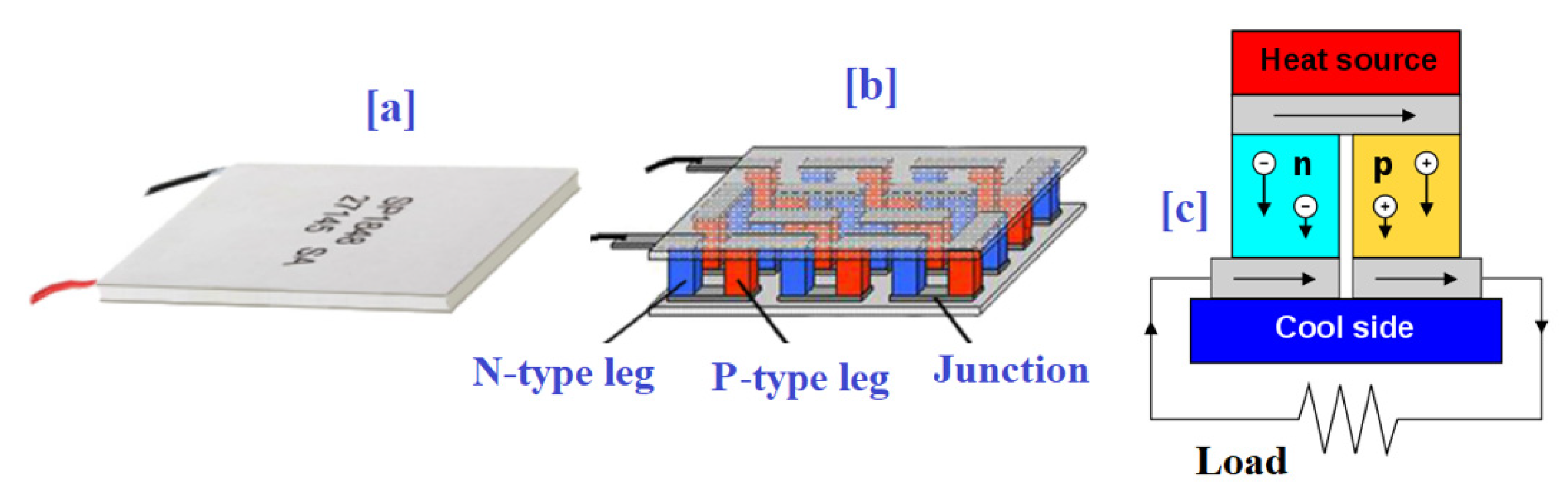
The overview of the TEG module is shown in Figure 1a. The fundamental element is a thermocouple that contains p-type and n-type semiconductors [1,2,3,4,5,6,25,26]. These conductors were electrically interconnected in series using a metal strip. To build a TEG module, several p-type and n-type pellets were interconnected together to increase the required rating of the output power as presented in Figure 1b. They were electrically linked in series to boost the voltage potential, and thermally in parallel to decrease the thermal resistance [26,29,30,31]. The couples were inserted between two parallel ceramic sheets to form a hot side and a cold side. When there was a temperature variation between the hot part and the cold part, a direct current flowed in the load as presented in Figure 1c.
The core idea of TEG modules is built according to the Seebeck impact [1,2,3,4]. The open-circuit voltage of a TEG can be estimated by applying the following formula [7,8,26]:
where and are the temperatures at the hot and cold parts of the TEG device, respectively, indicates the temperature variation between these two sides, and denotes the Seebeck coefficient.
Considering the steady-state power balance at both parts of the TEG, the absorbed heat generated by the thermal load and the heat passed by the heat sink can be formulated as follows [7,8,26]:
where indicates the thermal conductivity, is the inner resistance of the TEG, and is the TEG operating current.
The output power of the TEG can be calculated considering the variation between the heat flows at the hot and cold parts as follows:
where denotes the TEG terminal voltage output.
3. Brief Overviews on MPPT Approaches
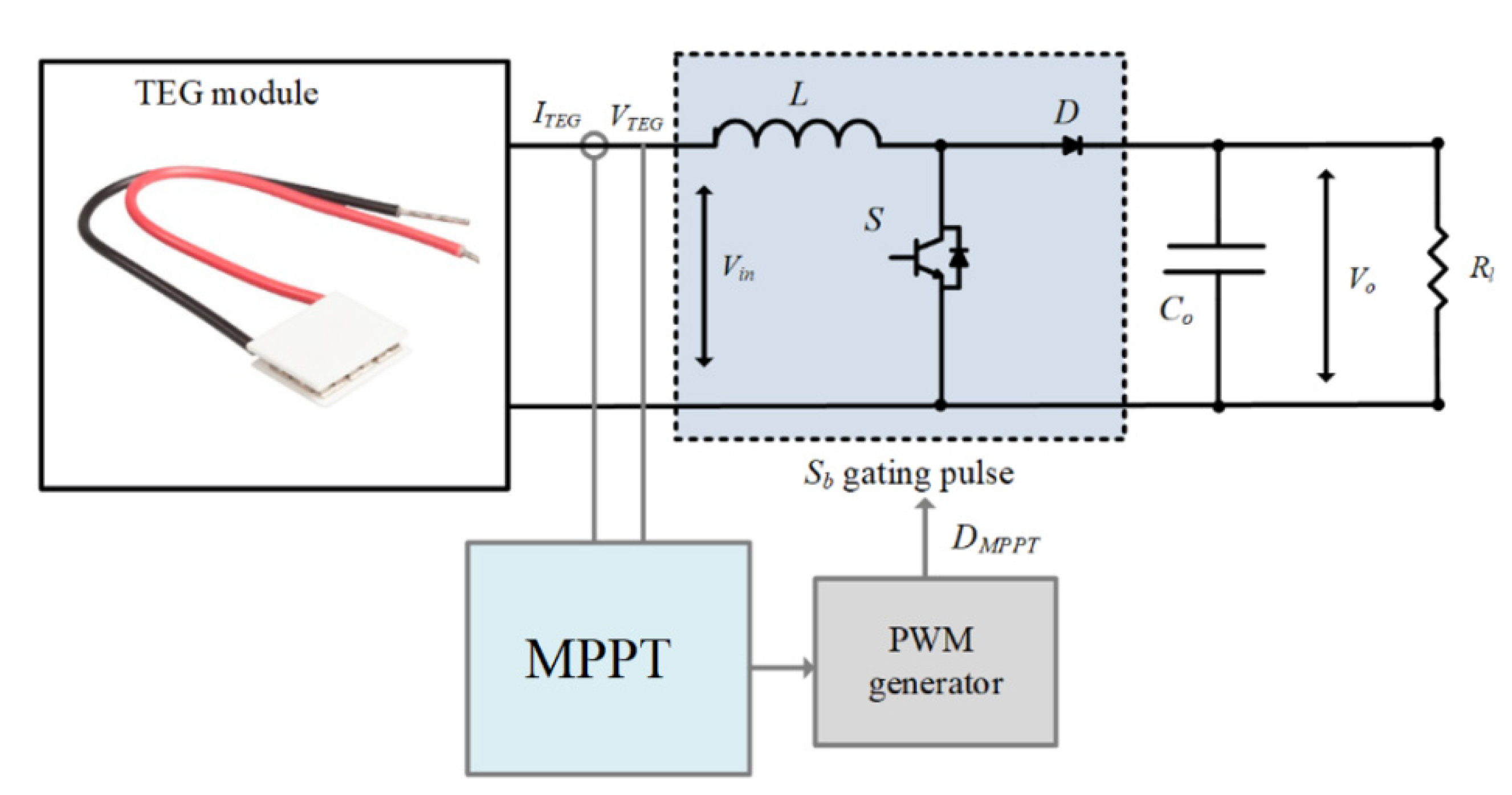
Three MPPT techniques were studied in this paper: perturb and observe, the incremental resistance method based on an integer control, and optimized incremental resistance based on a fractional-order PIλ control. In the following subsections, a brief preview of the major MPPT methods used for TEG systems is provided. The P&O and INR techniques were particularly considered. The synoptic scheme for any MPPT control approach of TEG systems is presented in Figure 2.
3.1. Perturb and Observe MPPT Method
In the MPPT formalism, P&O is considered the most frequently adopted method to track the MPP in TEG systems with a more simple structure and less algorithm complexity [7,11,14,15]. As shown in Figure 3, the P&O algorithm periodically introduces a perturbation ∆ in the operating current of TEG and contrasts the output power with that of the prior MPPT period [7,11]. A variation in the operating power was noted. As a result, if the operating current of the TEG module changed and the power increased, the P&O MPPT tracker shifted the operative point in that orientation. Otherwise, this operating point was switched in the reversed orientation.
On the other hand, the size of the perturbation ∆ is crucial in the design of a conventional P&O tracker. One can observe that the larger the value of perturbation, the faster the P&O tracker’s convergence and vice versa. Unfortunately, this perturbation size increase could lead to large fluctuations and oscillations in the output power and drive to a considerable lack of energy. Once the neighborhood of the MPP was reached, the operating point went back and forth around the MPP. Then, the P&O tracker did not precisely attain the MPP, but it fluctuated around that point undefined. To remedy this common problem, several improved P&O-based MPPT methods have been proposed in the literature for several renewable energy converters [32,33].
3.2. Incremental Resistance MPPT Technique
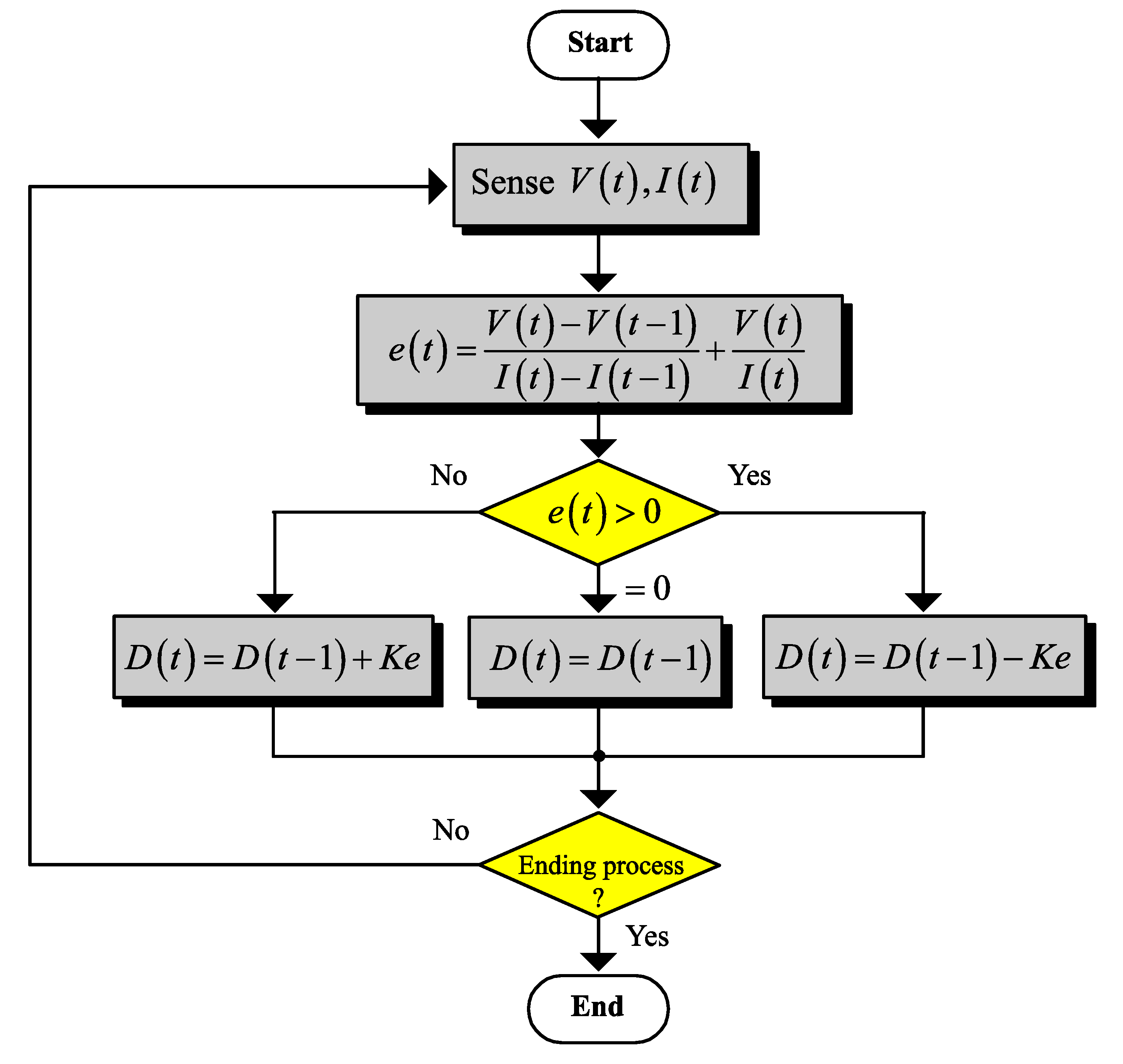
Among all the MPPT methods for TEG systems, incremental resistance techniques have been broadly adopted because of the high steady-state tracking precise and oscillations damping/reduction [7,8]. The basic concept of the INR technique is built around the truth that the derivative of the TEG power related to the TEG current (dP/dI) is zero at the MPP [20,25,26]. The slope of the TEG power characteristics is zero at the MPP, positive for values located on the left side of the MPP (amounts of output current smaller than the current at MPP) and negative for amounts located on the right side (values of output current larger than the current at the MPP). Accordingly, the error signal used by the INR-based tracker is formulated as follows:
where and are the instantaneous voltage and current of the energy converter, respectively, and denotes the increment time. The measures voltage and current are used to estimate the instantaneous power.
The maximum power output from a TEG system can be achieved by maintaining the duty cycle D (%) of the DC–DC boost converter, as the power moderator between the TEG module and the load (battery) [25,26]. The modification of such a control parameter is usually performed by the MPPT tracking algorithms to catch the most power from the TEG. A flowchart for the INR-based tracker of a TEG device is depicted in Figure 4.
Since the error signal of Equation (6) was very small around the MPP, the step size of the INR method was updated based on the value of the error signal. To achieve this and to model the INR approach, integer-order control approaches, i.e., mainly such as PID controllers and variants, were widely used in this formalism. To further improve the INR-based MPPT approach in terms of fastness response and steady-state accuracy, the techniques based on VSS-INR trackers have been proposed in the literature. In this case, the step-size parameter was directly proportional to the error signal. Therefore, the step size became small as the error was very small around the MPP. The preciseness of the VSS-INR tracking approach was further improved in the steady-state [20,21,22,23,24]. The VSS-INRT can be presented by a normal discrete integrator with the error signal as the input and a tuned gain.
4. Fractional INRT Design Problem Formulation
4.1. Preliminaries
To improve the dynamic response of the conventional incremental resistance method, a fractional-order PIλDμ-based control was adopted [34,35,36]. The fractional INRT utilizes a fractional PIλ controller instead of an integer integrator. The fractional-order control has been investigated previously in different engineering fields and showed remarkable superiority over the conventional PID approaches. Such a control structure contains a non-integer order that has several advantages such as flexibility in design and high robustness. The fractional-order PIλ transfer function can be defined as [34,35]:
where is the proportional gain, is the integral gain of the fractional PIλ controller, and indicates the non-integer order of PIλ.
4.2. Tuning Problem Formulation
The selection of fine values for the gains of the PIλ controller of Equation (7) for the OF-INRT of TEGs is often conducted by time-consuming and tedious trial–error-based procedures. This adjusting problem turned into a hard task without a systematic approach and regarding the complexity of the TEG operating conditions. To deal with these difficulties and drawbacks of classical tuning methods, the determination of these effective control parameters through an optimization program remained a promising idea. During the optimization process, the decision variables, i.e., proportional gain , integration gain , and fractional- order , were used to maximize the harvested energy from the TEG, shown as the objective function of the following formulated optimization problem:
where is the cost function that quantifies the harvest TEG energy, is the initial search space, which is considered to include targeted design gains, and and are the problem’s constraints with equality and inequality types, respectively.
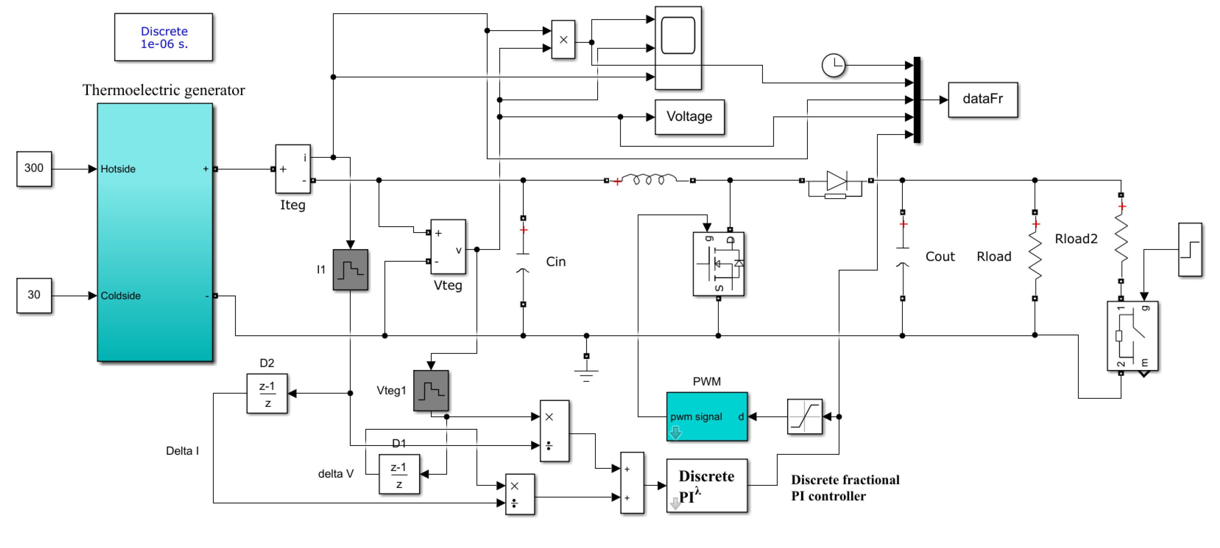
Finally, the implemented MATLAB/Simulink model of the optimized fractional-order INRT-based MPPT strategy for the studied TEG device is shown in Figure 5. The population-based SCA metaheuristic, as well as others used as comparison tools, was proposed to solve such a formulated problem. A description of all these reported algorithms is given in the following Section.
5. Algorithms for Fractional INRT Design
5.1. Sine Cosine Algorithm
The sine cosine algorithm (SCA) is a random population-based metaheuristic built based on the concepts of trigonometric functions, namely, the sine and cosine functions. Proposed by S. Mirjalili [37], the SCA metaheuristic uses these mathematical functions to detect the best solution for a given optimization issue [38,39]. Similar to other population-based metaheuristics, the SCA begins with a group of random candidate solutions, and then evaluates them frequently by an objective function and a group of motion standards. In SCA formalism, the position updating equations for both exploration and exploitation phases are given as follows:
where is the current placement of the ith candidate solution at the actual iteration and dimension , is the position of the destination point, and , , , and are random numbers uniformly distributed in the adequate intervals, where .
In the SCA’s motion Equations (9) and (10), four main control parameters were introduced [37,38,39]. The first effective design parameter dictates the movement direction, i.e., information about the next placement areas. Such an orientation could either be inside the area between the current solution and the aim or out of it. The second design parameter determines how far the solution’s motion should be towards or outwards the target. The third coefficient defines random weights for the destination to randomly assure () or deemphasize () the impact of the desalination in determining the distance. The fourth design parameter equally turns between the sine and cosine parts in the SCA’s motion Equations (9) and (10).
Finding the favorable areas of the search space with a non-premature convergence to the global optimum needs a best equilibrium between the exploration and exploitation phases. To optimally balance these two capabilities of the SCA, the range of the sine and cosine in Equations (9) and (10), given by the control parameter , were adaptively updated as follows:
where is the current iteration, is the maximum number of iterations, and is a constant parameter.
5.2. Particle Swarm Optimization
The particle swarm optimization (PSO) method is a global metaheuristic that uses a population of particles, randomly dispersed within an initially bounded search space, to detect an optimal solution for a given optimization problem [40,41]. Each particle in the swarm was titled with a vector of positions and a vector of velocities .
At the current iteration, the positions and velocities of particles changed depending on the following motion equations [41]:
where indicates the inertia factor, and define the cognitive and the social scaling parameters, and denote two random values uniformly scatted within the domain , and are the best placements previously gained by the ith particle and the whole swarm, respectively.
The exploration and exploitation mechanisms of the PSO method can be further reinforced when adopting a linear evolution technique of the inertia factor [40,41]. Such a design parameter of PSO technique was updated over iterations as follows:
where and denote the maximum and minimum values of the time-varying inertia factor typically set to 0.9 and 0.4, respectively.
5.3. Whale Optimization Algorithm
The whale optimization algorithm (WOA) is a population-based metaheuristic proposed by S. Mirjalili and A. Lewis [42]. It is a nature-inspired global algorithm which simulates the hunting behavior of humpback whales in finding and hunting their prey [42,43]. Humpback whales try to hunt and attack herds of small fish or krill that are near to the surface. This is performed by generating specific bubbles in a spiral or nine shaped paths around the prey. The WOA mimicked the bubble-net hunting mechanism to achieve the optimization. The mathematical modeling of each phase in the WOA is detailed in the following parts.
5.3.1. Encircling Prey
Whales can recognize the prey’s location in the search space and encircle them. In the WOA formalism, the position of the optimal solution is not known a priori. The algorithm assumes that the current best candidate solution is the target prey or is near to the optimum. After the best search agent is defined, the other agents try to update their positions towards the best one. Such a behavior is modeled at the current iteration by the following motion equations:
where denotes the position’s vector of humpback whales in the d-dimensional search space, is the position’s vector of the best solution obtained so far, are random numbers in the interval (0, 1), and is a real coefficient linearly decreased vector from 2 to 0 over the course of iterations.
5.3.2. Bubble-Net Hunting
This phase presents the exploitation mechanism of WOA. It can be divided into two parts: the shrinking encircling of the prey, and the spiral upward encirclement and suppression [42,43]. The shrinking behavior is performed by reducing the value of in Equation (15). The spiral updating position mimics the behavior of a humpback whale around its prey in a spiral movement according to the following equation:
where denotes the distance of the ith humpback whale to the prey, i.e., the best solution found so far, is a constant to define the form of the logarithmic spiral, and are random numbers uniformly distributed in the ranges (−1, 1) and (0, 1), respectively.
5.3.3. Search for Prey
The humpback whales explore randomly for their prey in accordance with the position of each other. Dissimilar to the exploitation technique, the updated position of a search agent was performed based on a randomly chosen search candidate rather than the best search one captured yet. This exploration technique is modeled as:
where is a random position vector, i.e., a random whale, selected from the current population of size .
6. Results and Discussion
Firstly, for examining and analyzing the output characteristics of the studied TEG device with varying temperature differences, a MATLAB code was designated. In the current study, a TEG (12611-6.0) module was considered. Table 1 presents the operational characteristics and specifications of the studied TEG.
Figure 6 illustrates the TEG’s power versus its operating current under a variation of the hot side temperature. In this design, the cold side temperature was fixed at 30 °C. Based on these demonstrative results, one can observe that there was a good agreement between the simulated data (blue line) and the manufacturing data (yellow points).
Three optimizers were stratified to evaluate the optimal gains of the introduced PIλ-based OF-INRT. These population-based metaheuristics were SCA, PSO, and WOA. In this design, the proportional gain , integration gain , and fractional order coefficient of the PIλ controller were treated as the decision variables of the formulated optimization problem. The objective function to be maximized one was the amount of the harvested energy of the TEG. For a fair comparison, the population size and the maximum number of iterations for all reported optimizers were set to 10 and 25, respectively. To validate the reliability of the reported algorithms, every optimizer was executed independently 30 times. The best parameters of the OF-INRT found for the design problem (8) applying SCA, PSO, and WOA are presented in Table 2 and Table 3. The statistical assessment of the considered optimizers is also demonstrated, i.e., results of Table 2.
Referring to Table 2, the average cost function values varied between 1.10599 W and 1.32868 W. The maximum value was achieved by the proposed SCA. The standard deviation (STD) values changed between 0.32349 and 0.00025. The minimum STD’ value was also achieved by the SCA technique. Concerning the efficiency, the maximum efficiency of 96.56% was achieved by the SCA metaheuristic, whereas the lowest efficiency of 80.33% was attained by the PSO one.
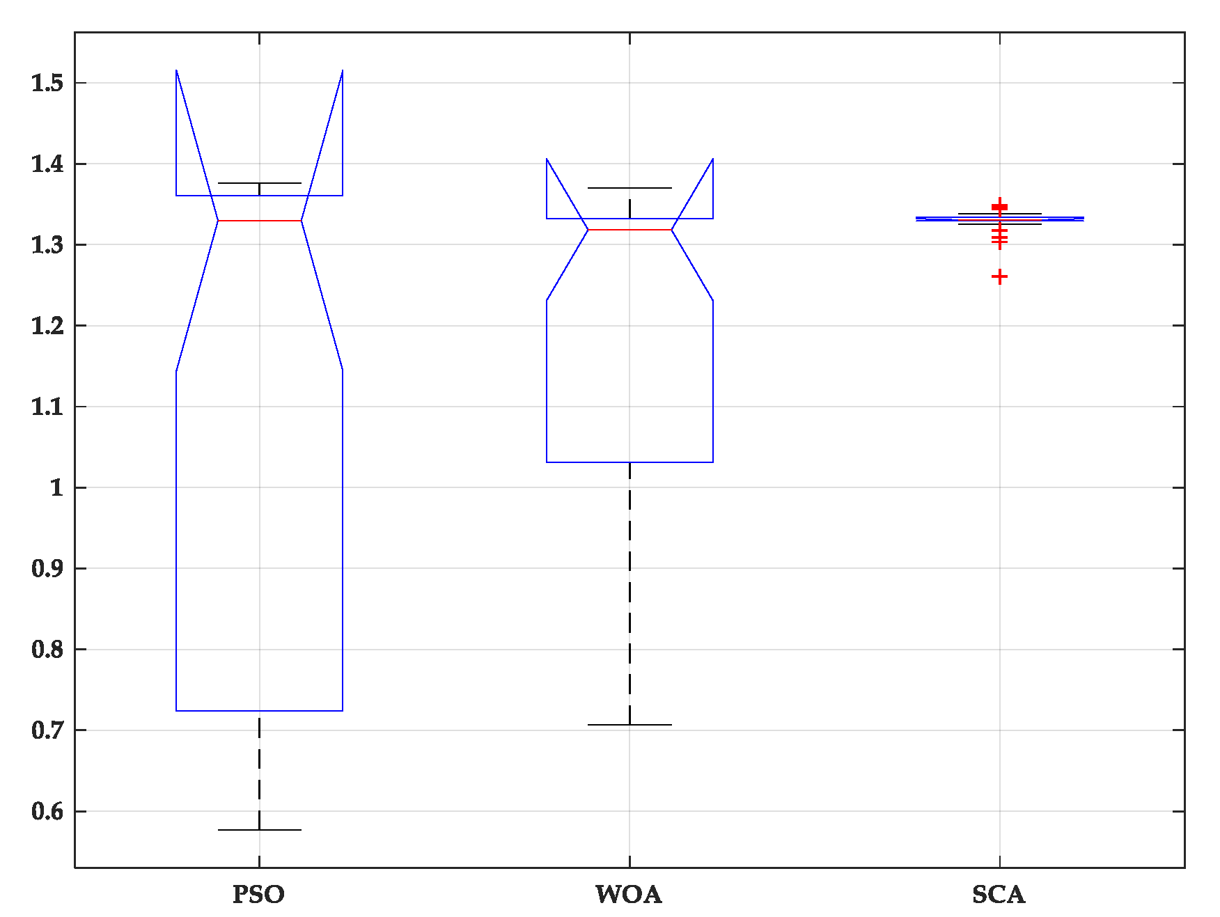
On the other hand, an analysis of the variance test (ANOVA, [44,45]) was conducted to verify the consistency of the SCA in determining the parameters of OF-INRT. ANOVA test results are presented in Table 4, and the distribution of the observations through the number of runs is presented in Figure 7. From these results, the p-value was much higher than the F value, which confirmed the difference between the provided performances. As illustrated in Figure 7, the SCA could provide the best results in terms of the mean fitness. Moreover, it had the lowest variation range where the fitness function varied from 1.26059 to 1.34877. Accordingly, the results demonstrated the SCA’s robustness and consistency.
After identifying the best gains of the proposed PIλ-based OF-INRT, the tracking performance of the SCA-based MPPT, i.e., SCA-MPPT, was examined and assessed by numerical MATLAB simulations under a changing temperature and load demand. The idea of changing the operating conditions was to investigate the tracking ability of the SCA-MPPT tracker. The scheme diagram of the system is presented in Figure 5. It includes one TEG module, DC–DC converter operating in a continuous conducted current mode with a switching frequency of 30 kHz, an input inductance of 1 mH, and an output capacitor of 47 μF. The load value was 10 Ω. At a time of 0.6 s, an extra resistance of 10 Ω was added in parallel to the load. The cold side temperature of the TEG raised from 30 °C to 50 °C at a time of 0.3 s, whereas the hot side temperature was reduced from 300 °C to 250 °C at a time of 0.3 s and then returned to 300 °C at a time of 0.9 s.
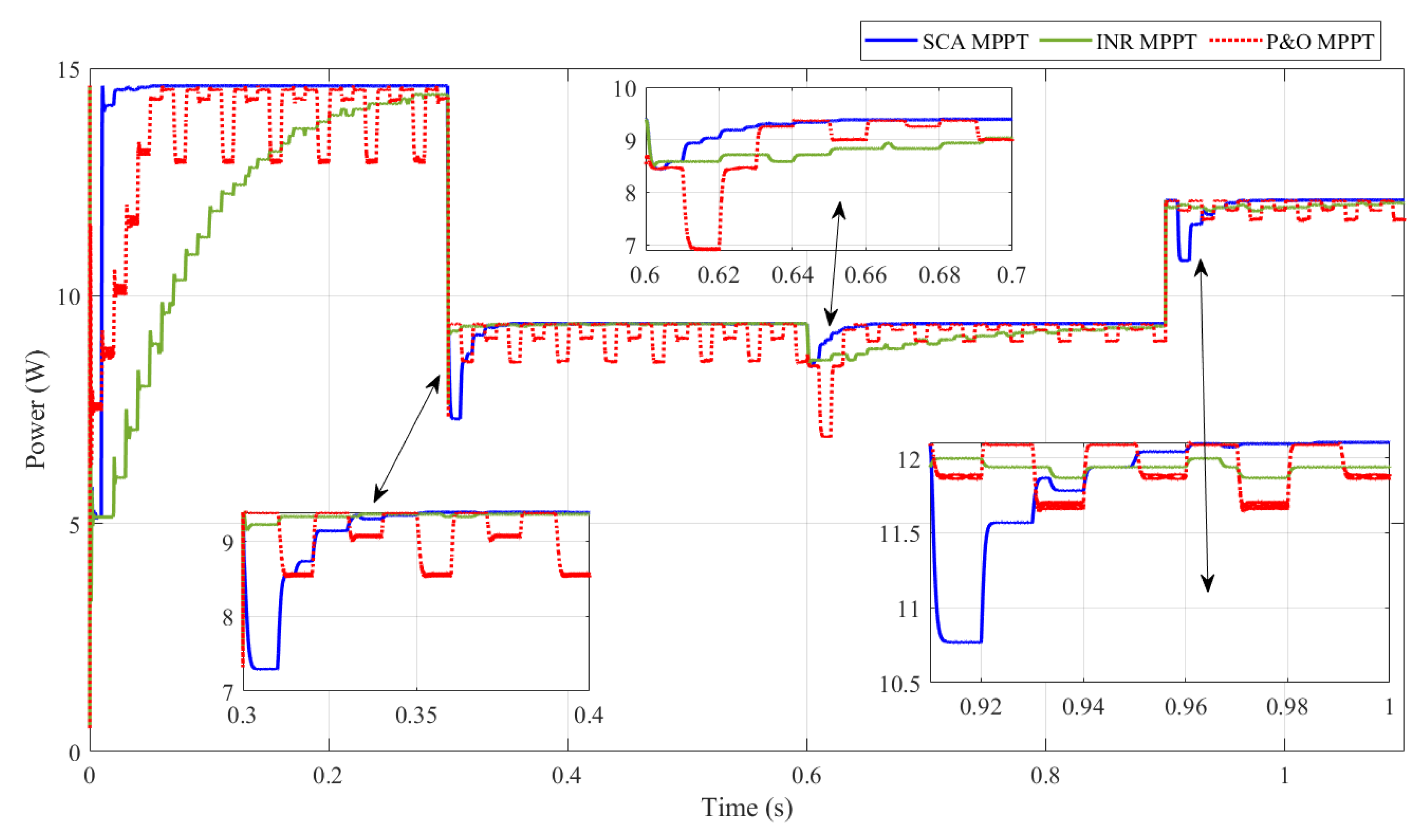
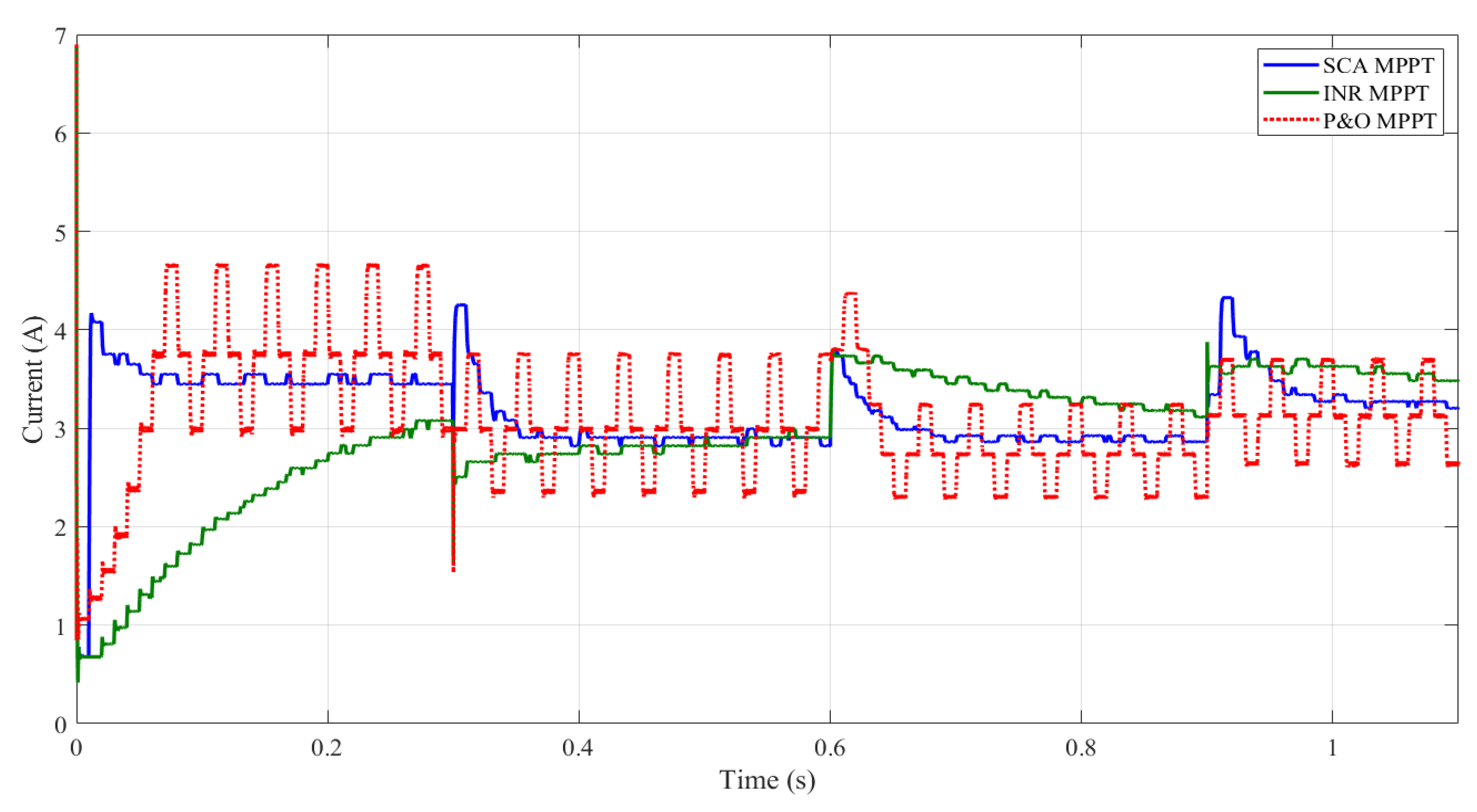
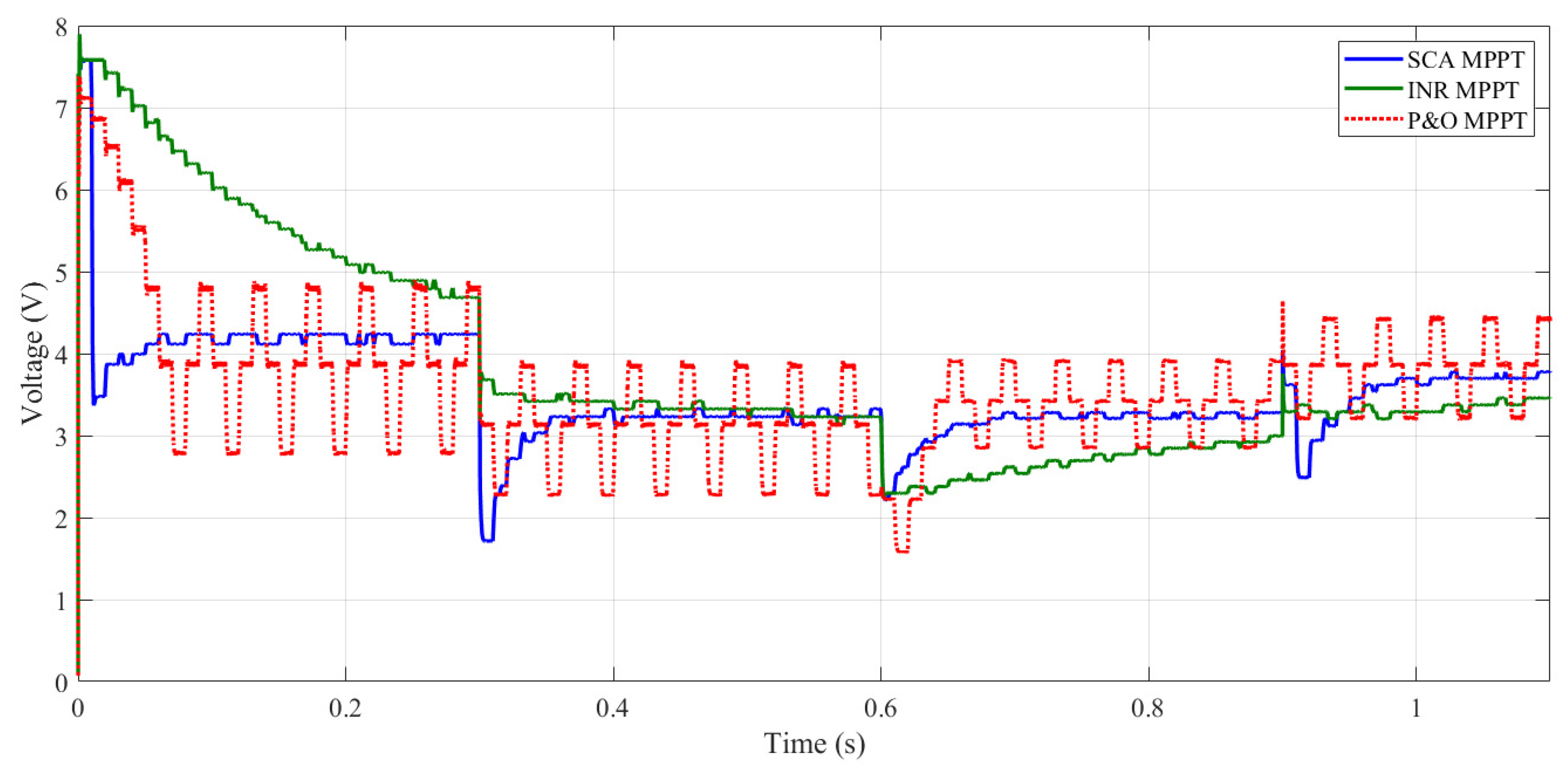
To confirm the superiority of the optimized fractional SCA-MPPT controller, the tracking ability was compared with the classical INR and P&O techniques as shown in Figure 8, Figure 9, Figure 10 and Figure 11. For the conventional INR approach, the gain of the discrete integrator was assumed to be 0.8. However, for the SCA-MPPT, the fractional PIλ controller’s parameters were 0.03765, 8.43451, and 1.01008 for the proportional gain, integral gain, and fractional-order coefficient, respectively, as summarized in Table 2. Figure 8 presents the TEG power for the three reported MPPT strategies with changing operating conditions, load, and temperature variations. Based on these conducted results, it can be noted that the SCA-MPPT reached the MPP of 14.6 W faster compared to the traditional INR and P&O MPPT techniques. The classical INR MPPT still needed more time to catch up to the MPP due to the slow dynamic response of the INR tracker. The fluctuations around the MPP were removed thanks to the SCA-based PIλ compared with the basic P&O approach. At the time of 0.3 s, the temperature difference was reduced from 270 °C to 200 °C. Therefore, the maximum output power was reduced from 14.6 W to 9.4 W. At the time of 0.6 s, the load demand deceased from 10 Ω to 5 Ω. The SCA-MPPT rapidly came back to the MPP, whereas the P&O and INR required extra time to modify the duty cycle value to attain the MPP as presented in Figure 11. In addition, at the time of 0.9 s, the difference temperature increased from 200 to 250 °C. Hence, the output power increased from 9.4 W to 12.11 W. The tracking performance of the SCA-MPPT was better than those of the INR and P&O techniques. The detailed variations of the TEG current, TEG voltage, and PWM duty cycle are presented in Figure 9, Figure 10 and Figure 11, respectively.
7. Conclusions
To improve the dynamic response of the conventional incremental resistance (INR) MPPT approach and remove the steady-state variations of the P&O MPPT technique, in this paper, an Optimized Fractional INR Tracker (OF-INRT) was proposed based on an SCA-tuned PIλ controller to rise the energy harvested from the thermoelectric generator (TEG). First, the best effective gains of the proposed OF-INRT were identified using a stochastic and parameter-free SCA. To demonstrate the superiority of the SCA optimizer, demonstrative results were carried out and compared with those obtained by the particle swarm optimization (PSO) and whale optimization algorithm (WOA)-based techniques. The results confirmed the superiority of the proposed SCA in terms of the fastness of the non-premature convergence and solution optimality. The average cost function values varied between 1.10599 W and 1.32868 W. The maximum value was achieved by the SCA tool. The STD values changed between 0.32349 and 0.00025. The minimum STD was also achieved by the SCA optimizer. Concerning the efficiency, the maximum efficiency of 96.56% has been achieved by SCA, whereas the lowest efficiency of 80.33%was is attained by PSO. In sum, the optimized fractional MPPT method succeeded to increase the dynamic response and eliminate the steady-state oscillations compared with the incremental resistance (INR) and perturb and observe (P&O) MPPT methods, respectively.
A future works process should mainly include the real-world implementation and prototyping of the introduced SCA-MPPT strategy for the studied TEG using a dSPACE board associated with the MATLAB/Simulink software toolkit. The formulation of the fractional-order INRT design problem in an online optimization framework was also investigated.
Author Contributions
Conceptualization, H.R. and S.B.; methodology, H.R., M.M.A. and S.B.; software, H.R. and M.A.-D.; formal analysis, H.R., M.M.A., M.A.-D. and S.B.; writing—original draft preparation, H.R., M.M.A., M.A.-D. and S.B.; writing—review and editing, H.R., M.M.A., M.A.-D. and S.B. All authors have read and agreed to the published version of the manuscript.
Funding
This work was supported by the Deanship of Research Oversight and Coordination (DROC) at the King Fahd University of Petroleum and Minerals (KFUPM) under Project DF191006.
Institutional Review Board Statement
Not applicable.
Informed Consent Statement
Not applicable.
Data Availability Statement
No new data were created or analyzed in this study.
Conflicts of Interest
The authors declare no conflict of interest.
References
- Jaziri, N.; Boughamoura, A.; Müller, J.; Mezghani, B.; Tounsi, F.; Ismail, M. A comprehensive review of thermoelectric generators: Technologies and common applications. Energy Rep. 2020, 6, 264–287. [Google Scholar] [CrossRef]
- Zoui, M.A.; Bentouba, S.; Stocholm, J.G.; Bourouis, M. A review on thermoelectric generators: Progress and applications. Energies 2020, 13, 3606. [Google Scholar] [CrossRef]
- Yu, J.; Zhu, Q.; Kong, L.; Wang, H.; Zhu, H. Modeling of an integrated thermoelectric generation-cooling system for thermoelectric cooler waste heat recovery. Energies 2020, 13, 4691. [Google Scholar] [CrossRef]
- Luo, D.; Wang, R.; Yu, W.; Sun, Z.; Meng, X. Modelling and simulation study of a converging thermoelectric generator for engine waste heat recovery. Appl. Therm. Eng. 2019, 153, 837–847. [Google Scholar] [CrossRef]
- Cotfas, P.A.; Cotfas, D.T. Comprehensive review of methods and instruments for photovoltaic-thermoelectric generator hybrid system characterization. Energies 2020, 13, 6045. [Google Scholar] [CrossRef]
- Sahin, A.Z.; Ismaila, K.G.; Yilbas, B.S.; Al-Sharafi, A. A review on the performance of photovoltaic/thermoelectric hybrid generators. Energy Res. 2020, 44, 3365–3394. [Google Scholar] [CrossRef]
- Ibrahim, M.N.; Rezk, H.; Al-Dahifallah, M.; Sergeant, P. Hybrid photovoltaic-thermoelectric generator powered synchronous reluctance motor for pumping applications. IEEE Access 2019, 7, 146979–146988. [Google Scholar] [CrossRef]
- Kanagaraj, N.; Rezk, H. Dynamic voltage restorer integrated with photovoltaic-thermoelectric generator for voltage disturbances compensation and energy saving in three-phase system. Sustainability 2021, 13, 3511. [Google Scholar] [CrossRef]
- Twaha, S.; Zhu, J.; Maraaba, L.; Huang, K.; Li, B.; Yan, Y. Maximum power point tracking control of a thermoelectric generation system using the extremum seeking control method. Energies 2017, 10, 2016. [Google Scholar] [CrossRef] [Green Version]
- Carstensa, J.H.; Gühmann, C. Maximum power point controller for thermoelectric generators to support a vehicle power supply. Mater. Today Proc. 2015, 2, 790–803. [Google Scholar] [CrossRef] [Green Version]
- Dalala, Z.M.; Saadeh, O.; Bdour, M.; Zahid, Z.U. A new maximum power point tracking (MPPT) algorithm for thermoelectric generators with reduced voltage sensors count control. Energies 2018, 11, 1826. [Google Scholar] [CrossRef] [Green Version]
- Park, J.; Kim, S. Maximum power point tracking controller for thermoelectric generators with peak gain control of boost DC-DC converters. J. Electron. Mater. 2012, 41, 1242–1246. [Google Scholar] [CrossRef]
- Montecucco, A.; Knox, A.R. Maximum power point tracking converter based on the open-circuit voltage method for thermoelectric generators. IEEE Trans. Power Electron. 2015, 30, 828–839. [Google Scholar] [CrossRef]
- Rezk, H.; Eltamaly, A.M. A comprehensive comparison of different MPPT techniques for photovoltaic systems. Sol. Energy 2015, 112, 1–11. [Google Scholar] [CrossRef]
- Loukriz, A.; Messalti, S.; Harrag, A. Design, simulation, and hardware implementation of novel optimum operating point tracker of PV system using adaptive step size. Int. J. Adv. Manuf. Technol. 2019, 101, 1671–1680. [Google Scholar] [CrossRef]
- Li, C.; Chen, Y.; Zhou, D.; Liu, J.; Zeng, J. A high-performance adaptive incremental conductance MPPT algorithm for photovoltaic systems. Energies 2016, 9, 288. [Google Scholar] [CrossRef] [Green Version]
- Shang, L.; Guo, H.; Zhu, W. An improved MPPT control strategy based on incremental conductance algorithm. Prot. Control. Mod. Power Syst. 2020, 5, 14. [Google Scholar] [CrossRef]
- Shengqing, L.; Fujun, L.; Jian, Z.; Wen, C.; Donghui, Z. An improved MPPT control strategy based on incremental conductance method. Soft Comput. 2020, 24, 6039–6046. [Google Scholar] [CrossRef]
- Hadji, S.; Gaubert, J.-P.; Krim, F. Maximum Power Point Tracking (MPPT) for Photovoltaic systems using open circuit voltage and short circuit current. In Proceedings of the 3rd International Conference on Systems and Control, Algiers, Algeria, 29–31 October 2013; IEEE: New York, NY, USA, 2014. [Google Scholar]
- Rezk, H.; Fathy, A. Performance improvement of PEM fuel cell using variable step-size incremental resistance MPPT technique. Sustainability 2020, 12, 5601. [Google Scholar] [CrossRef]
- Mei, Q.; Shan, M.; Liu, L.; Guerrero, J.M. A novel improved variable step-size incremental-resistance MPPT method for PV systems. IEEE Trans. Ind. Electron. 2011, 58, 2427–2434. [Google Scholar] [CrossRef]
- Liu, F.; Duan, S.; Liu, F.; Liu, B.; Kang, Y. A variable step size INC MPPT method for PV systems. IEEE Trans. Ind. Electron. 2008, 55, 2622–2628. [Google Scholar]
- Ahmed, E.M.; Orabi, M.; Shoyama, M. High Efficient Variable Step Size Incremental Resistance Maximum Power Point Tracker for PV Battery Charging Applications. In Proceedings of the 2013 IEEE Energy Conversion Congress and Exposition, Denver, CO, USA, 15–19 September 2013; IEEE: New York, NY, USA, 2013; pp. 2435–2439. [Google Scholar]
- Ahmed, E.M.; Shoyama, M. Novel Stability Analysis of Variable Step Size Incremental Resistance INR MPPT for PV Systems. In Proceedings of the 37th Annual Conference of Industrial Electronics Society, Melbourne, VIC, Australia, 7–10 November 2011; IEEE: New York, NY, USA; pp. 3894–3899. [Google Scholar]
- Kanagaraj, N. Photovoltaic and thermoelectric generator combined hybrid energy system with an enhanced maximum power point tracking technique for higher energy conversion efficiency. Sustainability 2021, 13, 3144. [Google Scholar] [CrossRef]
- Kanagaraj, N.; Rezk, H.; Gomaa, M.R. A variable fractional order fuzzy logic control based MPPT technique for improving energy conversion efficiency of thermoelectric power generator. Energies 2020, 13, 4531. [Google Scholar] [CrossRef]
- Tang, S.; Sun, Y.; Chen, Y.; Zhao, Y.; Yang, Y.; Szeto, W. An enhanced MPPT method combining fractional-order and fuzzy logic control. IEEE J. Photovolt. 2017, 7, 640–650. [Google Scholar] [CrossRef]
- Al-Dhaifallah, M.; Nassef, A.M.; Rezk, H.; Nisar, K.S. Optimal parameter design of fractional order control based INC-MPPT for PV system. Sol. Energy 2018, 159, 650–664. [Google Scholar] [CrossRef]
- Quan, R.; Li, T.; Yue, Y.; Chang, Y.; Tan, B. Experimental study on a thermoelectric generator for industrial waste heat recovery based on a hexagonal heat exchanger. Energies 2020, 13, 3137. [Google Scholar] [CrossRef]
- Meng, J.-H.; Wu, H.-C.; Wang, T.-H. Optimization of two-stage combined thermoelectric devices by a three-dimensional multi-physics model and multi-objective genetic algorithm. Energies 2019, 12, 2832. [Google Scholar] [CrossRef] [Green Version]
- Li, X.; Xie, C.; Quan, S.; Shi, Y.; Tang, Z. Optimization of thermoelectric modules’ number and distribution pattern in an automotive exhaust thermoelectric generator. IEEE Access 2019, 7, 72143–72157. [Google Scholar] [CrossRef]
- Kamran, M.; Mudassar, M.; Fazal, M.R.; Asghar, M.U.; Bilal, M.; Asghar, R. Implementation of improved perturb & observe MPPT technique with confined search space for standalone photovoltaic system. J. King Saud Univ.-Eng. Sci. 2020, 32, 432–441. [Google Scholar]
- Gil-Velasco, A.; Aguilar-Castillo, C. A modification of the perturb and observe method to improve the energy harvesting of PV systems under partial shading conditions. Energies 2021, 14, 2521. [Google Scholar] [CrossRef]
- Zheng, W.; Luo, Y.; Chen, Y.; Wang, X. A simplified fractional order PID controller’s optimal tuning: A case study on a PMSM speed servo. Entropy 2021, 23, 130. [Google Scholar] [CrossRef]
- Liu, L.; Zhang, S. Robust fractional-order PID controller tuning based on Bode’s optimal loop shaping. Complexity 2018, 2018, 6570560. [Google Scholar] [CrossRef]
- Edet, E.; Katebi, R. On Fractional-order PID controllers. IFAC-PapersOnLine 2018, 51, 739–744. [Google Scholar] [CrossRef]
- Mirjalili, S. SCA: A sine cosine algorithm for solving optimization problems. Knowl.-Based Syst. 2016, 96, 120–133. [Google Scholar] [CrossRef]
- Gabis, A.B.; Meraihi, Y.; Mirjalili, S.; Ramdane-Cherif, A. A comprehensive survey of sine cosine algorithm: Variants and applications. Artif. Intell. Rev. 2021. [Google Scholar] [CrossRef]
- Abualigah, L.; Diabat, A. Advances in sine cosine algorithm: A comprehensive survey. Artif. Intell. Rev. 2021, 54, 2567–2608. [Google Scholar] [CrossRef]
- Clerc, M.; Kennedy, J. The particle swarm: Explosion, stability, and convergence in a multidimensional complex space. IEEE Trans. Evol. Comput. 2002, 6, 58–73. [Google Scholar] [CrossRef] [Green Version]
- Bouallègue, S.; Haggège, J.; Ayadi, M.; Benrejeb, M. PID-type fuzzy logic controller tuning based on particle swarm optimization. Eng. Appl. of Artif. Intell. 2012, 25, 484–493. [Google Scholar] [CrossRef]
- Mirjalili, S.; Lewis, A. The whale optimization algorithm. Adv. Eng. Softw. 2016, 95, 51–67. [Google Scholar] [CrossRef]
- Alhato, M.M.; Bouallègue, S. Whale optimization algorithm for active damping of LCL-filter-based grid-connected converters. Int. J. Renew. Energy Res. 2019, 9, 986–996. [Google Scholar]
- Pereira, D.G.; Afonso, A.; Medeiros, F.M. Overview of Friedman’s test and post-hoc analysis. Commun. Stat.-Simul. and Comput. 2015, 44, 2636–2653. [Google Scholar] [CrossRef]
- Derrac, J.; García, S.; Molina, D.; Herrera, F. A practical tutorial on the use of nonparametric statistical tests as a methodology for comparing evolutionary and swarm intelligence algorithms. Swarm Evol. Comput. 2011, 1, 3–18. [Google Scholar] [CrossRef]
Figure 1.
Hardware structure of a TEG module. (a) Overview of the TEG module; (b) P-type and N-type pellets, and (c) TEG circuit.
Figure 1.
Hardware structure of a TEG module. (a) Overview of the TEG module; (b) P-type and N-type pellets, and (c) TEG circuit.

Figure 2.
MPPT control scheme of a TEG system.

Figure 3.
Flowchart of P&O-based MPPT method.

Figure 4.
Flowchart of INR-based MPPT technique.

Figure 5.
MATLAB/Simulink model of the OF-INRT-based MPPT.

Figure 6.
TEG power against current.

Figure 7.
ANOVA test results.

Figure 8.
Detailed system performance with different MPPTs under load and temperature variation: TEG power.
Figure 8.
Detailed system performance with different MPPTs under load and temperature variation: TEG power.

Figure 9.
Detailed system performance with different MPPTs under load and temperature variation: TEG current.
Figure 9.
Detailed system performance with different MPPTs under load and temperature variation: TEG current.

Figure 10.
Detailed system performance with different MPPTs under load and temperature variation: TEG voltage.
Figure 10.
Detailed system performance with different MPPTs under load and temperature variation: TEG voltage.

Figure 11.
Detailed system performance with different MPPTs under load and temperature variation: PWM duty cycle.
Figure 11.
Detailed system performance with different MPPTs under load and temperature variation: PWM duty cycle.


Table 1.
Specifications of the TEG (12611-6.0).
| Characteristics | Specification |
|---|---|
| Hot side temperature | 300 °C |
| Cold side temperature | 30 °C |
| Open-circuit voltage | 8.4 V |
| Matched load resistance | 1.2 Ω |
| Matched load voltage | 4.2 V |
| Matched load current | 3.4 A |
| Matched load power | 14.6 W |
Table 2.
Optimal gains of the OF-INRT and statistical evaluations (30 runs).
| PSO | WOA | SCA | |
|---|---|---|---|
| 0.03346 | 0.0332 | 0.03765 | |
| 06.6776 | 5.47598 | 8.43451 | |
| 0.98458 | 00.9425 | 1.01008 | |
| Best | 01.3757 | 1.36972 | 1.34877 |
| Worst | 0.57694 | 0.70707 | 1.26059 |
| Average | 1.10599 | 1.16222 | 1.32868 |
| Median | 1.32888 | 00.2287 | 0.01591 |
| Variance | 0.10465 | 1.31844 | 1.33071 |
| STD | 0.32349 | 00.0523 | 0.00025 |
| Efficiency (%) | 80.3339 | 84.4638 | 96.5610 |
Table 3.
Details of 30 runs using the considered optimizers.
| Run | PSO | WOA | SCA | Run | PSO | WOA | SCA |
|---|---|---|---|---|---|---|---|
| 1 | 0.7275 | 1.04516 | 1.34397 | 16 | 1.36184 | 0.71506 | 1.32962 |
| 2 | 1.32642 | 1.36731 | 1.30919 | 17 | 0.60096 | 1.31844 | 1.33071 |
| 3 | 1.36623 | 1.33082 | 1.32548 | 18 | 1.34176 | 1.35291 | 1.33043 |
| 4 | 1.32796 | 1.21181 | 1.32965 | 19 | 0.68507 | 1.32879 | 1.32971 |
| 5 | 1.36341 | 1.36972 | 1.30332 | 20 | 1.37222 | 0.70707 | 1.33192 |
| 6 | 0.78113 | 1.33076 | 1.26059 | 21 | 1.31299 | 1.03375 | 1.31771 |
| 7 | 1.3757 | 1.34959 | 1.33083 | 22 | 0.70488 | 1.33196 | 1.33343 |
| 8 | 1.33915 | 0.83358 | 1.33339 | 23 | 1.37224 | 1.03113 | 1.34716 |
| 9 | 1.36749 | 1.30094 | 1.34877 | 24 | 1.34435 | 1.03126 | 1.33854 |
| 10 | 1.33397 | 1.36757 | 1.32855 | 25 | 0.68323 | 1.32933 | 1.33411 |
| 11 | 0.71208 | 1.03375 | 1.31771 | 26 | 1.35098 | 0.71506 | 1.32962 |
| 12 | 1.32979 | 1.33196 | 1.33343 | 27 | 0.61278 | 1.31844 | 1.33071 |
| 13 | 0.57694 | 1.03113 | 1.34716 | 28 | 1.36042 | 1.35291 | 1.33043 |
| 14 | 1.33174 | 1.03126 | 1.33854 | 29 | 0.73653 | 1.32879 | 1.32971 |
| 15 | 0.79199 | 1.32933 | 1.33411 | 30 | 1.28803 | 0.70707 | 1.33192 |
Table 4.
ANOVA test results.
| Source | SS | df | MS | F | p-Value > F |
|---|---|---|---|---|---|
| Columns | 0.78479 | 2 | 0.3924 | 7.65 | 0.001 |
| Error | 4.36282 | 84 | 0.05194 | ||
| Total | 5.14761 | 86 |
Publisher’s Note: MDPI stays neutral with regard to jurisdictional claims in published maps and institutional affiliations. |
© 2021 by the authors. Licensee MDPI, Basel, Switzerland. This article is an open access article distributed under the terms and conditions of the Creative Commons Attribution (CC BY) license (https://creativecommons.org/licenses/by/4.0/).
Share and Cite
MDPI and ACS Style
Rezk, H.; Alhato, M.M.; Al-Dhaifallah, M.; Bouallègue, S. A Sine Cosine Algorithm-Based Fractional MPPT for Thermoelectric Generation System. Sustainability 2021, 13, 11650. https://doi.org/10.3390/su132111650
AMA Style
Rezk H, Alhato MM, Al-Dhaifallah M, Bouallègue S. A Sine Cosine Algorithm-Based Fractional MPPT for Thermoelectric Generation System. Sustainability. 2021; 13(21):11650. https://doi.org/10.3390/su132111650
Chicago/Turabian StyleRezk, Hegazy, Mohammed Mazen Alhato, Mujahed Al-Dhaifallah, and Soufiene Bouallègue. 2021. "A Sine Cosine Algorithm-Based Fractional MPPT for Thermoelectric Generation System" Sustainability 13, no. 21: 11650. https://doi.org/10.3390/su132111650
Note that from the first issue of 2016, this journal uses article numbers instead of page numbers. See further details here.