Article

A Wirelessly Powered Smart Contact Lens with Reconfigurable Wide Range and Tunable Sensitivity Sensor Readout Circuitry

1
Department of Electrical and Computer Engineering, National Chiao-Tung University, Room 617, Engineering Building 5, No. 1001, Ta Hsueh Rd., Hsinchu 30010, Taiwan
2
Institute of Electrical Control Engineering, National Chiao-Tung University, Room 617, Engineering Building 5, No. 1001, Ta Hsueh Rd., Hsinchu 30010, Taiwan
*
Author to whom correspondence should be addressed.
Sensors 2017, 17(1), 108; https://doi.org/10.3390/s17010108
Submission received: 14 November 2016 / Revised: 19 December 2016 / Accepted: 30 December 2016 / Published: 7 January 2017
(This article belongs to the Special Issue Smart Sensor Interface Circuits and Systems)

Abstract

:
This study presented a wireless smart contact lens system that was composed of a reconfigurable capacitive sensor interface circuitry and wirelessly powered radio-frequency identification (RFID) addressable system for sensor control and data communication. In order to improve compliance and reduce user discomfort, a capacitive sensor was embedded on a soft contact lens of 200 μm thickness using commercially available bio-compatible lens material and a standard manufacturing process. The results indicated that the reconfigurable sensor interface achieved sensitivity and baseline tuning up to 120 pF while consuming only 110 μW power. The range and sensitivity tuning of the readout circuitry ensured a reliable operation with respect to sensor fabrication variations and independent calibration of the sensor baseline for individuals. The on-chip voltage scaling allowed the further extension of the detection range and prevented the implementation of large on-chip elements. The on-lens system enabled the detection of capacitive variation caused by pressure changes in the range of 2.25 to 30 mmHg and hydration level variation from a distance of 1 cm using incident power from an RFID reader at 26.5 dBm.

1. Introduction

An increase in on-lens sensors presents an attractive proposition to maximize the procurement of eye health information to the maximum possible extent. The geometry and size constraints of a contact lens necessitate components that are miniature and compact to fit in the lens. Hence, a wirelessly powered smart contact lens (SCL) system with a reconfigurable capacitance-to-digital converter (CDC) was proposed in this study. The proposed soft contact lens was fabricated with hydroxyethyl methacrylate (HEMA) hydrogel and a commercial manufacturing process to improve edge configuration, compliance, and comfort [1]. Intraocular pressure (IOP) measurement for glaucoma prevention was used to illustrate the functionality of the proposed SCL system in the study.
Continuous IOP monitoring in glaucoma patients with high accuracy and high reliability is constantly required to enable prompt detection and daily tracking [2]. Methods were proposed for continuous and long-term IOP monitoring by using an implant pressure sensor [3,4,5] and eye curvature monitoring [6]. Pressure sensor implants are invasive and require surgery, thereby reducing patient compliance. Additionally, the implants usually require high incident wireless power to operate the devices, and this could cause a rise in the temperature of eye tissues. In contrast, the on-lens eye curvature method is less invasive and can provide direct access to the eye surface with minimal disturbances. However, the sensors are typically fabricated on hard silicone or plastic materials [6], and thus lead to discomfort in terms of long-term wear.
Previous studies demonstrated a microelectromechanical system (MEMS) capacitive pressure sensor on a contact lens [7,8] and sensor chips [9,10] for long-term IOP monitoring. An extant study demonstrated the wireless harvesting of smart contact lens and antenna design [10]. This study involved proposing a reconfigurable CDC to improve the capacitance detection characteristics and demonstrated the functionalities of a wirelessly powered SCL system. The results indicated improvements in the capacitance detection range and sensitivity when compared with those of the CDC as reported in previous studies [9,10]. The rest of the paper is organized as follows: Section 2 describes published research that includes studies examining system design, antennae, sensor chips, and capacitive sensors; Section 3 describes the improved sensor readout circuitry and contact lens assembly process; Section 4 discusses the results of experimental investigations of the wirelessly operated SCL system. Finally, conclusions and discussions are presented in Section 5.

2. Related Work

This section briefly summarizes extant research including system design, antennae, sensor chips, and capacitive sensors.

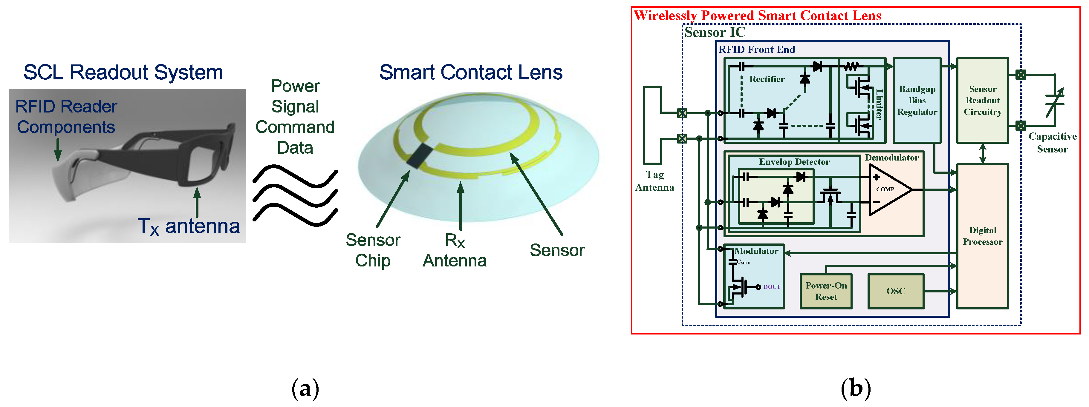
2.1. System and Sensor Chip Design

A previous study [9] presented an integrated wireless SCL system as shown in Figure 1a,b. The SCL system included a capacitive sensor for eye healthcare monitoring, a silicon chip with readout circuitry and an ultra-high frequency (UHF) radio-frequency identification (RFID) Gen-2 wireless transceiver, and a small loop antenna. The SCL system communicated with an on-glass RFID reader for sensing data collection and sensor control.
Figure 1b shows the architecture of a proposed sensor chip. The sensor chip includes the analog front-end circuits for power scavenging and data demodulation, a digital processor for protocol format generation and sensing information processing, and a sensor readout circuitry to acquire the sensor information. A capacitive sensor was employed in the design to detect eye curvature changes due to IOP deviations. The measured capacitance value was converted to a bit-stream format for further digital processing. Size constraints on the lens led to low antenna efficiency and low energy storage capability and limited the available power on the lens. Therefore, low power electronics design and efficient power management were crucial in the proposed system. Furthermore, separated regulators were used in the design to avoid noise coupling between digital and analog circuits, that is, the analog supply voltage for sensitive sensor readout circuitry and the low-voltage supply for digital circuits. In order to evaluate the radio frequency (RF) front end performance, the chip was measured using standard RFID testing equipment (CISC RFID Xplorer) [11] that allowed programming instructions to be sent to the RFID tags using standard RFID commands or user-defined commands by following the protocol definition. A continuous wave signal from the CISC RFID Xplorer was directly connected to the RF input of the proposed sensor chip for measurement purposes. The rectifier with an RF input level of 1.74 mW (2.4 dBm) had a power conversion efficiency (PCE) of 11.2% and produced 3.13 V across a 50-kΩ load, which was sufficient for circuit operations of the proposed sensor chip. Detailed descriptions of blocks and measurements could be found in previous studies [9,10].

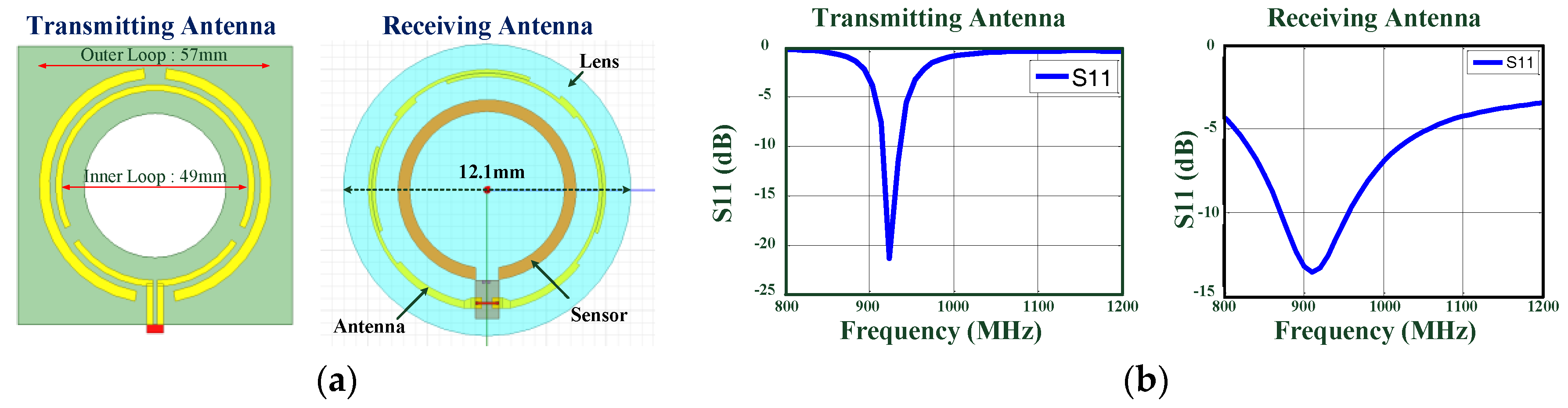
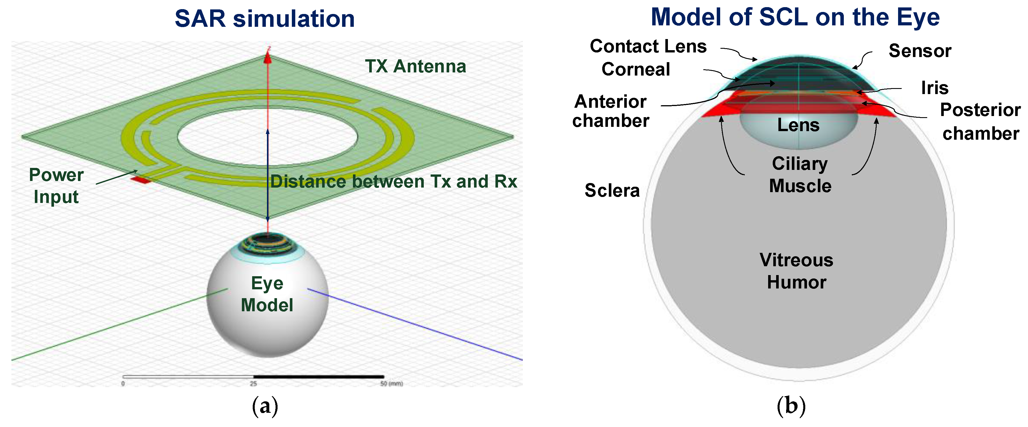
2.2. Wireless Energy Harvesting and Antenna Design

In addition to the low power consumption requirement of sensor chips, limiting the energy source needed to sustain long-term sensing is another critical challenge for a wirelessly powered SCL system. It was challenging to supply the on-lens device with sufficient energy over an extended lifetime [12]. The sensor chip was wirelessly powered by an external electromagnetic (EM) energy source to avoid the need for batteries on the lens. It was also necessary to minimize the power consumption of the wireless monitoring system to sustain long-term bio-signal acquisition using low RF power. In conjunction with path and tissue losses, the relative location of the power transmitter (on the glasses) and receiver (on the lens) affects the amount of power received, especially for highly oriented small-size antennae. Thus, ring-type geometry was used in the sensor and antenna design due to the need to restrict the area of the components to avoid vision blockage. It was also necessary for the lens thickness to be close to that of commercial products to reduce contact lens discomfort [1]. This makes it difficult to locate matching and tuning components on the lens. A single-turn loop receiving antenna for UHF operation was implemented on the contact lens subject to these constraints. Impedance matching between the RFID sensor chip and antenna was achieved using the antenna profile by changing the segment length of the two wires and the gap spacing between them. Figure 2a,b shows the prototypes and simulation results of the transmitting and receiving antennas, respectively. In order to further improve power transfer, a segmented antenna with a gap between the two loops was used to create a uniform magnetic field distribution [13]. The uniform field distribution of the proposed transmitting antenna could enhance energy transmission and provide robust operation with respect to shifts in the relative location and alignment of the contact lens and the glass caused by eye movement and blinking.
For safety reasons, it was necessary to maintain the increase in eye temperature under RF exposure to less than 1 °C [14]. An eye model with seven tissues [15], as shown in Figure 3a,b, was used to investigate the tissue influence and the specific absorption rate (SAR). The temperature increase in the eye tissue under short-term EM exposure can be obtained by a linear approximation of the bio-heat equation [14] as follows:
S A R = c Δ T Δ t
where c denotes the heat capacity of the tissue, ΔT denotes the temperature change, and Δt denotes the exposure time. The maximum increase in temperature following 1 s of 30 dBm EM exposure corresponded to only 0.008 °C at 10 mm and 0.002 °C at 20 mm. A previous study discussed and summarized wireless energy harvesting, antenna design, and impact on eye tissues [10].

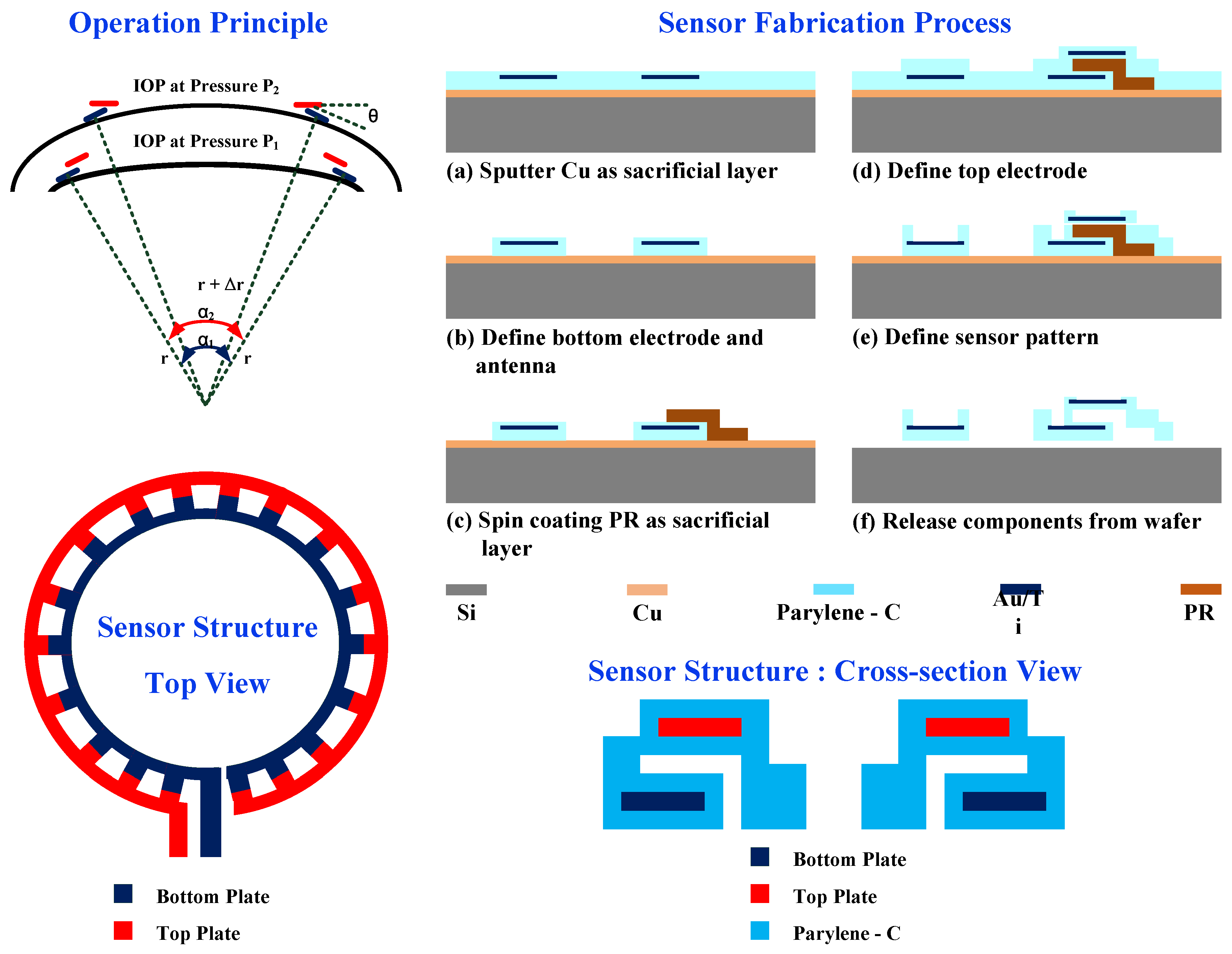
2.3. Capacitive Sensor Design

Extant studies [7,8] presented the design and fabrication of an IOP capacitive sensor. Figure 4 shows the principle and fabrication process of the IOP capacitive sensor. The contact lens was placed tightly on the surface of the cornea, and thus the distance between the on-lens electrodes followed the curvature changes due to the IOP changes (from P1 to P2). The total capacitance is derived as follows:
C ( θ ( α ) ) = N ε r ε 0 w tan θ ln d l tan θ + l sin θ d l tan θ , θ ( α ) π 2 ( Δ r + d ) + α r r + Δ r + d
where N denotes the number (18) of parallel capacitors, d denotes the gap distance (10 µm), α denotes the angle between two ends of the capacitive sensor, and w (400 µm) and l (100 µm) denote the unit width and unit length of a unit capacitor, respectively. A micro capacitive sensor using top-down parallel plates was fabricated using MEMS methods on the HEMA substrate. The fabrication process is described as follows. First, a sacrificial copper (Cu) layer was sputtered on the Parylene-C substrate. The areas of the bottom capacitor electrodes and the loop antenna were formed by a lift-off process with titanium (Ti; 600 Å) and gold (Au; 3500 Å) and defined by a reactive-ion etching mask. The insulating layer was implemented with Parylene-C with 1 µm thickness. The upper electrode was also formed with Titanium (Ti; 600 Å) and gold (Au; 3500 Å), which were defined after the photolithography and the lift-off process. Finally, the Cu sacrificial layer and the sacrificial layer between the parallel metal layers were removed. The sensor was placed on the inner area, and the antenna was placed outside a contact lens to maximize the effective area and efficiency.
In order to verify the characteristics of the capacitor sensor, the ex vivo porcine eye connected to a syringe pump was filled with increasing and decreasing amounts of water to generate periodical intraocular pressure variations between 0 mmHg and 4.5 mmHg for measurement. The measurements indicated that the sensitivity of the fabricated capacitive sensor corresponded to 4.4 fF/mmHg [8]. To compensate for the capacitance variation of the on-lens sensor owing to dielectric variation and various wearers’ eye conditions, the required capacitance detection range of sensor the readout circuitry was extended to 120 pF [7,8].

3. Materials and Methods

The SCL system included a capacitive sensor for eye healthcare monitoring, a silicon chip with readout circuitry and a UHF RFID Gen-2 wireless transceiver, and a small loop antenna. A reconfigurable capacitive sensor readout circuitry that occupied the same chip size as that used in a previous study [10] was employed in the design to overcome sensor variations during the fabrication and baseline drift of various wearers’ eye conditions. The sensor chip of our on-lens system is an integrated single chip solution dedicated to smart contact lens applications; and the chip size and geometrical dimensions were more optimized as compared with those of reported works [16,17,18,19]. The SCL system communicated with an on-glass RFID reader for sensing data collection, sensor control, and calibration for individuals. Furthermore, the on-lens system used commercially available bio-compatible HEMA hydrogel with a standard thickness of 200 μm and a commercial manufacturing process to reduce discomfort and increase compliance.

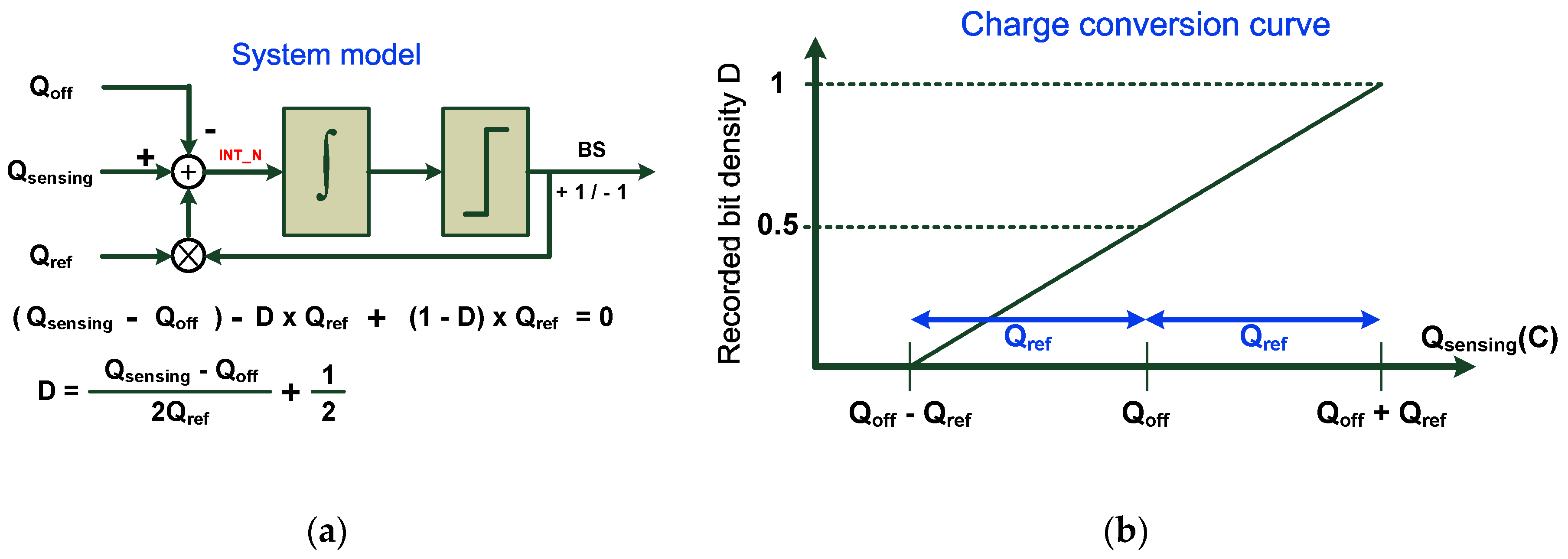
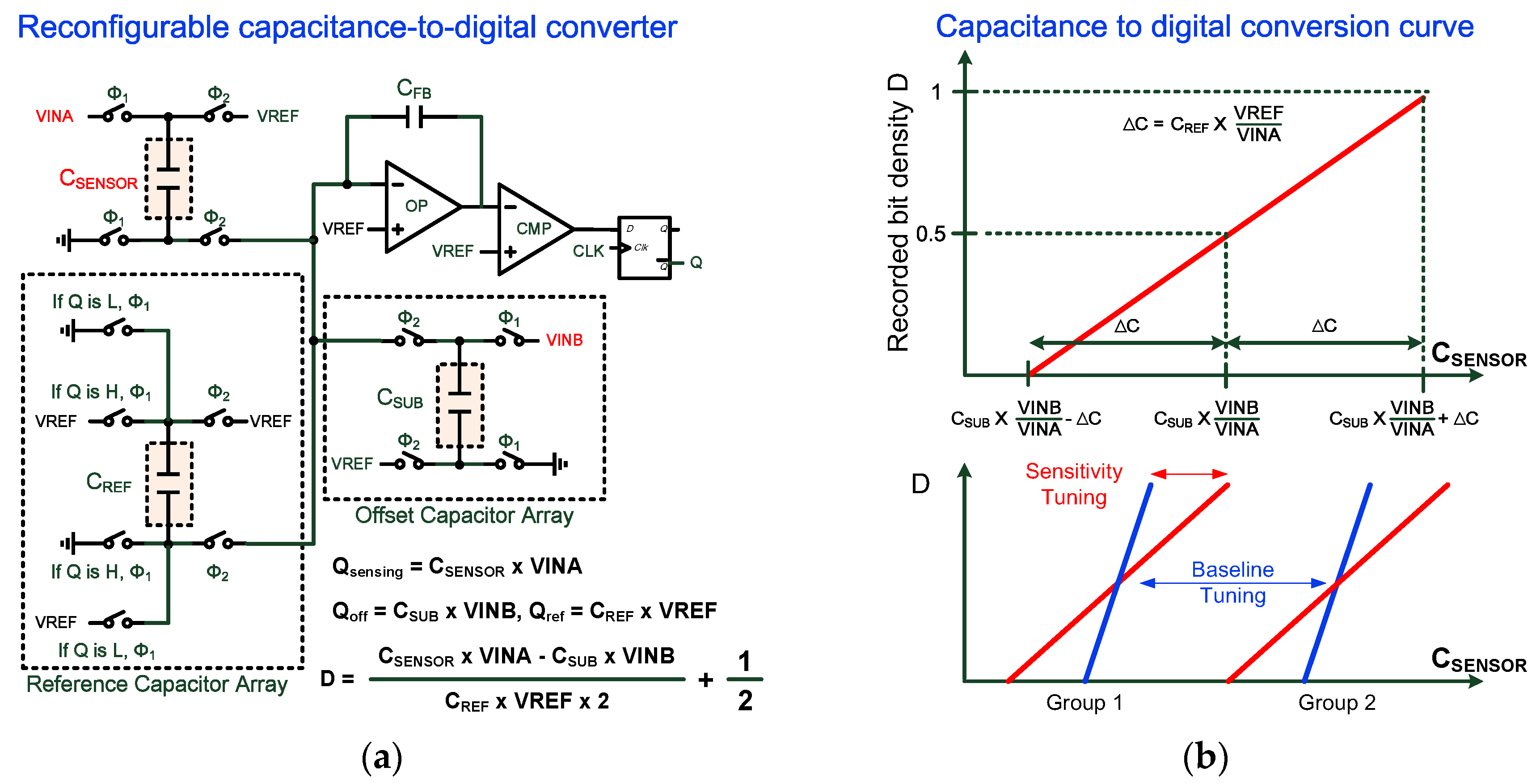
3.1. Design of the Sensor Readout Circuitry

Capacitive sensor interfaces are widely used when compared with resistive sensors due to inherent energy benefits and the absence of static current requirements [20,21]. The reconfigurable CDC proposed in this study provided moderate resolution, low power consumption, and a small chip area. It also simultaneously ensured the maximization of detection sensitivity as well detection range, and thus the proposed CDC was extremely suitable for the on-lens system in the study when compared with the CDCs reported in previous studies [20,21,22,23].
In order to improve the linearity and resolution of the readout circuitry, a 1-bit delta-sigma (Δ-Σ) modulator was adopted to convert the measured sensor value to a digital bit stream. The recorded bit density represented the relationship between the on-chip reference and the sensor value under the test. The converted digital bit stream was fed to a digital counter, and a decimation filter was used to remove undesired high-frequency fluctuations and out-of-band noise. The system model is shown in Figure 5a, and a charge balancing process was used to illustrate the converter operation [20]. The negative feedback in the modulator ensured charge balance and resulted in a zero average charge flowing into the loop filter [20] as follows:
( Q sensing Q off ) D × Q ref + ( 1 D ) × Q ref = 0
where D denotes the bit density of the output bit stream BS (0 ≤ D ≤ 1). Solving for D results in the following expression:
D = Q sensing Q off 2 × Q ref + 1 2
which corresponds to the desired representation of the sensing charge Qsensing. The center of the charge conversion curve is denoted by Qoff, and the offset charge (denoted as Qoff) provides flexibility for baseline tuning. The sensitivity of conversion was inversely proportional to Qref, and the reference charge Qref provided sensitivity tuning and a detection range of 2Qref. The charge conversion curve is summarized in Figure 5b.
The proposed reconfigurable CDC as shown in Figure 6a consisted of several capacitance arrays, an integrator, a comparator, an analog signal generator, and digital control circuits. For capacitive sensing, Qsensing = VINA × CSENSOR, Qoff = VINB × CSUB, and QREF = VREF × CREF. The capacitance detection range of the proposed CDC is as follows:
C SUB × V I N B V I N A C REF × V R E F V I N A C SENSOR C SUB × V I N B V I N A + C REF × V R E F V I N A
where VREF, VINA, and VINB denote the on-chip scalable voltage references, CREF denotes the reference capacitor, and CSUB denotes the offset capacitor. Additionally, CSUB is used for coarsely tuning the capacitor range, and CREF is applied for sensitivity tuning of the conversion gain. Voltage scaling of VINB/VINA was used to further extend the capacitance detection range and prevented the implementation of large on-chip capacitors. The conversion behaviors of the proposed reconfigurable CDC are summarized in Figure 6b. The capacitor arrays and voltage references are wirelessly controlled by the commands from the on-glass RFID reader, and the maximum sensitivity and wide detection range could be simultaneously achieved with this topology.

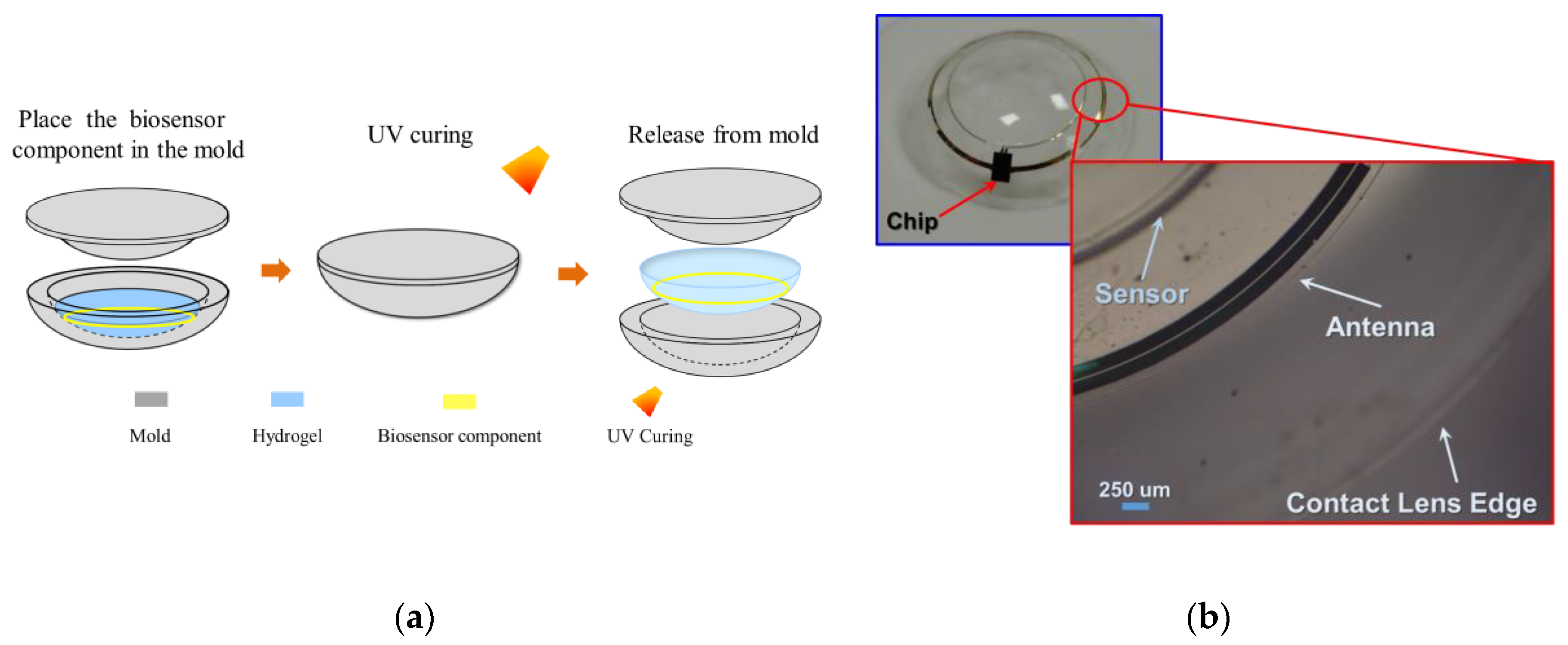
3.2. Contact Lens Assembly Process

A general cast molding method was used to integrate the chip, receiving antenna, and biosensor on a soft contact lens with commercially available biocompatible materials. In order to reduce contact lens discomfort and increase compliance, it was necessary to fit the design of the contact lens to a standard (normal/universal/general) contact lens specification [1] involving thicknesses of 200 μm and 100 um at the peripheral and optical areas, respectively, of a contact lens. In this study, a standard contact lens fabrication process was utilized for the proposed smart contact lens packaging with hydrogel-based material. Figure 7a shows the process flow of the hydrogel-based contact lens biosensor system package with a pair of convex and concave contact lens molds. In the process, the proposed biosensor component was placed on a concave mold, and its center was aligned with the center of the mold. This was followed by pouring a hydrogel material into a concave mold and then combining the convex and concave molds. The contact lens with the molds was then cured with ultraviolet (UV) light. Finally, the mold was immersed into a hydration solution to facilitate a hydration reaction in the de-molding process. During the reaction, the contact lenses in the molds absorbed water to become soft and then could easily be detached from the molds. The proposed assembly process was compatible with a standard contact lens process, and it improved the edge smoothness and flatness of the contact lens. The assembly method helped in achieving a wrinkle-free smart contact lens as shown in Figure 7b.

4. Results

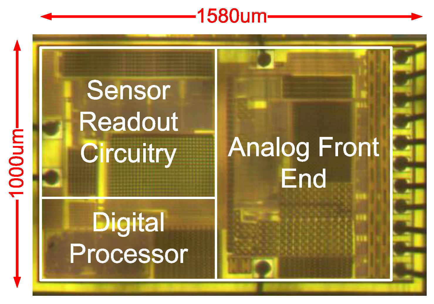
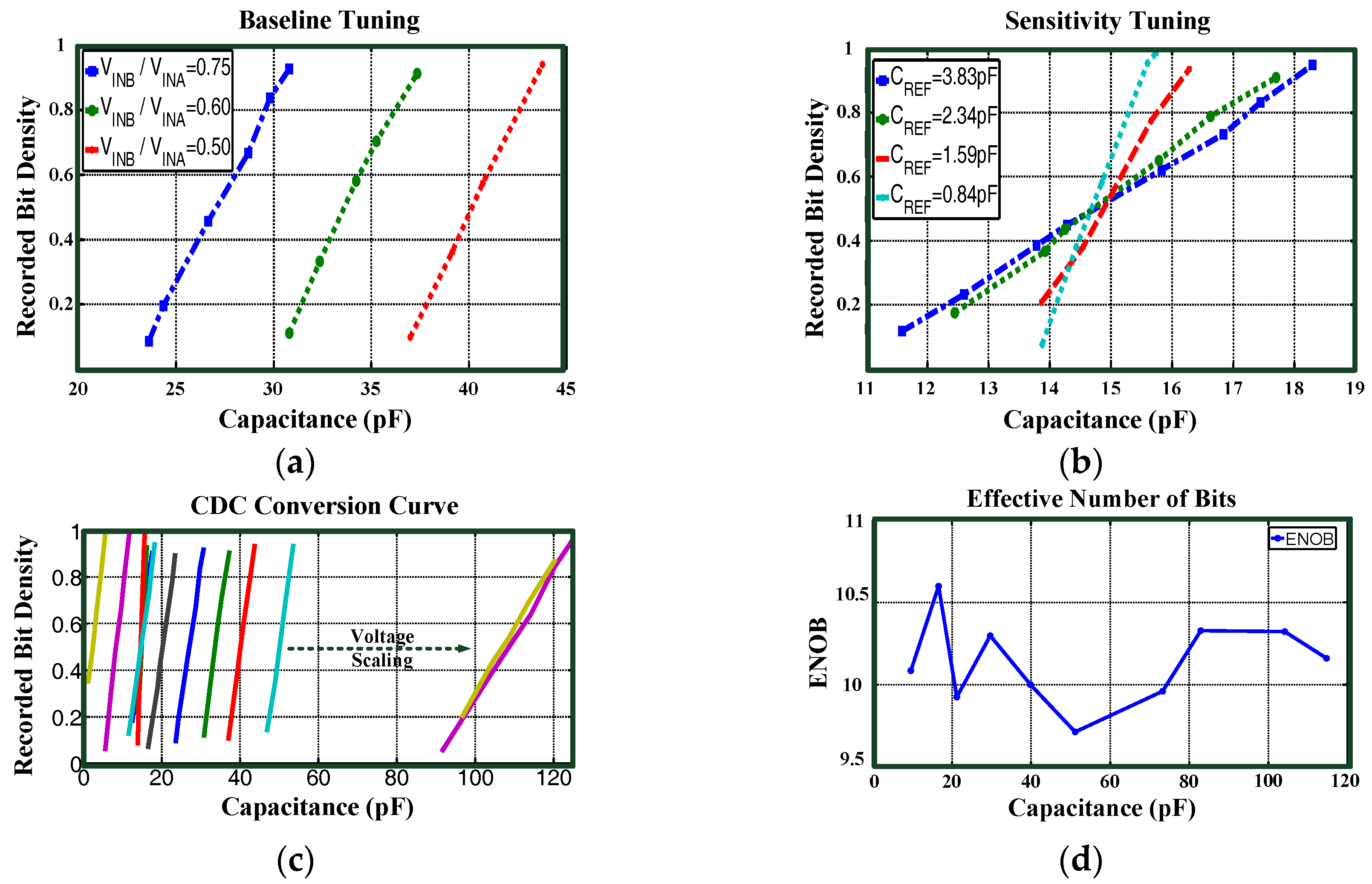
4.1. Sensor Chip Experiments

Figure 8 shows the chip micrograph of the proposed sensor IC. The chip was implemented using 0.18 μm CMOS technology. The dimensions of the chip with input and output pads corresponded to 1 mm × 1.58 mm, and the CDC chip area corresponded to 0.64 mm × 0.64 mm. The proposed CDC topology extended the maximum capacitance detection range from 50 pF to 120 pF within the same chip area when compared with that in a previous study [10]. The sensitivity was improved and could be tuned wirelessly by command programming.
In order to confirm the sensor readout circuitry characteristics, the wired chip bonded on a print circuit board (PCB) was connected to commercial capacitors up to 120 pF for static capacitance conversion testing. The sensor chip was wirelessly powered by 20 dBm incident RF power from the RFID reader at a distance of 2 cm. Different reference capacitance values (denoted as CREF) were selected for sensitivity tuning, and different voltage scaling ratios VINB/VINA were selected for baseline tuning. In order to evaluate the CDC conversion resolution, the effective number of bits (ENOB) calculation, as defined in a previous study [24], was used. The conversion results are shown in Figure 9. Table 1 shows performance summary and comparison with state-of-the-art CDC.

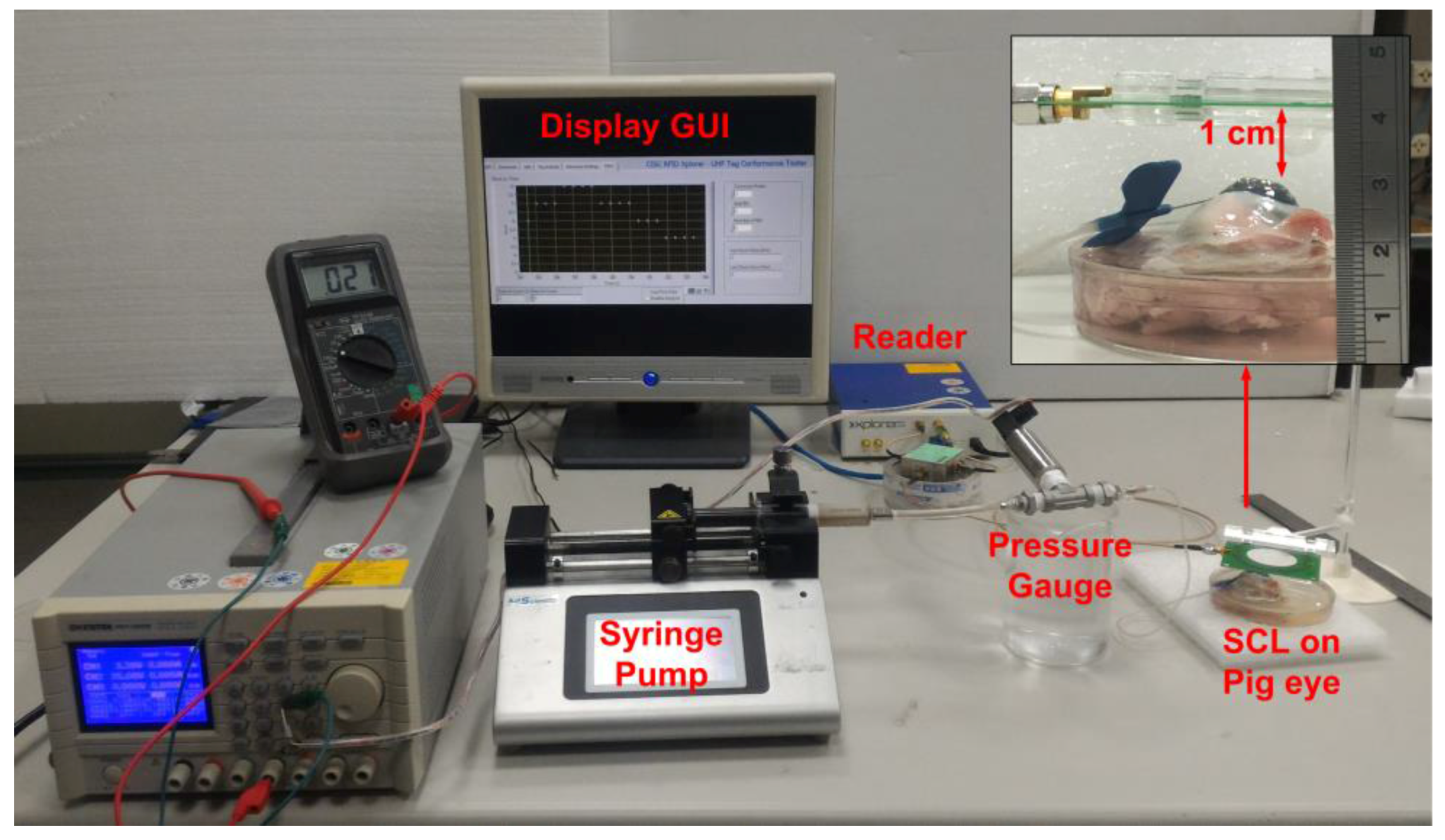
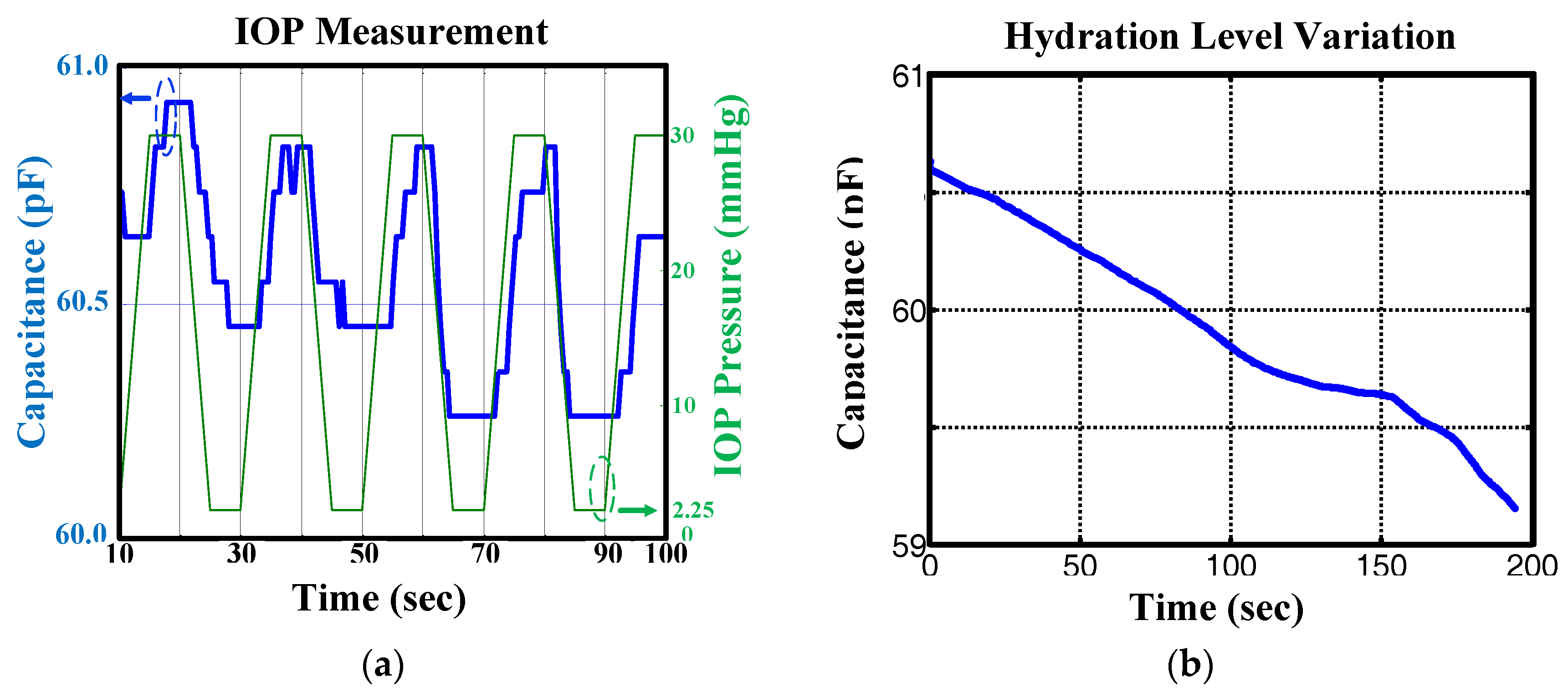
4.2. Wirelessly Powered SCL Expeiments

The porcine eye (LYD pigs, Guan Dong Market, Hsinchu city, Taiwan, R.O.C) connected to a syringe pump was filled with increasing and decreasing amounts of water to generate periodical intraocular pressure variations in the range of 2.25 and 30 mmHg for measurement purposes. A 20 s pressure variation period was used in the study. The RFID reader was placed at a distance of 1 cm to wirelessly record IOP pressure variation. The photograph of the measurement setup is shown in Figure 10.
The sensor lens was wirelessly powered by a 26.5 dBm incident RF power from the RFID reader at 920 MHz frequency. Real-time periodical IOP measuring data were directly monitored on a PC and recorded for future clinical study purposes. The recorded periodical IOP pressure variation is shown in Figure 11a. As indicated by the measurement results, the dynamic range of sensor readout circuitry of the proposed sensor lens achieved the IOP range requirement of 2.25–30 mmHg. There is a time delay between the capacitance variation and pressure gauge readings because the IOP is changed by the increasing and decreasing amounts of water. The water was injected and then drained from the pig eye to change the IOP, thus causing a time delay. In addition to IOP measurement, the dielectric capacity increased as the water content increased and vice versa. Figure 11b shows the long-term capacitance change due to the hydration level variation from SCL with the same experiment setup as that shown in Figure 10. The measurements indicated that the proposed SCL could also be used for hydration level detection in the future. Table 2 compares the results with those of state-of-the-art IOP monitoring systems. The proposed design achieved a power consumption of only 110 μW and used RFID addressable communication for sensor control and data communication. With the proposed CDC topology, the maximum sensitivity and wide detection range can be achieved simultaneously. The sensor chip of our on-lens system is an integrated single chip solution dedicated to smart contact lens applications; the chip size and geometrical dimensions were more optimized as compared with those of reported works [3,5,6]. Moreover, the proposed sensor system integrated with a 200-μm thickness contact lens using HEMA hydrogel and standard process can improve discomfort and compliance issues related to contact lenses.

5. Discussion and Conclusions

In this study, a wirelessly powered smart contact lens system was proposed for non-invasive and long-term IOP monitoring. The system was composed of an energy transmitter, antennae, and an on-lens sensing device. The proposed SCL system could be wirelessly powered and was able to communicate with commercial Gen2 RFID-compatible equipment to demonstrate periodical IOP pressure variation and hydration level variation measurements. The on-lens system used commercially available bio-compatible HEMA hydrogel with a standard 200-μm thickness and a commercial manufacturing process, and this reduced discomfort and increased compliance. A successful sensor readout distance of 1 cm was achieved under 26.5-dBm incident RF power at a UHF RFID frequency of 920 MHz. The proposed design exhibited low power consumption and was fully integrated onto contact lens material using a standard manufacturing process. The range and sensitivity tuning of reconfigurable readout circuitry provided a reliable operation over sensor fabrication variations. Hydration level detection will be examined in future studies to further extend the application of the proposed SCL system.

Acknowledgments

This work was supported in part by the Ministry of Science and Technology, Taiwan, R.O.C. (under Contract Number: MOST 105-2218-E-009-018 and MOST 103-2221-E-009-192-MY3). The authors would like to thank the National Chip Implementation Center for chip fabrication. The authors express their gratitude to CISC Semiconductor for technical assistance for the CISC RFID Xplorer.

Author Contributions

All authors considerably contributed to this article. The article was conceived and structured by all the authors who contributed to writing, reading and approving the final manuscript. Jin-Chern Chiou performed the conceptual design. Shun-Hsi Hsu performed the system integration and measurements, and developed the sensor chip. Yu-Chieh Huang performed the system validation. Guan-Ting Yeh and Wei-Ting Liou developed an on-lens capacitive sensor and performed sensor fabrication and contact lens assembly. Cheng-Kai Kuei performed the antenna design and implementation. Jin-Chern Chiou, Shun-Hsi Hsu, Yu-Chieh Huang, Guan-Ting Yeh, Wei-Ting Liou, and Cheng-Kai Kuei wrote the paper.

Conflicts of Interest

The authors declare no conflict of interest.

References

  1. Sirinivasan, S.; Subbaraman, L.N. The science of contact lens discomfort. Opt. J. Rev. Optom. 2015, 152, 34–39. [Google Scholar]
  2. Piso, D.; Veiga-Crespo, P.; Vecino, E. Modern monitoring intraocular pressure sensing devices based on application specific integrated circuits. J. Biomater. Nanobiotechnol. 2012, 3, 301–309. [Google Scholar] [CrossRef]
  3. Chow, E.Y.; Chlebowski, A.L.; Oqui, P.P. A miniature-implantable RF-wireless active glaucoma intraocular pressure monitor. IEEE Trans. Biomed. Circuits Syst. 2010, 4, 340–349. [Google Scholar] [CrossRef] [PubMed]
  4. Chen, G.; Ghaed, H.; Haque, R.; Wieckowski, M.; Kim, Y.; Kim, G.; Fick, D.; Kim, D.; Seok, M.; Wise, K.; et al. A cubic-millimeter energy-autonomous wireless intraocular pressure monitor. In Proceedings of the IEEE International Solid-State Circuits Conference Digest of Technical Papers, San Francisco, CA, USA, 20–24 February 2011; pp. 310–311.
  5. Donida, A.; Dato, G.D.; Cunzolo, P.; Sala, M.; Piffaretti, F.; Orsatti, P.; Barrettino, D. A 0.036 mbar circadian and cardiac intraocular pressure sensor for smart implantable lens. In Proceedings of 2015 IEEE International Solid-State Circuits Conference, San Francisco, CA, USA, 22–26 February 2015; pp. 392–393.
  6. Leonardi, M.; Pitchon, E.; Bertsch, A.; Renaud, P.; Mermoud, A. Wireless contact lens sensor for intraocular pressure monitoring: Assessment on enucleated pig eyes. Acta Ophthalmol. 2009, 87, 433–437. [Google Scholar] [CrossRef] [PubMed]
  7. Chiou, J.C.; Huang, Y.C.; Yeh, G.T. A capacitor-based sensor and a contact lens sensing system for intraocular pressure monitoring. J. Micromech. Microeng. 2015, 26, 015001. [Google Scholar] [CrossRef]
  8. Yeh, G.T.; Wu, T.W.; Tsai, S.W.; Hsu, S.H.; Chiou, J.C. Toward a wireless contact lens sensor system with a micro-capacitor for intraocular pressure monitoring on in vitro porcine eye. In Proceedings of the IEEE Sensors, Busan, Korea, 1–4 November 2015; pp. 1–4.
  9. Hsu, S.H.; Chiou, J.C.; Liao, Y.T.; Yang, T.S.; Kuei, C.K.; Wu, T.W.; Huang, Y.C. An RFID-based on-lens sensor system for long-term IOP monitoring. In Proceedings of the 37th Annual International Conference IEEE Engineering in Medicine and Biology Society, Milan, Italy, 25–29 August 2015; pp. 7526–7529.
  10. Chiou, J.C.; Hsu, S.H.; Liao, Y.T.; Huang, Y.C.; Yeh, G.T.; Kuei, C.K.; Dai, D.K. Toward a wirelessly powered on-lens intraocular pressure monitoring system. IEEE J. Biomed. Health Inform. 2016, 20, 1216–1224. [Google Scholar] [CrossRef] [PubMed]
  11. CISC RFID Xplorer Equipment Information. Available online: https://www.cisc.at/products/rfid-xplorer (accessed on 11 December 2016).
  12. Yang, G.Z. Body Sensor Networks; Springer: London, UK, 2006. [Google Scholar]
  13. Qing, X.; Goh, C.K.; Chen, Z.N. Eye-shaped segmented reader antenna for near-field UHF RFID applications. Electron. Lett. 2009, 45, 872–873. [Google Scholar] [CrossRef]
  14. IEEE Standard for Safety Levels With Respect to Human Exposure to Radio Frequency Electromagnetic Fields, 3 kHz to 300 GHz; IEEE Std C95.1-2005 (Revision of IEEE Std C95.1-1991); IEEE: New York, NY, USA, April 2006.
  15. Wessapan, T.; Rattanadecho, P. Specific absorption rate and temperature increase in the human eye due to electromagnetic fields exposure at different frequencies. Int. J. Heat Mass Transf. 2013, 64, 426–435. [Google Scholar] [CrossRef]
  16. LPS25H MEMS Pressure Sensor. Available online: http://www.st.com/en/mems-and-sensors/lps25h.html (accessed on 11 December 2016).
  17. ANDY100—RFID Tag Chips that Supply and Communicate with External Sensors. Available online: http://www.farsens.com/en/products/andy100 (accessed on 11 December 2016).
  18. SL900A EPC Sensor Tag—EPC Sensor Tag and Data Logger IC. Available online: http://ams.com/eng/Products/Wireless-Connectivity/Sensor-Tags-Interfaces/SL900A (accessed on 11 December 2016).
  19. Cho, N.; Song, S.J.; Kim, S.Y.; Kim, S.H.; Yoo, H.J. A 5.1-μW UHF RFID tag chip integrated with sensors for wireless environmental monitoring. In Proceedings of the 31st European Solid-State Circuits Conference, Grenoble, France, 12–16 September 2005; pp. 279–282.
  20. Tan, Z.; Daamen, R.; Humbert, A.; Ponomarev, Y.V.; Chae, Y.; Pertijs, M.A.P. A 1.2-V 8.3-nJ CMOS humidity sensor for RFID applications. IEEE J. Solid-State Circuits 2013, 48, 2469–2477. [Google Scholar] [CrossRef]
  21. Oh, S.; Lee, Y.; Wang, J.; Foo, Z.; Kim, Y.; Jung, W.; Li, Z.; Blaauw, D.; Sylvester, D. A dual-slope capacitance-to-digital converter integrated in an implantable pressure-sensing system. IEEE J. Solid-State Circuits 2015, 50, 1581–1591. [Google Scholar] [CrossRef]
  22. Tan, Z.; Shalmany, S.H.; Meijer, G.C.M.; Pertijs, M.A.P. An energy-efficient 15-bit capacitive-sensor interface based on period modulation. IEEE J. Solid-State Circuits 2012, 47, 1703–1711. [Google Scholar] [CrossRef]
  23. Xia, S.; Makinwa, K.; Nihtianov, S. A capacitance-to-digital converter for displacement sensing with 17b resolution and 20 μs conversion time. In Proceedings of 2012 IEEE International Solid-State Circuits Conference Digest of Technical Papers (ISSCC), San Francisco, CA, USA, 19–23 February 2012; pp. 198–199.
  24. Heidary, A.; Meijer, G.C.M. Features and design constraints for an optimized SC front-end circuit for capacitive sensors with a wide dynamic range. IEEE J. Solid-State Circuits 2008, 43, 1609–1616. [Google Scholar] [CrossRef]
Figure 1. (a) Proposed smart contact lens (SCL) system architecture; (b) Block diagram of the proposed smart contact lens.
Sensors 17 00108 g001
Figure 2. (a) Prototypes of transmitting (left) and receiving antennas (right); (b) Simulated |S11| of transmitting antenna (left) and receiving antenna (right).
Sensors 17 00108 g002
Figure 3. (a) Configuration of the simulation; (b) Eye model for specific absorption rate (SAR) simulation.
Sensors 17 00108 g003
Figure 4. Principle and fabrication process of the capacitive pressure sensor.
Sensors 17 00108 g004
Figure 5. (a) System model of the capacitance-to-digital converter (CDC); (b) Charge conversion curve of the CDC.
Sensors 17 00108 g005
Figure 6. (a) A schematic of the proposed reconfigurable CDC; (b) Conversion curve and tuning behaviors of CDC.
Sensors 17 00108 g006
Figure 7. (a) Contact lens assembly process; (b) Assembled wrinkle free soft contact lens.
Sensors 17 00108 g007
Figure 8. Die photo of the proposed sensor chip.
Sensors 17 00108 g008
Figure 9. (a) Baseline tuning of the CDC; (b) Sensitivity tuning of the CDC; (c) CDC conversion curves; (d) The ENOB of the CDC.
Sensors 17 00108 g009
Figure 10. The experimental setup.
Sensors 17 00108 g010
Figure 11. (a) Intraocular pressure (IOP) measurement results; (b) Hydration level measurement results.
Sensors 17 00108 g011
Table 1. A comparison of the performance of the capacitance-to-digital converter used in the present study to those used in previous studies.
[20][21][22][23]This Work
TypeΔ-ΣDual-SlopePWMΔ-ΣΔ-Σ
Input Range0.54–1.06 pF5.3–30.7 pF1–6.8 pF8.4–11.6 pF1.5–120 pF
Chip Area0.28 mm2N/A0.51 mm22.6 mm20.41 mm2
Power10.3 μW110 nW210 μW14.9 mW100 μW
ENOB12.5 bits7.05 bits15 bits15.3 bits9.7 bits
Table 2. A comparison of the intraocular pressure monitoring system in the present study with those used in previous studies.
References[3][5][6]This Work
TypeImplantableImplantableWearableWearable
Communication TechniqueActiveLoad ModulationN/ALoad Modulation
Frequency2.5 GHz13.56 MHz27 MHz920 MHz
Power Consumption1.4 mW1.2 mWN/A110 μW
Communication DistanceN/A4 cmN/A1 cm
Sensor TypeCapacitiveResistiveResistiveCapacitive
Sensor Range5.3 pF–5.75 pF5 KΩ–50 KΩN/A1.5 pF–120 pF
ENOBN/A8N/A9.7
Chip Size0.5 mm22 mm2N/A1.58 mm2
Communication ProtocolN.AISO-15693N/AEPC Class1 Gen2
Lens ThicknessN/AN/A400 μm200 μm
Lens MaterialN/AN/ASiliconeHEMA

