Azimuth Ambiguity Suppression for Hybrid Polarimetric Synthetic Aperture Radar via Waveform Diversity


1
Department of Space Microwave Remote Sensing System, Aerospace Information Research Institute, Chinese Academy of Sciences, Beijing 100190, China
2
University of the Chinese Academy of Sciences, Beijing 100039, China
*
Author to whom correspondence should be addressed.
Remote Sens. 2020, 12(7), 1226; https://doi.org/10.3390/rs12071226
Submission received: 13 February 2020
/
Revised: 5 April 2020
/
Accepted: 9 April 2020
/
Published: 10 April 2020
(This article belongs to the Section Remote Sensing Communications)
Abstract
:Hybrid quadrature polarimetric (hybrid quad-pol) synthetic aperture radar (SAR) is proposed as a potential candidate for the full-polarimetric SAR mode. It allows balanced range ambiguity performance and simplified system structure. System based on hybrid-pol SAR mode can also implement the conventional quad-pol mode and the compact-pol mode via few adjustments. However, the azimuth ambiguity performance in cross-pol channels is proved deteriorated in hybrid quad-pol mode due to the lopsided energy distribution of ambiguities. As are generally called “ghost” targets, azimuth ambiguities usually influence the recognition of the targets in SAR imaging. This letter describes how to remove the false targets that arise from azimuth ambiguities by means of waveform diversity and dual-focus post-processing (DFPP) technique. The proposed method exploits the feature of azimuth ambiguity and yields improved image quality in cross-pol channels with strong co-pol azimuth ambiguities removed in hybrid quad-pol SAR at a low system cost. Furthermore, it offers remarkable benefits for target detecting and recognition with strong false targets removed.
1. Introduction
Synthetic Aperture Radar (SAR) is an effective imaging radar, which is capable of providing high-resolution microwave images of the Earth’s surface with the technologies of signal processing [1]. In order to acquire the additional characteristics of the scattering scenes, polarimetric SAR (Pol-SAR) is introduced and has already been applied in many SAR systems, providing ample data of the whole earth [2]. Conventional quadrature polarimetric (quad-pol, QP) SARs transmit alternate horizontal (H) and vertical (V) polarized pulses and receive both H and V polarizations, generating a measurement of the full scattering matrix of the targets.
In recent years, several new polarimetric SAR modes have been proposed, such as compact polarization (compact-pol, CP) [3] and hybrid compact polarization (hybrid compact-pol, HP) [4]. Hybrid compact-pol mode transmits right (or left) circular polarized waves and receives through linear (H and V) polarizations (i.e. CTLR mode) . Moreover, hybrid quadrature polarimetric (hybrid quad-pol, HQP) mode was put forward as a potential substitute of conventional quadrature polarimetric mode. It combines the transmitting polarization state of compact-pol mode and the transceiver mode of conventional quad-pol mode [5].
The “hybrid” feature of transmitting polarizations in hybrid quad-pol mode makes the range ambiguities in cross-pol (HV or VH) channels and co-pol (HH or VV) channels balanced, which leads to balanced performance metric of range ambiguity to signal ratio (RASR) of the four polarized channels. Meanwhile, due to the balanced signal power of the alternately transmitted pulses, it is no longer needed to adjust the receive gains of receivers, which means simplified system and low cost [5]. Additionally, through hybrid quad-pol structure, SAR systems can also implement conventional quad-pol mode and compact-pol mode with few adjustments of radar beam position design [3,4,6,7]. However, the balanced range ambiguity performance is achieved at the cost of deteriorated azimuth ambiguity performance in cross-pol channels [8].
Azimuth ambiguity arises from non-ideal antenna pattern and limited pulse repetition frequency (PRF). It brings paired “ghost” targets along the azimuth direction. The ambiguities from strong targets will have serious effects on low-intensity scenes. Generally, filters are often adopted to handle azimuth ambiguities in normal SAR systems, such as deconvolution filter [9], selective filter [10,11] or notch filter [12]. However, in cross-pol channels of hybrid quad-pol mode, the azimuth ambiguities come from the strong co-pol returns, which may be comparable to the desired cross-pol returns in signal power. Moreover, due to polarimetric characteristics, these filters could not function so well. On hardware level, the multi-channel SAR combined with digital beamforming [8,13] technique uses multiple receiving channels to form controlled antenna pattern with low sidelobes. It is effective in reducing azimuth ambiguities, but with highly increased system complexity and cost. Moreover, introducing reflector antennas with low-sidelobe patterns may be a choice at the cost of slightly weaker flexibility.
Recently, waveforms diversity has been considered in range ambiguity suppression and yields decent result [14,15]. The key idea is to focus and remove the undesired energy without affecting the desired part. With different waveforms applied to the alternately transmitted signals, waveform of odd-order range ambiguities is different from that of the desired main echo returns. On account of pulse compression theory, the ambiguous part can be first focused using the corresponding matched filter. Then it can be suppressed or removed through image filters. Eventually, the final images are acquired through inverse imaging procedure. This idea can be termed the dual-focus post-processing (DFPP) technique. However, this method cannot be directly applied to the hybrid quad-pol SAR mode due to the different situation of azimuth ambiguities.
This letter presents an effective method for suppressing azimuth ambiguities in hybrid quad-pol mode, which modifies the configuration of waveform diversity and makes use of the DFPP technique. In Section 2 the hybrid quad-pol mode is briefly introduced and the effect of azimuth ambiguities based on this mode is analyzed. Section 2 also describes the principles of the proposed ambiguity suppression method. Section 3 gives an implementation example of the suppression method. Some discussions are given in Section 4. Conclusions are drawn in Section 5.
2. Materials and Methods
2.1. Hybrid Quad-Pol Mode & Azimuth Ambiguity Analysis
The hybrid quad-pol SAR mode was proposed in order to solve the problem of poor range ambiguity performance in conventional quad-pol SAR mode [5]. The key point of this mode is the hybrid feature of the transmitting polarizations, which can eventually balance the power of interleaved echoes when receiving, see Figure 1. Here, the transmitting signals can be expressed as Equation (1).
where the symbols in the brackets are the signs marked for the distinction between the interleaved two transmitting signals; the in the exp is a phase “switcher”, which varies from to .
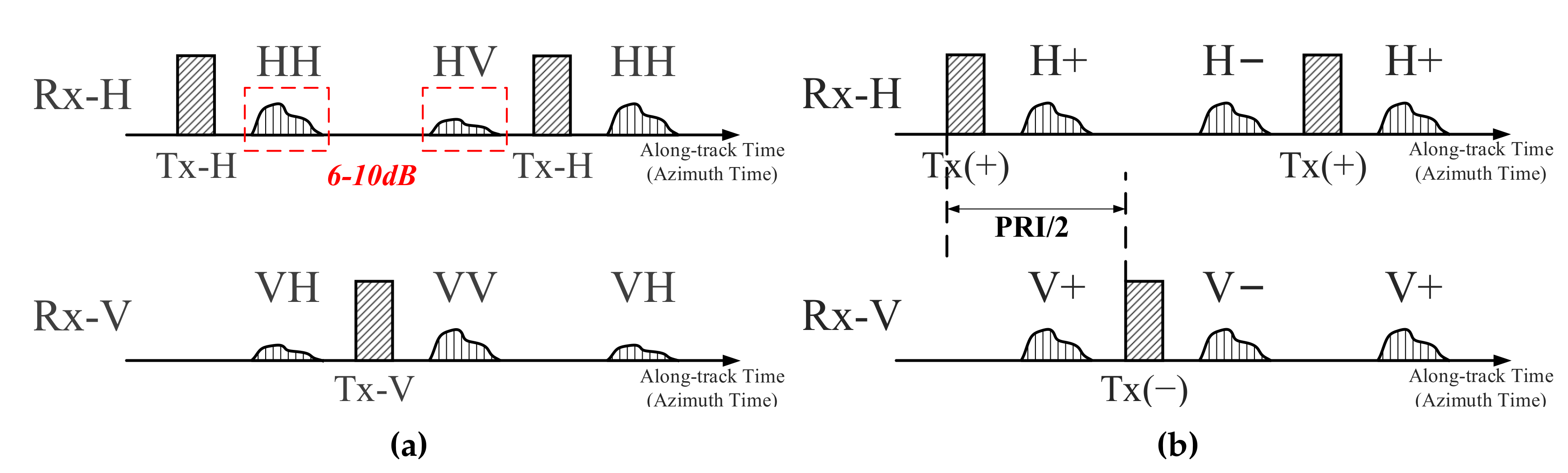
Note that H and V are unit vectors with identical transmitting power in Equation (1). Particularly, the polarization mode can switch to be circular-polarized when equals [4], and -polarized when [3]. Then polarimetric systems based on this hybrid mode receive echoes through H and V polarized channels simultaneously. As a contrast, conventional quad-pol SAR systems transmit H and V polarized waves alternately, and receive echoes through H and V polarizations simultaneously. Figure 1 shows the timing diagram of the conventional quad-pol mode and hybrid quad-pol mode for transmitted signals and received echoes.
Echoes in hybrid quad-pol SAR can be listed in a scattering matrix as Equation (2).
The range ambiguities arise from undesired echoes of adjacent pulses. In conventional quad-pol SAR, desired cross-pol echoes (HV/VH) suffer from severe odd-order range ambiguities that come from stronger co-polarizations (HH/VV). From Figure 1 and Equation (2), it can be seen that the power of echoes (e.g., H+ and H−) from interleaved transmitted signals is balanced equivalently. And then the range ambiguity performance is balanced [5,8].
- Signal Analysis & Azimuth Ambiguity in Hybrid Quad-pol Mode
For hybrid quad-pol SAR, the main purpose is to obtain the four polarized data under conventional linear polarimetric bases, i.e., HH/HV/VH/VV, from the acquired hybrid data, see Equation (2).
In Equation (2), no matter what the is, pulses of V polarized transmission have a fixed modulated phase of 0 or alternately (e.g., the HV expression in and ). Similar to the principle of azimuth phase coding (APC) technique in [16], alternate phase modulation of 0 and , i.e., phase modulation of , brings a spectrum shift in Doppler frequency domain, which is equal to here. Note that the is the pulse repetition frequency of any single transmitting channel (+ or −) in Equation (1). The total pulse repetition frequency here in this mode is , see Figure 1.
Take H-polarized receiving channel as example. In hybrid quad-pol mode, echoes of H+ and H− can be acquired. When time sequence is considered, they can be expressed as below:
According to signal structure of hybrid quad-pol mode in Equation (1), echo pulses of the H-polarized receiving channel can be derived as
Note that , i.e., Equation (4), represents all echoes acquired from H polarized receiving channel. It is sampled at .
Spectrum of Equation (4) can then be then derived as
Analogously, the spectrum of the whole echoes from V polarized receiving channel can also be derived:
When observed with antenna pattern and azimuth ambiguity, the Doppler spectrum of pulses in H polarized receiving channel can be drawn and displayed in Figure 2.
In Equations (5) and (6), there is an extra spectrum shift of in signals of V polarized transmission, i.e., in Equation (5) and in Equation (6). With the sampling frequency, this means that the spectra of and from H polarized receiving channel are staggered along Doppler frequency with a shift of . The same goes for the components of and from V polarized receiving channel.
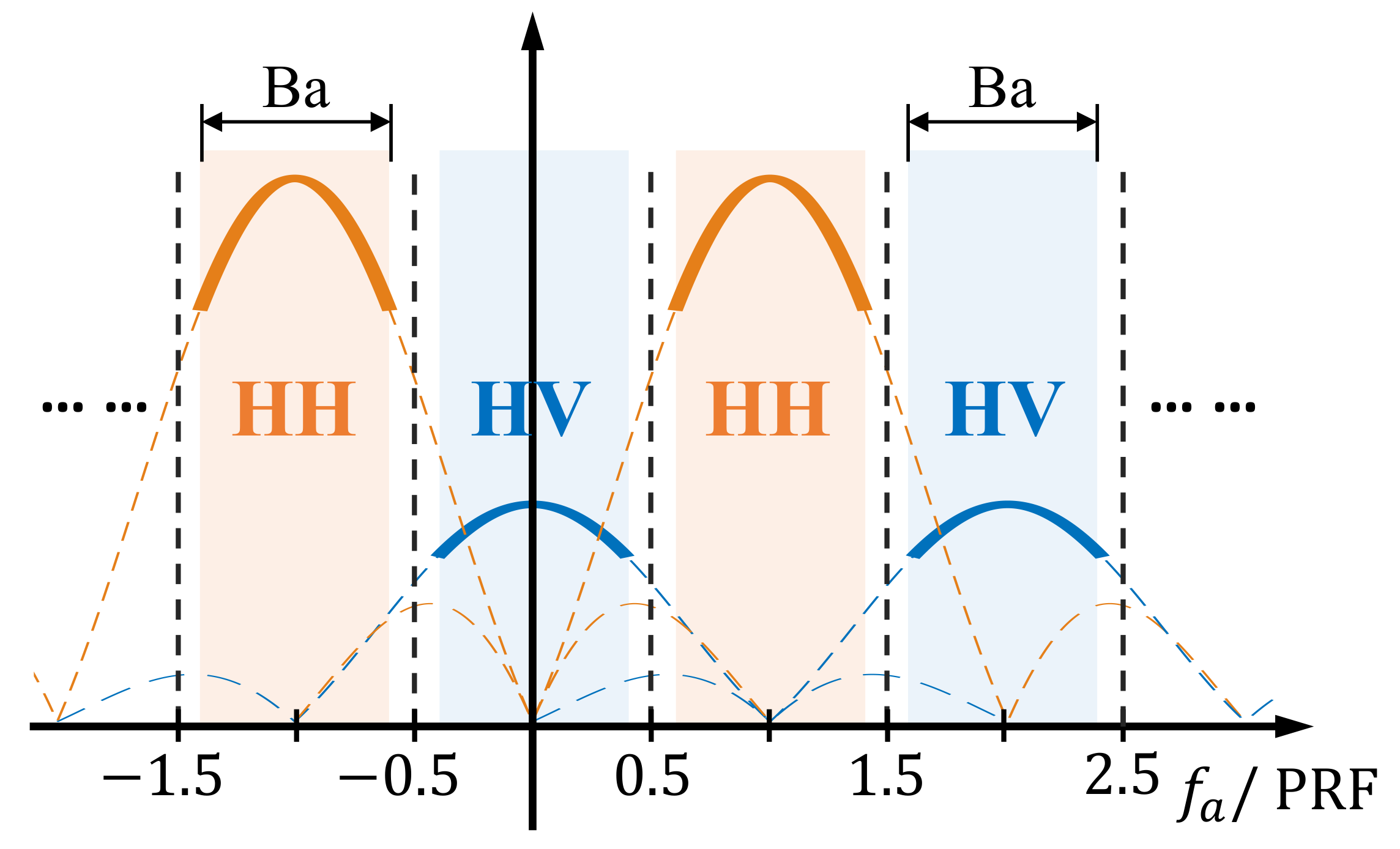
Still take H polarized receiving channel as example. Figure 2 shows the spectrum distribution of and . The main lobe of the HV polarized spectrum locates at , while the spectrum of HH polarized part shifts along the Doppler frequency axis for .
Therefore and can be perfectly separated through azimuthal spectrum filtering when desired parts are considered (bold solid lines marked with two different colors in Figure 2). For instance, the HH components can be reserved if the HV components are filtered out and vice versa. This means that the two different polarized echoes in one receiving channel, i.e., and in or and in , can be divided.
Note that this azimuthal spectrum filter is implemented in Doppler spectrum only and will not influence the cross-track (range) spectrum. This operation is independent of cross-track (range) direction and will not influence cross-track signals no matter what the signals are.
- Composition of azimuth ambiguities in hybrid quad-pol data
In Figure 2, spectra of HH and HV polarizations (marked with orange and blue respectively) are displayed with azimuth ambiguities considered. The dashed lines represent the undesired azimuth ambiguities. It is clearly seen that azimuth ambiguities of HH polarization contaminate HV signals while azimuth ambiguities of HV polarization contaminate HH signals.
Through azimuthal spectrum filtering, spectra of HH and HV polarized signals can be reconstructed as below (phase term is ignored for simplicity here):
and
where the hat on means the undesired ambiguities. represents the antenna pattern weighting ratio between the mth ambiguity and the desired signal.
Generally, echo power of co-polarizations (HH and VV) is stronger (usually 6–10 ) than that of cross-polarizations (HV and VH). Therefore, in hybrid quad-pol mode, the azimuth ambiguity performance will deteriorate in cross-pol channels and meliorate in co-pol channels with the transposition of odd azimuth ambiguities from Equations (7) and (8). Consequently, ambiguity performance of acquired co-pol channels is fine. The main purpose of this paper is to remove the strong co-pol azimuth ambiguities in cross-pol channels.
2.2. Azimuth Ambiguity Suppression Method Based on Dfpp and Waveform Diversity
In order to solve the problem of poor imaging quality caused by strong azimuth ambiguous signals in cross-pol channels, we developed an azimuth ambiguity suppression method aimed at odd-order azimuth ambiguous signals.
Obviously, one mainstream idea for suppressing or dislodging the unneeded components from the desired data is to find the “difference” between the undesired and the desired, and then make proper use of the “difference”. As a potential method for suppressing range ambiguities, “orthogonal” or pseudo “orthogonal” waveforms has been proposed in the last few decades, such as up/down (positive/negative) chirp signals [17] and orthogonally paired nonlinear frequency modulated (NLFM) signals. However, this method has a limitation of generating the defocused “clutter” if the signals are directly used.
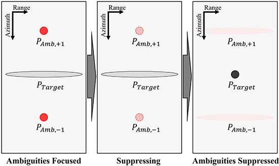
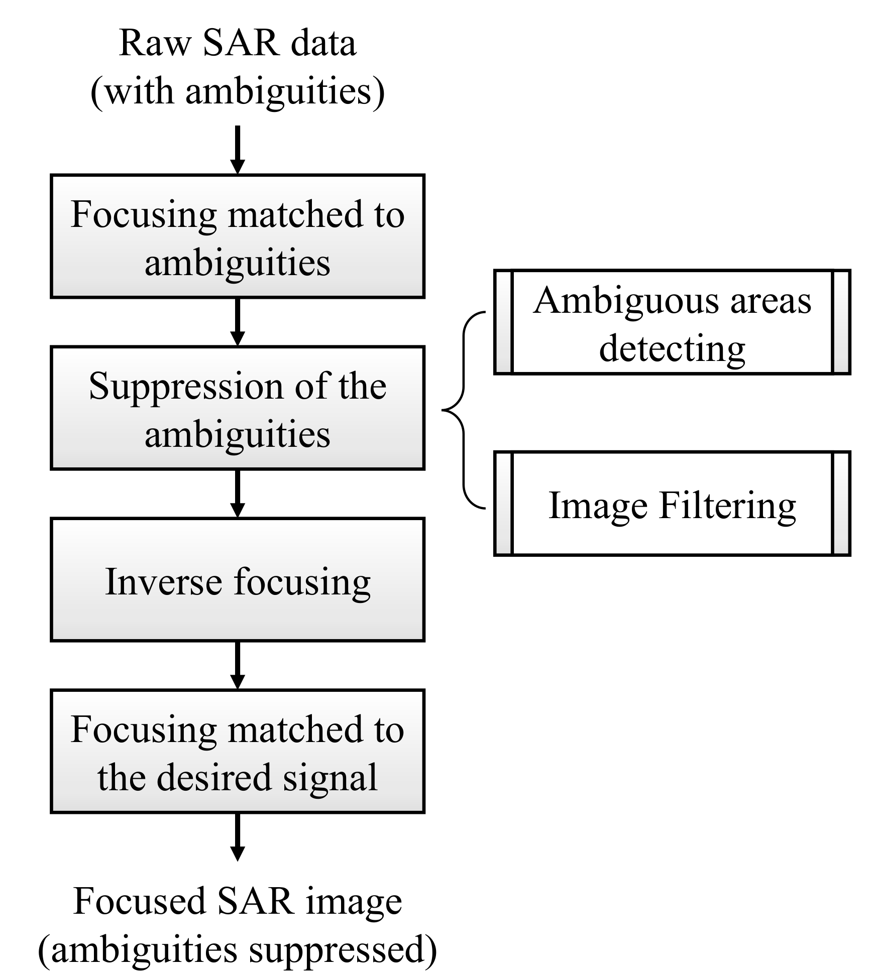
In [15], a dual-focus post-processing (DFPP) idea is applied to handle the nadir echo influence. Similarly, it is also used in suppressing the range ambiguities [14]. The procedure is briefly shown in Figure 3: focusing the undesired part firstly, detecting and removing the focused part afterwards, and at last refocusing the desired images.
Two different waveforms are applied in alternate transmission to form the “difference” between the desired and the undesired parts. The signal configuration of transmission is shown as Equation (9).
where n is the sequence number of the transmitted pulses and means fast time in the range (cross-track) direction; signal waveforms and can be set as up and down chirps or other similar waveform pairs with weak cross-correlation. Then the odd-order range ambiguities are distinguishable from the desired main echoes by the different signal waveforms [14].
- Signal form using DFPP technique
Different with nadir echoes or range ambiguities that originate from multiple unneeded echoes before or after the desired echo, azimuth ambiguities are generated due to under-sampling of out-of-band signals [1]. Moreover, the dominating low-order azimuth ambiguities have similar imaging features to the desired targets. They are usually called “ghosts”, i.e., false targets.
From the polarization synthesis result in Section 2.1, simply applying the signal configuration of Equation (9) to hybrid quad-pol mode is helpless in suppressing the azimuth ambiguities. This is because the polarizations of the transmitted signals are hybrid, which leads to the hybrid of polarizations in azimuth ambiguities. The alternation of waveforms in Equation (9) would not alter the signal waveform of the azimuth ambiguities.
In hybrid quad-pol mode, the odd-order azimuth ambiguities in cross-polarization and co-polarization after polarization synthesis are swapped with each other, see Equations (7) and (8) in Section 2.1. Therefore, the diverse waveforms can be configured in different polarizations, such as HH to HV and VH to VV. To meet this requirement, the H and V polarized pulses in transmission Equation (1) can be set with diverse waveforms respectively. The new configuration of the waveforms can be set as Equation (10).
where means transmitting signal of x polarization, the subscripts of and represent the corresponding transmitting channels.
According to Section 2.1, the mixed signals of co-polarization and cross-polarization in the same receiving channel can be separated through azimuthal spectrum filtering. This filtering method is independent of cross-track (range) direction and will not be influenced if the signal waveform changes. Take H polarized receiving channel as example. Like Equations (7) and (8), the acquired HH and HV signals synthesized by hybrid quad-pol data with the new configuration applied turn to be
and
- Focusing of the ambiguities
In Equations (11) and (12), the odd-order azimuth ambiguities own different signal waveforms to the desired main signals. Following the DFPP processing procedure, filters matched to the undesired odd-order azimuth ambiguities can be then applied to the synthesized signals.
For HV channel, i.e. Equation (12), this filter is set as
where the is complex conjugate operation, FFT is the fast Fourier transform. After frequency filtering using Equation (13), the undesired HH polarized azimuth ambiguities are focused, whereas the desired main HV polarized signals are smeared.
Analogously, the ambiguity-matched filter to the other cross-polarization VH should be matched to the waveform of V polarized transmission, i.e., , here [see (10)].
- Suppression of the ambiguities
After imaging of the ambiguities, the azimuth ambiguities can be then suppressed through the detection and removing procedure. Moreover, owing to the remarkably stronger power of co-polarizations compared to cross-polarizations, the detection of the undesired co-polarized azimuth ambiguities in cross-pol channels is much easier than the detection of range ambiguities in [14,15].
- Inverse focusing & Re-imaging
According to the reversible imaging process, echo data can be obtained through anti-compression in range and azimuth direction. The inverse imaging process is applied after the detection and removing of the focused ambiguous areas.
At last, through imaging process using the filter matched to the desired main signal, the final images with suppressed ambiguities are obtained.
Note that in co-polarizations of HH and VV, this azimuth ambiguity suppressing method is unnecessary. This is because the major influence in co-pol channels comes from odd-order azimuth ambiguities of cross-polarizations with weaker power [see Equation (11)]. Furthermore, the defocusing property induced by waveform mismatch gives rise to the dispersed energy of the odd-order azimuth ambiguities for all the reconstructed channels. This also helps to further improve the image quality in co-polarizations.
3. Result
3.1. Simulation
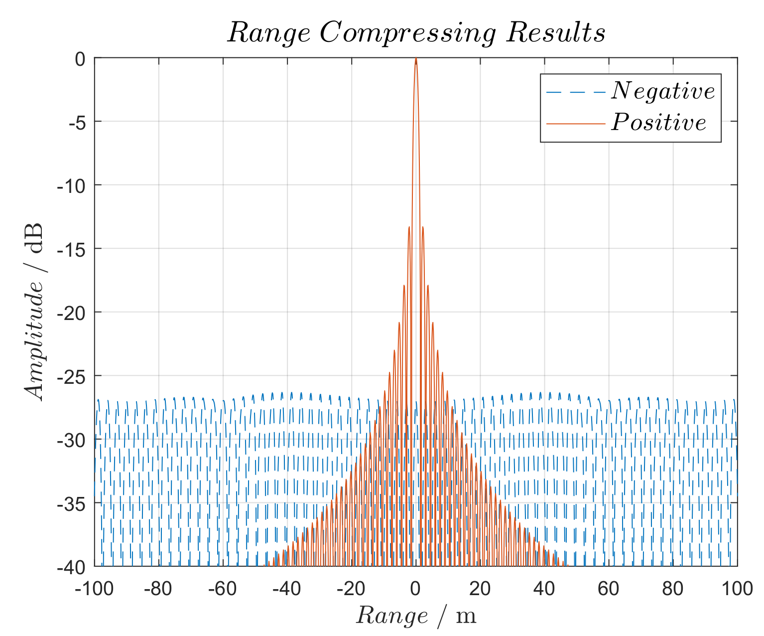
In this paper, up and down modulated chirps are chosen in the proposed ambiguity suppression method. Note that as a result of waveform mismatch, the smear occurs in the range direction if up and down chirps are applied. Figure 4 briefly shows the results of pulse compression under matched and mismatched filters.
Using the system parameters provided in Table 1, the azimuth ambiguity suppression results are presented with a simulation. A set of sea-surface polarimetric complex data of quad-pol mode acquired by Gaofen-3 SAR sensor is applied to simulate the hybrid quad-pol data using waveforms of up and down modulated chirps.
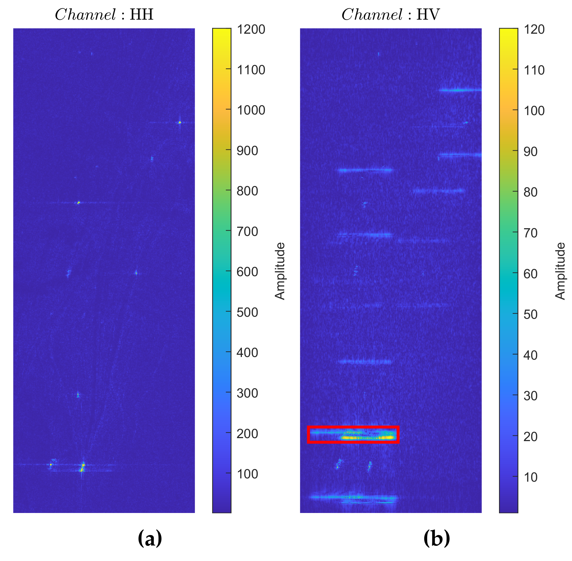
In Figure 5 and Figure 6 are generated after polarization synthesis using azimuthal spectrum filter. In Figure 5, it is distinct that the cross-pol HV channel suffers from severe azimuth ambiguities whereas co-pol HH channel is exempt due to weaker power of HV polarization. Meanwhile, with the waveforms of up and down chirps applied, the HH azimuth ambiguities are smeared due to waveform mismatch [see Figure 5b].
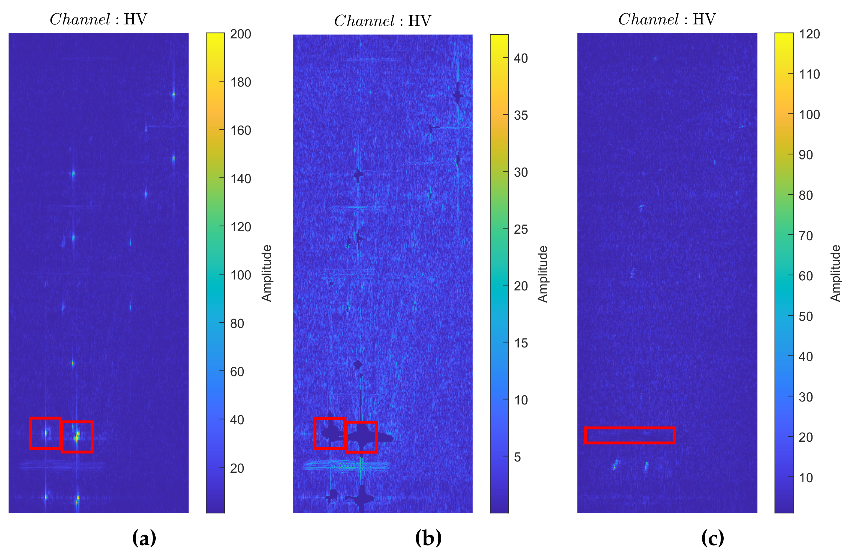
Figure 6 displays the procedure of eliminating the azimuth ambiguities in cross-pol HV channel using method of DFPP (co-pol channels are not seriously affected [see Figure 5a]). In Figure 6a, the originally acquired HV raw data are compressed using filter matched to HH azimuth ambiguities. The desired HV component is smeared in the range direction, whereas the HH odd-order azimuth ambiguities are focused.
These focused strong HH azimuth ambiguities are then removed [see Figure 7b]. Due to the polarimetric feature of stronger power in co-polarizations, the removing process is simply realized here by setting several pixels to zero according to an adaptive threshold (based on local contrast minimization). Other advanced methods such as Constant False Alarm Rate (CFAR) detecting method can also be considered for better results.
At last, the image is handled by inverse imaging process. The acquired new HV raw data are then re-focused as Figure 6c using corresponding filter matched to the desired HV signal.
Compare the figures marked with red rectangles in Figure 5 and Figure 6. It is shown that the azimuth ambiguities (smeared in Figure 5b and focused in Figure 6a) are removed effectively (Figure 6c). It indicates that the ambiguity signal power in data has been well suppressed and the effect of ambiguity suppression is remarkable. The result shows the accuracy and validity of the proposed ambiguity suppression algorithm.
3.2. Performance Evaluation
- Analysis of the Result
In order for a particular performance evaluation, we analyze the suppressed ambiguities with statistical energy method. The main concept of this method is to compute the total energy of the originally introduced azimuth ambiguities and the total energy of the suppressed azimuth ambiguities, and to make a comparison. Generally, the energy can be obtained by calculating the sum of the squares of the pixels’ amplitude:
where is the amplitude of the pixel in the image; is calculated for extracting the undesired azimuth ambiguities via subtraction of the original image data from the ambiguity-contaminated image data.
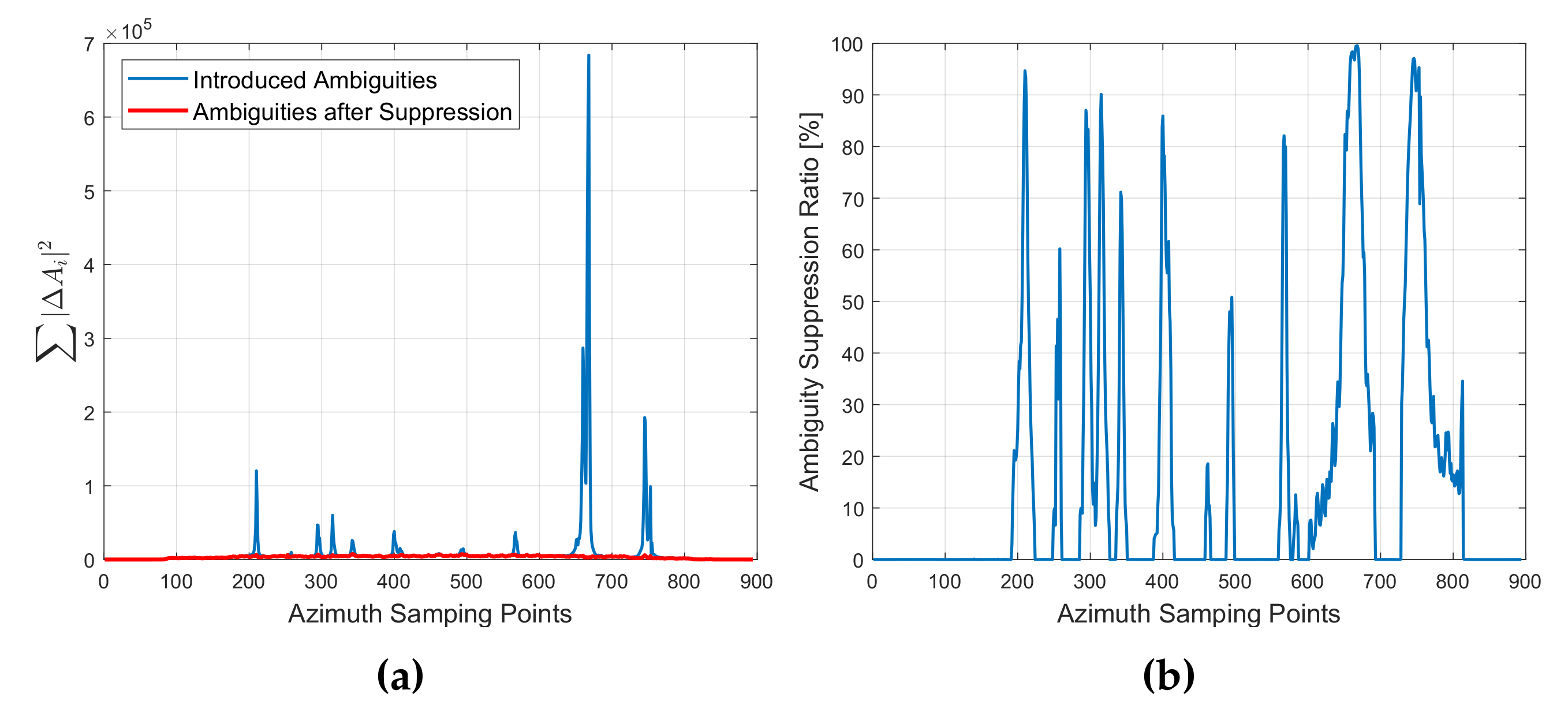
Taking the azimuth sampling time as the X-axis, the total energy as the Y-axis, we can draw the curves in Figure 7.
From Figure 7, it can be found that most of the strong azimuth ambiguities are well suppressed. Furthermore, the suppression effectiveness is closely related to the energy of the ambiguities. When the energy of the focused ambiguity (see Figure 6a) is stronger than the preset adaptive threshold, the suppression result is fine, up to , e.g. ambiguities with statistical energy larger that in Figure 7a are well suppressed. As to the other ambiguities which are weaker than the threshold, the stronger the ambiguities are, the better the suppression effect is. From this phenomenon, We can make a reasonable conjecture that the suppression effectiveness of the proposed method could deteriorate in images with low SNR, as the relatively weak ambiguities would be scattered and submerged in the noise. However, in consideration of the ambiguity defocusing induced by waveform diversity, the proposed ambiguity-suppression method is still effective.
- Result Analysis with various SNRs
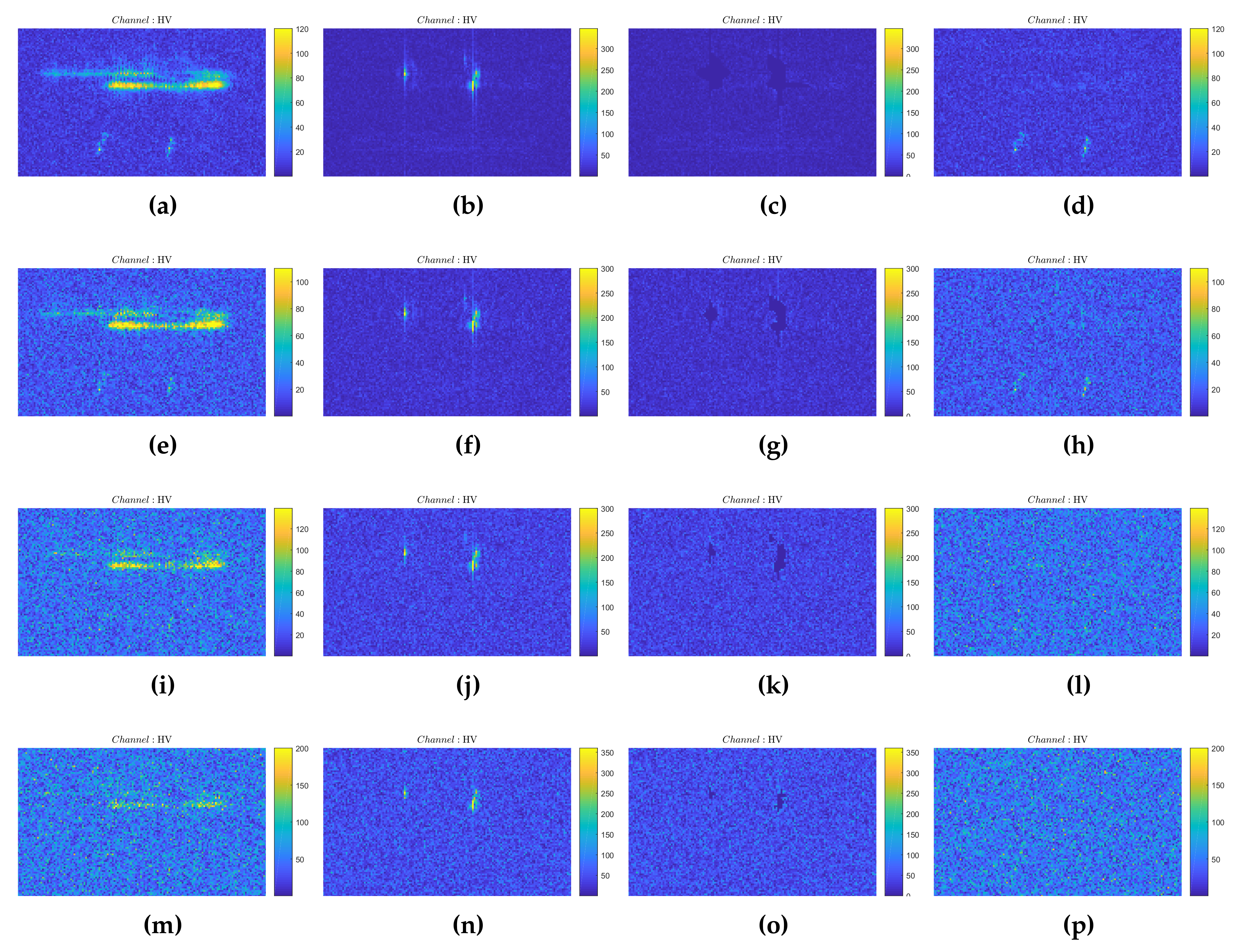
In the above experiment, the SNR of the desired HV polarized targets to the background noise in Figure 6c is approximately . The corresponding azimuth ambiguities are marked with red rectangle in Figure 6c. Using the proposed method, the results of the ambiguity-suppression performance of the two targets are (left target, T1) and (right target, T2). Simulations under varied SNRs are carried out then. The results are displayed in Figure 8.
In Figure 8, the results are simulated with SNRs of , , and . Comparing figures in the third column, we can find that the suppressed part of the azimuth ambiguities decreases due to the reduced SNR. This means a gradually weakened trend of the suppression performance. At the same time, figures in the fourth column show the deterioration of the image quality when the SNR is reduced.
It is not difficult to find that even in low SNR situations where the desired HV targets are nearly submerged in noise the proposed method works well [see Figure 8i,l,m,p]. This is because the strong power of co-polarizations helps the detection procedure in this method. Moreover, the azimuth ambiguities can be detected and suppressed much more easily as they are focused (see figures in the second column).
The suppression performance with different SNRs is also evaluated. The results are presented in Table 2.
In Table 2, the suppression performance results with SNRs under are also listed. Note that this method also takes some effect even when the SNR is extremely low. This arises from the power difference between co- and cross- polarizations. In addition, the undesired HH polarized ambiguities are mainly focused to be several strong pixels in the images. This also helps the detecting of the ambiguities.
However, the suppression performance is not very fine when the noise intensity increases greatly. The detectable part of the focused ambiguities decreases gradually when the SNR is reduced [see Figure 8c,g,k,o]. From Table 2, the suppression performance is degraded as with SNR of . Note that the image quality of the original cross-polarized images would extremely deteriorate in situations with extremely low SNR (e.g., the desired HV polarized targets in Figure 8m,o are already submerged, where the SNR is ). Therefore, the proposed method is still functional.
- Calculation Performance Evaluation
As is described in Section 2.2, the proposed method contains four steps: (1) imaging of the ambiguities, (2) detection and suppression of the ambiguities, (3) inverse imaging and (4) imaging of the desired signals.
Generally, for spaceborne SAR data, imaging is a time-consuming signal-processing step. While the step of detection and suppression could be less complex as it is based chiefly on 2-dimensional image processing. The total processing time can be summarized as
4. Discussion
For the originally proposed hybrid quad-pol SAR systems, the linear polarizations or the left/right circular polarizations are adopted. The ’hybrid’ feature helps balance the range ambiguity performance among quad-pol channels after the polarization synthesis from hybrid polarimetric bases to conventional quad-pol bases. As is introduced above, the proposed azimuth ambiguity suppression method combines two different signals to generate the transmitting ’hybrid’ polarizations. This means that the hybrid signals in transmission are not entirely linear or circular polarizations here.
Nevertheless, this method is still feasible if the purpose is to obtain the four linearly polarized data, i.e. HH/HV/VH/VV. According to the analyses of the hybrid quad-pol signals in Section 2.1, both the received signals in H and V polarized receiving channels can be divided into individual polarized signals through azimuthal spectrum filtering without influence on range direction [Figure 2, see Equations (4) and (5)]. Moreover, according to the uniqueness theorem for electromagnetic field, it does not influence the polarimetric scattering characteristics.
To be specific, HH and HV signals in H polarized receiving channel (or VH and VV signals in V polarized receiving channel) are separable. The acquired signals are then compressed through cross-track pulse compression using corresponding filters in imaging process, where the waveforms are compressed and the range resolution information remains. This indicates that the proposed ambiguity suppression method is feasible.
Note that this method can only eliminate the odd-order azimuth ambiguities, as the even-order components have the same signal form as the desired “zero-order” signal. Moreover, example in Figure 6 focuses on azimuth ambiguities of strong independent targets. When it comes to large scenes with moderate contrast, using filter matched to the odd-order ambiguities, the azimuth ambiguities will be focused as a whole scene superimposed by the smeared desired signals. In this situation, the azimuth ambiguities are partly removed (ambiguities with stronger energy can be suppressed according to the preset threshold). Furthermore, with regard to scenes with crowed strong independent targets (e.g. in a busy shipping lane), application of this method could also be limited. In this situation, some targets may be unfortunately spaced at the interval between azimuth ambiguities, which could influence the detection result. Therefore, this method may not be suitable for suppressing azimuth ambiguities of large flat scenes as well as scenes with crowed strong targets.
5. Conclusions
In this paper, a new method of suppressing the azimuth ambiguities in hybrid quad-pol mode is proposed. This method exploits waveform diversity to establish the pulse-compression difference between desired signal and the odd-order azimuth ambiguities. The difference is then utilized to separate the azimuth ambiguities from the desired signal under dual-focus post-processing technique, in which the undesired ambiguities can be focused and removed individually. Its effectiveness and correctness are verified by processing polarimetric imaging simulation based on hybrid quad-pol SAR architecture. Therefore, the proposed method can be viewed as an alternative way to improve the image quality for hybrid quad-pol images. Note that this azimuth ambiguity suppression method performs well in scenes that suffers from strong false targets (such as sea surface with ships, bare land with buildings), and may be not suitable for scenes with averaged image intensity (such as large flat grassland and forest) and scenes with crowed strong independent targets. Further investigations are also needed in other potential ways to improve the ambiguity suppression method.
Author Contributions
Conceptualization, P.Z.; Methodology, P.Z.; Software, P.Z.; Validation, P.Z. and W.W.; Formal Analysis, P.Z. and W.W.; Investigation, P.Z.; Resources, Y.D. and R.W.; Data Curation, P.Z.; Writing-Original Draft Preparation, P.Z.; Writing-Review and Editing, Y.D., W.W., D.L. and R.W.; Visualization, P.Z.; Supervision, Y.D. and R.W.; Project Administration, Y.D.; Funding Acquisition, Y.D. and R.W. All authors have read and agreed to the published version of the manuscript.
Funding
This work was funded by the National Science Fund for Distinguished Young Scholars Grant No. 61825106, and by the National Natural Science Foundation of China Grant No. 61701479 and 61971401.
Acknowledgments
We are thankful to the four anonymous reviewers for the constructive suggestion of including a more detailed performance analysis.
Conflicts of Interest
The authors declare no conflict of interest.
References
- Cumming, I.G.; Wong, F.H. Digital Processing of Synthetic Aperture Radar Data: Algorithms and Implementation; Artech House: Norwood, MA, USA, 2005. [Google Scholar]
- Lee, J.S.; Pottier, E. Polarimetric Radar Imaging: From Basics to Applications; CRC Press: Boca Raton, FL, USA, 2009. [Google Scholar]
- Souyris, J.C.; Imbo, P.; Fjortoft, R.; Sandra, M.; Jong-Sen, L. Compact polarimetry based on symmetry properties of geophysical media: The pi/4 mode. IEEE Trans. Geosci. Remote Sens. 2005, 43, 634–646. [Google Scholar] [CrossRef]
- Raney, R.K. Hybrid-Polarity SAR Architecture. IEEE Trans. Geosci. Remote Sens. 2007, 45, 3397–3404. [Google Scholar] [CrossRef] [Green Version]
- Raney, R.K.; Freeman, A.; Jordan, R.L. Improved Range Ambiguity Performance in Quad-Pol SAR. IEEE Trans. Geosci. Remote Sens. 2012, 50, 349–356. [Google Scholar] [CrossRef]
- Ainsworth, T.L.; Kelly, J.P.; Lee, J.S. Classification comparisons between dual-pol, compact polarimetric and quad-pol SAR imagery. ISPRS J. Photogramm. Remote Sens. 2009, 64, 464–471. [Google Scholar] [CrossRef]
- Raney, R.K. Comparing Compact and Quadrature Polarimetric SAR Performance. IEEE Geosci. Remote Sens. Lett. 2016, 13, 861–864. [Google Scholar] [CrossRef]
- Villano, M.; Krieger, G.; Moreira, A. New Insights Into Ambiguities in Quad-Pol SAR. IEEE Trans. Geosci. Remote Sens. 2017, 55, 3287–3308. [Google Scholar] [CrossRef]
- Moreira, A. Suppressing the azimuth ambiguities in synthetic aperture radar images. IEEE Trans. Geosci. Remote Sens. 1993, 31, 885–895. [Google Scholar] [CrossRef]
- Guarnieri, A.M. Adaptive removal of azimuth ambiguities in SAR images. IEEE Trans. Geosci. Remote Sens. 2005, 43, 625–633. [Google Scholar] [CrossRef]
- Di Martino, G.; Iodice, A.; Riccio, D.; Ruello, G. Filtering of Azimuth Ambiguity in Stripmap Synthetic Aperture Radar Images. IEEE J. Sel. Top. Appl. Earth Observ. Remote Ses. 2014, 7, 3967–3978. [Google Scholar] [CrossRef] [Green Version]
- Tao, Z.; Armando, M.; Weilin, Z.; Huilin, X. An Azimuth ambiguities removal method based on Polarimetric Notch Filter. In Proceedings of the 2017 IEEE International Geoscience and Remote Sensing Symposium (IGARSS), Fort Worth, TX, USA, 23–28 July 2017. [Google Scholar]
- Gebert, N.; Krieger, G.; Moreira, A. Digital Beamforming on Receive: Techniques and Optimization Strategies for High-Resolution Wide-Swath SAR Imaging. IEEE Trans. Geosci. Remote Sens. 2009, 45, 564–592. [Google Scholar] [CrossRef] [Green Version]
- Wen, X.; Qiu, X.; Han, B.; Ding, C.; Lei, B.; Chen, Q. A Range Ambiguity Suppression Processing Method for Spaceborne SAR with Up and Down Chirp Modulation. Sensors 2018, 18, 1454. [Google Scholar] [CrossRef] [PubMed] [Green Version]
- Villano, M.; Krieger, G.; Moreira, A. Nadir Echo Removal in Synthetic Aperture Radar via Waveform Diversity and Dual-Focus Postprocessing. IEEE Geosci. Remote Sens. Lett. 2018, 15, 1–5. [Google Scholar] [CrossRef]
- Dall, J.; Kusk, A. Azimuth phase coding for range ambiguity suppression in SAR. Proc. IGARSS 2004, 3, 1734–1737. [Google Scholar]
- Mittermayer, J.; Martinez, J.M. Analysis of range ambiguity suppression in SAR by up and down chirp modulation for point and distributed targets. In Proceedings of the IGARSS 2003. 2003 IEEE International Geoscience and Remote Sensing Symposium (IEEE Cat. No.03CH37477), Toulouse, France, 21–25 July 2003. [Google Scholar]
Figure 1.
Timing diagram for transmitted signal and received echo. (a) Conventional quad-pol SAR system. (b) Hybrid quad-pol SAR system.Tx/Rx indicates the transmission/reception of the signals; the tags of HH/HV/VH/VV and H+/H−/V+/V− indicate the received echoes. is pulse repetition interval and is the reciprocal of pulse repetition frequency ().

Figure 2.
Doppler spectrum of echoes from H polarized receiving channel in hybrid quad-pol SAR mode. The bold solid lines and the dashed lines represent the desired main signals and undesired azimuth ambiguities respectively. is the bandwidth of desired main lobe. is set equal to here; Power of HH polarization is set higher than power of HV polarization.

Figure 3.
Block diagram showing the processing steps of the DFPP technique for suppressing the ambiguities.
Figure 3.
Block diagram showing the processing steps of the DFPP technique for suppressing the ambiguities.

Figure 4.
Range compressing results of up (positive modulation rate) and down (negative modulation rate) chirps using filter matched to up chirp. Parameters are taken from Table 1. The orange solid line shows the matched compression result. Whereas the blue dashed line shows the smearing compression result with filter mismatched.

Figure 5.
Simulations of the acquired HH and HV polarized images after polarization synthesis from hybrid quad-pol data based on parameters in Table 1. The HV and HH polarized data are simulated using chirp signals of up and down modulation rates respectively. Vertical is the azimuth direction. (a) Rebuilt HH polarized image with HV azimuth ambiguities. (b) Rebuilt HV polarized image with HH azimuth ambiguities. An example of smeared azimuth ambiguity is marked with red rectangle.

Figure 6.
Simulations of the acquired HV polarized images with azimuth ambiguities of strong HH polarization based on parameters in Table 1. HH polarized data are simulated using chirp signals chirp of up modulated rate. HV polarized data are simulated using chirp signals chirp of down modulated rate. Vertical is the azimuth direction. (a) Acquired HV image using filter matched to up chirp, in which the desired HV polarized component is smeared with HH azimuth ambiguities focused (e.g., the focused targets in red rectangle). (b) Smeared HV image, in which the focused HH azimuth ambiguities has been removed by simply setting several pixels to zero according to the amplitude level in image (image sharpness and contrast). (c) Refocused HV image, which is obtained by focusing the inverse-focused data (after inverse imaging process), using corresponding filter matched to the down chirp. The content in red rectangle can be compared with that in Figure 5b, showing a decent ambiguity suppression efficiency.

Figure 7.
Comparison curves of the azimuth ambiguities before and after the suppression procedure. (a) Statistical total energy results: blue line, the introduced azimuth ambiguities; red line, the remaining azimuth ambiguities after suppression. X-axis represents the azimuth time with sampling points. Y-axis shows the statistical result based on Equation (15). (b) Calculated ratio of the suppressed energy to the total energy of the azimuth ambiguities. X-axis represents the azimuth time with sampling points. Y-axis shows the suppression ratio expressed as a percentage.

Figure 8.
Simulations of the acquired HV polarized images with azimuth ambiguities of strong HH polarization based on parameters in Table 1 under SNRs of (first row), (second row), (third row) and (fourth row). The selected HV polarized images are separated from the original images in Figure 5 and Figure 6, retaining the selected target area marked with red rectangles. Figures of (a,e,i,m) in the first column represent the focused HV images contaminated by HH ambiguities; the ambiguities of HH polarization are focused in figures of (b,f,j,n) in the second column, and then suppressed in (c,g,k,o) in the third column; through inverse-imaging, the final results are displayed in the fourth column.


Table 1.
Simulation Parameters.
| Parameter | Value |
|---|---|
| Orbital height | 755 |
| Carrier frequency | |
| Waveform bandwidth | 15 |
| Platform velocity | 7500 |
| Antenna size | 20 |
| Pulse length | 10 |
| Channel PRF | |
| Look angle |
Table 2.
Suppression Performance with varied SNRs.
| SNR (dB) | T1, Results (%) | T2, Results (%) |
|---|---|---|
| 28 | ||
| 20 | ||
| 15 | ||
| 10 | ||
| 6 | ||
| 4 | ||
| 2 |
© 2020 by the authors. Licensee MDPI, Basel, Switzerland. This article is an open access article distributed under the terms and conditions of the Creative Commons Attribution (CC BY) license (http://creativecommons.org/licenses/by/4.0/).
Share and Cite
MDPI and ACS Style
Zhao, P.; Deng, Y.; Wang, W.; Liu, D.; Wang, R. Azimuth Ambiguity Suppression for Hybrid Polarimetric Synthetic Aperture Radar via Waveform Diversity. Remote Sens. 2020, 12, 1226. https://doi.org/10.3390/rs12071226
AMA Style
Zhao P, Deng Y, Wang W, Liu D, Wang R. Azimuth Ambiguity Suppression for Hybrid Polarimetric Synthetic Aperture Radar via Waveform Diversity. Remote Sensing. 2020; 12(7):1226. https://doi.org/10.3390/rs12071226
Chicago/Turabian StyleZhao, Pengfei, Yunkai Deng, Wei Wang, Dacheng Liu, and Robert Wang. 2020. "Azimuth Ambiguity Suppression for Hybrid Polarimetric Synthetic Aperture Radar via Waveform Diversity" Remote Sensing 12, no. 7: 1226. https://doi.org/10.3390/rs12071226
Note that from the first issue of 2016, this journal uses article numbers instead of page numbers. See further details here.