Wearable Sensors for Human–Robot Walking Together
by
 , ,
, ,
Alessandra Moschetti
1 ,
,
Filippo Cavallo
1,*,
Dario Esposito
2,
Jacques Penders
3 and
Alessandro Di Nuovo
3
1
The BioRobotics Institute, Scuola Superiore Sant’Anna, 56025, Pontedera (PI), Italy
2
Co-Robotics srl, 56033 Capannoli (PI), Italy
3
Sheffield Robotics, Centre for Automation and Robotics Research, Sheffield Hallam University, Sheffield S1 1WB, UK
*
Author to whom correspondence should be addressed.
Robotics 2019, 8(2), 38; https://doi.org/10.3390/robotics8020038
Submission received: 5 February 2019
/
Revised: 30 April 2019
/
Accepted: 1 May 2019
/
Published: 15 May 2019
(This article belongs to the Special Issue Collaborative Mechatronics Systems)
Abstract
:Thanks to recent technological improvements that enable novel applications beyond the industrial context, there is growing interest in the use of robots in everyday life situations. To improve the acceptability of personal service robots, they should seamlessly interact with the users, understand their social signals and cues and respond appropriately. In this context, a few proposals were presented to make robots and humans navigate together naturally without explicit user control, but no final solution has been achieved yet. To make an advance toward this end, this paper proposes the use of wearable Inertial Measurement Units to improve the interaction between human and robot while walking together without physical links and with no restriction on the relative position between the human and the robot. We built a prototype system, experimented with 19 human participants in two different tasks, to provide real-time evaluation of gait parameters for a mobile robot moving together with a human, and studied the feasibility and the perceived usability by the participants. The results show the feasibility of the system, which obtained positive feedback from the users, giving valuable information for the development of a natural interaction system where the robot perceives human movements by means of wearable sensors.
1. Introduction
1.1. Social Robots and Human–Robot Interaction
Thanks to recent technology improvements, researchers have demonstrated that personal robots have the capability to serve people in different tasks, showing a clear potential to become part of our everyday life as helpers and companions. Personal robots can help people in daily living in several situations, as caregivers, teachers, assistants, and companions [1,2,3,4]. Therefore, the way robots move around in working and living places has attracted the interest of many research groups. Some have focused their attention on the use of robots in public places, such as museums [5] and shopping malls [6]. Others aimed at developing robotic systems to assist the elderly at home, helping them during daily living by bringing grocery shopping, reminding them about drug intake and appointments, and helping them walk [7,8]. Hu et al. [9] proposed a robotic nursing assistant to help nurses in the hospital, whereas Penders et al. [10] developed a swarm of robots to assist firefighters. Robots could also help blind people to safely move around different environments [11].
To be fully accepted, robots should be able to cope with persons in a natural way [12] or, in other words, robots should have the ability to interact with humans, understand their social signals and cues and respond appropriately to facilitate "natural" human–robot interaction (HRI). In this sense, Lin et al. proposed the concept of the assistance coordination on the cognitive level, which foresees the capability of an intelligent robot to understand when to provide assistance and what kind of assistance to provide. This highlights the importance to design and develop adaptive human–robot interaction solutions able to serve humans in a more appropriate manner, i.e., by dynamically adjusting the interaction with users and matching the demand of maintaining task performance [13]. Enhancing these robot capabilities means improving both acceptability and social abilities. Much of the recent research has focused on the interfaces for HRI aiming at improving the acceptability of novel technologies by increasing usability, as proposed by the Robot-Era project [14,15]. To increase the social ability, robot’s functionality, perception, and acceptability should, thus, be enhanced. To improve the perception abilities of robots, the use of external sensors, such as environmental sensors and wearable sensors, and other external resources can be considered [16,17].
1.2. Increase HRI: Sensors in Social Robotics
Nowadays, advances in the Internet of Things (IoT) [18] can extend social robot abilities in terms of perception of surrounding environments. The “Internet of Robotic Things”, which is the integration of IoT with Robotics, can increase the potentiality of robotics services in terms of HRI, collaborative robotics, social assistive robotics, etc., [19] extending the perception capabilities of the robot. Therefore, the robot could be aware of what the user is doing and interact properly with them.
Different solutions for “connecting” humans and robots during navigation have been proposed in the last years. For instance, a stick was proposed in [20] as a linker between the human and the robot used for guiding people, such as firefighters and blind people. In this case, the robot should navigate in front of the persons, choosing the safest path, such as a guide dog for blind people. People were able to follow the robot quite correctly, showing that the use of this kind of connection could be employed in situations where the user needs to be guided. However, the use of a stick to be held in the hand raised some issue in firefighters’ applications due to the no-hands-free approach [11].
To obtain a more adaptable HRI, laser range finders (LRF) have been used to extract human gait information. Speed, gait phases, step length, cadence, and leg orientation can be extracted from LRF data [21]. For instance, the speed of the subject and the position of the legs are evaluated in [22] to develop a cognitive behavior-based robot control system. In [23], data from a laser and from a camera are fused to obtain useful information to make the robot follow a certain person. In practice, the camera is used to recognize the user to be followed thanks to the color and edge features of the torso, while the laser is used to obtain the position of the person.
The use of wearable inertial measurements units (IMUs) has been introduced in combination with LRF to increase the obtained information. Wu et al. [24] combined kinematic information from the LRF mounted on the robot and an IMU worn by the user. User speed, orientation, and leg position were evaluated combining data coming from LRF and an IMU worn on the pelvis [21]. LRF and cameras, however, can have problems in tracking legs and the users in some specific situations, such as low visibility (e.g., presence of smoke [10]) and clothing (e.g., use of clothes that covers human legs [21]).
In this context, this work aims to provide the user with wearable sensors that allow them to move naturally with the robot with no need of physical linkers and overcoming issues linked to clothing or low visibility and with no restriction on the relative position between the human and the robot. Therefore, this paper aims to investigate the feasibility and perceived usability of the use of wearable IMUs, which can be easily integrated into shoes, to control robot navigation.
Real-time gait parameters, such as walking speed, stride length, and turning angle are evaluated to modulate the robot motion to create a more natural interaction between the robot and the user. The proposed system was tested in two different tasks: in the first, the robot follows the user by tracking movements via the information coming from the IMU; in the second, the robot leads the navigation and uses the information obtained by IMU to check and adapt to the user’s walking speed and direction. The analysis of these experiments provides useful insights on human–robot walking together and it will allow the development of a more complex interaction system where the robot perceives all human movements and interprets the behavior by means of wearable sensors.
The rest of the paper is organized as follows: Section 2 introduces the sensors and the algorithms used to extract the parameters from the human gait, the robot used in the experimentation and the control implemented, and the experimental protocols adopted. Section 3 analyses the results, finally Section 4 presents discussion and conclusion.
2. Materials and Methods
The experimental work was split into two parts. In the first part, we verified the accuracy of the system by comparing the walking information calculated by a reference vision system with the one derived from data of inertial sensors. In the second part, the sensors were tested in real time with a robot in an HRI scenario. This section describes the components of the system and the experimental protocol carried out to test the performance of the inertial sensors and real-time interaction.
2.1. SensFoot
The device used for the analysis of the human gait was the SensFoot, represented in Figure 1, which is a device composed of a nine-axis IMU to be worn on the foot instep. The inertial sensors are integrated into an INEMO-M1 board with dedicated STM32F103xE family microcontrollers (ARM 32-bit Cortex ™-M3 CPU, from ST Microelectronics, Milan, Italy) and includes an LSM303DLHC (6-axis geomagnetic module, set on 8 g and 4.7 gauss, ST Microelectronics, Milan, Italy) and L3G4200D (3-axis digital gyroscope, set on 2000 deg/s, ST Microelectronics, Milan, Italy) and I2C digital output. Data are collected and transmitted via a Bluetooth serial device (SPBT2632C1A Class 1 module) toward a generic control station. A small, rechargeable, and light Li-Ion battery supplies power to the device. Two SensFoots (one for each foot) were used in both the experiments.
2.2. Gait Parameters Extraction
Human walking is a periodic movement of each foot from one position of support to the next. It is, therefore, a cyclic pattern of movement repeated step after step. The gait cycle consists of two phases: a stance phase, where the foot is on the ground, and a swing phase, where the foot is no longer in contact with the ground [25]. The gait cycle can be further divided into four phases, namely stance, heel-off, swing, and heel-strike that ends with the foot flat on the ground again [26].
Many works have focused on the estimation of the spatiotemporal parameters of walking using inertial-based sensors [27]. Parameters that are often evaluated are [26,28]:
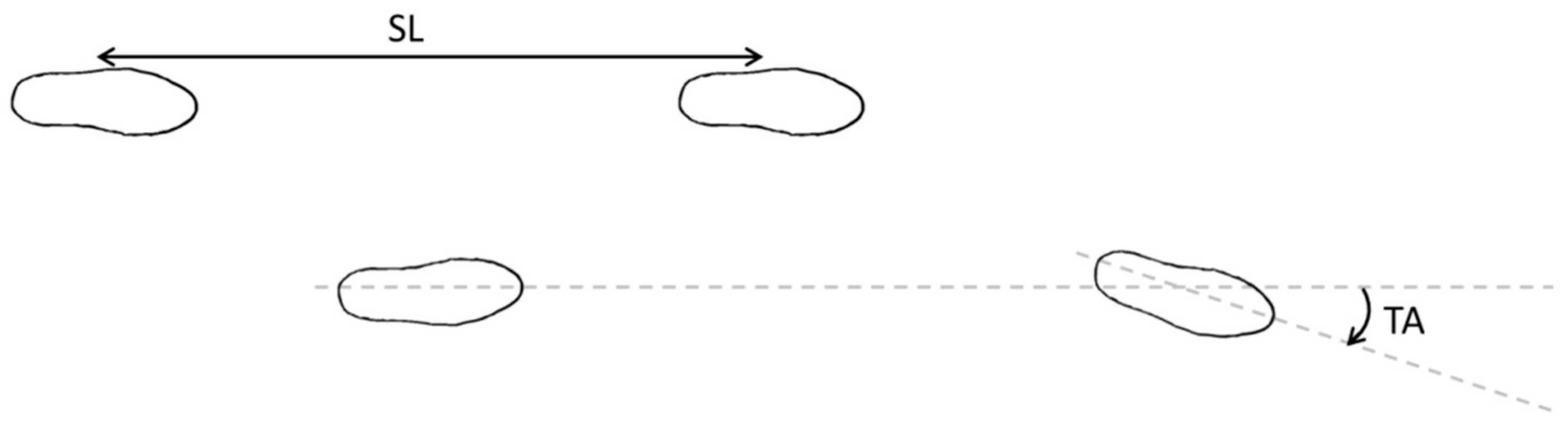
- Stride Length (SL): the distance between the reference point on one foot and the same point at two successive foot-flat positions (see Figure 2);
- Stride Time (ST): while walking, is the time between successive contacts of the same foot with the floor, i.e., the time for walking across the SL.
- Walking Speed (WS), it is calculated as the Stride Length divided by the Stride Time (SL/ST) [26];
- Foot Clearance (FC): is the maximum foot height during the swing phase;
- Turning Angle (TA): the change in azimuth between the beginning and end of the gait cycle (see Figure 2).
Several algorithms have been proposed in the scientific literature [29,30,31,32] with the aim to evaluate spatiotemporal parameters and extract the gait parameters listed above.
To evaluate the gait parameters, the SensFoots were placed on the instep of the feet, since, as shown in previous work [33], the application of the SensFoot in that position gave good results in terms of parameter extraction from the human gait. Moreover, in future applications, the sensor could be easily integrated into the shoe tongue or attached to the lace.
Basing on the chosen position, the segmentation of the gait cycle was made according to work by Sabatini et al. [26]. However, since Sabatini et al. [26] restricted the study to the analysis in the sagittal plane, thus, not considering a 3D approach, the algorithm proposed by the work of Mariani et al. [28] was also implemented. In this way, it was possible to evaluate the parameters and the walking trajectory required by the planned experimental tasks (see Section 2.3 and Section 2.4 for details).
In both [26] and [28] the theoretical procedure to evaluate step length and walking speed is similar, and it is composed of the following steps:
- Segmentation of the gait cycle into different phases;
- Evaluation of the initial orientation of the sensor;
- Update of the orientation at each time frame;
- Evaluation of a gravity-free component of acceleration in the fixed frame;
- De-drifted single and double integration of gravity-free acceleration to obtain speed and displacement.
In this work, to divide the gait cycle into phases, namely stance, heel-off, swing, heel-strike, and foot flat, the angular velocity of the foot on the sagittal plane was used according to [26]. These gait events were used to isolate each gait cycle and evaluate the parameters for each one.
Initial orientation of the sensor was obtained using the acceleration as an inclinometer. In practice, the initial quaternion was evaluated according to Favre et al. [34] and was used as the starting point for the quaternion-based time integration of the angular velocity. As a matter of fact, the 3D orientation of the sensor at each time frame was evaluated integrating the angular velocity [28] as explained in [34].
Once the orientation was known, the gravity-free components of the acceleration were computed at each time frame to finally evaluate the velocity and the displacement. The velocity was computed by trapezoidal integration of the acceleration [26,28]. Assuming zero velocity in the foot-flat period, the drift that affects the sensors has been removed by adopting a linear de-drifting [26]. The displacement components during each gait cycle were evaluated by integrating the velocity components.
The SL was computed by evaluating the distance between the position at the end of each gait (obtained by the displacements on each component) and the position at the beginning (that was set as zero). Finally, the turning angle was evaluated by computing the rotation between the initial and final orientation of each gait cycle on the azimuth [28].
In our experiments, the prototype system included two SensFoots to extract gait parameters from both feet. At each time frame, the orientation and the gravity-free acceleration were computed, while the stride length and the turning angle were calculated at the end of the gait cycle. Thus, the walking speed was computed by dividing the stride length by the time between two successive beginning of the gait, as shown in [26]. Data were collected at 50 Hz and then filtered with a second-order low-pass Butterworth filter with a cut-off frequency of 17 Hz for accelerometers or 15 Hz for gyroscopes [26].
2.3. Experiment I: Validation the Inertial Sensing Unit
The system used in this part of the work was composed of two SensFoots and an optoelectronic human motion analysis system SMART DX BTS (BTS Bioengineering Corp., Brooklyn, NY, USA), which was used to evaluate the results obtained from the IMUs. The BTS is composed of six cameras operating in the infrared range used to record human movements while markers (reflective points) are attached to the body at precise anatomical landmarks. The cameras capture the reflection of the markers and, thanks to a dedicated software, 3D reconstructions of the trajectories are obtained. In this way, it is possible to obtain all the parameters necessary to define the kinematics of the analyzed body part with an accuracy of 0.1 mm.
To evaluate the accuracy of the SensFoot and the implemented algorithms, nine persons, whose ages ranged from 24 to 31 (28.3 ± 2.6), were asked to walk on a platform (6 m × 1.5 m circa) following a U-shape path wearing SensFoots on both feet and optical markers. In practice, the optical markers were placed on the malleolus, on the hallux, and on the heel bone. The experiment was repeated twice, once in a clockwise direction and once in a counter-clockwise direction. In this way, it was possible to compare the parameters extracted with the SensFoot with the ones obtained by the BTS.
The SL, the TA, and the WS were evaluated both for the IMU and for the BTS. In analyzing the BTS data, the stride length was calculated as the distance covered by the foot optical marker between two consecutive foot-flat position. The walking speed was calculated by dividing the SL by the ST. Finally, the turning angle was evaluated as the angle between two markers segments in two consecutive foot-flat positions. The stride length and the walking speed were evaluated considering an artificial intermediate point between the markers on the hallux and on the malleolus, which corresponds to the position of the SensFoots. The turning angle was evaluated considering all the possible coupling of markers. Finally, the correlation, the absolute error, and its standard deviation were calculated.
2.4. Experiment II: Testing the HRI through SensFoots in Use-Case Scenarios
The second test consists of hands-on experimentation with human participants to simulate real use scenarios. For this HRI experiment, again two SensFoots were used as well as, the Pepper robot, and a processing module, which acquired data from the SensFoots, extracted significant parameters real-time and controlled the robot.
This experimental study received ethical approval from the committee of the Faculty of Arts, Computing, Engineering and Science, Sheffield Hallam University. All participants gave informed consent to use their data, seventeen out of nineteen gave consent to use video/audio recordings and pictures for scientific research purposes.
2.4.1. Pepper Robot
Pepper is a humanoid robot (see Figure 5) developed by SoftBank for social human–robot interaction [35]. It has three multi-directional wheels that enable it to move fluently around the environment [36]. The planar speed is set to 0.35 m/s, but it can be set up to a maximum of 0.55 m/s [37]. It is provided with an anti-collision system to detect people and obstacles and reduce the risk of collisions. Pepper is equipped with wireless connectivity. Moreover, it has a lithium-ion battery providing almost 12 h of autonomy.
The operating system running on the robot is a proprietary one, i.e., NAOqi. It offers a wide-ranging Application Programming Interface (API) that allows low-level methods, to manage sensors and motor units, and high-level methods to create more sophisticated behaviors. SoftBank provides also software development kit (SDK) for Python, C++, Java, and JavaScript [36]. In this work, a Python program was developed to manage the robot.
2.4.2. HRI Experimental Protocol
Nineteen healthy adult participants, 8 females and 11 males, whose ages range from 19 to 44 (28.3 ± 7.0) were involved in the HRI experimental sessions. The experiments were conducted in a large empty classroom with a clear area of 10.5 m2 for walking.
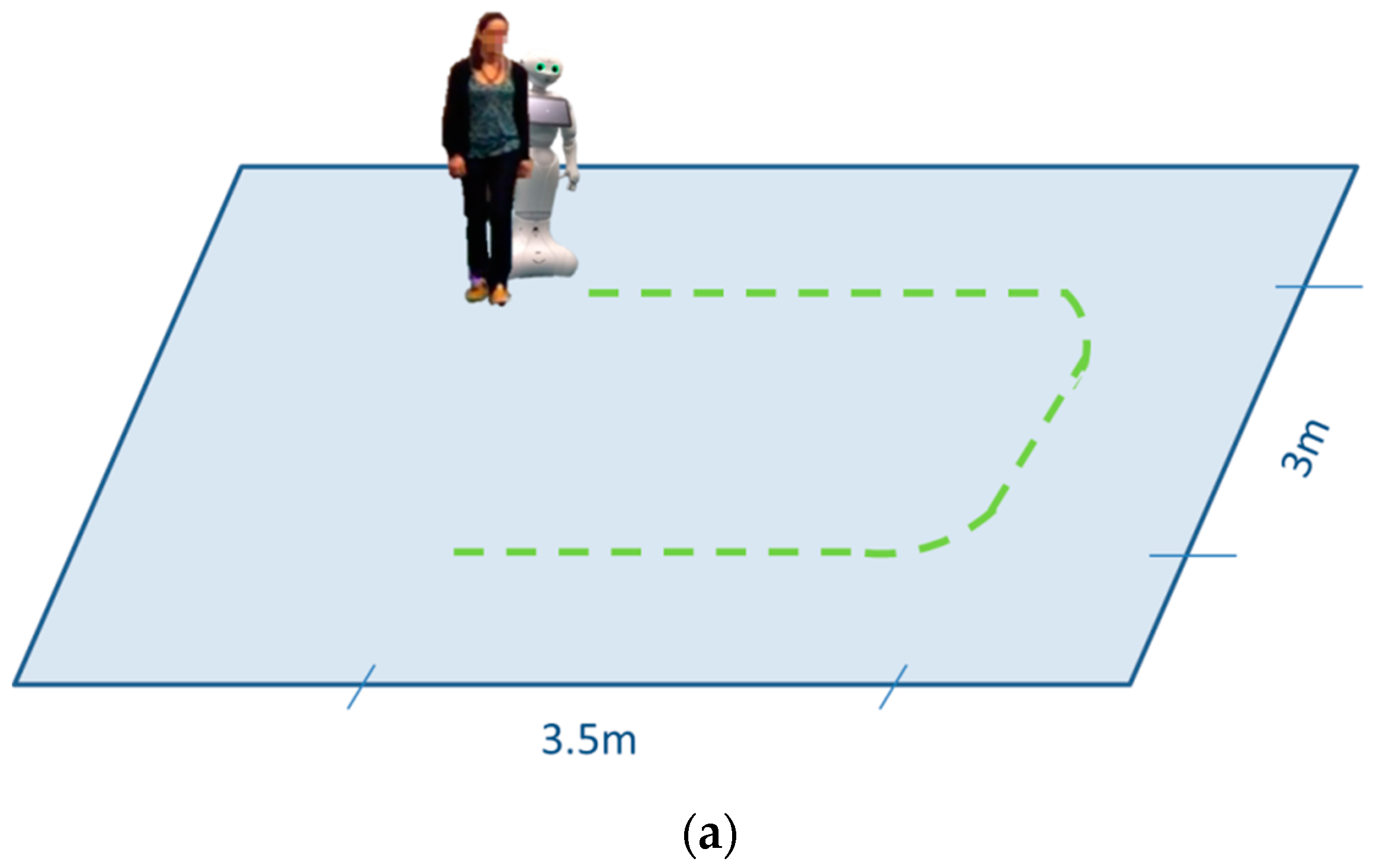
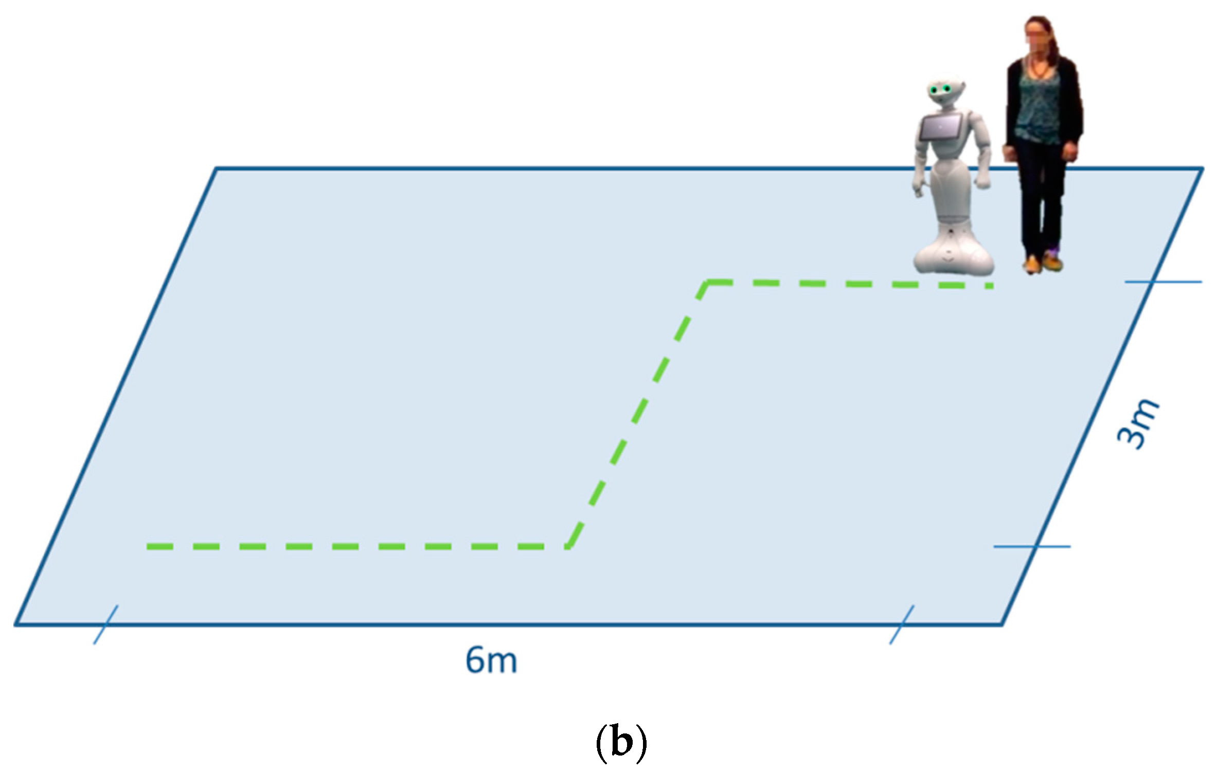
The system was tested in two tasks, i.e., the following task and the follow-me task. In the former, the robot had to follow the user, who was asked to begin the test next to the Pepper robot, then walk straight, make a U-turn toward the right and then walk straight again until the final position (see Figure 3a). In the latter, the user was asked to begin the task behind the robot and follow it around the room; no indication about the path was given to people even if the robot was programmed to always follow the same path (see Figure 3b). Figure 4 shows some pictures taken during the experimentation.
Before starting the experiment, the researcher verbally explained the tasks and provided the information sheet, which the participant signed after reading to confirm informed consent. While explaining the tasks, the researcher pointed out the path the participant had to follow in the following task to make all the participants aware and avoid mistakes. Preliminarily, the sensors were fitted to the participant shoe as shown in Figure 1.
Participants were asked for permission to be filmed during the experimentation to later analyze the video and evaluate the latency between the robot and the user. Seventeen out of nineteen persons consented to be filmed.
At the beginning of each task, the robot itself explained the task they had to perform. In this way, the user could also have a speech interaction with the robot (the robot asked whether the user understood the task and whether he/she was ready to start) and all the participants received the same explanation. At the end of both tests, participants were asked to fill out a questionnaire about their experience; the questionnaires were kept anonymous.
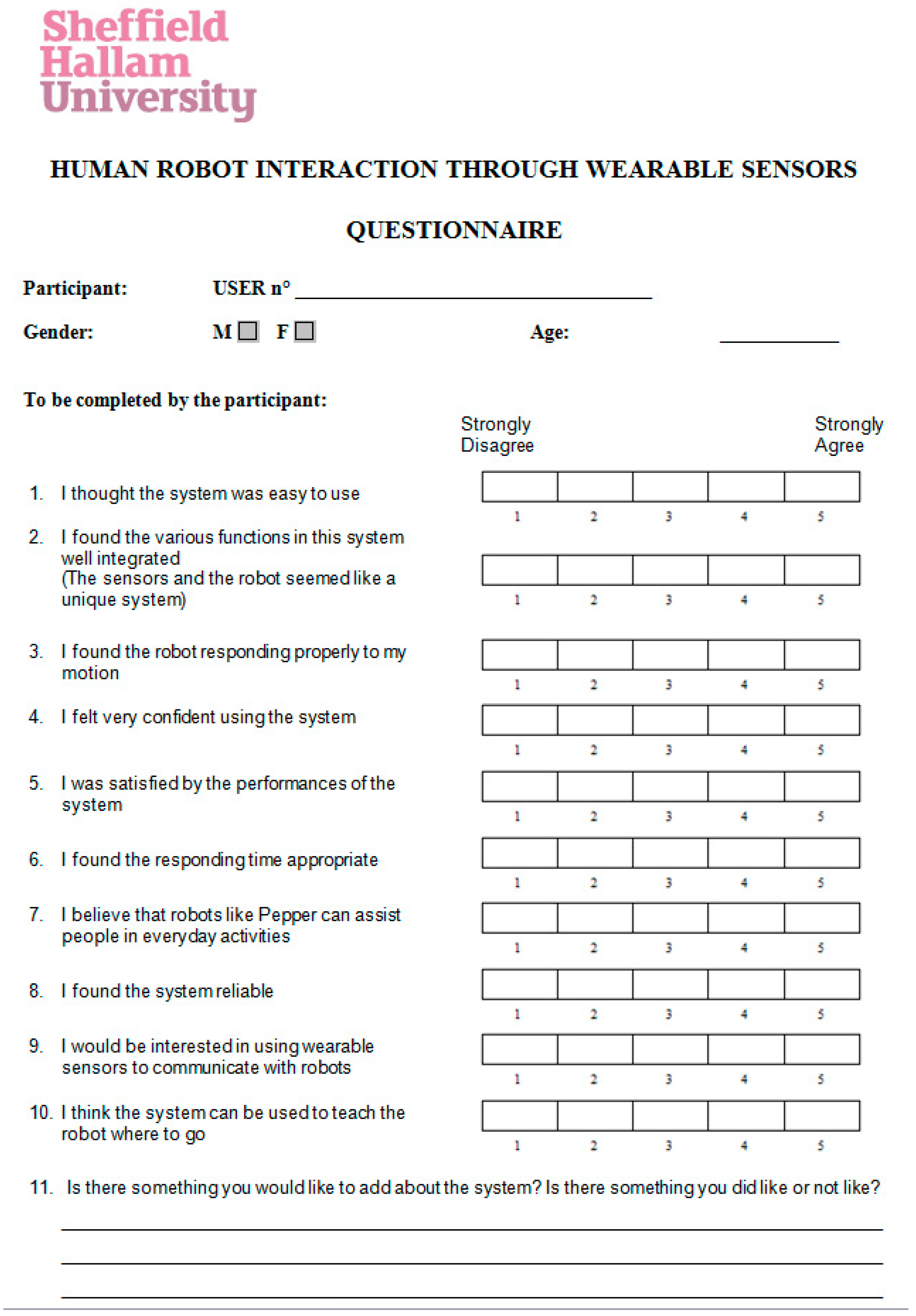
The questionnaire consisted of ten questions with a 5-point scale answer (1: Strongly Disagree, 5: Strongly Agree) and an open question. Questions were a mix of usability and personal evaluation of the system. A copy of the questionnaire is included in Appendix A.
After the experiments, the questionnaires were analyzed evaluating the mean value, the standard deviation, the minimum, maximum, and mode for each answer. Furthermore, the occurrence of the answers and the correlation between the different questions were analyzed. The recorded videos were analyzed to quantify the latency between the user and the robot at the beginning and at the end of the following task. Thus, it was possible to analyze the correlation between the answers given by the participant and the latency. A linear regression analysis was used to determine the relationship between the question “I found the responding time appropriate?” (number 6) and the latency and between some of the other questions.
2.4.3. Robot Control and Data Processing for Human–Robot Walking
The system used in the first experiment was extended by adding a robot control and data processing module, which was implemented on a PC, connected via Bluetooth with the SensFoots, and via WiFi with the Pepper. The module is composed of three main parts:
- Data collection from the SensFoots;
- Real-time extraction of gait parameters;
- Control of robot navigation.
An ad-hoc interface was developed to manage the experimentation and collect and save data from the sensors. All the parts of the data processing module were implemented in Python [38].
The first two parts of this module implement the algorithms described in Section 2.1 and Section 2.2. In the following, we describe the third part which was responsible for translating the gait parameters into commands for moving the robot in accordance with the walking of the participant.
Two controlling strategies were designed adopted to make the robot perform the experimental tasks, i.e., the following task and the follow-me task (see Figure 5).
In the following task, walking speed, turning angle, and stride length were used to control the robot. In practice, the stride length and the turning angle were used to set the final target of each step. After preliminary observations in straight walking tests, an empirical minimum threshold of 0.314 rad was set on the turning angle to avoid that natural imperfections in the movement of the human that would translate in unwanted rotations of the robot. During straight walking slight changes in the turning angle occur (both for inertial sensors and BTS), so the threshold prevents the robot from changing direction at every step.
The robot was given speed commands in such a way that the movement of the robot was as fluent as possible, to avoid sudden starts and stops. The speed of the robot was set to equal the walking speed of the participant or to its maximum if the participant walked faster than the maximum speed of the robot. The time necessary to reach the final position was computed and used to let the robot move at a constant speed for a short while; the speed was updated in the following step. At the end of each step, the position of the robot was checked and compared with the target position to correct the occurring errors in the next step.
To correct the turning angle, the robot was halted for two seconds, as soon as a zero command on the angle was computed, to read the current position, compare it to the target one, and if necessary, make a rotation.
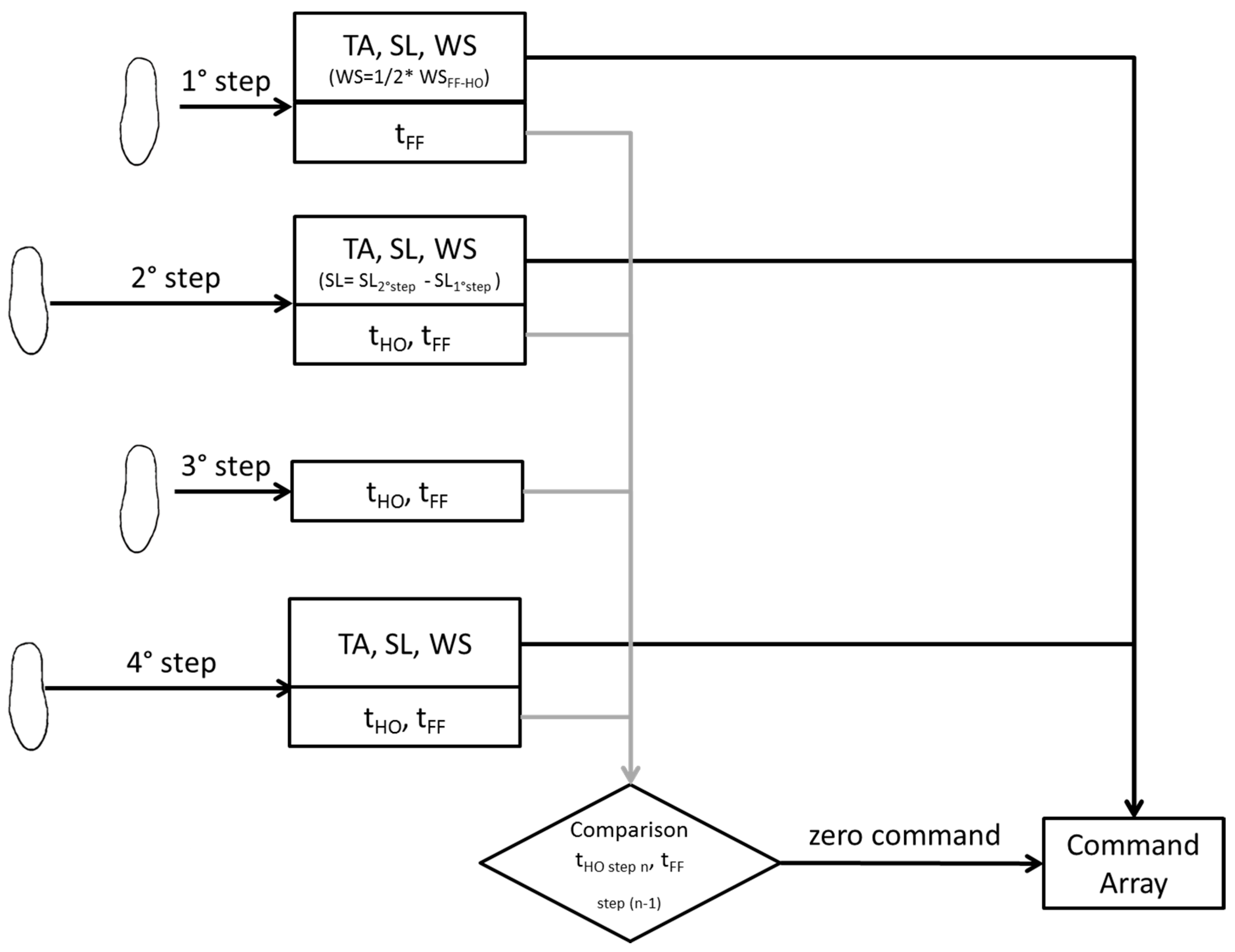
In this task, data from both sensors were used. One foot was used to control the robot, whereas the other one was used to have a faster response of the robot at the beginning of the task and identify the end of the walk. As a matter of fact, to improve the robot’s responsiveness, the first speed command was given as soon as the first step was made by the participant. The stride length and the turning angle were computed as usual. However, the speed was assumed to be equal to the half of the velocity computed between the heel-off and the foot-flat because this represented only half of the full movement. This modification reduced the delay at the beginning of the task and makes the robot moving as soon as the user made the first step. After the first gait, the walking speed was computed as described in the previous paragraph. The rest of the commands were computed on the gait parameter of the second foot and, since the users were asked to start with both feet on a line, the second command given to the robot was evaluated considering the difference between the stride length of the first foot and the one of the second in order not to sum the distance made by both feet. In the software implementation, for each gait, the values of stride length, turning angle, and speed were saved in arrays and analyzed in the control algorithm once per time, and the speed command was sent to the robot.
The sensor on the starting foot was also used to identify the end of the walk, avoiding further delay. The difference between the time of foot-flat of one foot and the heel-off of the other foot was checked at the end of each gait to control whether the user kept on moving or not. When the person stopped, a zero was inserted at the end of the array of commands, which symbolizes that the robot should stop moving. A scheme of how the parameters for each step were used is represented in Figure 6.
In the follow-me task, the stride length and the speed were used in the controlling strategy of the robot. The path for the robot to follow to reach the target was divided into shorter intervals marked by intermediate target positions. After arriving at the first target position, the algorithm computed the difference between the distance traversed by the robot and by the participant. If this difference was below the threshold of 0.5 m the robot proceeded at the walking speed observed in the last gait. Otherwise, it waited for the user to come closer. In this case, the system considers the data coming from only one sensor.
3. Experimental Results
3.1. Experiment I: Validation of the Inertial Sensing Unit
The analysis of the data coming both from the SensFoots and the BTS resulted in 520 gait cycles considering both legs. Concerning the turning angle, we considered the ones evaluated from the segment between the malleolus and the hallux. The results of the comparison between the parameters evaluated with the BTS and the SensFoots are reported in Table 1.
The comparison between the two systems gave good results in term of stride length and walking speed error (0.054 m and 0.067 m/s, respectively) and even the error found on the turning angle was low (0.090 rad). Such errors are certainly acceptable for practical applications as confirmed by the participants’ feedback on the HRI test in the second experiment. Regarding the turning angle, note that we performed the comparison only when the angle was greater than the empirical tolerance threshold of 0.314 for turning the robot (see Section 2.4.3).
3.2. Experiment II: Testing the HRI through SensFoots in Use-Case Scenarios
The second experiment aimed to investigate the feasibility in a realistic use-case scenario of the human–robot interaction system with robot navigation based on data from the participants’ feet.
Our results show that the SensFoot could be used to control the navigation of the Pepper and positive feedback was given by the users about their experience in these two tasks.
Concerning the questionnaire, its reliability was evaluated by evaluating the Cronbach’s alpha, which was equal to 0.642, which can be considered acceptable [39,40]. The answers given by the participants are quite positive (between agree and completely agree) as shown in Table 2, where the mean, standard deviation, mode, minimum, and maximum are reported for each question.
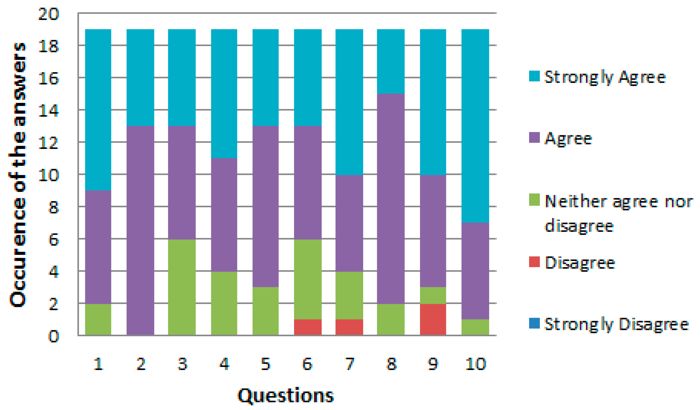
Looking at the occurrence of the answers for each question, for almost all the questions participants chose the agree or strongly agree options, as Figure 7 shows. There are only three questions that have a disagree among the answers, namely question number 6, 7, and 9.
Concerning the question number 6, beyond having disagreed among the answers, it also has the lowest mean value among all the questions. To better understand the reason for this feedback, the correlation between the delays and the answers was analyzed.
From the analysis of the video of the following task, the latency at the beginning and at the end of the test was evaluated. The users took an average of 15.81s ± 3s to perform the task (Maximum = 20.93 and Minimum = 10.94). The average delay at the beginning of the task is 2.88s ± 0.9s, whereas the one at the end is 21.24s ± 5.9s. The long delay at the end of the task was due to several factors, including slower speed of the robot compared to the participant, delays introduced from the wireless communications and the time for computing the algorithm, and the need to adjust the robot navigation because of odometry errors.
All these latency sources where randomly influenced by the actual movements which were, of course, different for each participant, thereby introducing a variability that influenced the opinions. To demonstrate the negative influence of the delay, we extracted the delays from the video recordings of seventeen participants (the ones that agreed to being filmed), then, the Pearson’s correlation coefficient was calculated between the answers to question number 6 and the values of latency at the beginning and at the end of the task.
Regarding the starting latency, the correlation coefficient (r) is equal to −0.13, whereas considering the end latency, the correlation coefficient is equal to −0.57. The significance level of the correlation was evaluated computing the p-value (p) of Student’s t-test. The correlation results statistically significant (p is 0.017) in the end latency, considering a threshold for p equal to 0.05. On the contrary, no significant correlation can be observed between the latency at the beginning of the task and the answers (p = 0.617). Negative values indicate a negative correlation, justified by the fact that lower delays should implicate higher value in the answers. A moderate negative linear correlation can be found between the delay at the end of the task and the answers obtained for question number 6.
A linear regression analysis was applied to create a model between the latency at the end and the answers to question number 6 ("I found the responding time appropriate"). The relation between the latency and the question is:
with R2 (the proportion of the variance in the dependent variable that is predictable from the independent variable) equal to 0.325. The model confirms that better scores can be related to smaller latencies. To give an empirical indication, the average of fully positive (strongly agree) answers to question 6 was calculated in 17.44, therefore, for best results, the system should be able to maintain a latency below 17.44 s. We could further reduce this threshold by considering the lower bound of the confidence interval which is 14.59 s.
Tend ≅ −4.3048 × q6 + 38.9679
The dependent variable was the question number 5 (I was satisfied by the performances of the system), because it was about the general performance of the system, and we used the linear regression to see how this is influenced by the system characteristics covered by the other questions. It was found that question 5 correlates significantly with question 1, “easy to use” (r = 0.57 and p = 0.016), question 3, “properly responding” (r = 0.60 and p = 0.01), question 4, “confidence in the system” (r = 0.51 and p = 0.036), and question 6, “response time” (r = 0.51 and p = 0.036). Then, a linear regression analysis was carried out to explore the links between question number 5 and these other significantly correlated four questions (q1,q3,q4,q6). Table 3 reports the results of the regression analysis, including the standardized coefficients (Beta) and the overall R2. It can be seen that the Beta for question number 6 is 0.273, while for question number 3 and 1 the coefficients reach a higher value, 0.382 and 0.505, respectively. Hence the usability (question 1) accounts for more than half of overall system evaluation (question 5).
4. Discussion and Conclusions
This article aims to present and investigate a system composed of wearable sensors that allows users to move naturally with a robot. First, we implemented an algorithm for human gait analysis by combining those proposed in [26,28]. The accuracy of the SensFoot was analyzed by comparing the results in benchmark movements with those derived by an optical system for motion analysis (BTS). The SensFoot system gave good results in terms of stride length and walking speed as shown in Table 1. Then, we created an integrated HRI system with a Softbank Pepper robot, whose navigation was controlled by the gait parameters extracted from two SensFoot sensors attached to the user’s feet. A prototype of such an HRI system was tested by 19 healthy adults to evaluate its application in two realistic use case scenarios and gather information about the perception of the participants. In these user evaluation experiments, the robot navigation was controlled remotely without any predefined restriction on the relative position of the subjects involved (robot and human). The two tasks tested were: the following task, where the human led the navigation, and the follow-me task, where the robot led the human. As can be observed in Table 2, the system obtained very good feedback from the participants in terms of perceived usability and performances. Most participants agreed that the system was easy to use and well-integrated. They perceived the system as reliable, and they felt quite confident in using it.
In further analysis of participant perceptions and system performance, we observed a correlation between the system’s latencies and participant opinion about response times, which in turn can influence the overall perception of the system. To clarify this relation, we performed a correlation analysis on the latency at the beginning and at the end of the following task, and it was found that the initial delay in starting the movement is considered low and not significant, while the latency at the end of the task is moderately correlated to the participant perception of the system’s responsiveness, showing that best scores are given when the delay in arriving at the final position is lower than a threshold, which was identified in 14.59 s. However, according to the regression analysis, the participants’ overall perception was influenced much more strongly by the ease of use of the system (q1) than by the response time (q6), with beta only half the value of the beta for q1 (see Table 3). Overall the system was evaluated as good.
In summary, the work presented in this paper shows a very good performance and user acceptance of wearable sensors for controlling a mobile robot with human movements. Furthermore, the wearable sensors data allow the robot to adapt its motion to the human’s gait. The positive feedback of the participants in our experiment encourages future investigation on the use of this approach for human–robot walking together.
Despite the good results, some limitations may be found in this study. The results obtained in the comparison between the inertial sensors and the BTS were good enough, but further research should focus on improving the algorithm for the gait analysis and on more refined control strategies for the robot to improve the overall reliability of the system. In particular, even though we found that the error between the measurements of the SL of the BTS and IMUs was low, the accumulation of the error may have a significant impact in longer paths. At the same time, given that the error may never be zero, a more structured HRI behavior of the robot could be implemented to manage this issue, for example, a voice interaction where the user, speaking with the robot, could tell the robot how to compensate and correct its path. In the usability analysis, the relatively low number of participants with the same academic background may have biased the evaluation. To investigate the perceived usability and acceptability deeper, as well as user preferences and likes, and increase the validity of analyses, future experimentations should involve larger groups from different categories of special users, such as the elderly, in comparison with a control group. More sophisticated use-case scenarios and more structured questionnaires could also be used to obtain feedback and better tune the parameters and latency thresholds.
The presented system could also be integrated with different robots. However, given that latency is one of the factors, the speed of the movement should be considered when choosing a robot platform. The planar speed of the Pepper robot is limited to 0.35 m/s, which is slower than the usual human walking speed. Moreover, the robot was not able to move fluently in narrow spaces and in a narrow curve path. Considering the attention that the users gave to the delay in completing the task, the fluency and the maximum speed of the robot should be strongly considered in the design of systems for human–robot walking together.
Finally, this work represents a good starting point to develop adaptive assistive solutions in assistive robotics by integrating wearable sensors with intelligent algorithms. Future works concern the possibility to enhance the system perception of the walking user, improving accuracy in extracted parameters, and the adaptability of the robot, overcoming the current limitations in control and integration.
Author Contributions
Conceptualization, A.M. and F.C.; Methodology A.D.N.; Software, A.M. and D.E.; Hardware, D.E.; Validation, A.M. and A.D.N.; Formal Analysis, A.M. and A.D.N.; Data Curation, A.M.; Writing—Original Draft Preparation, A.M.; Writing—Review and Editing, A.M., A.D.N. and F.C.; Supervision, A.D.N., J.P. and F.C.
Funding
This work was supported by the ACCRA Project, founded by the European Commission–Horizon 2020 Founding Programme (H2020-SCI-PM14-2016) and the National Institute of Information and Communications Technology (NICT) of Japan under grant agreement No. 738251.
Acknowledgments
The authors would like to thank Federica Vannetti and the staff of the MARE Lab (Movement Assistance and Rehabilitation Laboratory) located in the Centro IRCCS “Don Gnocchi” in Florence for the acquisition of the BTS data that were used to evaluate the accuracy of the SensFoot.
Conflicts of Interest
The authors declare no conflict of interest.
Appendix A- User Questionnaire
Figure A1.
Questionnaire submitted to the user at the end of the tests with the Pepper robot.

References
- Di Nuovo, A.; Broz, F.; Cavallo, F.; Dario, P. New Frontiers of Service Robotics for Active and Healthy Ageing. Int. J. Soc. Robot. 2016, 8, 353–354. [Google Scholar] [CrossRef] [Green Version]
- Matarić, M.J.; Scassellati, B. Socially Assistive Robotics. In Springer Handbook of Robotics; Siciliano, B., Khatib, O., Eds.; Springer International Publishing: New York, NY, USA, 2016; pp. 1973–1994. ISBN 978-3-319-32552-1. [Google Scholar] [Green Version]
- Cavallo, F.; Aquilano, M.; Bonaccorsi, M.; Mannari, I.; Carrozza, M.C.; Dario, P. Multidisciplinary approach for developing a new robotic system for domiciliary assistance to elderly people. In Proceedings of the 2011 Annual International Conference of the IEEE Engineering in Medicine and Biology Society, Boston, MA, USA, 30 August–3 September 2011; pp. 5327–5330. [Google Scholar]
- Conti, D.; Cirasa, C.; Di Nuovo, S.; Di Nuovo, A. “Robot, tell me a tale!”: A Social Robot as tool for Teachers in Kindergarten. Interact. Stud. 2019, 20, 1–16. [Google Scholar]
- Donner, M.; Himstedt, M.; Hellbach, S.; Boehme, H.-J. Awakening history: Preparing a museum tour guide robot for augmenting exhibits. In Proceedings of the 2013 European Conference on Mobile Robots (ECMR), Barcelona, Spain, 25–27 September 2013; pp. 337–342. [Google Scholar]
- Kanda, T.; Shiomi, M.; Miyashita, Z.; Ishiguro, H.; Hagita, N. An affective guide robot in a shopping mall. In Proceedings of the 2009 4th ACM/IEEE International Conference on Human–robot Interaction (HRI), La Jolla, CA, USA, 9–13 March 2009; pp. 173–180. [Google Scholar]
- Cavallo, F.; Limosani, R.; Manzi, A.; Bonaccorsi, M.; Esposito, R.; Di Rocco, M.; Pecora, F.; Teti, G.; Saffiotti, A.; Dario, P. Development of a Socially Believable Multi-Robot Solution from Town to Home. Cognit. Comput. 2014, 6, 954–967. [Google Scholar] [CrossRef] [Green Version]
- Manzi, A.; Fiorini, L.; Esposito, R.; Bonaccorsi, M.; Mannari, I.; Dario, P.; Cavallo, F. Design of a cloud robotic system to support senior citizens: the KuBo experience. Auton. Robots 2016, 1–11. [Google Scholar] [CrossRef]
- Hu, J.; Edsinger, A.; Lim, Y.-J.; Donaldson, N.; Solano, M.; Solochek, A.; Marchessault, R. An advanced medical robotic system augmenting healthcare capabilities-robotic nursing assistant. In Proceedings of the 2011 IEEE International Conference on Robotics and Automation (ICRA), Shanghai, China, 9–13 May 2011; pp. 6264–6269. [Google Scholar]
- Penders, J.; Alboul, L.; Witkowski, U.; Naghsh, A.; Saez-Pons, J.; Herbrechtsmeier, S.; El-Habbal, M. A robot swarm assisting a human fire-fighter. Adv. Robot. 2011, 25, 93–117. [Google Scholar] [CrossRef]
- Penders, J.; Ghosh, A. Human robot interaction in the absence of visual and aural feedback: Exploring the haptic sense. Procedia Comput. Sci. 2015, 71, 185–195. [Google Scholar] [CrossRef]
- Turchetti, G.; Micera, S.; Cavallo, F.; Odetti, L.; Dario, P. Technology and innovative services. IEEE Pulse 2011, 2, 27–35. [Google Scholar] [CrossRef]
- Cai, H.; Lin, Y. Coordinating Cognitive Assistance with CognitiveEngagement Control Approaches inHuman–Machine Collaboration. IEEE Trans. Syst. Man Cybern. Part A Syst. Hum. 2012, 42, 286–294. [Google Scholar] [CrossRef]
- Di Nuovo, A.; Broz, F.; Wang, N.; Belpaeme, T.; Cangelosi, A.; Jones, R.; Esposito, R.; Cavallo, F.; Dario, P. The multi-modal interface of Robot-Era multi-robot services tailored for the elderly. Intell. Serv. Robot. 2018, 11, 109–126. [Google Scholar] [CrossRef]
- Cavallo, F.; Esposito, R.; Limosani, R.; Manzi, A.; Bevilacqua, R.; Felici, E.; Di Nuovo, A.; Cangelosi, A.; Lattanzio, F.; Dario, P. Robotic Services Acceptance in Smart Environments With Older Adults: User Satisfaction and Acceptability Study. J. Med. Internet Res. 2018, 20, 264. [Google Scholar] [CrossRef]
- Yan, H.; Ang, M.H., Jr.; Poo, A.N. A survey on perception methods for human--robot interaction in social robots. Int. J. Soc. Robot. 2014, 6, 85–119. [Google Scholar] [CrossRef]
- Xiao, Y.; Zhang, Z.; Beck, A.; Yuan, J.; Thalmann, D. Human--robot interaction by understanding upper body gestures. Presence Teleop. Virt. Environ. 2014, 23, 133–154. [Google Scholar] [CrossRef]
- Cubo, J.; Nieto, A.; Pimentel, E. A cloud-based Internet of Things platform for ambient assisted living. Sensors 2014, 14, 14070–14105. [Google Scholar] [CrossRef] [PubMed]
- Ray, P.P. Internet of Robotic Things: Concept, Technologies, and Challenges. IEEE Access 2016, 4, 9489–9500. [Google Scholar] [CrossRef]
- Ghosh, A.; Penders, J.; Jones, P.E.; Reed, H. Experience of using a haptic interface to follow a robot without visual feedback. In Proceedings of the 23rd IEEE International Symposium on Robot and Human Interactive Communication (2014 RO-MAN), Edinburgh, Scotland, 25–29 August 2014; pp. 329–334. [Google Scholar]
- Cifuentes, C.A.; Frizera, A.; Carelli, R.; Bastos, T. Human--robot interaction based on wearable IMU sensor and laser range finder. Rob. Auton. Syst. 2014, 62, 1425–1439. [Google Scholar] [CrossRef]
- Papageorgiou, X.S.; Chalvatzaki, G.; Tzafestas, C.S.; Maragos, P. Hidden markov modeling of human normal gait using laser range finder for a mobility assistance robot. In Proceedings of the 2014 IEEE International Conference on Robotics and Automation (ICRA), Hong Kong, China, 31 May–7 June 2014; pp. 482–487. [Google Scholar]
- Alvarez-Santos, V.; Pardo, X.M.; Iglesias, R.; Canedo-Rodriguez, A.; Regueiro, C.V. Feature analysis for human recognition and discrimination: Application to a person-following behaviour in a mobile robot. Rob Auton Syst. 2012, 60, 1021–1036. [Google Scholar] [CrossRef]
- Wu, L.; An, Z.; Xu, Y.; Cui, L. Human tracking based on LRF and wearable IMU data fusion. In Proceedings of the 12th International Conference on Information Processing in Sensor Networks, Philadelphia, PA, USA, 8–11 April 2013; pp. 349–350. [Google Scholar]
- Vaughan, C.L.; Davis, B.L.; O’connor, J.C. Dynamics of Human Gait; Human Kinetics Publishers: Champaign, IL, USA, 1992; Volume 2. [Google Scholar]
- Sabatini, A.M.; Martelloni, C.; Scapellato, S.; Cavallo, F. Assessment of walking features from foot inertial sensing. IEEE Trans. Biomed. Eng. 2005, 52, 486–494. [Google Scholar] [CrossRef] [Green Version]
- Yang, S.; Li, Q. Inertial sensor-based methods in walking speed estimation: A systematic review. Sensors 2012, 12, 6102–6116. [Google Scholar] [CrossRef] [PubMed]
- Mariani, B.; Hoskovec, C.; Rochat, S.; Büla, C.; Penders, J.; Aminian, K. 3D gait assessment in young and elderly subjects using foot-worn inertial sensors. J. Biomech. 2010, 43, 2999–3006. [Google Scholar] [CrossRef] [PubMed]
- Alvarez, J.C.; González, R.C.; Alvarez, D.; López, A.M.; Rodriguez-Uria, J. Multisensor approach to walking distance estimation with foot inertial sensing. In Proceedings of the 29th Annual International Conference of the IEEE Engineering in Medicine and Biology Society, (EMBS 2007), Lyon, France, 23–26 August 2007; pp. 5719–5722. [Google Scholar]
- Rampp, A.; Barth, J.; Schülein, S.; Gaßmann, K.-G.; Klucken, J.; Eskofier, B.M. Inertial sensor-based stride parameter calculation from gait sequences in geriatric patients. IEEE Trans. Biomed. Eng. 2015, 62, 1089–1097. [Google Scholar] [CrossRef]
- Dadashi, F.; Mariani, B.; Rochat, S.; Büla, C.J.; Santos-Eggimann, B.; Aminian, K. Gait and foot clearance parameters obtained using shoe-worn inertial sensors in a large-population sample of older adults. Sensors 2013, 14, 443–457. [Google Scholar] [CrossRef] [PubMed]
- Sagawa, K.; Inooka, H.; Satoh, Y. Non-restricted measurement of walking distance. In Proceedings of the 2000 IEEE International Conference on Systems, Man, and Cybernetics, Nashville, TN, USA, 8–11 October 2000; Volume 3, pp. 1847–1852. [Google Scholar]
- Rovini, E.; Maremmani, C.; Moschetti, A.; Esposito, D.; Cavallo, F. Comparative Motor Pre-clinical Assessment in Parkinson’s Disease Using Supervised Machine Learning Approaches. Ann. Biomed. Eng. 2018, 1–12. [Google Scholar] [CrossRef] [PubMed]
- Favre, J.; Jolles, B.M.; Siegrist, O.; Aminian, K. Quaternion-based fusion of gyroscopes and accelerometers to improve 3D angle measurement. Electron. Lett. 2006, 42, 612–614. [Google Scholar] [CrossRef]
- Pandey, A.K.; Gelin, R. A Mass-Produced Sociable Humanoid Robot: Pepper: The First Machine of Its Kind. IEEE Robot. Autom. Mag. 2018, 25, 40–48. [Google Scholar] [CrossRef]
- Pepper Description. Available online: https://www.softbankrobotics.com/emea/en/robots/pepper/find-out-more-about-pepper (accessed on 26 July 2018).
- Pepper Locomotion. Available online: http://doc.aldebaran.com/2-1/naoqi/motion/control-walk.html (accessed on 26 July 2018).
- Van Rossum, G.; Drake, F.L., Jr. Python Reference Manual; Centrum voor Wiskunde en Informatica: Amsterdam, The Netherlands, 1995. [Google Scholar]
- Conti, D.; Di Nuovo, S.; Buono, S.; Di Nuovo, A. Robots in education and care of children with developmental disabilities: a study on acceptance by experienced and future professionals. Int. J. Soc. Robot. 2017, 9, 51–62. [Google Scholar] [CrossRef]
- Kline, P. Handbook of Psychological Testing; Routledge: London, UK, 2013. [Google Scholar]
Figure 1.
The SensFoot device.

Figure 2.
Gait parameters: SL: Stride Length and TA: Turning Angle [28].
Figure 2.
Gait parameters: SL: Stride Length and TA: Turning Angle [28].

Figure 3.
Scheme of the following task (a) and follow-me task (b).


Figure 4.
Example of tests with users (a), and a sequence from the following task (b) and from the follow-me task (c).
Figure 4.
Example of tests with users (a), and a sequence from the following task (b) and from the follow-me task (c).

Figure 5.
A diagram of the robot control scheme.

Figure 6.
Parameters evaluation at each step in the following task (FF = Foot Flat, HO = Heel-Off).

Figure 7.
The occurrence of the answers for each question.


Table 1.
The mean absolute error, standard deviation, and correlation between SensFoot and BTS.
| Mean Absolute Error | Mean Absolute Error Standard Deviation | R | |
|---|---|---|---|
| Stride Length (m) | 0.054 | ±0.045 | 0.931 |
| Walking Speed (m/s) | 0.067 | ±0.058 | 0.925 |
| Turning Angle >0.314 (rad) | 0.090 | ±0.065 | 0.997 |
Table 2.
Results of the questionnaires made after the experimentation. Values are in a 5-point Likert scale from 1 (completely disagree) to 5 (completely agree).
Table 2.
Results of the questionnaires made after the experimentation. Values are in a 5-point Likert scale from 1 (completely disagree) to 5 (completely agree).
| Item | Mean | Standard Deviation | Min | Max | Mode |
|---|---|---|---|---|---|
| 1. I thought the system was easy to use. | 4.42 | ±0.69 | 3 | 5 | 5 |
| 2. I found the various functions in this system well integrated. | 4.32 | ±0.48 | 4 | 5 | 4 |
| 3. I found the robot responding properly to my motion. | 4.00 | ±0.82 | 3 | 5 | 4 |
| 4. I felt very confident using the system. | 4.21 | ±0.79 | 3 | 5 | 5 |
| 5. I was satisfied with the performances of the system. | 4.16 | ±0.69 | 3 | 5 | 4 |
| 6. I found the responding time appropriate. | 3.95 | ±0.91 | 2 | 5 | 4 |
| 7. I believe that robots like Pepper can assist people in everyday activities. | 4.21 | ±0.92 | 2 | 5 | 5 |
| 8. I found the system reliable. | 4.11 | ±0.57 | 3 | 5 | 4 |
| 9. I would be interested in using wearable sensors to communicate with robots | 4.21 | ±0.98 | 2 | 5 | 5 |
| 10. I think the system can be used to teach the robot where to go. | 4.40 | ±0.61 | 3 | 5 | 5 |
Table 3.
Linear regression analysis.
| Independent Variable | Dependent Variable | R2 | Beta |
|---|---|---|---|
| q1 | q5 | 0.746 | 0.505 |
| q3 | 0.382 | ||
| q4 | 0.167 | ||
| q6 | 0.273 |
© 2019 by the authors. Licensee MDPI, Basel, Switzerland. This article is an open access article distributed under the terms and conditions of the Creative Commons Attribution (CC BY) license (http://creativecommons.org/licenses/by/4.0/).
Share and Cite
MDPI and ACS Style
Moschetti, A.; Cavallo, F.; Esposito, D.; Penders, J.; Di Nuovo, A. Wearable Sensors for Human–Robot Walking Together. Robotics 2019, 8, 38. https://doi.org/10.3390/robotics8020038
AMA Style
Moschetti A, Cavallo F, Esposito D, Penders J, Di Nuovo A. Wearable Sensors for Human–Robot Walking Together. Robotics. 2019; 8(2):38. https://doi.org/10.3390/robotics8020038
Chicago/Turabian StyleMoschetti, Alessandra, Filippo Cavallo, Dario Esposito, Jacques Penders, and Alessandro Di Nuovo. 2019. "Wearable Sensors for Human–Robot Walking Together" Robotics 8, no. 2: 38. https://doi.org/10.3390/robotics8020038
Note that from the first issue of 2016, this journal uses article numbers instead of page numbers. See further details here.