V2SOM: A Novel Safety Mechanism Dedicated to a Cobot’s Rotary Joints †


Department of GMSC, Pprime Institute CNRS, ENSMA, University of Poitiers, UPR 3346, 86073 Poitiers, France
*
Author to whom correspondence should be addressed.
†
This paper is an extended version of our paper published in Ayoubi, Y.; Laribi, M.A.; Zeghloul, S.; Arsicault, M. Design of V2SOM: The Safety Mechanism for Cobot’s Rotary Joints. In Proceedings of the IFToMM Symposium on Mechanism Design for Robotics, Udine, Italy, 11–13 August 2018.
Robotics 2019, 8(1), 18; https://doi.org/10.3390/robotics8010018
Submission received: 11 January 2019
/
Revised: 25 February 2019
/
Accepted: 25 February 2019
/
Published: 6 March 2019
(This article belongs to the Special Issue Mechanism Design for Robotics)
Abstract
:Unlike “classical” industrial robots, collaborative robots, known as cobots, implement a compliant behavior. Cobots ensure a safe force control in a physical interaction scenario within unknown environments. In this paper, we propose to make serial robots intrinsically compliant to guarantee safe physical human–robot interaction (pHRI), via our novel designed device called V2SOM, which stands for Variable Stiffness Safety-Oriented Mechanism. As its name indicates, V2SOM aims at making physical human–robot interaction safe, thanks to its two basic functioning modes—high stiffness mode and low stiffness mode. The first mode is employed for normal operational routines. In contrast, the low stiffness mode is suitable for the safe absorption of any potential blunt shock with a human. The transition between the two modes is continuous to maintain a good control of the V2SOM-based cobot in the case of a fast collision. V2SOM presents a high inertia decoupling capacity which is a necessary condition for safe pHRI without compromising the robot’s dynamic performances. Two safety criteria of pHRI were considered for performance evaluations, namely, the impact force (ImpF) criterion and the head injury criterion (HIC) for, respectively, the external and internal damage evaluation during blunt shocks.
1. Introduction
Robotics was introduced into industry at the beginning of the 1960s. Several industries (e.g., automobile, military and manufacture) improved their productivity rates thanks to the use of robots, taking advantage of their capabilities to execute repetitive tasks much faster than humans. Those classical industrial robots generally executed the production tasks in highly secured cells, out of the reach of human operators. Nevertheless, other tasks cannot be easily automated, and human execution is therefore required, such as complex tasks or the manipulation of heavy loads. The use of collaborative robots, known as cobots, emerges as a solution to improve the execution of those tasks where a human is required. Unlike classical industrial robots, usually isolated to avoid physical contact with humans, cobots actually coexist with them in a shared common workspace and cooperate with them to accomplish the desired tasks. While a robot can magnify human capabilities, such as their force, speed, or precision, humans can bring a global knowledge and their experience to jointly execute the tasks [1]. With the fourth industrial revolution, the number of cobots has increased [2] and they are being used more and more to assist well-experienced humans.
Safety is the most important issue to solve before establishing collaborative tasks between humans and robots, where a high risk of collisions between them is evident and may result in damage to humans. In this context, research efforts are focused on the design of solutions to reduce the energy transferred by the robot in the case of collision, decreasing the risk of injury for the human [3]. In this regard, some basic solutions have been proposed. For instance, Park et al. introduce the use of a viscoelastic covering on the robot’s body to reduce the impact forces [4]. Fritzsche et al. propose monitoring the contact forces by providing the robot’s body with a tactile sensor used as an artificial skin [5]. Furthermore, several control approaches have been proposed to provide the robot with a compliant behavior while it executes a task. These compliant control strategies typically make it possible to assign a dynamic relationship between the robot and the environment, enabling the interaction behavior to be controlled by properly selecting the dynamic parameters. The compliant behavior can be either implemented in the robot end-effector or in the joints, for the Cartesian or joint space cases, respectively. A complete survey of the different collaborative control schemes can be found in [6]. On the other hand, mechanical solutions have also been proposed to provide an intrinsic compliance to the robot. Among these compliant mechanisms, variable stiffness actuators (VSAs) allow the introduction of an intrinsic compliance to the robot joints [7]. These mechanisms are capable of providing adjustable stiffness to the joints, which can be adjusted according to the needs.
Overall, two main approaches are well-respected for the human safety versus robot dynamics trade-off. These approaches are summarized under active impedance control and passive compliance (PC). The first approach suffers from a low latency in the case of blunt HR collision that reaches up to 200 ms [8,9], which may endanger human safety. In contrast, passive compliance presents a robust instantaneous response to uncontrolled HR shocks. In general, what makes robots intrinsically dangerous is the combination of high velocities and massive mobile inertia [10]. This latter aspect is a key feature in making cobots behave safely without limiting the desired dynamic performances, that is, by decoupling the cobot’s colliding part inertia from the heavy rotor side inertia via passively compliant joints. In this respect, the earliest works yielded the series elastic actuator and the series parallel elastic actuator [11,12], where the stiffness is constant. As this behavior cannot cope with a cobot’s load variation and its dynamics, Zinn proposed the concept DM² in [13] that improves the control via the double actuation system. Subsequently, the concept of variable stiffness actuator (VSA) gained more attention [8,14,15,16,17] from the robotics community. The VSA acts upon a wide range of a cobot’s load by adapting its apparent stiffness. Note that every VSA is different, for example, in terms of its stiffness profile or working principal. A well-detailed study of a VSA’s design goal is presented in [8]. There are some examples of systems implementing VAS control with a sensor-based approach, which usually leads to a more complex mechanical structure, and a sensorless approach, as commonly used in the position/stiffness control [18,19]. This study’s proposed approach, leading to the prototype V2SOM [20], presents the following novelties with respect to the literature:
- The stiffness behavior, in the vicinity of zero deflection, is smoothened via a cam-follower mechanism.
- The stiffness sharply sinks to maintain, theoretically as shown in Figure 5, a constant torque threshold in the case of collision.
- The torque threshold, , is tunable according to load variation.
The focus of this paper is V2SOM’s design which is dedicated to a cobot’s rotary joints. In Section 2, the mechanism’s working principle is presented by emphasizing its design concept and the two functional blocks: stiffness generation block and stiffness adjusting block. The design methodology applied to obtain the first V2SOM prototype is presented in Section 3. The theoretical as well as experimental characteristics of the first V2SOM prototype are addressed at the end of that section. Section 4 presents a comparative study between V2SOM and a constant stiffness (CS) profile, comparing the choice of both HIC and ImpF criteria via simulation. Section 5 summarizes some notable outcomes and perspectives of the present study.
2. V2SOM’s Working Principle
The design concept of the variable stiffness mechanism (VSM) aims to make load-adjustable compliant robots by implementing VSM in series with the actuation system, as depicted in Figure 1. However, a VSM can simply be described as a tunable spring with a basic nonlinear stiffness profile.
2.1. Architecture Description
V2SOM contains two functional blocks, as depicted in Figure 2, namely, a nonlinear stiffness generator block (SGB) and a stiffness adjusting block (SAB). To simplify the understanding of V2SOM, we presented a kinematic scheme in Figure 2b with a semi-view that is symmetrical to the rotation axis L1. The SGB is based on a cam-follower mechanism where the cam’s rotation about L5 axis, between −90° and 90°, induces the translation of its follower according to the slider L6. Then, the follower extends its attached spring. At this level, a deflection angle corresponds to a torque value exerted on the cam. The wide range of this elastic deflection must be reduced to a lower range of , as it is widely considered in most VSAs [21,22]. To this end, the SAB acts as a reducer by using a gear ring system. Furthermore, the SAB serves as a variable reducer due to the linear actuator M that controls the distance while driving the gearing in a lever-like configuration. The reduction ratio of the SAB is continuously tunable allowing V2SOM to cope with the external load , where the link side makes a deflection angle relative to the actuator side.
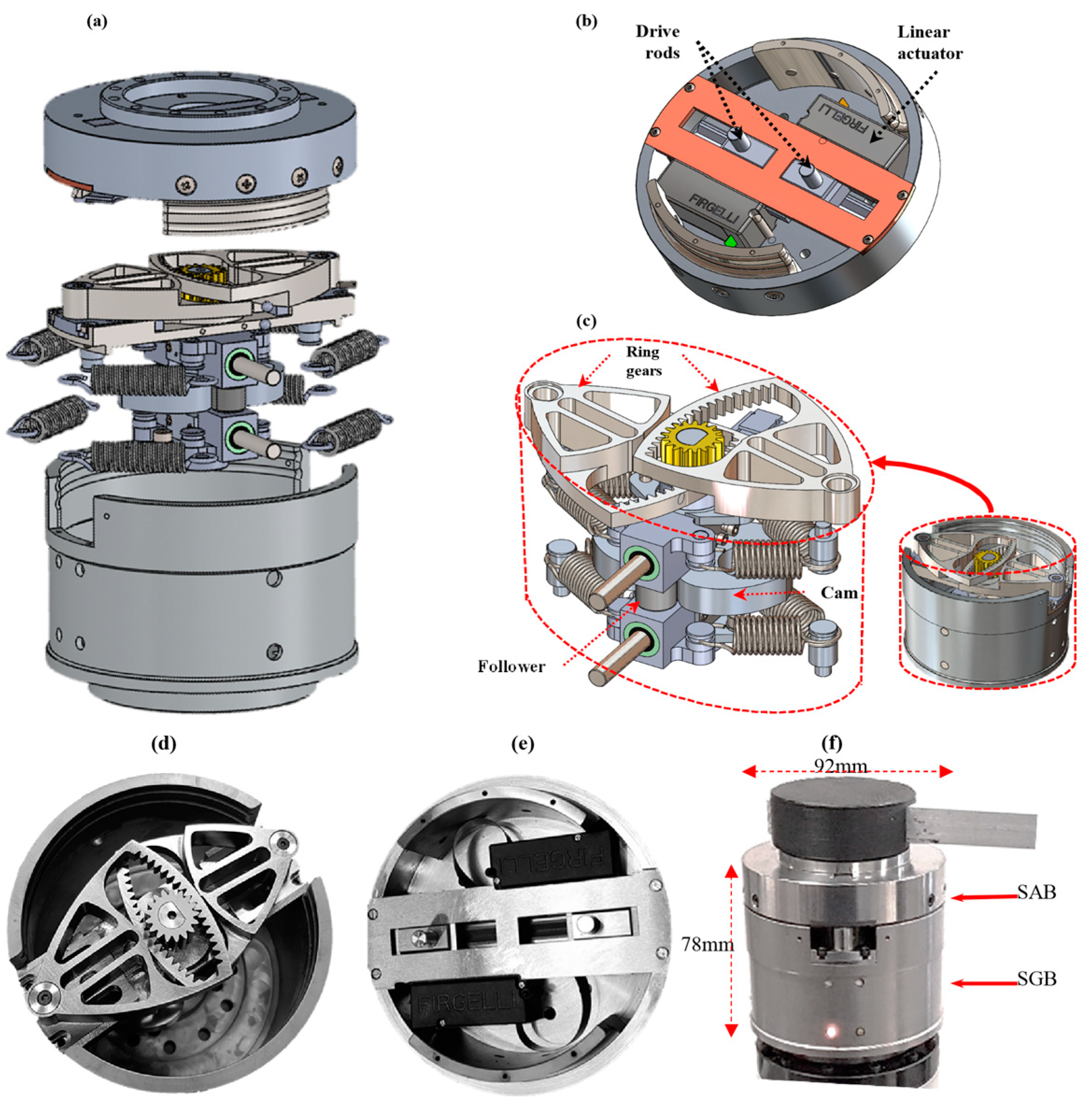
The V2SOM CAD model as well as its first prototype are presented in Figure 3. More details are given in the V2SOM patent [20] and [15,16]. The V2SOM blocks as shown in Figure 3, with CAD models and corresponding prototypes, are connected rigidly to fulfil each step of a dedicated task:
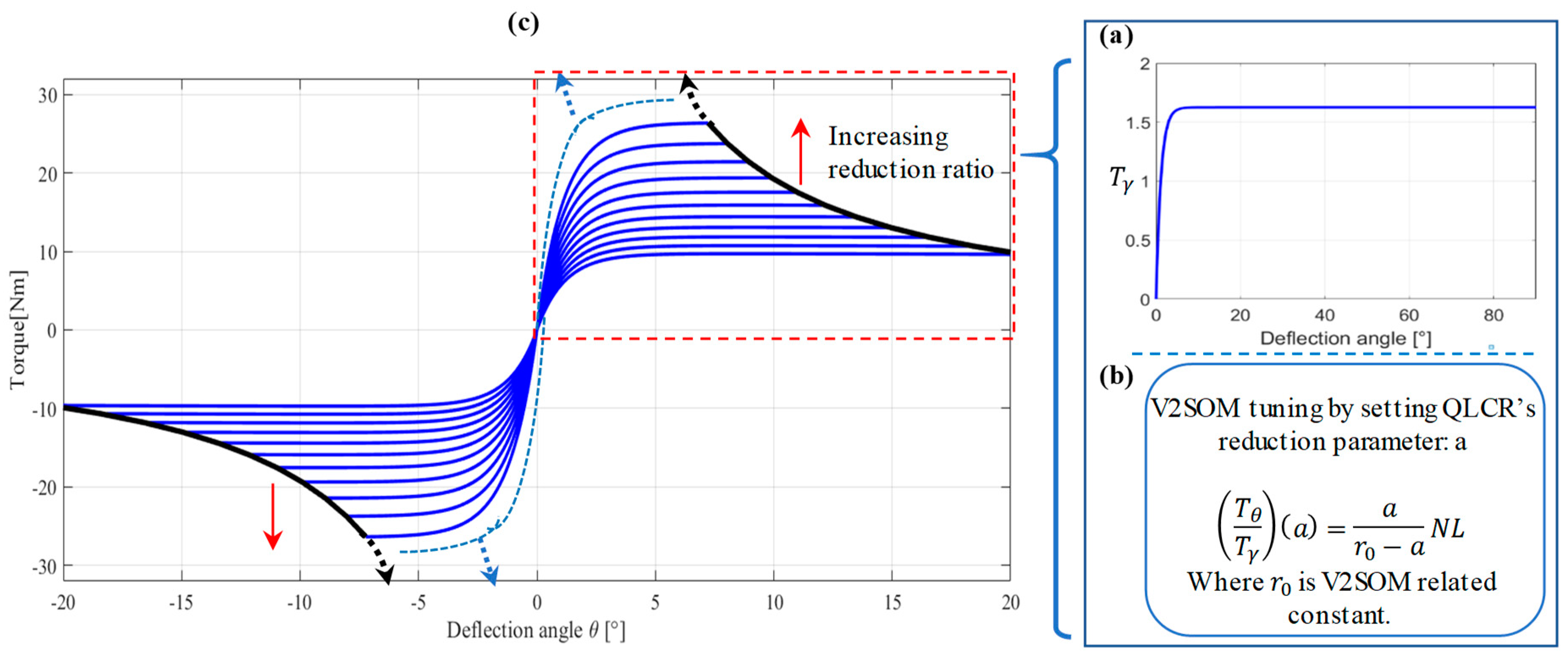
- The SGB is characterized by the curve of the torque vs. the deflection angle . This curve is obtained through the cam profile, the followers. and other design parameters. The basic torque curve leading to the torque characteristic of the V2SOM is depicted in Figure 4a. This basic curve is elaborated with a torque threshold equal to , for the present prototype.
- The SAB is considered as a quasi-linear continuous reducer (QLCR) and defined by its ratio expression given in Figure 4b. The ratio is a function of the nonlinear (NL) factor, deflection angle , and reducer’s tuning parameter . The NL factor is linked to the SAB’s internal parameters and can be approximated with a constant when the deflection range is between and ; this issue will be discussed in the next section.
Figure 4c shows an illustration of the V2SOM characteristic resulting from Figure 4a with seven increasing reduction ratio settings (seven values of torque tuning). Because of the QLCR behavior of the SAB, the curves in Figure 4c follow the profile of the basic torque curve given in Figure 4b which will be detailed in Section 2.2.
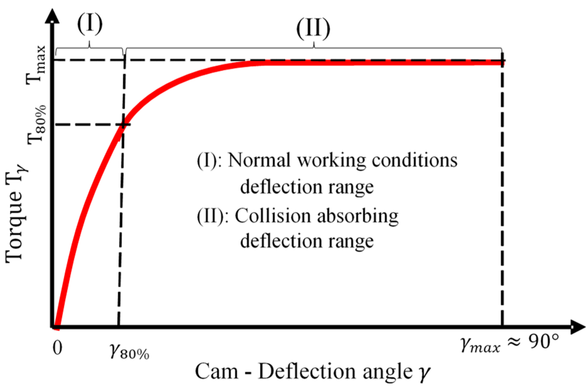
In general, V2SOM has two working modes between which a transition smoothly takes place in the case of blunt shock as illustrated in Figure 5. The high stiffness mode (I) is defined within the deflection range and the torque range . The value defines the normal working conditions of the torque. Exceeding this torque value means that the shock absorbing mode (II) is triggered, characterized with low stiffness thus leading to the torque threshold .
2.2. Stiffness Generator Block (SGB)
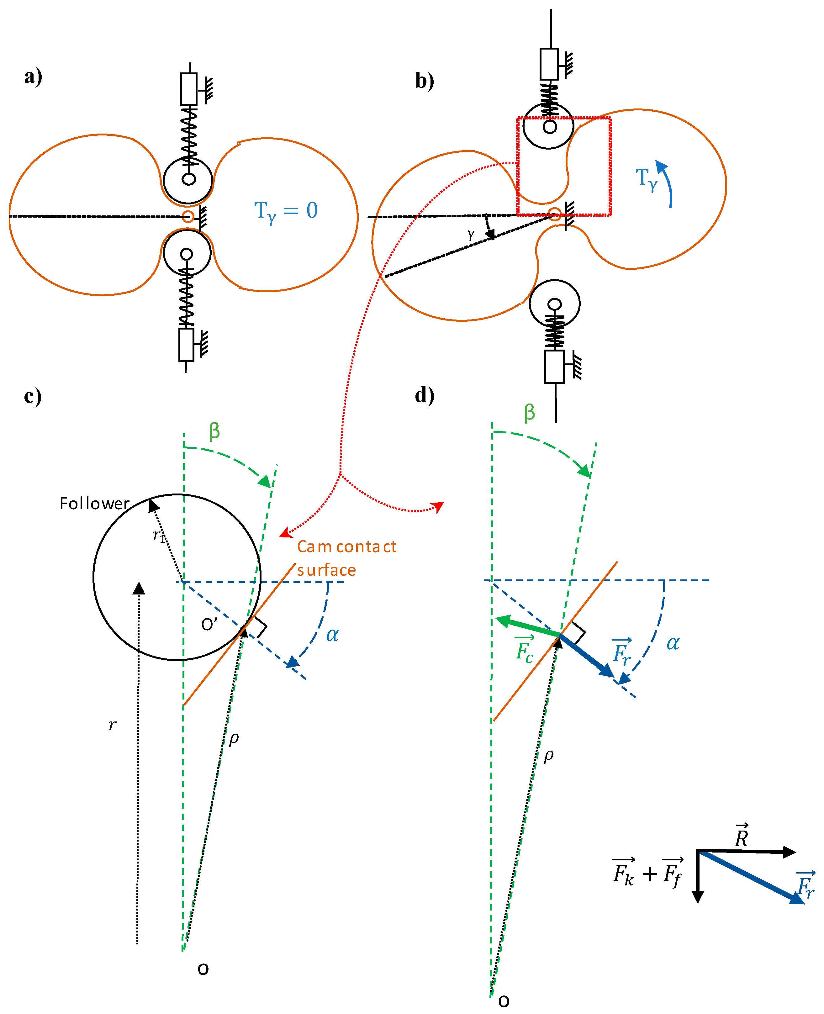
In order to explain the working principle of the stiffness generator block, its corresponding simplified sketches are shown in Figure 6. A relaxed spring configuration with the cam-follower is presented in Figure 6a. In this particular configuration, the supported torque around the rotation axis is equal to zero, . The increase of the torque leads to an elastic deflection angle as well as a linear motion of the sliders. The rotation of the cam, as depicted in Figure 6b, compresses the springs, allowing the followers to keep contact with the cam profile. Contact surface analysis allowed us to identify the interaction forces and then establish the static equilibrium conditions. A graphic representation of a contact surface between cam and follower is shown in Figure 6c,d. Below, geometric parameters are listed in addition to the corresponding static equilibrium force equations.
- : Distance among the rotation center, point , and contact point of the cam-follower.
- : Follower’s radius.
- : Distance of the follower’s center, point , to the cam’s rotation center. The rest value is .
- : Resultant force at the cam-follower contact.
- : Component of in charge of deflection torque . The relations can be written as follows:
Notice that the components of of each follower, according to the axis containing the rotation center, are cancelling each other.
- : Friction force at the slider supporting the follower.
- : Compression force of the spring.
- : Force applied on the slider perpendicular to its axis.
The following equations can be deduced from the static equilibrium condition, giving the relation between forces , , and :
Considering a Coulomb-type friction at the slider joint and a proportional expression to and , the force and friction coefficient are expressed, respectively, as follows:
The following relations between the geometric parameters, useful for the equation rearrangement, can be obtained from Figure 6c:
Equation (4) is rearranged as follows:
A rotation of the cam from equilibrium position, yields to follower motion defined by a translation of the slider from initial position, . The principle of virtual work applied to the SGB can be written as follows:
Then, Equation (6) is simplified as follows:
By substituting in Equation (7), we obtain:
where , and .
As Equation (8) is valid for any , one may write the following:
Combining Equations (1)–(3), (5), and (9) results in the following:
The first step to find the cam’s profile, that is, the set of points defined as the pair (), is to solve the second differential Equation of (10). Then, the pairs () are found using Equation (5).
In this regard, the following numerical scheme is adopted:
Substituting (11) in the second Equation of (10), leads to:
where , and .
For the sake of simplicity, we presented a combination of four extension springs (see Figure 3b) as a single compression spring in Figure 6. Thus, the springs in Figure 6 have the following characteristic:
where K and are the extension springs’ stiffness and initial length, respectively, and is a constant, depicted in Figure 7, related to clash constraints.
It is now clear that the cam’s profile depends on the characteristic of deflection torque vs. deflection angle . The SGB of V2SOM has the torque characteristic shown in Figure 8, where the two functional modes are shown. The equation of the curve in Figure 8 is given by the following:
where and are two constants of the designer’s choice.
The first mode, which we call normal operational condition mode (i.e., no collision takes place), is defined within the deflection range (I) of Figure 8. The range (I) is characterized by a torque value and a user chosen value, that represents 80% of . Accordingly, the range (II) represents the collision mode where the deflection torque at the SGB exceeds the threshold of .
2.3. Stiffness Adjusting Block (SAB)
The interval delimitating the deflection angle of the SGB is within which is larger then numerous cobot applications (e.g., for humanoid arm application [11]). The tuning of the V2SOM’s stiffness in a continuous manner is supported by the stiffness adjusting block (SAB). This block’s functionality is defined by its capability to adjust the deflection angle, the output of the SGB. The SAB can be considered as a torque amplifier.
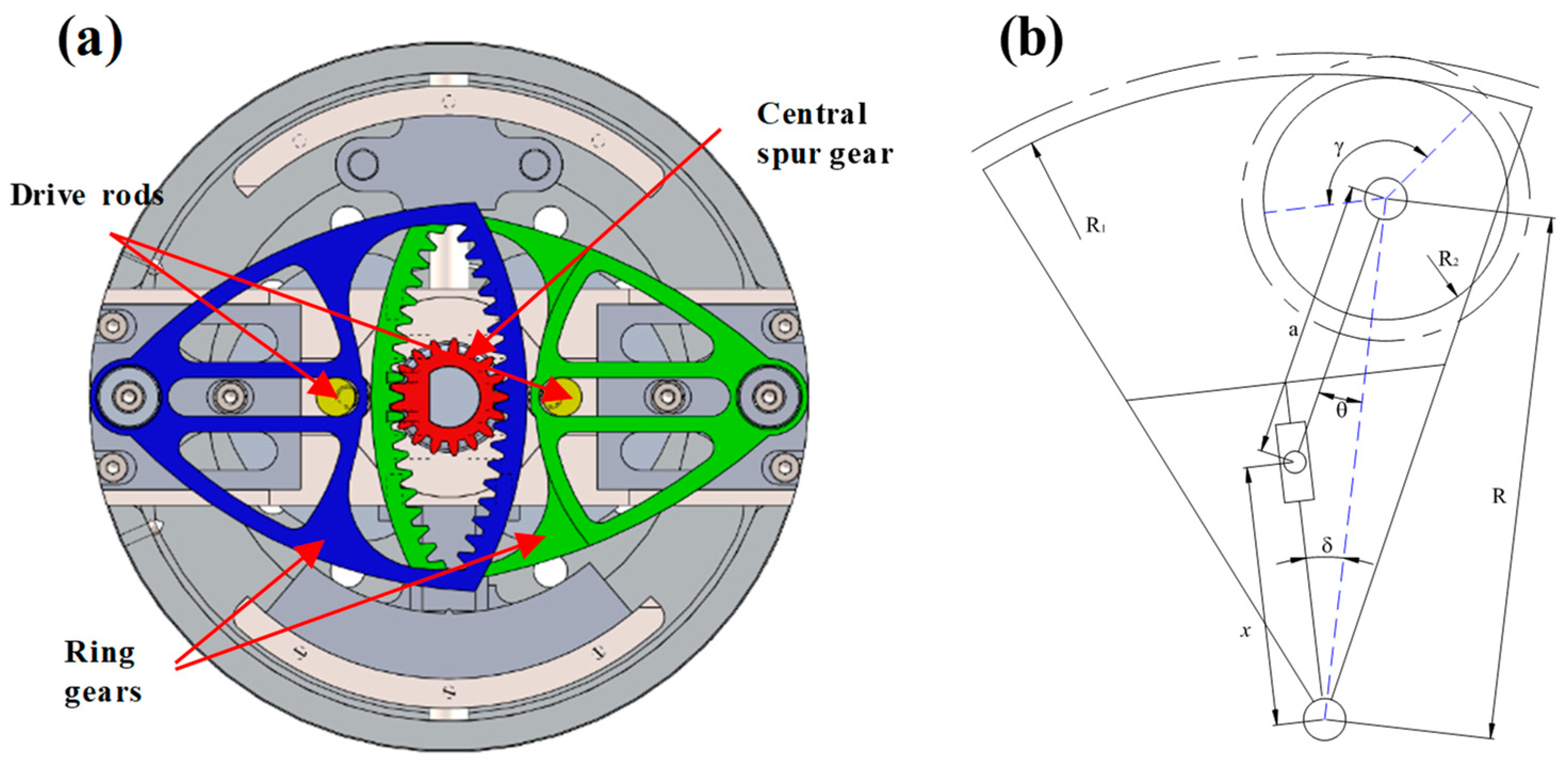
As a gearbox, the main function of the SAB is to vary the torque. This block is composed of a set of gears, two ring gears and one spur gear (see Figure 9a). The ring gears are considered as the input carried by a double lever arm system applying a torque. The lever arm system is composed of two drive rods and a prismatic joint L2, as shown in Figure 9a and Figure 2, respectively. The displacement of each driven rod is defined by the parameter . The actuator M, as depicted in Figure 2b, allows one to change the value of the parameter acting on the reduction ratio of the SAB. The parameter defines the distance between the driven rod and the cam center. The position of the driven rod can also be defined by the parameter when it slides along the ring gear. All these parameters are given in Figure 9b.
V2SOM’s deflection angle at the output is , Figure 9b, which is the output of the SAB. The relation between the output torque and the input torque is given by the following:
Equation (15-a) reports the condition of the tuning parameter appearing in the rate of the input–output torque equation and defines the torque behavior of the SAB. When the input angle changes inside the bounding interval , the output angle is still limited inside the range given by Equation (15-b).
An approximation of Equation (15) can be written when the deflection is close to zero value using second-order Taylor polynomial approximation. The obtained equation, noted , is expressed as follows:
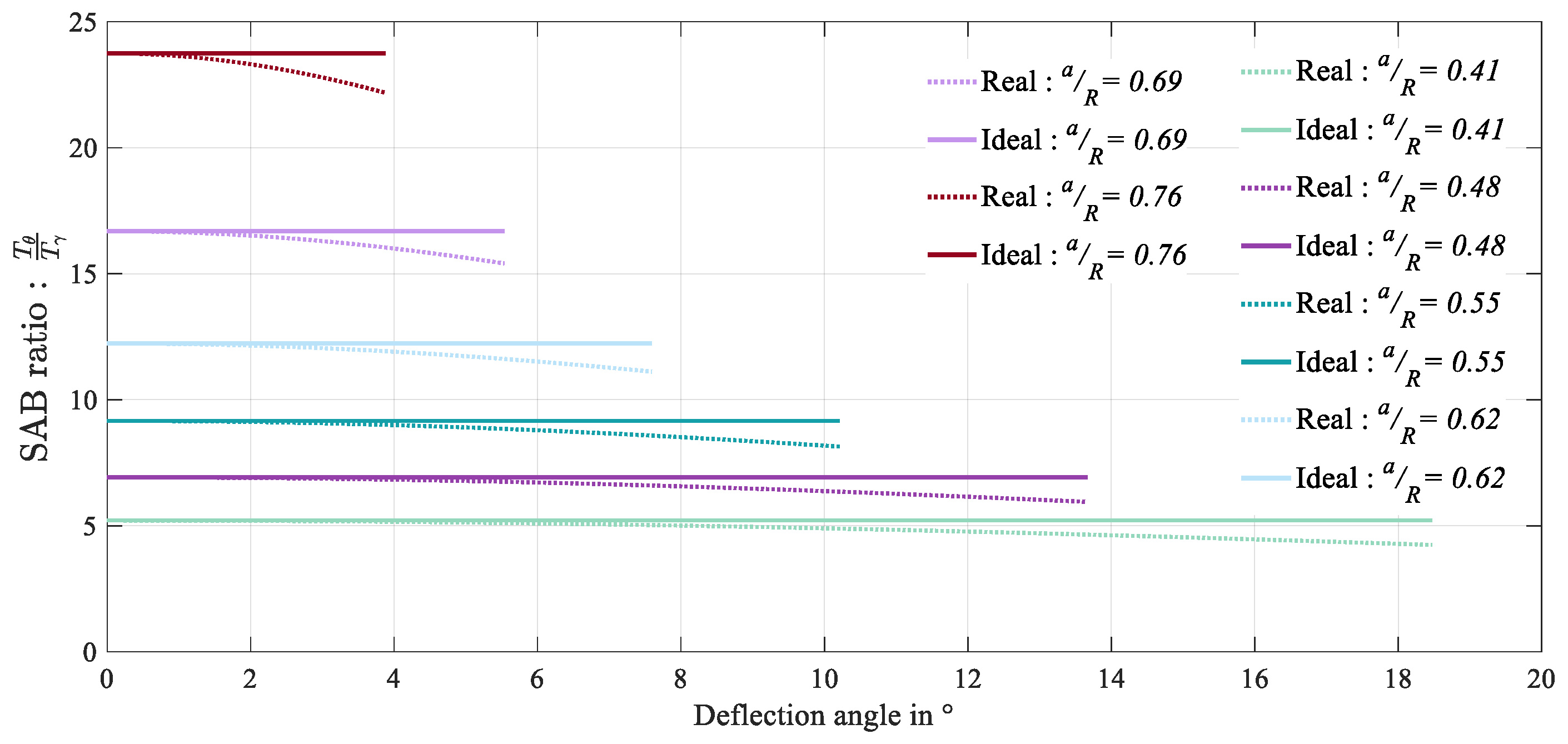
Figure 10 presents the real as well as ideal curves of the SAB’s reduction ratio given by Equations (15) and (16), respectively. The curves are computed for the numerical value , considered for illustration purposes. One can observe that in the vicinity of the zero-deflection value, the two curves overlap. This occurs for normal working conditions correlating with range (I) in Figure 8. Beyond the zero-deflection value, the system toggles to the range (II) and the two curves slightly split up. The approximation formula of the reduction ratio, , meets well the real curves under normal working conditions. In addition, one observes the possible tunability through parameter . The only drawback lies in the fact that the curves split up, which can be avoided, as explained in the next section, with a correction on the profile of the cam.
3. V2SOM’s Prototype
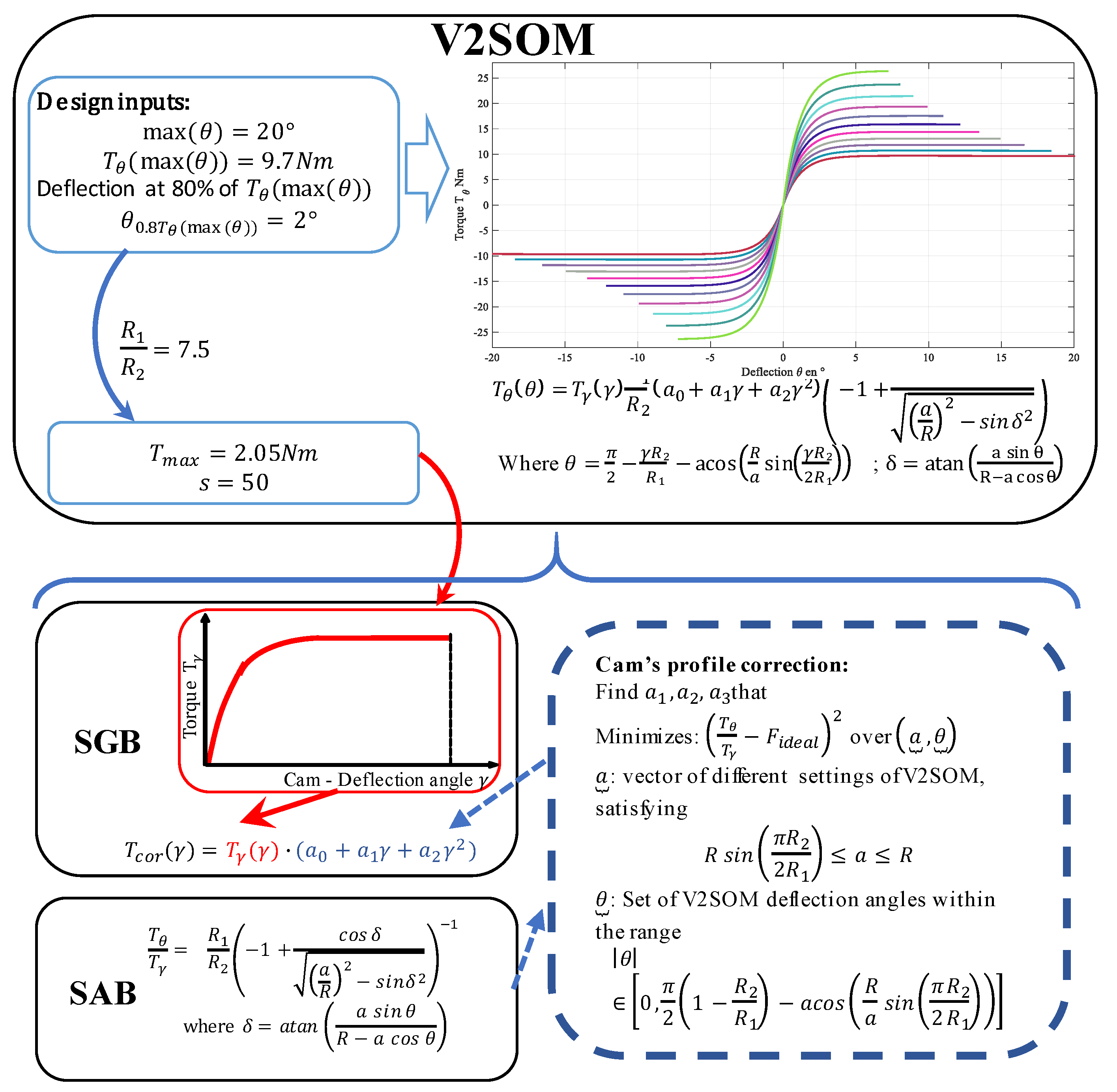
In the previous sections, we presented the two functional blocks and concluded that in order to get the overall ideal approximation of the SAB, the cam’s profile must be corrected. This change compensates for the declining trend of the reducer’s ratio, thus making the SAB behave as a continuously tunable quasi-linear reducer. The cam’s profile originates from the expression in Equation (14) which is corrected with a second-order polynomial factor, resulting in as follows:
With , and are real coefficients. The second-order polynomial factor is chosen in a way that the value is modified only in the range (II) while the continuity between the two deflection ranges is preserved. This is done with a simple optimization based on the least squares method, where the error is the difference between a set of points representing the real SAB characteristic and their ideal matching set. Figure 11 summarizes the design methodology of V2SOM.
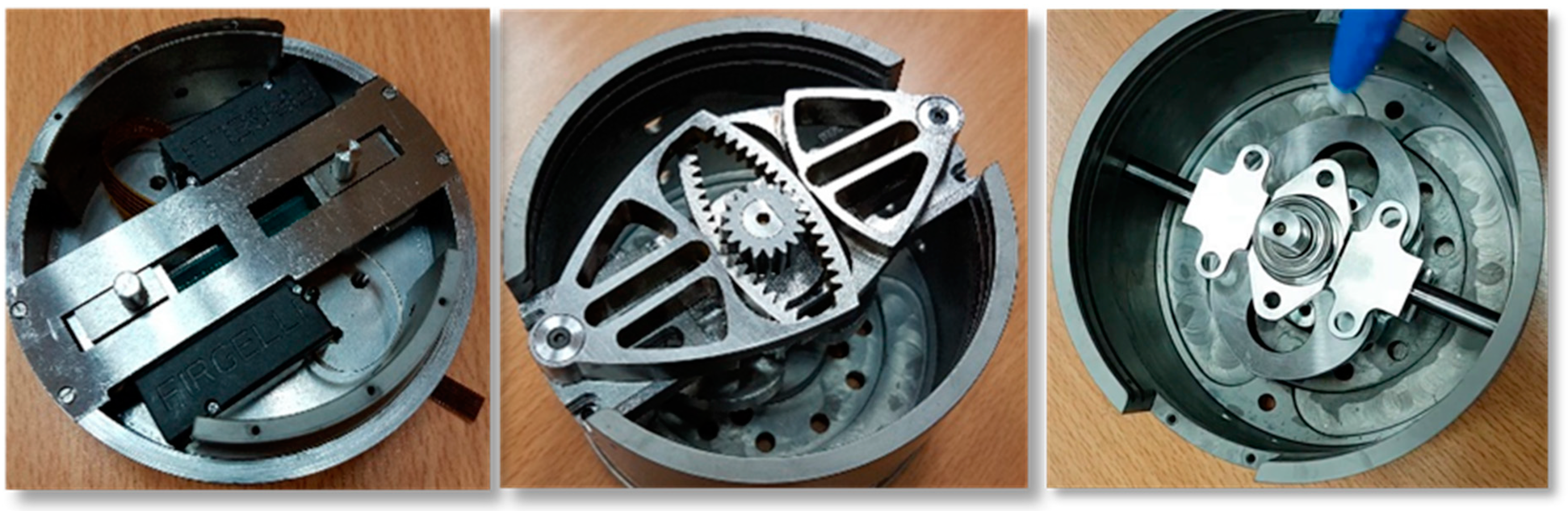
The V2SOM prototype was developed with its two functional blocks as illustrated in Figure 12. Two miniature linear motion actuators (Series PQ12, [23]) were used in the upper block. These compact, miniature-sized actuators present the following characteristics: maximal speed (no load), 9 mm/s; stroke, 20 mm; and maximal force, 35 N. The considered parameters of the torque curve vs. deflection, corresponding to the theoretical curve shown in Figure 8, are and . The real coefficients of the second-order polynomial obtained through optimization process and handled in the cam design are .
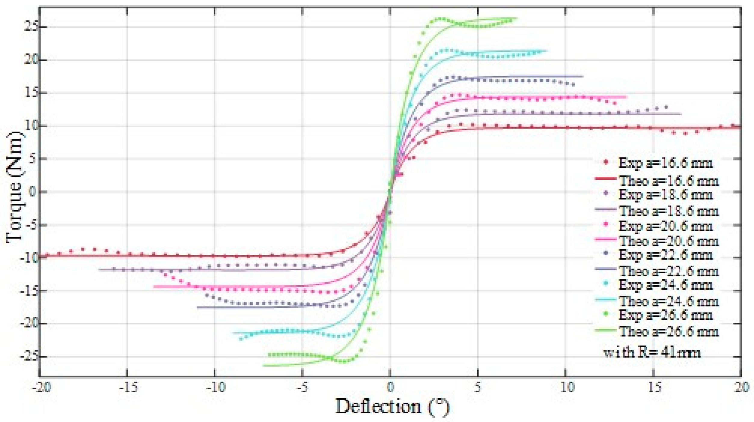
Figure 13 shows the theoretical curves (solid line) which maintain a relatively constant threshold in the range (II). This indicates the quality of the correction brought to the cam’s profile. The experimental curves show a slight deviation from their corresponding theoretical ones that is due to the imperfection of mechanical parts (e.g., natural friction phenomenon). Overall, a practically good match can be concluded as the crucial deflection range (I) shows a good match and the collision range (II) slightly deviates from its theoretical value. The presented V2SOM prototype has a cylindrical volume of 92 mm in diameter and 78 mm in height, as shown in Figure 3.
4. Performance Evaluation: V2SOM vs. Constant Stiffness
In this section, a comparison between V2SOM vs. a tunable constant stiffness profile is carried out on the choice of both HIC and ImpF criteria via simulation, as quantitative evaluation. A mechanical model of HR shock [10,17] is considered and implemented under a Matlab/Simulink platform for this purpose.
4.1. Safety Criteria
The safety of pHRI is quite problematic, particularly in terms of quantification as well as its validity to the whole-body regions. The most widely considered safety criteria include, but are not limited to, the following:
- ImpF (also known as contact force): this criterion is quite interesting as it can be applied to the whole-body regions. The contact force value is computed for a specific contact surface with a minimum 2.70 cm² area.
- Compression criterion (CompC): this criterion reflects a damaging effect of human–robot (HR) collision by means of a deformation depth, mainly considered for the compliant regions such as chest and belly.
The head region is the most critical part of the human body compared to the trunk region which is naturally compliant. The CompC criterion is not relevant for the head region as the skull is quite rigid. In contrast, HIC and ImpF are considered for their complementary aspect of HR shock evaluation. HIC is suitable for internal damage evaluation as it quantifies dangerous brain concussions, while ImpF is suitable for external damage evaluation. The collaborative workspace should be designed, as noted in ISO/TS15066 permits, in a way that free head motion cannot be compromised as the first step to guaranteeing safe pHRI.
4.2. Human–Robot Collision Model
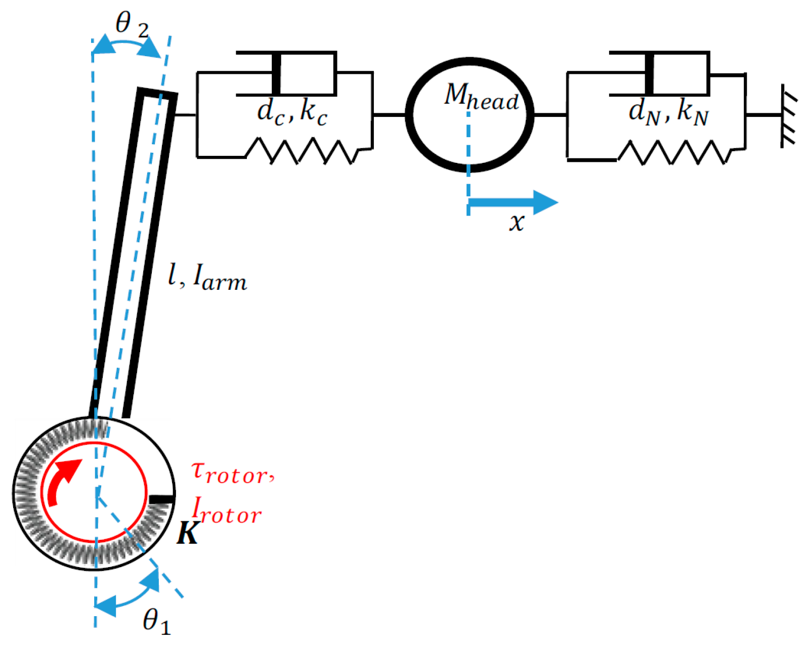
The most critical body region, as investigated in the literature [17,18], is still the human head from the perspective of safety problems. With respect to that investigation, a theoretical modeling of a dummy head hardware in a crash test was proposed and validated experimentally. The mechanical model is shown in Figure 14 and parameterized according to [10]:
- Neck viscoelastic parameters , ;
- Head’s mass and linear displacement ;
- Contact surface viscoelastic parameters , ;
- Robot arm contact position and inertia ;
- Rotor inertia , torque and angular position ;
- Stiffness of the variable stiffness mechanism K and angular deflection .
Both criteria, ImpF and HIC, are deduced from the collision model. The first one, ImpF, is obtained from simulation data as the applied force on the contact surface. The second one, HIC, is computed as a result of the following optimization problem:
where is the head acceleration value at instant t.
4.3. Simulation Results of HR Collision
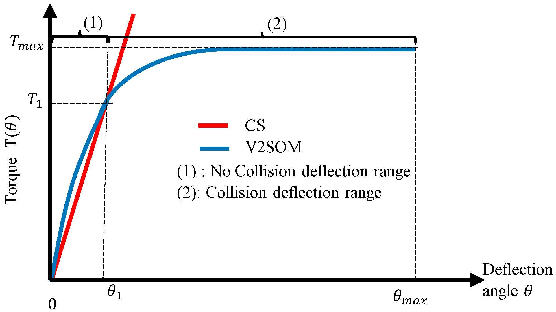
In the ensuing analysis, a comparison between V2SOM and a constant stiffness (CS) VSM was performed through simulation of the HR collision model under Matlab/Simulink. An identical elastic deflection value was considered for CS and V2SOM deflection at 80% of . This torque value defines the deflection range of the normal working mode for the V2SOM after which the shock absorbing mode is triggered. The shock absorbing mode is triggered when the torque reaches value (see Figure 15). In this case, the springs are compressed by the followers’ displacement as a result of the cam rotation (as shown in Figure 5 and Figure 6).
The simulation aims to emphasize the decoupling capability of V2SOM along inertia and torque in comparison to an equivalent CS-based variable stiffness mechanism.
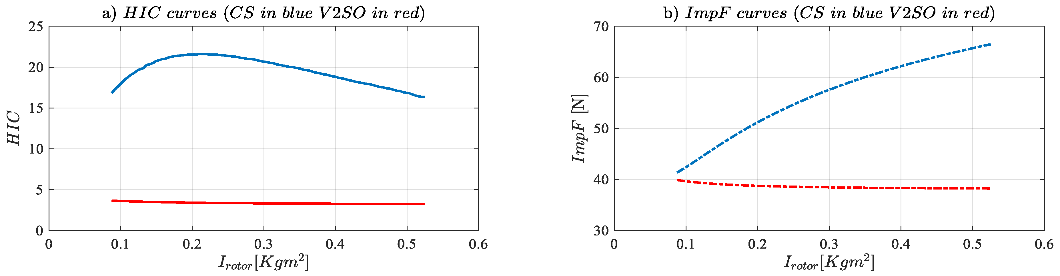
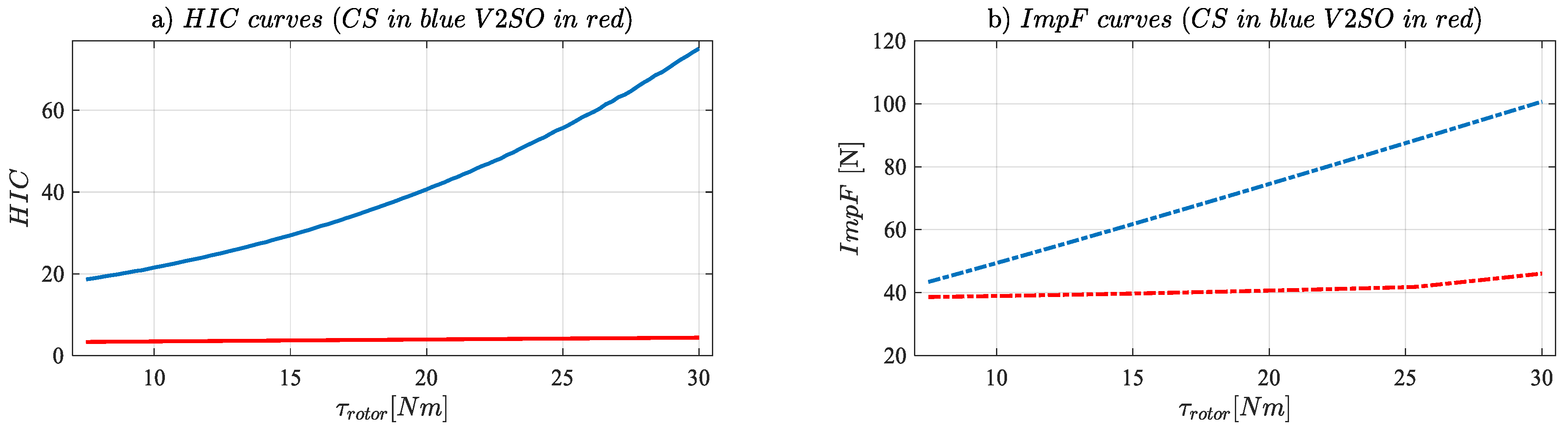
Inertia decoupling. The obtained results given in Figure 16 show that V2SOM presents more than an 80% improvement for the HIC criterion compared to CS. On the other hand, an improvement from 10% up to 40% is observed on the ImpF curves. and curves are still stable for a large range of rotor inertia. One can conclude from these results that V2SOM presents a high inertia decoupling capability compared to a CS-based variable stiffness mechanism. This characteristic means that in the case of HR collision, the human body sustains only arm side inertia rather than the heavy resulting arm and rotor inertia.
Torque decoupling. The obtained results given in Figure 17 show quasi-constant curves for V2SOM. The variation of motor applied torque does not affect the two criteria values, HIC and ImpF. An improvement of 10% up to 40% is observed for V2SOM for the ImpF criterion. This outcome is alleviated by the HIC values which confirm the torque decoupling capacity of a V2SOM similar to elastic behavior.
5. Conclusion
This paper deals with the design methodology of the variable stiffness safety-oriented mechanism (V2SOM). This new device, as its name indicates, comes to ensure the safety of physical human–robot interaction (pHRI) as well as to reduce the dynamics’ drawbacks of making robots compliant. Due to its two continuously linked functional modes, high and low stiffness modes, this novel device presents a high inertia decoupling capacity. The V2SOM mechanism’s working principle has been presented as well as its two functional blocks. The mechanical description of each block in addition to its mathematical models have been detailed. The interaction along the whole profile response between the two blocks has been discussed. Each block accomplishes a specific role, the first generating the desired stiffness profile through a cam-follower system and the second adjusting the stiffness profile through compact ring gears. The theoretical as well as the preliminary results of the first V2SOM prototype has been presented and discussed. Further experimental results will be addressed in future publications. The performance evaluation of V2SOM in terms of safety through an evaluation of safety criteria was performed. The impact force (ImpF) criterion and the head injury criterion (HIC) for external and internal damage evaluation of blunt shocks were considered, respectively.
Currently, a faster and lighter version of this device is under development, knowing that the current version weighs about 970 g with all its integrated control electronics.
Author Contributions
Conceptualization, Y.A. and M.A.L.; Data curation, Y.A. and M.A.L.; Formal analysis, Y.A.; Funding acquisition, M.A. and S.Z.; Investigation, Y.A., M.A.L., M.A. and S.Z.; Methodology, Y.A. and M.A.L.; Project administration, M.A.; Software, Y.A. and M.A.L.; Supervision, M.A.L. and S.Z.; Validation, Y.A., M.A.L., M.A. and S.Z.; Writing—original draft, Y.A. and M.A.L.; Writing—review & editing, Y.A. and M.A.L.
Funding
This research was funded by the French National Research Agency, convention ANR-14-CE27-0016, under the ANR project SISCob ‘‘Safety Intelligent Sensor for Cobots’’. This research was also supported by the French region ‘‘Nouvelle-Aquitaine’’ (program HABISAN 2015-2020) with the financial participation of the European Union (FEDER/ERDF, European Regional Development Fund).
Acknowledgments
This work was sponsored by the French government research program Investissements d’avenir through the Robotex Equipment of Excellence (ANR-10-EQPX-44).
Conflicts of Interest
The authors declare no conflict of interest.
References
- Khatib, O.; Yokoi, K.; Brock, O.; Chang, K.; Casal, A. Robots in human environments: Basic autonomous capabilities. Int. J. Robot. Res. 1999, 18, 684–696. [Google Scholar] [CrossRef]
- Tobe, F. Why Co-Bots Will Be a Huge Innovation and Growth Driver for Robotics Indus-try. Available online: http://spectrum.ieee.org/automaton/robotics/industrial-robots/collaborative-robots-innovation-growth-driver (accessed on 30 December 2015).
- De Santis, A.; Siciliano, B.; De Luca, A.; Bicchi, A. An atlas of physical human–robot interaction. Mech. Mach. Theory 2008, 43, 253–270. [Google Scholar] [CrossRef]
- Park, J.J.; Haddadin, S.; Song, J.B.; Albu-Schäffer, A. Designing optimally safe robot surface properties for minimizing the stress characteristics of human-robot collisions. In Proceedings of the 2011 IEEE International Conference on Robotics and Automation, Shanghai, China, 9–13 May 2011; pp. 5413–5420. [Google Scholar]
- Fritzsche, M.; Elkmann, N.; Schulenburg, E. Tactile sensing: A key technology for safe physical human robot interaction. In Proceedings of the 6th International Conference on Human-Robot Interaction (HRI’11), Lausanne, Switzerland, 6–9 March 2011; ACM: New York, NY, USA, 2011; pp. 139–140. [Google Scholar]
- Chiaverini, S.; Siciliano, B.; Villani, L. A survey of robot interaction control schemes with experimental comparison. IEEE/ASME Trans. Mech. 1999, 4, 273–285. [Google Scholar] [CrossRef] [Green Version]
- Bicchi, A.; Tonietti, G.; Bavaro, M.; Piccigallo, M. Variable stiffness actuators for fast and safe motion control. Robot. Res. 2005, 527–536. [Google Scholar]
- Grioli, G.; Wolf, S.; Garabini, M.; Catalano, M.; Burdet, E.; Caldwell, D.; Carloni, R.; Friedl, W.; Grebenstein, M.; Laffranchi, M.; et al. Variable stiffness actuators: The user’s point of view. Int. J. Rob. Res. 2015, 34, 727–743. [Google Scholar] [CrossRef]
- Jianbin, H.; Zongwu, X.; Minghe, J.; Zainan, J.; Hong, L. Adaptive Impedance-controlled Manipulator Based on Collision Detection. Chin. J. Aeronaut. 2009, 22, 105–112. [Google Scholar] [CrossRef] [Green Version]
- Gao, D.; Wampler, C.W. Assessing the Danger of Robot Impact. IEEE Robot. Autom. Mag. 2009, 16, 71–74. [Google Scholar] [CrossRef]
- Pratt, G.A.; Williamson, M.M. Series elastic actuators. In Proceedings of the 1995 IEEE/RSJ International Conference on Intelligent Robots and Systems, Human Robot Interaction and Cooperative Robots, Pittsburgh, PA, USA, 5–9 August 1995; Volume 1, pp. 399–406. [Google Scholar]
- Mathijssen, G.; Cherelle, P.; Lefeber, D.; Vanderborght, B. Concept of a Series-Parallel Elastic Actuator for a Powered Transtibial Prosthesis. Actuators 2013, 2, 59–73. [Google Scholar] [CrossRef]
- Zinn, M.; Roth, B.; Khatib, O.; Salisbury, J.K. A New Actuation Approach for Human Friendly Robot Design. Int. J. Rob. Res. 2004, 23, 379–398. [Google Scholar] [CrossRef] [Green Version]
- Wolf, S.; Grioli, G.; Eiberger, O.; Friedl, W.; Grebenstein, M.; Höppner, H.; Burdet, E.; Caldwell, D.G.; Carloni, R.; Catalano, M.G.; et al. Variable Stiffness Actuators: Review on Design and Components. IEEE/ASME Trans. Mechatron. 2016, 21, 2418–2430. [Google Scholar] [CrossRef]
- Ayoubi, Y.; Laribi, M.A.; Courrèges, F.; Zeghloul, S.; Arsicault, M. A Complete Methodology to Design a Safety Mechanism for Prismatic Joint Implementation. IEEE/RSJ Int. Conf. Intell. Robot. Syst. 2016, 304–309. [Google Scholar]
- Ayoubi, Y.; Laribi, M.A.; Zeghloul, S.; Arsicault, M. Design of V2SOM: The Safety Mechanism for Cobot’s Rotary Joints. In Mechanism Design for Robotics. MEDER 2018. Mechanisms and Machine Science; Gasparetto, A., Ceccarelli, M., Eds.; Springer: Cham, The Netherlands, 2019; Volume 66. [Google Scholar]
- López-Martínez, J.; García-Vallejo, D.; Giménez-Fernández, A.; Torres-Moreno, J.L. A Flexible Multibody Model of a Safety Robot Arm for Experimental Validation and Analysis of Design Parameters. J. Comput. Nonlinear Dyn. 2013, 9, 1–9. [Google Scholar] [CrossRef]
- Flacco, F.; de Luca, A. Residual-based stiffness estimation in robots with flexible transmissions. In Proceedings of the 2011 IEEE International Conference on Robotics and Automation, Shanghai, China, 9–13 May 2011; pp. 5541–5547. [Google Scholar]
- Cirillo, A.; de Maria, G.; Natale, C.; Pirozzi, S. A mechatronic approach for robust stiffness estimation of variable stiffness actuators. In Proceedings of the 2013 IEEE/ASME International Conference on Advanced Intelligent Mechatronics, Wollongong, Australia, 9–12 July 2013; pp. 399–404. [Google Scholar]
- Ayoubi, Y.; Laribi, M.A.; Arsicault, M.; Zeghloul, S.; Courreges, F. Mechanical Device with Variable Compliance for Rotary Motion Transmission, FR/IFBT17CNRCOB. 2017; France.
- Petit, F.; Friedl, W.; Hannes, H.; Grebenstein, M. Antagonistic Variable Stiffness Mechanism. Trans. Mechatron. 2015, 20, 684–695. [Google Scholar] [CrossRef]
- Eiberger, O.; Haddadin, S.; Weis, M.; Albu-Schäffer, A.; Hirzinger, G. On joint design with intrinsic variable compliance: Derivation of the DLR QA-joint. In Proceedings of the 2010 IEEE International Conference on Robotics and Automation, Anchorage, Alaska, 3–8 May 2010; pp. 1687–1694. [Google Scholar]
- Hyun, D.; Yang, H.S.; Park, J.; Shim, Y. Variable stiffness mechanism for human-friendly robots. Mech. Mach. Theory 2010, 45, 880–897. [Google Scholar] [CrossRef]
- Bicchi, A.; Tonietti, G. Fast and ‘soft-arm’ tactics. IEEE Robot. Autom. Mag. 2004, 11, 22–33. [Google Scholar] [CrossRef]
- Firgelli. Available online: http://www.firgelli.com (accessed on 5 January 2019).
Figure 1.
Variable stiffness actuator (VSA) scheme, including the actuation system coupled with a variable stiffness mechanism (VSM).
Figure 1.
Variable stiffness actuator (VSA) scheme, including the actuation system coupled with a variable stiffness mechanism (VSM).

Figure 2.
Architecture description: (a) Block representation of the V2SOM (b) Kinematic scheme in semi-view of the V2SOM.
Figure 2.
Architecture description: (a) Block representation of the V2SOM (b) Kinematic scheme in semi-view of the V2SOM.

Figure 3.
V2SOM: (a) 3D model, (b) CAD model of upper block, (c) CAD model of lower block, (d) prototype of upper block, (e) prototype of lower block, (f) first prototype.
Figure 3.
V2SOM: (a) 3D model, (b) CAD model of upper block, (c) CAD model of lower block, (d) prototype of upper block, (e) prototype of lower block, (f) first prototype.

Figure 4.
(a) Example of V2SOM basic torque curve with (b) QLCR. (c) Illustration of the V2SOM torque characteristic with seven QLCR settings.
Figure 4.
(a) Example of V2SOM basic torque curve with (b) QLCR. (c) Illustration of the V2SOM torque characteristic with seven QLCR settings.

Figure 5.
V2SOM working modes. (Left) Torque curve, (Right) stiffness curve.

Figure 6.
Stiffness generator block: (a) at rest ( =0), (b) at deflection ( ), (c) cam-follower contact surface geometric parameters, (d) cam-follower contact forces.
Figure 6.
Stiffness generator block: (a) at rest ( =0), (b) at deflection ( ), (c) cam-follower contact surface geometric parameters, (d) cam-follower contact forces.

Figure 7.
Spring setup in the lower block: (a) CAD model, (b) simple sketch and parameters.

Figure 8.
Torque vs. deflection characteristic of stiffness generating block and V2SOM’s two functional modes.
Figure 8.
Torque vs. deflection characteristic of stiffness generating block and V2SOM’s two functional modes.

Figure 9.
Stiffness adjusting block: (a) CAD model, cross-section view’ (b) simplified scheme with single ring gear.
Figure 9.
Stiffness adjusting block: (a) CAD model, cross-section view’ (b) simplified scheme with single ring gear.

Figure 10.
SAB ratio curves (dotted line) and their ideal approximation (solid line).

Figure 11.
Illustration of V2SOM’s design.

Figure 12.
V2SOM prototype with each two functional blocks: (a) SAB: stiffness adjusting block, (b) SGB: stiffness generator block.
Figure 12.
V2SOM prototype with each two functional blocks: (a) SAB: stiffness adjusting block, (b) SGB: stiffness generator block.

Figure 13.
V2SOM’s torque vs. deflection theoretical and experimental curves for the eleven different SAB settings.
Figure 13.
V2SOM’s torque vs. deflection theoretical and experimental curves for the eleven different SAB settings.

Figure 14.
Mechanical model of dummy head hardware collision against a robot arm.

Figure 15.
V2SOM and CS profile, .

Figure 16.
simulation results;

Figure 17.
simulation results; ; , (7.5→30, 15,12) ; ;

© 2019 by the authors. Licensee MDPI, Basel, Switzerland. This article is an open access article distributed under the terms and conditions of the Creative Commons Attribution (CC BY) license (http://creativecommons.org/licenses/by/4.0/).
Share and Cite
MDPI and ACS Style
Ayoubi, Y.; Laribi, M.A.; Zeghloul, S.; Arsicault, M. V2SOM: A Novel Safety Mechanism Dedicated to a Cobot’s Rotary Joints. Robotics 2019, 8, 18. https://doi.org/10.3390/robotics8010018
AMA Style
Ayoubi Y, Laribi MA, Zeghloul S, Arsicault M. V2SOM: A Novel Safety Mechanism Dedicated to a Cobot’s Rotary Joints. Robotics. 2019; 8(1):18. https://doi.org/10.3390/robotics8010018
Chicago/Turabian StyleAyoubi, Younsse, Med Amine Laribi, Said Zeghloul, and Marc Arsicault. 2019. "V2SOM: A Novel Safety Mechanism Dedicated to a Cobot’s Rotary Joints" Robotics 8, no. 1: 18. https://doi.org/10.3390/robotics8010018
Note that from the first issue of 2016, this journal uses article numbers instead of page numbers. See further details here.