
Tunable Vibration Absorber Design for a High-Precision Cartesian Robot


1
Department of Mechanical and Aerospace Engineering, Politecnico di Torino, Corso Duca Degli Abruzzi 24, 10129 Torino, Italy
2
Efort Europe S.r.l., Corso Duca Degli Abruzzi 2, 10128 Torino, Italy
*
Author to whom correspondence should be addressed.
Robotics 2022, 11(5), 103; https://doi.org/10.3390/robotics11050103
Submission received: 26 July 2022
/
Revised: 12 September 2022
/
Accepted: 20 September 2022
/
Published: 21 September 2022
(This article belongs to the Section Industrial Robots and Automation)
Abstract
:In metal sheet processing for automotive application, it is crucial to guarantee high robot dynamics for reduced cycle times and adequate components accuracy to be competitive in the market. Since the two aspects are closely and inversely related, the problem becomes challenging. After the first cutting tests, the Cartesian Robot prototype displayed insufficient dimensional accuracy when undergoing high accelerations. The solution hereby proposed is the design of a Tuned Mass Damper (TMD), working in shear mode, to reduce the robot vibration amplitude. To this end, an initial assessment of the robot frequency response and natural frequencies was performed both by using a Finite Element (FE) model of the machine and experimentally. Further, frequency response analyses were carried out to evaluate the TMD effectiveness and to highlight possible criticalities from the manufacturing point of view. On a numerical level, the proposed design can damp the machine resonant frequencies, also showing a certain grade of tunability before operation and in-plane orientation insensitiveness thanks to the use of cylindrically shaped springs.
1. Introduction
Vibrations and relative control strategies are a delicate and wide matter, especially when dealing with the dimensional accuracy of a component cut by an automated machine. No vibration control technique can be a priori defined better than another, and it strongly depends on the mechanical system being dealt with: application field, design requirements and constraints, project phase, cost-to-benefit ratio, and so on. Over the years, different control solutions have been developed and can be sub-divided into [1]: structural modification [2], material selection [3], vibration isolation [4], addition of vibration absorbers/neutralizers, vibration damping [5], and source modification [6].
The present paper deals with the unwanted vibrations and relative control strategy of a Computer Numerical Control (CNC) Cartesian robot prototype designed for metal sheet processing in the automotive field. A Cartesian robot displays a serial configuration of its three motors, in which each of them can perform a linear movement, i.e., prismatic actuator, thus creating a parallelepiped-shaped working volume. The structure can either be a cantilever beam or a Gantry/RAM one. A Cartesian robot offers some advantages: they are generally easy to design, install and maintain, display a high workspace-to-footprint ratio as well as flexibility, and have a simpler inverse kinematic solution. A closed form exists due to the presence of the linear axes. For the above-mentioned reasons, they find applications in different fields, such as Coordinate Measurement Machines (CMMs), machining, assembling, laser processing, and pick-and-place. Given the broadness of the matter, and the purpose of the present paper, the overview is limited to some key aspects of the multi-axis machining application, such as reduction of the cycle time and of the dimensional and geometrical tolerances. In particular, when undergoing high accelerations, a Cartesian robot may suffer from positional accuracy errors both due to axis error propagation and reduced stiffness, especially in cantilever structures and elevated moving masses. Widely used methods involve controlled approaches such as software modification, for example, optimal control methodology [7], modification for motion ramp generation [8,9], hardware modification of electric linear motors (e.g., flexible mounting [10]), and active and semi-active vibration absorbers. In addition, error compensation techniques [11], structural and topology optimization of load-carrying components, i.e., basement and column, by minimizing the strain energy or maximizing the eigenvalues [12,13,14], are the strategies typically used to face the previously-exposed issues. Alongside them, Tuned Mass Dampers (TMDs) have found application in the robotics field as well [15,16,17,18], Multi-TMD applications can be found mainly for chatter mitigation [19,20,21] and to reduce vibrations of structures with varying dynamics [22]. After the first cutting test performed on the real prototype, it was quite evident how the high impulse forces arising from the electric motors excited the machine resonant frequencies, thus leading to unacceptable components quality.
The solution hereby proposed is the design of a TMD, working in shear mode, able to exploit some of the characteristics of the modes of the structure to provide a simple yet effective improvement. A TMD is a mechanical device useful for the vibration control of a structure. In its simplest form, it consists of a mass and a spring sized in such a way that its natural frequency is close to or better tuned to the one of the structure that has to be neutralized. Since the two sub-systems are elastically coupled, the motion of the TMD is wide enough to produce inertia forces that perfectly balance external excitations acting on the structure, thus resulting in a null movement of the structure at that frequency. The strong limitation is that it works perfectly fine in a narrow frequency band. The use of an additional damper for the vibration absorber allows reducing vibrations on a slightly wider one [23]. Consequently, the simultaneous management of more than one mode is not immediate if a proper design is not carried out. The TMD was first patented by German engineer Frahm in 1911 [24]. From that moment, a great development was carried out both in mechanical and civil engineering. Den Hartog developed a closed-form solution for the optimal selection of frequency ratio ropt and damping ratio ξopt as a function of the mass ratio μ for an undamped single-DoF system for the case of mass excitation or base excitation [25]. Rana and Soong proposed a parametric study investigating the effect of detuning, as well as a simplified design approach and example for the application of a TMD on a particular mode of a multi-DoFs system [26]. Optimal design methods to control vibrations arising from different sources were investigated [27], as well as different optimization criteria to be applied in the design of a dynamic damper [28], and different numerical approaches were developed, such as Genetic Algorithms (GA), particle swarm [29] or global optimization algorithm EVOP [30]. Passive dynamic dampers are the most consolidated ones, even though in recent years, alternative practical designs such as the inerter-based ones [31] have found application as well as the Coupled TMD for the simultaneous management of more than one mode [32]. Along with the passive technology, adaptive TMDs [33,34] were also developed in order to eliminate the above-mentioned narrow frequency-band limitation and allow a frequency shift of the mechanical device over a certain domain. This solution may be quite useful in mechanical systems in which either mass/inertia or stiffness change over time as the system natural frequencies get consequently modified. The proposed design is a single Degree of Freedom (s-DoF) TMD. Differently from previously analyzed solutions, it presents cylindrically shaped springs, in a parallel configuration and working in shear mode. This design choice guarantees the same stiffness independently of the angular coordinate. This feature allows for simultaneous vibration control along different oscillation directions at a specified frequency, thus also resulting in an additional degree of flexibility for mounting. Tunability before operation is possible by the addition of small masses.
This paper is organized as follows. Firstly, the Cartesian robot prototype description and assessment through the outputs of experimental tests and modal and frequency response FEM analyses are proposed. In Section 3, a practical design procedure is presented together with a frequency response parametric analysis as a function of the dynamic damper mass and stiffness distribution. In the last part of this section, possible criticalities using a simplified numerical model are evaluated. In Section 4, conclusions and possible developments are highlighted.
2. CNC Robot
2.1. Robot Description
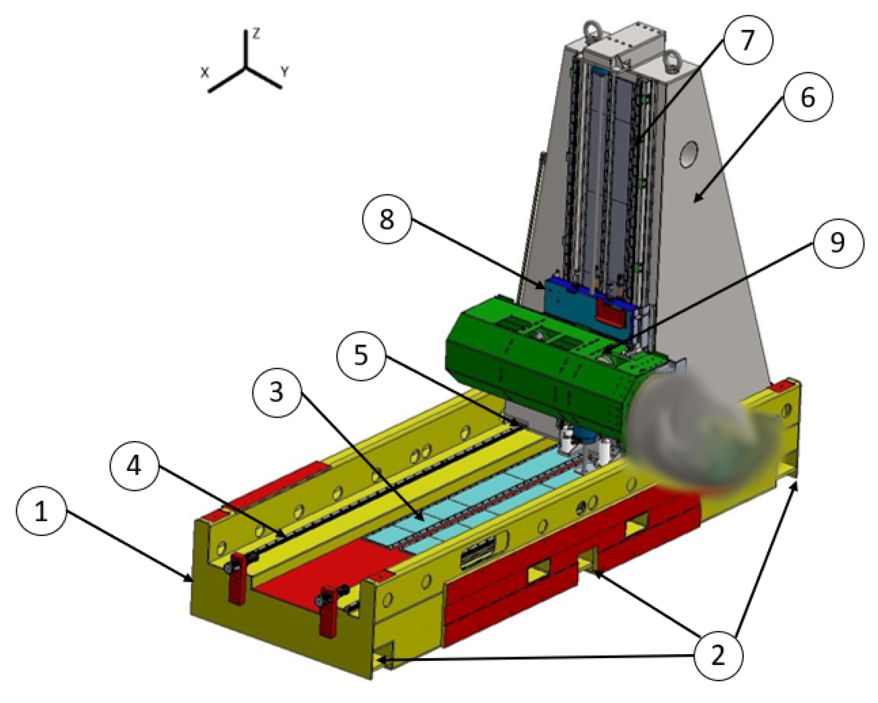
The robot object of the present paper was born to perform rapid movements for metal sheet cutting in the automotive field. Being an innovative machine, still in the prototype phase for which design confidentiality applies, a complete description is not provided. Nonetheless, it can be considered as a robot composed of a “host machine”, i.e., a Cartesian robot that translates the “head” in the space. The head can perform the required rotations to completely define the position and attitude of the end-effector, with a certain grade of redundancy. This kind of design guarantees the machine to really be competitive on the cycle time, even though the linear axes do not show particular differences with respect to the benchmark because the slow movements of the heavy components are reduced to a minimum by an intelligent coordination of the machine axes. In Figure 1, an illustration is presented. Due to its innovative and alternative design, the “head” cannot be shown, which is why a portion of Figure 1 is blurred.
The machine presents a welded steel basement (1), constrained to the ground on six points by means of M20 screws (2). On the basement, magnetic plates (3) and tracks (4) are screwed. The movement of the prismatic column (6) is allowed by the magnetic interaction between the electric linear motors, located at its bottom and not visible in Figure 1, and the magnetic plates (3). The six slides screwed under the column (5) create a shape coupling with the basement tracks (4), thus allowing a precise guiding system. The movement along the Z axis can be performed by the Z-Carriage (8) based on the same actuation principle as already exposed and guided by the column tracks (7). Six slides, not visible in the figure, are used also in this case and screwed on the back surface of the Z-Carriage. The movement along the Y direction is performed by the Y-Group (9), protected and sustained by a steel cover, on which two tracks and magnets are screwed. In this case, the motor allowing the movement is mounted on the Z-Carriage, and the slides used are four. In Table 1, moving masses, motor forces, and kinematic parameters are listed for each direction. Particularly, it provides an indication of the mass that must be moved along the specific direction, the nominal and peak force the motors are able to provide along that direction and, consequently, the maximum acceleration the system can reach. The stroke is a design constraint connected to the working volume that must be reached, a function of the workpiece dimensions. Given the maximum acceleration, stroke, and by assuming a triangular velocity profile, the maximum speed for each direction is reported as well.
2.2. Cutting Test and Experimental Dynamic Evaluation
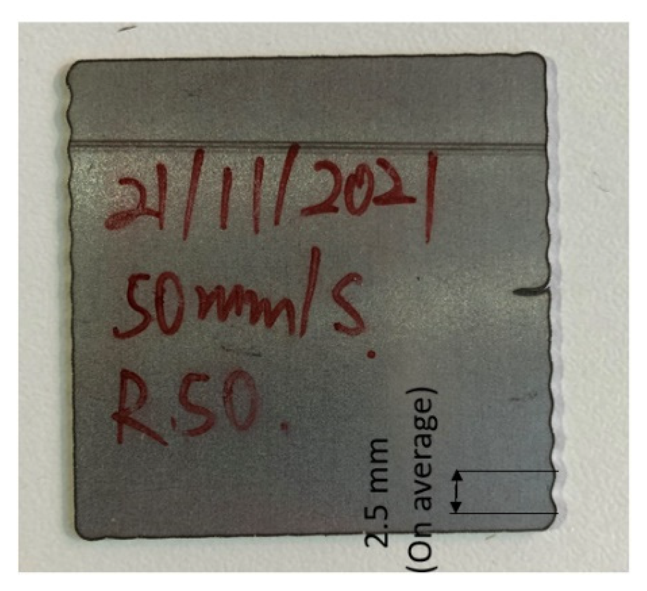
Figure 2 displays a sample cut by the machine during the first cutting test. It may be observed that the cut is not straight; rather, some oscillations are present. It is evident how the oscillation of the end-effector has a higher impact in correspondence with the direction changes, getting damped as it advances.
A preliminary analysis identified the problem in the fact that the change in direction, made possible by the acceleration of a different axis, led to impulse forces exciting the machine natural frequencies. These oscillations were quite visible during the machine working at maximum performances. Moreover, analyzing the cutting edges in Figure 2, an indirect frequency oscillation estimation can be carried out to obtain a first approximation of its value. The average distance, dmean, between two peaks is around 2.5 mm. Given the cutting speed, vcut, equal to 50 mm/s, the frequency estimate, fest, can be computed as:
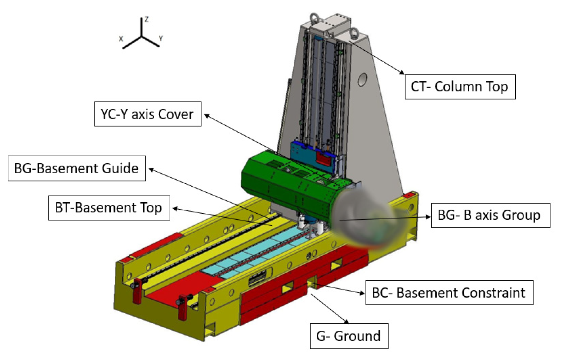
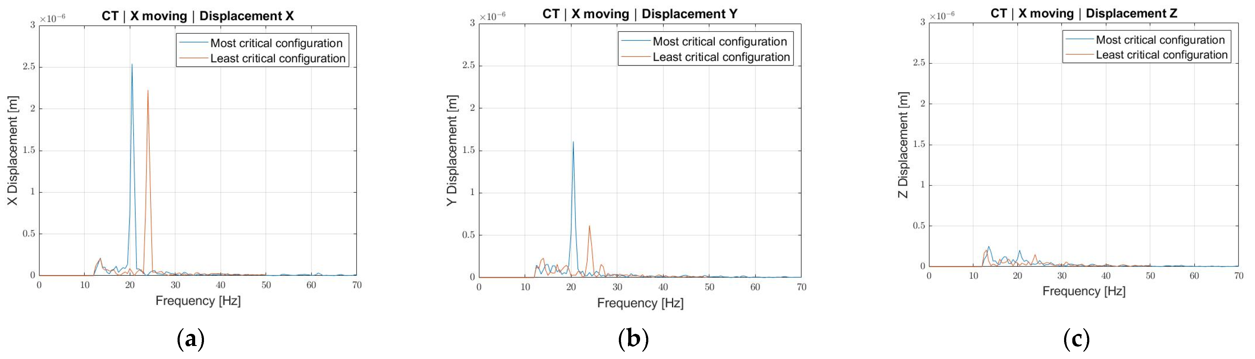
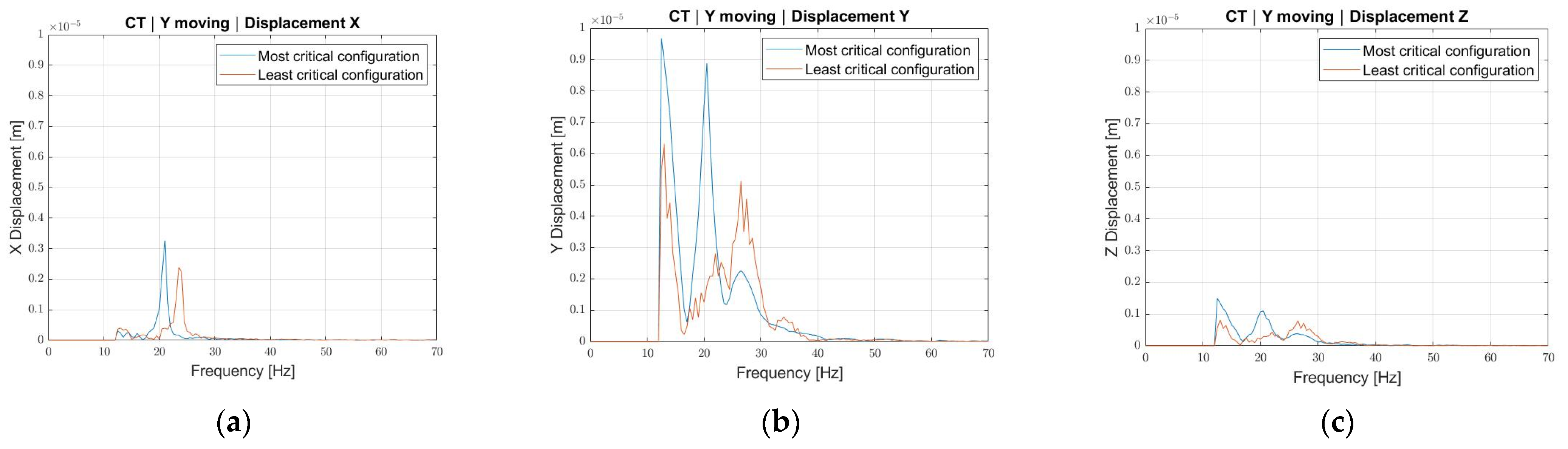
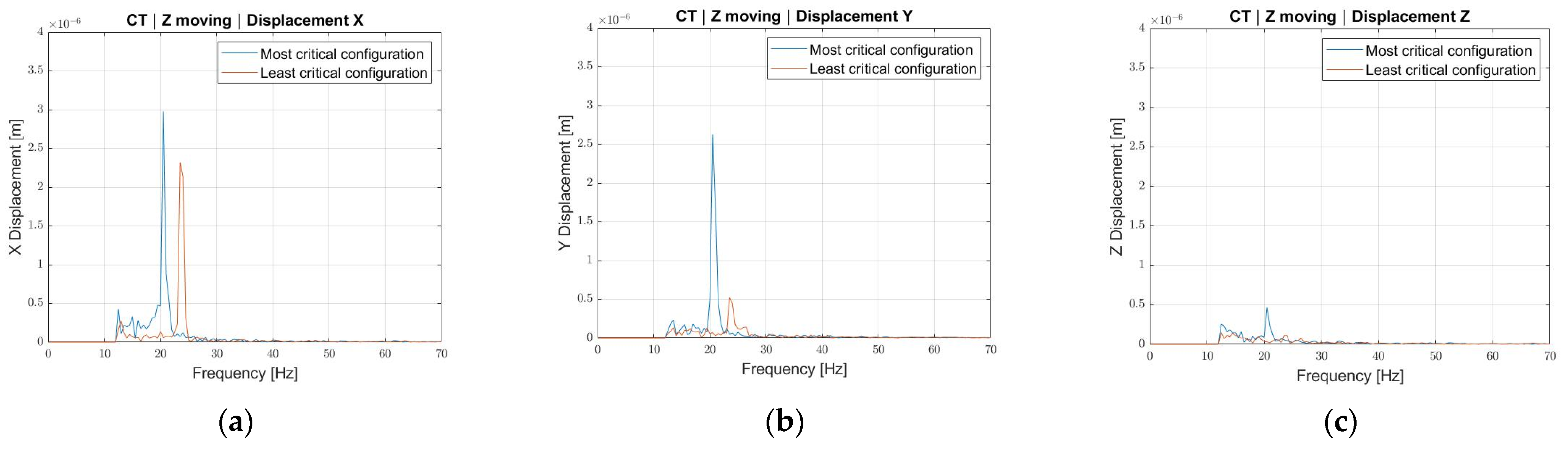
The low-frequency value appeared to be consistent with the oscillation frequency of a mechanical system, a hypothesis initially confirmed by the indications of the control system. In particular, the reconstructed signal relative to the square trajectory of Figure 2, measured by the position transducer of the linear axes, did not show any significant position error oscillations, thus confirming the oscillation was taking place independently of the control system and confirming the mechanical nature. Therefore, additional measurements were performed with the aim of evaluating the displacement response frequency spectrum. They were carried out using Sequoia FastTracer, a triaxial MEMS accelerometer, allowing a maximum sampling frequency of 2500 samples/s per channel, with a dynamic output of ±5 g, whose axes were oriented along those of the machine. The single measurement consisted in providing a single impulse acceleration on a single axis and then recording the data arising from the accelerometer applied at a specific point. The measurements were repeated in the same way, for each of the seven measuring points, indicated in Figure 3 as: Ground (G), Basement Constraint (BC), Basement Top (BT), Basement Guide (BG), Column Top (CT), Y axis Cover (YC), and B axis Group (BG) and for each of the three different axes accelerations. On top of that, they were performed by considering the machine in the most critical configuration, namely Z and Y axes at their stroke ends, and the least critical configuration, namely Z and Y axes at their stroke starts. The reason behind this choice was to understand how much the robot resonant frequency could vary in these limit positions. For the sake of conciseness, only the measurements of the Column Top (CT) point are reported (Figure 4, Figure 5 and Figure 6) for each motor impulse, in a comparison between the most (stroke end) and least (stroke start) critical configurations.
- As expected, the machine presents a resonant frequency shift between the most critical configuration, 20 Hz, and the least one, 24 Hz. This happens because the moment of inertia with respect to the constraint, i.e., the column base, reduces as the masses are closer to it.
- The 20 Hz frequency always shows a higher displacement with respect to the 24 Hz one, even though along the X direction, for each axis movement, the displacement difference is not remarkable. This may be because the oscillation along the X direction is a consequence of the column bending about the Y axis. The bending about the Y axis depends on the distance between the column constraint, i.e., the slide, and the center of mass position of the Y-Group along directions Z and X. When the Y-Group is at its stroke start, the distance between center of mass and slide reduces in the Z direction, thus inducing a change in frequency, but the distance between center of mass and slide along the X direction remains unchanged, thus keeping a relatively high oscillation amplitude.
2.3. Machine Modal and Frequency Response FEM Analysis
To further investigate the problem from the dynamic standpoint, a Finite Element (FE) model of the complete machine was created in the MSC Apex Computer-Aided Engineering (CAE) environment. Surface, tetra, and hexa elements were used depending on the component to find a proper balance between modeling accuracy and computation time. A comparison between the complete model and a reduced one was carried out to reduce the simulation time. The reduced model (Figure 7) differs from the original one for the representation of the Y-Group and the head, which are substituted by a concentrated mass and inertia. The concentrated mass and inertia, which take into account both the arm of the robot, the spindle, and the head, are connected to the Z-Carriage by means of rigid connectors. Moreover, the software gives the possibility to precisely indicate where to locate the concentrated mass and inertia, which, in this case, were placed in the center of mass of the replaced sub-unit. The value of concentrated mass and inertia were derived from CAD evaluation, after the exact material was assigned to each component. As previously stated, a complete model was created, and the decision to perform the analyses on the reduced one is mainly related to the fact that no relevant differences are present between the outputs of the two models, mainly because the Y-Group is much more rigid with respect to the mass it had to bear. On top of that, the reduced model allows for a simulation time reduction of 30% with respect to the complete one.
2.3.1. Modal Analysis
Initial modal analyses were performed to identify possible model criticalities and simplifications. The machine was modeled in its most critical configuration; therefore, modal frequencies in the range of 20 Hz were expected according to the outputs of the experimental measurements. This was not the case after the first trial, where the machine global natural frequencies resulted to be higher. Hence, a model tuning was necessary to identify and correct the stiffening arising from the incorrect modeling choices. In particular:
- A constraint sensitivity analysis was run on the basement constraints. The output frequencies were dependent on the constraint condition. In the initial configuration, a displacement constraint was directly applied to the surface area corresponding to the screw under-head. In the final model instead, a part of the screw was modeled as well, by considering the part emerging from the ground as a cantilever beam, connected in turn to the basement hole by means of an RBE3 connection.
- Flexible beam elements with RBE3 node distribution were used, instead of rigid beams with RBE2 distribution, to model the screws between tracks and basement, slides and column, and tracks and column.
The combination of the two mentioned changes led to a frequency reduction of up to 30% for the most relevant modes. In addition to this, the modal analysis of the complete model was run to identify which were the modes and natural frequencies characterizing the structure on the 10 lowest ones. The Effective Mass Fraction (EMF) [35,36] was used to:
- Evaluate if the 10 modes are sufficient to completely characterize the structure from a dynamic point of view. In general, if the sum over the modes of the EMFs for each direction falls around 80–90%, there is no need to consider higher-order modes.
- Define which modes are relevant, since the EMF provides an indication of the energy associated with each mode. In Table 2, the effective mass fraction is reported as a function of the mode number and displacement direction. In this case, six modes were considered as global ones, namely Mode No. 1–8, because they have a non-negligible (<10−1) EMF along a particular direction.
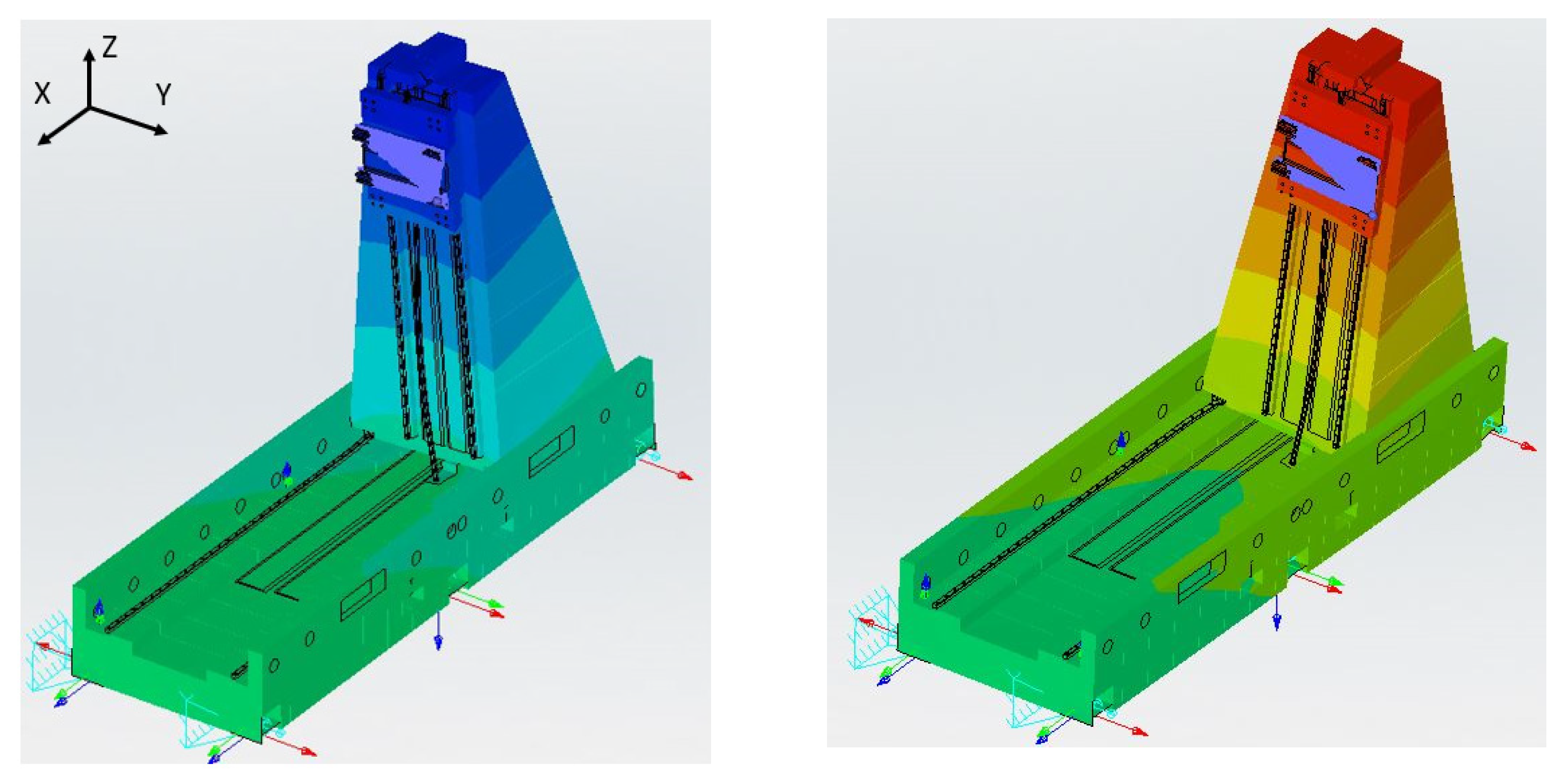
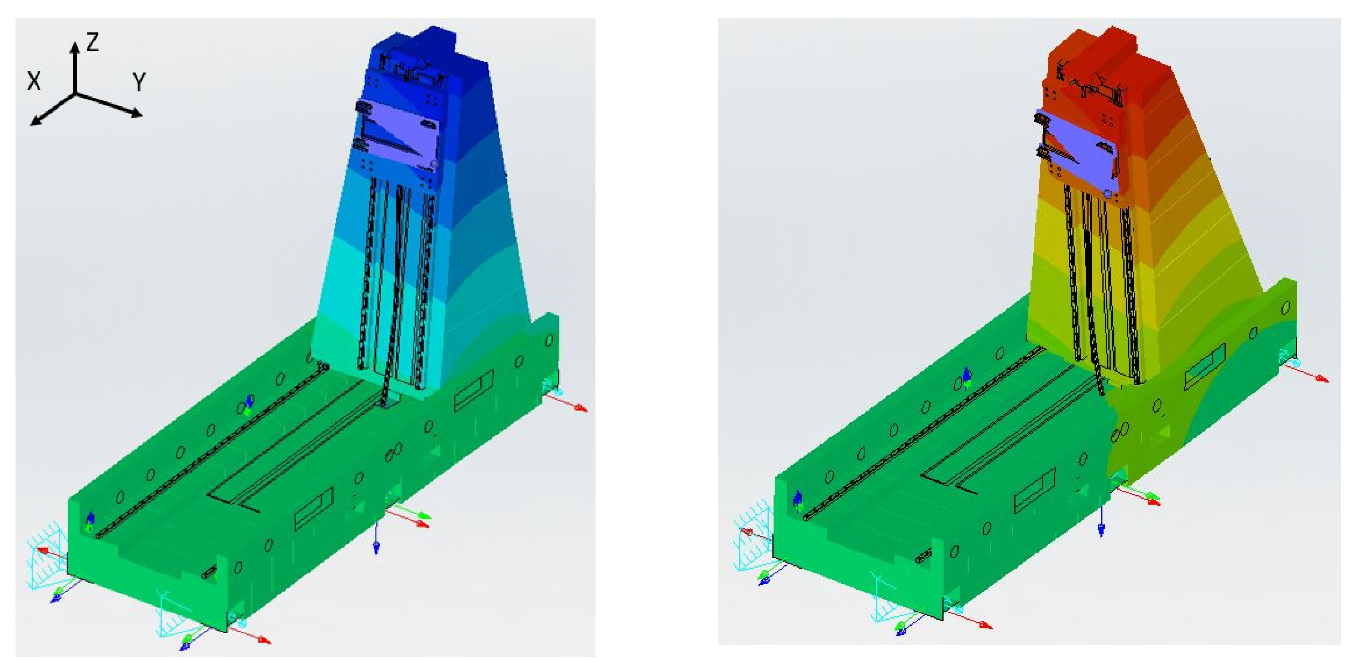
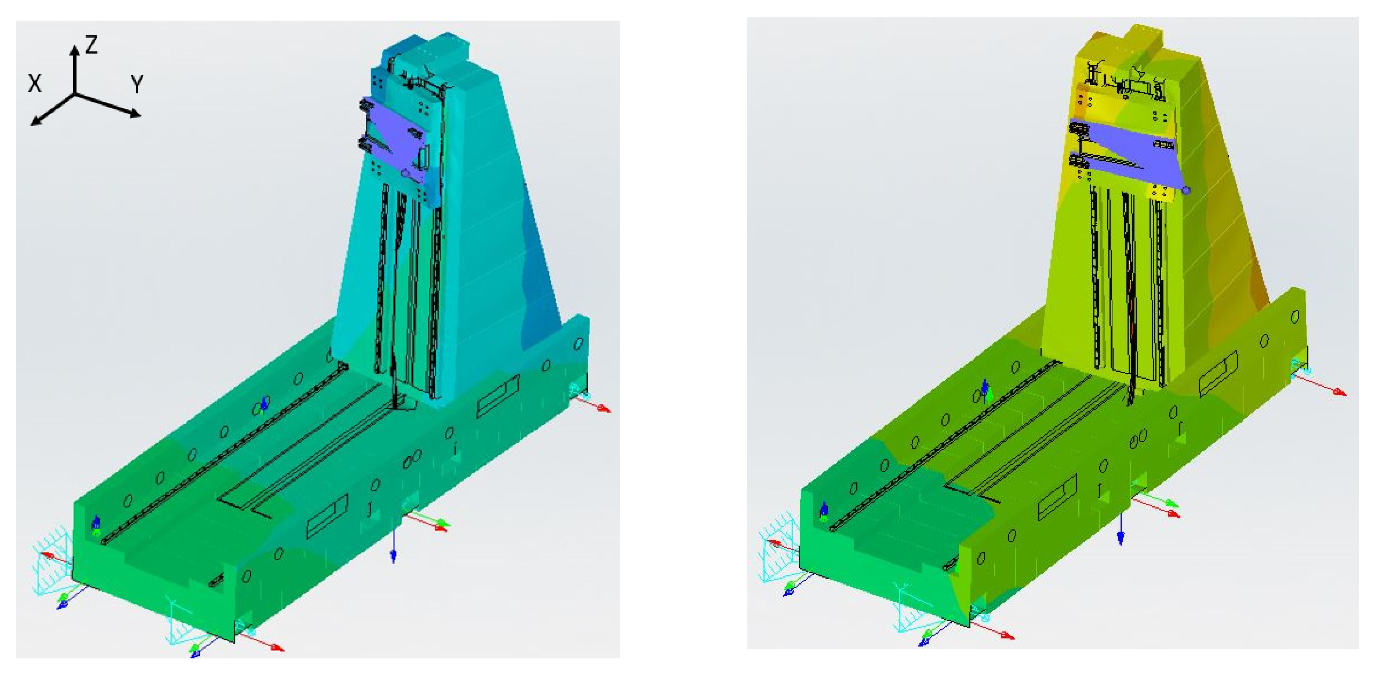
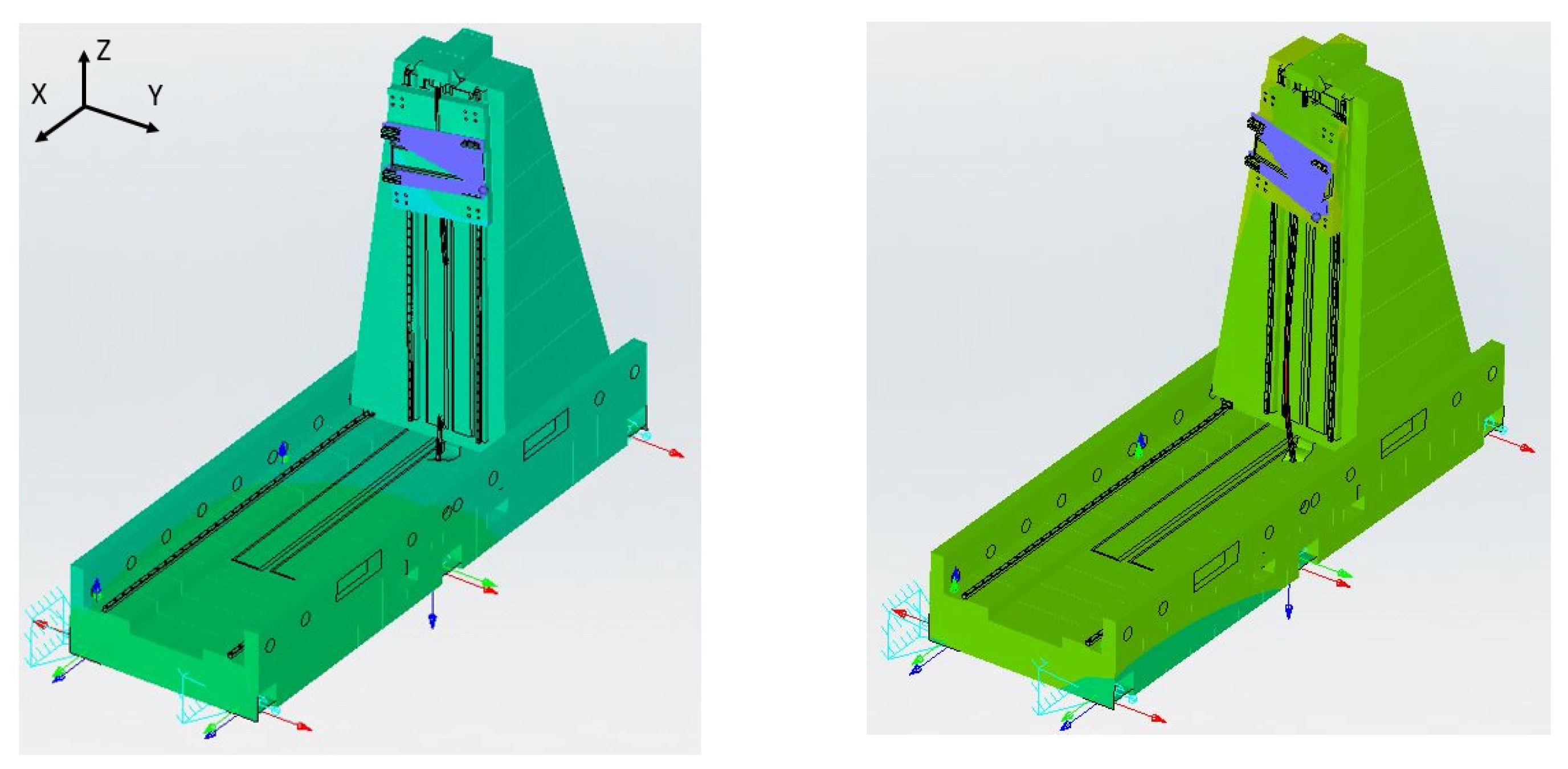
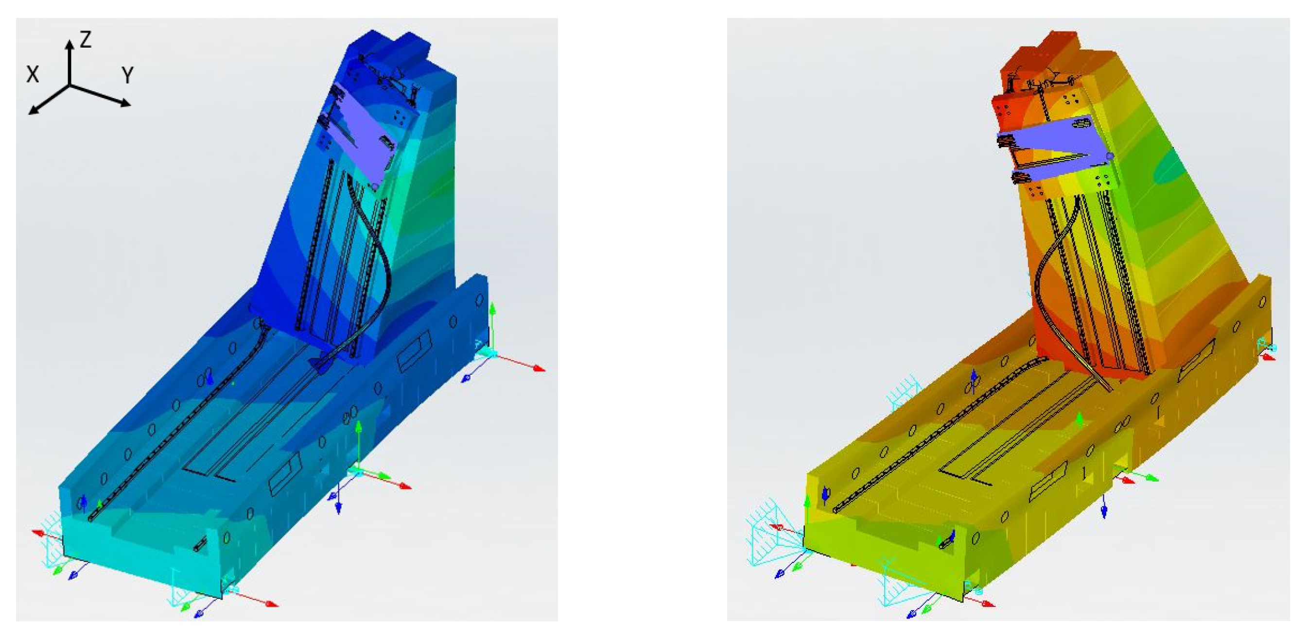
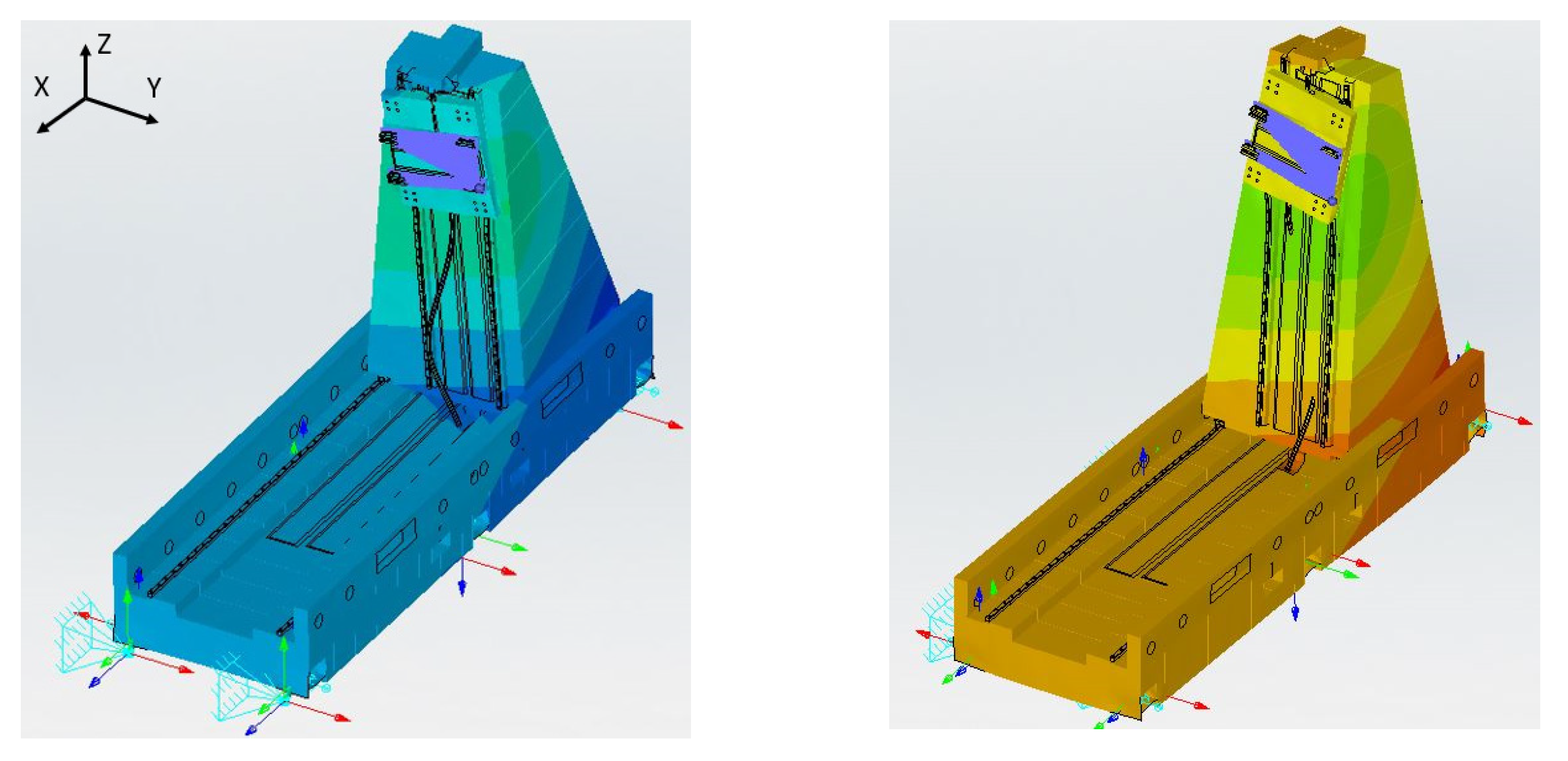
In Figure 8, Figure 9, Figure 10, Figure 11, Figure 12 and Figure 13, a graphic representation of the global modes is depicted. As it is possible to notice, the first two modes represent a pure column bending about the X and Y directions, respectively. They are not only quite close to the 20 Hz value, but they also have the highest percentage of EMF along the Y direction and X direction, respectively. This consideration is consistent with the experimental evaluation, even though a certain error margin is present. It is true that there is not a unique mode, but both are close to the value of interest and show a displacement along the same directions found in the experiments. The higher-order frequencies lead to more complicated modal shapes. These considerations result to be quite an important feature of the system and were exploited for the design of the dynamic damper since:
- The low-frequency modes are the critical ones during operation, as confirmed by experimental characterization, i.e., cut samples and dynamic measurements;
- A single mass damper can provide a fast and efficient solution for the simultaneous vibration control of both modes since they are close in frequency;
- The maximum oscillation amplitude of the first two modes is in correspondence with the column top;
- The column top provides enough space to host the dynamic damper without inducing heavy design modification on the already existing prototype.
Therefore, the further analyses to design the damper were focused on the first two modes.
2.3.2. Frequency Response Analysis
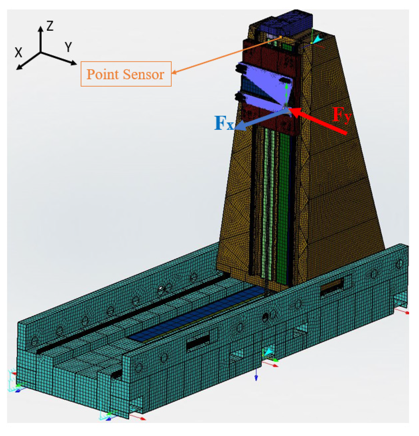
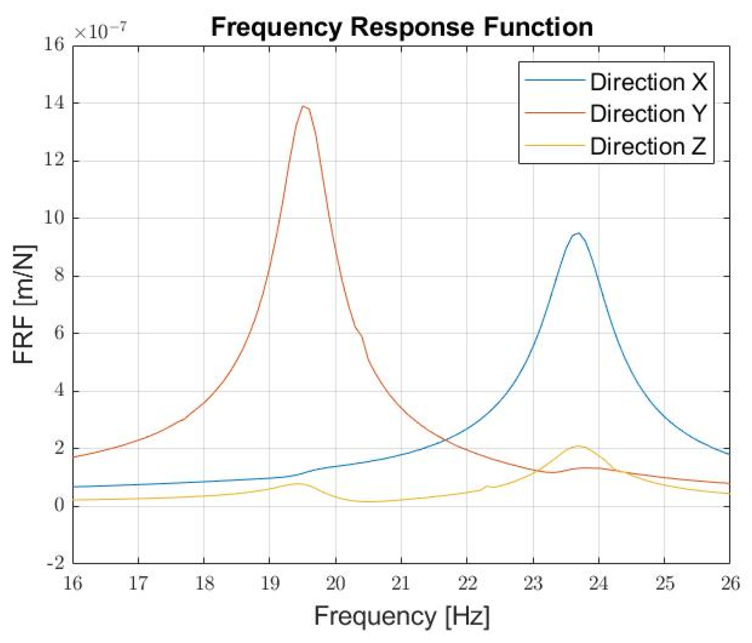
The aim of the frequency response analysis was to identify how the structure responded to sinusoidal excitations in a specific frequency band that can be excited during the machine motion. A unit force was applied along the X and Y directions, and the application point was the concentrated mass connected to the rest of the structure. A point sensor, where the software evaluates the response, was placed on the column top (Figure 7) and used as a comparison parameter for all the analyses. The frequency band, resolution, and damping values used for the analyses are reported in Table 3.
In Figure 14, the response for the directions X, Y, and Z is plotted as a function of the frequency. As it can be appreciated, the maximum of the oscillation amplitude is reached for the first mode, along the Y direction.
3. Tuned Mass Damper (TMD)
The critical points analyzed so far can be summarized as follows.
- Experimental analysis showed the column oscillating along the X and Y directions at 20 Hz when the Z-Carriage and Y-Group were at their stroke ends, and at 24 Hz when they are completely retracted; therefore, the damping device has to be able to provide simultaneous oscillation neutralization along two different directions.
- The numerical model showed some reasonable discrepancies with respect to the experimental results, even though it provided consistent and useful information. Despite these differences, the numerical model was exploited for the dynamic damper tuning, by acting on the most critical frequency, aware of the fact that some differences may be present in practice.
These considerations lead to the dynamic damper design:
- To provide the same stiffness independently of the direction, which leads to the choice of a cylindrically shaped spring.
- To keep the mass ratio as low as possible to secure the Cartesian robot performances.
- To be tuned at a frequency close to 20 Hz, as it was the most dangerous, but with the possibility of changing the frequency slightly, depending on the actual resonant frequency of the machine in operating condition. Therefore, additional masses were considered, to be added in a simple way to the principal one. Being the masses small with respect to the whole structure, no significant variations are induced in the mass ratio.
- To realize a compact design to be assembled on the column top.
The procedure followed in order to design the dynamic damper is hereby reported. It includes how the dynamic damper mass was selected as a function of the mass ratio, how the dynamic damper stiffness was defined as a function of the tuning frequency, and how the geometric parameters of the spring, such as height and surface area, were selected.
- The mass ratio μ, between the dynamic damper mass md and the structure mass Mr, was selected, and the dynamic damper mass was evaluated according to Equation (2). In order to make the initial evaluation easier, an initial mass ratio of 1.55% was selected, valid both for the X direction and the Y direction. The main idea behind this was to avoid too heavy a dynamic damper, but still allow the dynamic damping capabilities and use the same mass along both directions.
- The stiffness of the dynamic damper, kd, was computed by relying on a simple 1-DoF equivalent model as follows.where
- Diameter D, height h, and shear modulus G were selected according to Equation (5). The geometric parameters are related to the dynamic damper spring dimensions, whilst the shear moduli to its material.
- CAD design was carried out.
- FEM modal and frequency response analyses were performed to verify the proposed solution.
It is planned to manufacture the masses in lead and the cylindrical spring in Styrene–Butadiene Rubber (SBR) and the whole structure in steel. These materials were chosen to guarantee higher compactness. An additional consideration on SBR is due, since the commercial components available generally do not display indications about Young (E) nor shear modulus. For this reason, they were evaluated as a function of the Shore A hardness, S, according to the Gent semi-empirical formula [37].
3.1. Single Spring Design
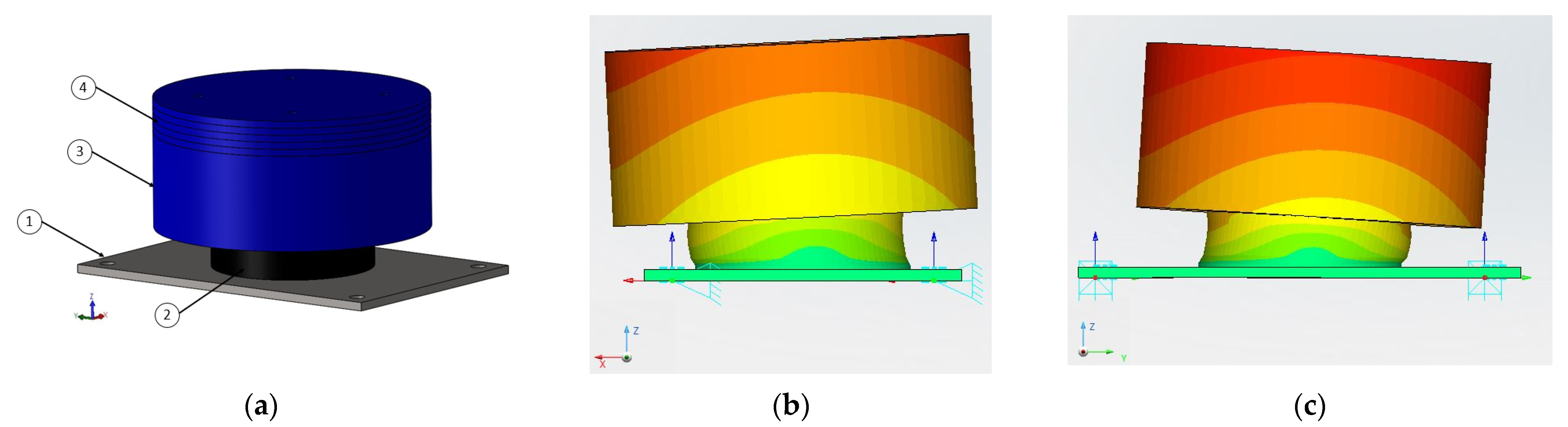
The first design was the dynamic damper depicted in Figure 15a, characterized by the parameters listed in Table 4. As visible from the figure, the design foresees a steel support (1) that creates an interface between the dynamic damper and the machine. The rubber element (2) is glued to the support on the lower surface and to the mass (3) on the upper surface. A circular groove 2 mm deep is made on both the support and the mass to allow a proper gluing of the spring element. The additional disks (4), which can be added or subtracted, allow the tunability of the damper. A modal analysis was run to evaluate if the natural frequency of the equivalent simple 1-DoF model and the numerical one matched. This point was important to verify if the spring element actually worked in shear mode and to ensure a higher control level on the dynamic damper parameters.
Unfortunately, this was not the case, since the results showed relevant differences between the 1-DoF natural frequency and the numerical one, 20.3 Hz against 15.2 Hz, respectively. This difference can be justified by the fact that the mass is characterized by a remarkable height with respect to the spring one, thus inducing a higher center of mass and a consequent imbalance that also produces a rotational movement of the mass, as depicted in Figure 15b,c.
3.2. Parallel Springs Design
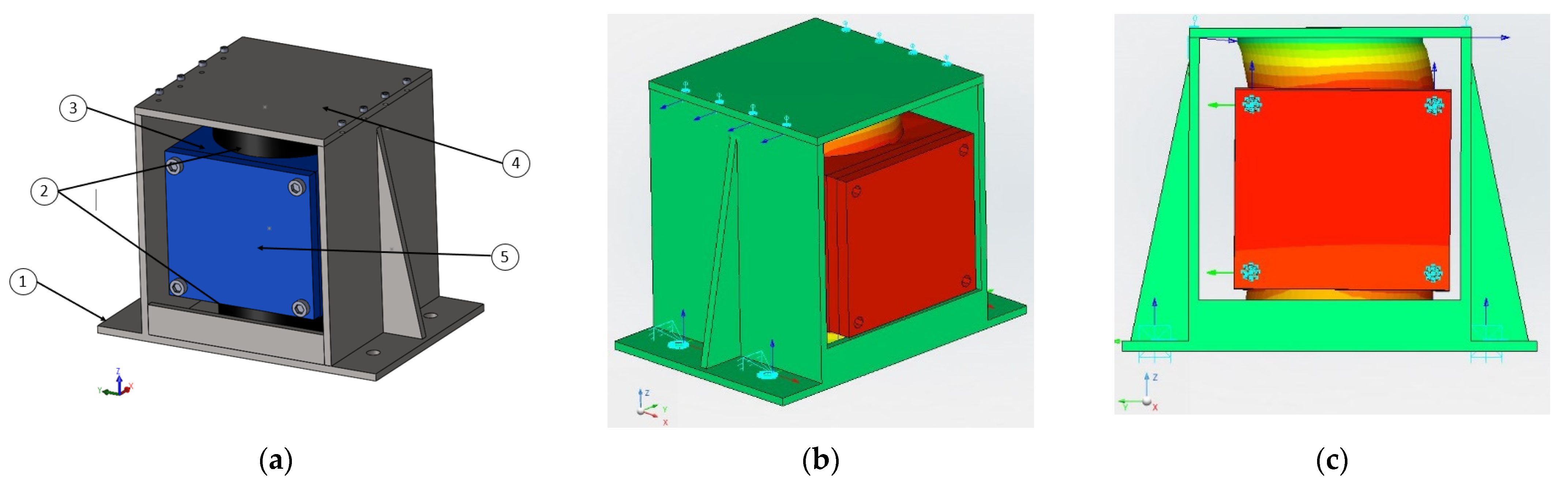
An alternative design is proposed as depicted in Figure 16a. In this case, two parallel and identical springs (2) are used to ensure the dynamic damper works in shear mode.
As can be appreciated from Figure 16a, the design foresees a steel support (1) on which a groove 2 mm deep is machined to allow the proper placing of the cylindrical rubber element (2). The same applies for the top and bottom surfaces of the central mass (3) and the superior cover (4). The two springs are glued to the damper external structure on their top and bottom surfaces. As in the previous design, there is the possibility to add or remove masses (5) in order to tune the dynamic damper. As a first step of the damper design, a modal analysis was performed to verify whether the dynamic damper oscillated at the desired natural frequency. As shown in Figure 16b,c, the first natural frequency resulted to be quite close to the equivalent 1-DoF one. In Table 4, dynamic damper parameters are reported in a comparison with the first design. As can be noticed, a higher correlation between the 1-DoF simplified model and the numerical one can be found in the present design, because this configuration allows the spring element to actually work in shear mode. As a consequence, a higher control on the design is exerted, the damper behaves as expected, and possible modifications may be estimated in a more accurate way just by relying on the simplified model.
3.2.1. TMD Tuning
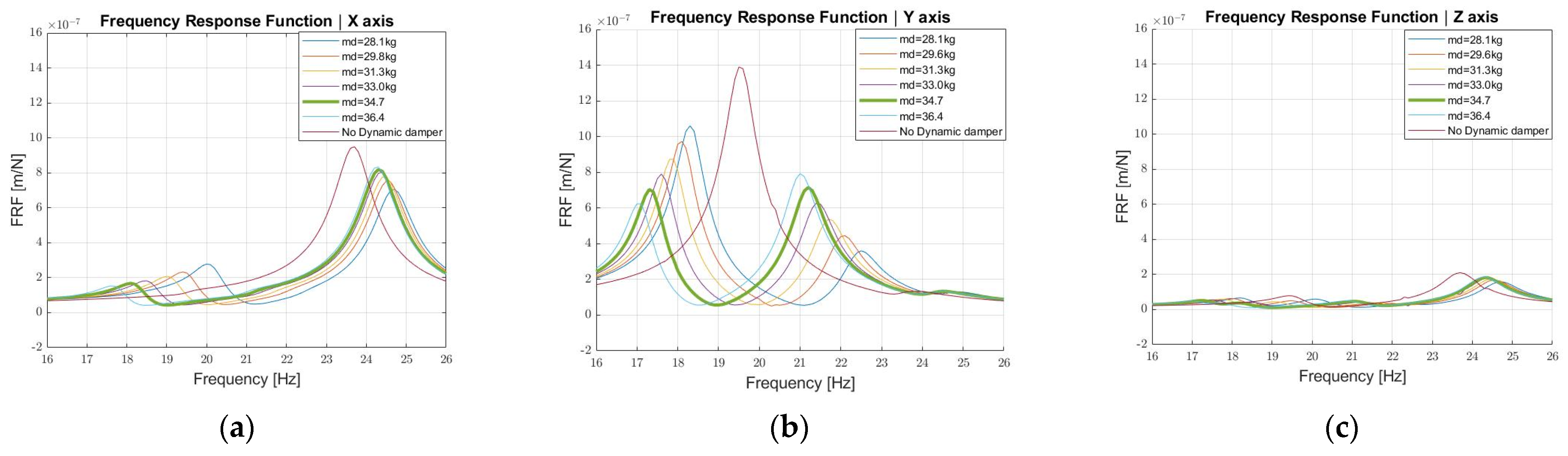
In order to mimic realistic working conditions, frequency response analyses were performed on the machine with the damper on top of it. The decision was to attach the dynamic damper on the column top, as it is the highest oscillation amplitude point; therefore, the dynamic damper is expected to exert the maximum beneficial effect in that position. Furthermore, a damper tuning was realized by adding or subtracting small masses, 1.7 kg each, with the aim of minimizing the maximum oscillation amplitude. The analyses were still carried out according to Table 3 and referred to the same model presented in Figure 7. In Figure 17, the Frequency Response Functions (FRFs) as a function of the dynamic damper mass are reported for each direction. From the analysis of Figure 17, the following observations can be drawn:
- With a mass of 34.7 kg (green thick curve), the FRF maximum along the Y direction can be reduced by 50%, even though two peaks are present, as expected. It must also be highlighted that in this numerical calculation the additional damping of the rubber element was not considered; therefore, a higher reduction may be expected from a practical point of view.
- The dynamic damper is less effective in the X axis since the maximum amplitude reduction is 20%.
Figure 17.
Dynamic damper FRF as a function of the mass along directions X (a), Y (b), and Z (c).

3.2.2. Stiffness Distribution Analysis
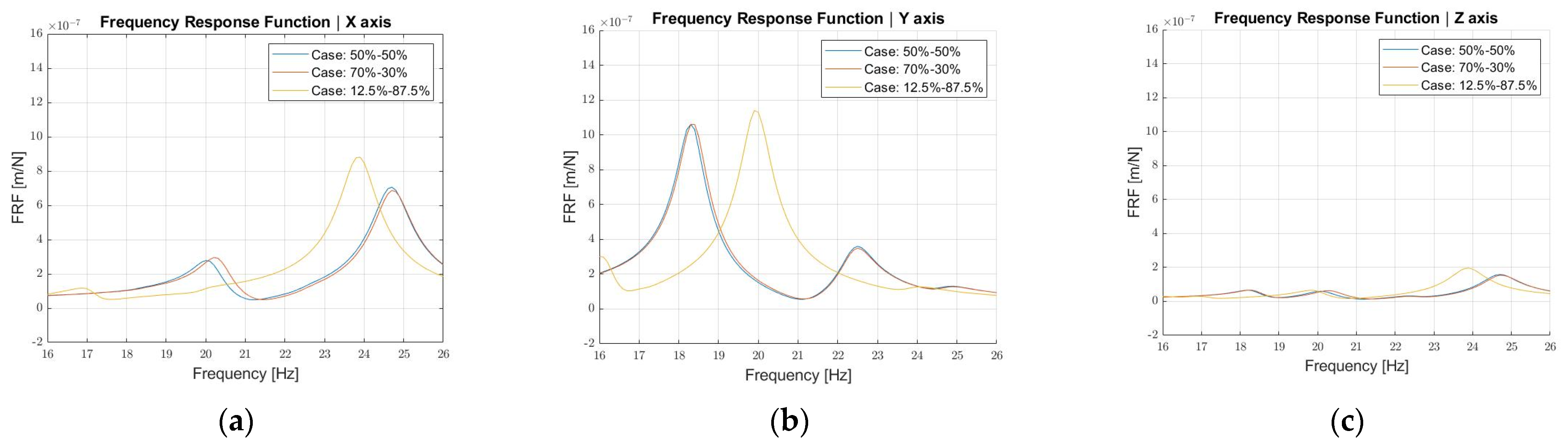
As a last design step, frequency response analyses were run to understand if a different stiffness distribution of the two springs, by keeping the equivalent one constant as well as the mass, would have allowed a reduction of the maximum amplitude. For this reason, a not optimally tuned damper was voluntarily used as the starting condition (case 50–50%). The different stiffness distribution was obtained by using different geometries for the upper and lower springs. As shown in Figure 18, no significant differences are present between the first two designs (case 50–50% and 70–30%) in the forced response. The situation is different for the third case (12.5–87.5%) for which the dynamic damper presents a lower natural frequency that changes the response of the system. The reason is that the springs do not work in shear mode.
3.2.3. Damping Estimation
All the analyses performed so far do not take into account the internal damping effect provided by the dynamic damper. As previously stated, it is planned to manufacture the springs in an elastomeric material, Styrene–Butadiene Rubber (SBR) to be precise; therefore, a viscoelastic behavior is to be expected. More generally, viscoelastic materials display both viscous and elastic properties when undergoing deformations, thus implying a dependency of their properties on time. When undergoing harmonic stress cycles, they exhibit a hysteresis cycle, since the strain ε lags the stress σ by a certain angle ϕ. For the case being, it is assumed the deformations are small enough to consider a linear viscoelastic response of the material. The stress–strain relation can be then written according to Equation (8).
The Young modulus E*, expressed by the ratio between the strain and the stress, is a complex quantity, that can be written according to Equations (9) and (10).
in which the real part E′ is defined as the storage modulus and provides the elastic behavior of the material, whilst the imaginary part E″ is defined as the loss modulus and provides the damping behavior of the material. Their ratio η can be expressed according to Equation (11) and corresponds to the loss factor of the material.
Equivalently, the same considerations can be expressed to the stiffness of a structural component, thus obtaining, as per Equations (12) and (13)
From a practical point of view, in order to implement these considerations on the FE model and perform the frequency response analysis, an equivalent viscous damping was computed according to Equation (14).
where:
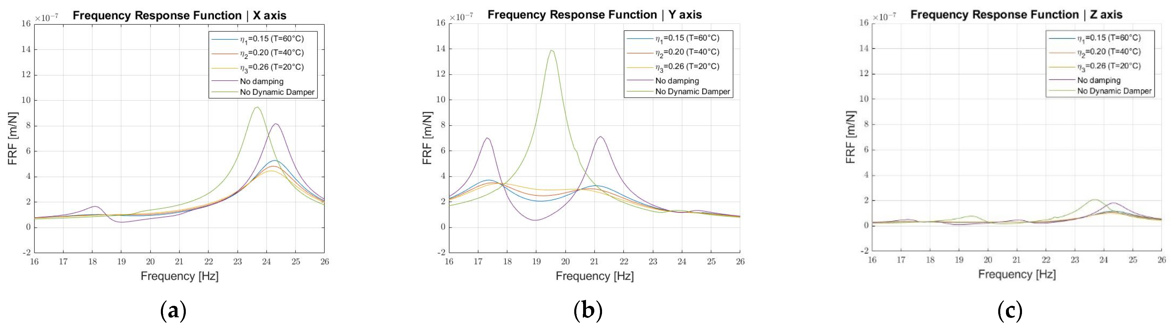
The styrene–butadiene rubber mechanical and dynamic properties are influenced by the working temperature, as indicated in [38]; therefore, frequency response analyses were run to evaluate:
- How much the robot response was affected by the damping effect of the elastomeric material.
- How the robot response may vary as a function of the working temperature, considering that the loss factor shows a linear dependence on the temperature for the considered range of 20–60 °C.
In Figure 19, the results of these analyses are reported, compared to the cases in which damping is neglected (no damping) and no dynamic damper is assembled on the structure.
In an ideal case, the machine would be working at a temperature around 20 °C, but due to the heat generated during the cutting process for the specific application, the external temperature may reach values up to 40 °C in the cutting chamber. An additional analysis was performed assuming the energy dissipated by the damper may induce the elastomeric material temperature increase up to 60 °C. This is a strong assumption, but conservative from the damping effect point of view, since the material loss factor is inversely proportional to the temperature variation. It can be noticed that relevant temperature variations do not significantly affect the response of the system, thus guaranteeing a maximum amplitude reduction to a great extent anyway. As can be appreciated from Figure 19, the damping estimation leads to favorable outcomes, in the sense that the maximum of the response results is highly reduced. In the best case scenario (T = 20 °C and η = 0.26), along the Y axis, an additional reduction of 50.9% can be reached with respect to the undamped case, thus providing an overall maximum amplitude reduction of 75.1% with respect to the case without dynamic damper. The same considerations hold for the X direction as well, where an overall reduction of 53.1% can be reached.
3.2.4. Criticalities Evaluation
Once the design was assessed, possible criticalities that might be present after the machining and assembly of the different components were investigated. In detail, the following variations with respect to the ideal case were analyzed:
- Uncertainties of the Young and consequently of the shear moduli.
- Imperfect gluing of the components.
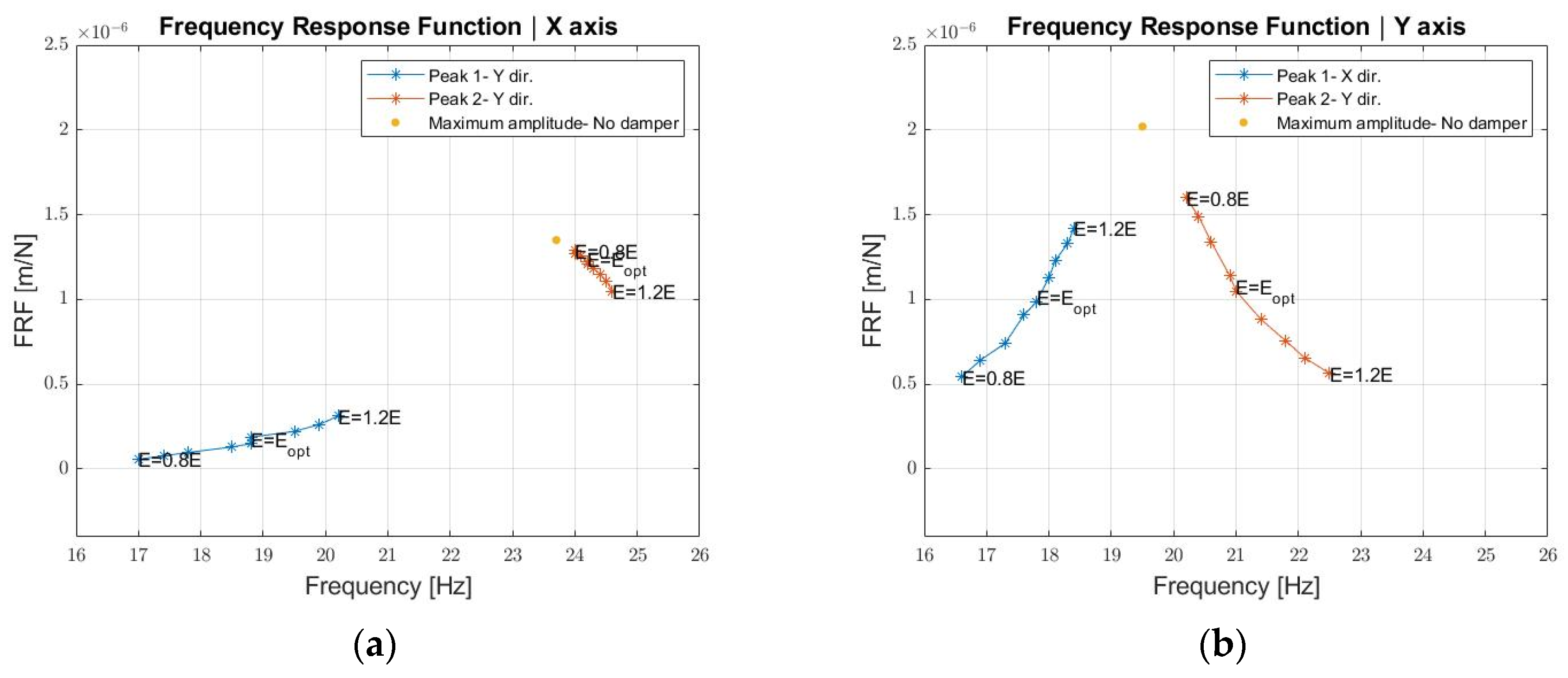
Starting from the optimal configuration of the dynamic damper and neglecting the hysteretic damping effect, an uncertainty up to ±20% on the Young modulus was analyzed. In Figure 20, the values of the amplitude of the first two peaks of the FRF and the corresponding frequencies are plotted as the elastic modulus changes in both the X and Y directions. The following observations can be drawn:
- If the Young modulus decreases, the first peak amplitude decreases as well as its frequency, on the contrary, the second peak increases in amplitude and decreases in frequency along both the X and Y directions. As a result, the FRF shifts left. Overall, a 20% reduction of the Young modulus still guarantees the TMD effectiveness, but to a reduced extent, as the FRF maximum decreases by 21% along the X axis and 4% along the Y axis with respect to the case without dynamic damper.
- If the Young modulus increases, the first peak increases both in amplitude and frequency, whilst the second peak decreases in amplitude and increases in frequency along both the X and Y directions. A frequency increase happens in this case for the two peaks of the FRF. A 20% increase in the Young modulus guarantees the TMD effectiveness, but the FRF maximum decreases by 30% along the X direction and 22% along the Y direction with respect to the case without the dynamic damper. From a design point of view, if uncertainties on the material elastic modulus are high, it would be then beneficial to select a stiffer material and perform the tuning of the damper by adding more masses.
Figure 20.
Dynamic damper FRF as a function of the Young modulus along directions X (a) and Y (b).

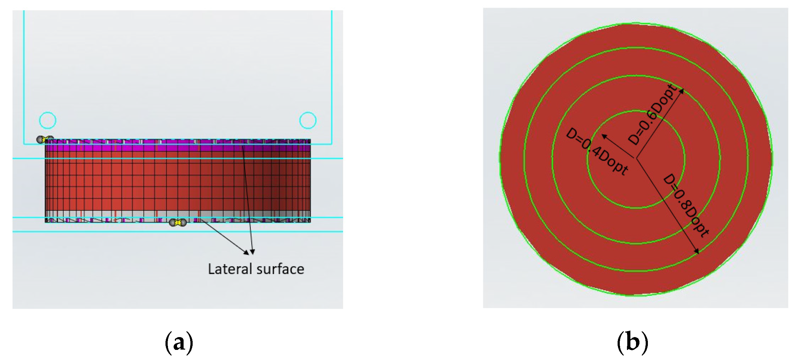
Another source of uncertainty might be the gluing of the surfaces, which may turn out to be not perfectly uniform. This uncertainty was simulated by assuming different extensions of the glued areas. The dynamic analyses were then performed for different “glued contact surfaces”, each one characterized by a certain diameter, as shown in Figure 21.
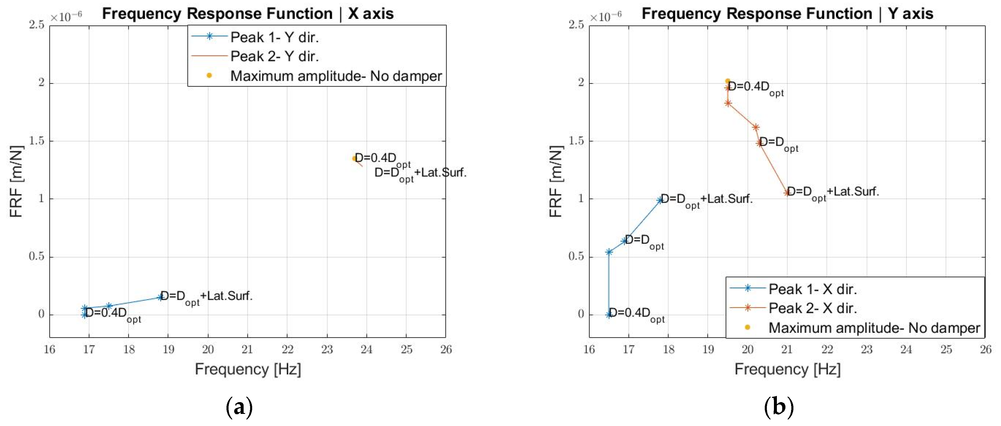
In Figure 22, the values of the first two peaks of the FRF and the corresponding frequencies are plotted as the diameter of the glued surface changes in both the X and Y directions. It can be noticed that the model shows a high sensitivity to the glue contact. Between the complete gluing (100% of the diameter and lateral surface) and the 80% of the diameter a remarkable decrease of the 1st peak amplitude, an increase in the 2nd peak amplitude and frequency shift towards the right happens, consistently to what was already observed in the Young modulus reduction. This is because when an adequate constraint is not provided to the spring element, the rubber material is not completely involved in supporting the mass along the shear deformation. This leads to a strong decrease in the overall stiffness. In the limit condition (40% of the diameter), the dynamic damper has no effect. This means that particular attention will have to be paid to the choice of glue and to properly carry out the gluing of the components.
4. Conclusions
For a high-precision robot involved in metal sheet cutting, it is crucial to guarantee the required dimensional and geometrical tolerances when performing the cutting operation. Since the above-mentioned robot is already in the development phase, the objective becomes even more complicated when a solution must be found in order not to increase the time-to-market or project cost of the machine. In this scenario, it is here proposed to use a dynamic damper to shift the machine frequencies that most disturb the cutting phase and to limit the amplitudes of vibrations. The proposed dynamic damper provides a fast and low-cost solution because it avoids a relevant re-design of the main components, necessary to guarantee a higher structural rigidity. It also avoids dismounting and re-assembling operations, which require time. Four fixing holes are the requirement to allow the dynamic damper to work as it should. Furthermore, the utilization of two cylindrically shaped springs, working in shear mode in a parallel arrangement, determines a higher degree of compactness and simplicity, since the stiffness is independent of the angular coordinate and able to reduce vibration amplitudes along two orthogonal directions at the same time. On top of that, the proposed design guarantees a certain grade of tunability before operation, by means of small masses addition or subtraction. From a numerical standpoint, there exists an optimal mass value, and consequent optimal frequency ratio, that leads to the maximum response amplitude minimization, obtaining a reduction equal to 75% when material hysteretic damping is considered as well. On the other hand, possible problems may arise from the manufacturing point of view. As shown, a 20% negative deviation of the Young modulus induces an oscillation amplitude decrease of just 21%, thus making it convenient to use stiffer material, if uncertainties are high, and then tune the damper by using a different mass. The uncertainty in the extension of the glued surfaces of the damper components results to be the most critical aspect, leading to no damping effect in the worst-case scenario due to an overall stiffness reduction. In conclusion, the proposed damper design proved to be effective on a numerical basis. Manufacturing and experimental testing on the robot prototype will be the following steps of the present research.
Author Contributions
Conceptualization, S.D., T.M.B., C.G. and P.S.; methodology, S.D., T.M.B., C.G. and P.S.; software, S.D.; writing—original draft preparation, S.D.; writing—review and editing, T.M.B. and C.G.; supervision, T.M.B., C.G. and P.S.; funding acquisition, P.S. All authors have read and agreed to the published version of the manuscript.
Funding
This research was funded by EFORT-EUROPE s.r.l., name of Ph.D. scholarship: Dynamic Design of a high-speed robot.
Institutional Review Board Statement
Not applicable.
Informed Consent Statement
Not applicable.
Data Availability Statement
Not applicable.
Conflicts of Interest
The authors declare no conflict of interest.
References
- Brennan, M.J.; Ferguson, N.S. Vibration control. In Advanced Applications in Acoustics, Noise and Vibration, 1st ed.; Fahy, F., Walker, J., Eds.; Spoon Press: New York, NY, USA, 2004; Volume 4. [Google Scholar]
- Nad, M. Structural dynamic modification of vibrating systems. J. Appl. Comput. Mech. 2007, 1, 203–214. [Google Scholar]
- Neubauer, M.; Schwaericke, F.; Radmann, V.; Sarradj, E.; Modler, N.; Dannemann, M. Material Selection Process for Acoustic and Vibration Applications Using the Example of a Plate Resonator. Materials 2022, 15, 2935. [Google Scholar] [CrossRef] [PubMed]
- Karnopp, D. Active and semi-active vibration isolation. In Proceedings of the Sixth Cairo University International MDP Conference, Cairo, Egypt, 2–4 January 1996. [Google Scholar] [CrossRef]
- Baz, A.M. Active and Passive Vibration Damping, 1st ed.; John Wiley & Sons Inc: New York, NY, USA, 2019. [Google Scholar]
- Ashock, B.; Jeevanantham, A.K.; Vignesh, R.; Bhat Hire, K.R.; Prabhu, K.; Raaj Kumar, R.A.; Shivshankar, N.; Sudhagar, P.E. Calibration of engine parameters and fuel blend for vibration and noise characteristics in CRDI engine fuelled with low viscous biofuel. Fuel 2021, 288, 203–214. [Google Scholar] [CrossRef]
- Nguyen, V.; Johnson, J.; Melkote, S. Active vibration suppression in robotic milling using optimal control. Int. J. Mach. Tools Manuf. 2020, 152, 103541. [Google Scholar] [CrossRef]
- Pelàez, G.; Pelaez, G.; Perez, J.M.; Vizàan, A.; Bautista, E. Input shaping reference commands for trajectory following Cartesian machines. J. Control. Eng. Pract. 2005, 13, 941–958. [Google Scholar] [CrossRef]
- Kasprowiak, M.; Parus, A.; Hoffmann, M. Vibration Suppression with Use of Input Shaping Control in Machining. Sensors 2022, 22, 2186. [Google Scholar] [CrossRef]
- De Luca, A.; Book, W.J. Robots with Flexible Elements. In Springer Handbook of Robotics, 1st ed.; Siciliano, B., Khatib, O., Eds.; Springer Nature: Cham, Switzerland, 2016. [Google Scholar]
- Ramesh, R.; Mannan, M.A.; Poo, A.N. Error compensation in machine tools—A review. Part I: Geometric, cutting-force induced and fixture-dependent errors. J. Mach. Tools Manuf. 2000, 40, 1235–1256. [Google Scholar] [CrossRef]
- Gao, H.; Sun, J.; Chen, W.; Zhang, Y.; Wu, Q. Structural bionic design for a machine tool column based on leaf veins. J. Mech. Eng. Sci. 2017, 232, 2764–2773. [Google Scholar] [CrossRef]
- Yan, S.; Li, B.; Hong, J. Bionic design and verification of high-precision machine tool structures. J. Adv. Manuf. Technol. 2015, 81, 73–85. [Google Scholar] [CrossRef]
- Li, B.; Hong, J.; Liu, Z. Stiffness design of machine tool structures by a biologically inspired topology optimization method. J. Mach. Tools Manuf. 2014, 84, 33–44. [Google Scholar] [CrossRef]
- Zamora-Garcia, D.A.; Ramirez-Reivich, A.C.; Corono-Lira, M.P. On the Use of Tuned Mass Dampers for Reducing the Nonlinear Vibrations of Planar Parallel Cable Robots. Int. J. Mech. Eng. Robot. Res. 2019, 8, 406–412. [Google Scholar] [CrossRef]
- Bahrami, M.R.; Abed, S.A. Mechanics of robot inspector on electrical transmission lines conductors: Performance analysis of dynamic vibration absorber. J. Vibroeng. 2019, 25, 60–64. [Google Scholar] [CrossRef]
- Mrad, C.; Okabe, S.; Kamiya, Y.; Seki, H. Vibration Control of Mobile Robot Vehicle by Dynamic Vibration Absorber. JSME Int. J. 1999, 42, 62–70. [Google Scholar] [CrossRef]
- Bian, Y.; Liang, X.; Gao, Z. Vibration Reduction for a Flexible Arm Using Magnetorehological Elastomer Vibration Absorber. J. Shock. Vib. 2018, 2018, 9723538. [Google Scholar] [CrossRef]
- Yuan, H.; Wan, M.; Yang, Y. Design of tunable mass damper for mitigating vibrations in milling of cylindrical parts. Chin. J. Aeronaut. 2019, 32, 748–758. [Google Scholar] [CrossRef]
- Yang, Y.; Dai, W.; Liu, Q. Design and implementation of two-degree-of-freedom tuned mass damper in milling vibration mitigation. J. Sound Vib. 2015, 335, 78–88. [Google Scholar] [CrossRef]
- Ma, W.; Yu, J.; Yang, Y.; Wang, Y. Optimization and Tuning of Passive Tuned Mass Damper Embedded in Milling Tool for Chatter Mitigation. J. Manuf. Mater. Prop. 2020, 5, 2. [Google Scholar] [CrossRef]
- Lee, J.; Kim, C.J.; Lee, C.; Oh, C. Optimal Design of Multiple Tuned Mass Dampers to Reduce Vibrations of a Ram-Type Structure with Varying Dynamics via a Control Theoretic Framework. J. Manuf. Sci. Eng. 2020, 142, 021009. [Google Scholar] [CrossRef]
- Genta, G. Vibration Dynamics and Control, 1st ed.; Springer Nature: Cham, Switzerland, 2009. [Google Scholar] [CrossRef]
- Frahm, H. Device for Damping Vibrations of Bodies. US Patent No: 989,958, 18 April 1911. [Google Scholar]
- Den Hartog, J.P. Mechanical Vibrations, 1st ed.; McGraw-Hill: New York, NY, USA, 1956. [Google Scholar]
- Rana, R.; Soong, T.T. Parametric study and simplified design of tuned mass dampers. J. Eng. Struct. 1997, 20, 193–204. [Google Scholar] [CrossRef]
- Warburton, G.B. Optimum abrosber parameters for various combinations of response and excitation parameters. J. Earthq. Eng. Struct. Dyn. 1982, 10, 381–401. [Google Scholar] [CrossRef]
- Marano, G.C.; Greco, R.; Chiaia, B. A comparison between different optimization criteria for tuned mass dampers design. J. Sound Vib. 2010, 329, 4880–4890. [Google Scholar] [CrossRef]
- Leung, A.Y.T.; Zhang, H. Particle swarm optimization of tuned mass dampers. J. Eng. Struct. 2009, 31, 715–728. [Google Scholar] [CrossRef]
- Ahsan, R.; Rana, S.; Ghani, S.N. Cost Optimum Design of Posttensioned I-Girder Bridge Using Global Optimization Algorithm. J. Struct. Eng. 2012, 138, 273–284. [Google Scholar] [CrossRef]
- Javidialesaadi, A.; Wierschem, N.E. Design and performance evaluation of inerter-based tuned mass dampers for a ground acceleration excited structure. Soil Dyn. Earthq. Eng. 2021, 140, 106463. [Google Scholar] [CrossRef]
- Desu, N.B.; Deb, S.K.; Dutta, A. Coupled tuned mass dampers for control of coupled vibrations in asymmetric buildings. J. Struct. Control Health Monit. 2006, 13, 897–916. [Google Scholar] [CrossRef]
- Li, Y.; Li, J.; Du, H. A state-of-the-art review on magnetorheological elastomer devices. J. Smart Mater. Struct. 2006, 15, 897–916. [Google Scholar] [CrossRef]
- Deng, H.; Gong, X.; Wang, L. Development of an adaptive tuned vibration absorber with magnetorheological elastomer. J. Smart Mater. Struct. 2006, 15, N111–N116. [Google Scholar] [CrossRef]
- Plesseira, J.P.; Rochus, P.; Defise, J.M. Effective modal masses. In Proceedings of the 5th Congrés National de Méecanique Théorique et Appliquée, Louvain-la-neuve, Belgium, 23–24 May 2000. [Google Scholar]
- Ahmad, M.S.; Jamil, M.; Iqbal, J.; Khan, M.N.; Malik, M.H.; Butt, S.I. Modal Analysis of Ship’s Mast Structure using Effective Mass Participation Factor. Indian J. Sci. Technol. 2016, 9, 1–5. [Google Scholar] [CrossRef]
- Geant, A.N. On the relation between indentation hardness and Young’s modulus. J. Rubber Chem. Technol. 1958, 31, 896–906. [Google Scholar] [CrossRef]
- Nazirah, A. A methodology for Developing High Damping Materials with Applications to Noise Reduction of Railway Track. Ph.D. Thesis, University of Southampton, Southampton, UK, February 2009. [Google Scholar]
Figure 1.
Cartesian robot prototype.

Figure 2.
Cut sample.

Figure 3.
Accelerometer application points.

Figure 4.
Displacement measurements in the frequency domain as a function of the X axis movement along direction X (a), Y (b), and Z (c).
Figure 4.
Displacement measurements in the frequency domain as a function of the X axis movement along direction X (a), Y (b), and Z (c).

Figure 5.
Displacement measurements in the frequency domain as a function of the Y axis movement along direction X (a), Y (b), and Z (c).
Figure 5.
Displacement measurements in the frequency domain as a function of the Y axis movement along direction X (a), Y (b), and Z (c).

Figure 6.
Displacement measurements in the frequency domain as a function of the Z axis movement along direction X (a), Y (b), and Z (c).
Figure 6.
Displacement measurements in the frequency domain as a function of the Z axis movement along direction X (a), Y (b), and Z (c).

Figure 7.
Meshed model.

Figure 8.
Extreme positions characterizing Mode 1—19.5 Hz.

Figure 9.
Extreme positions characterizing Mode 2—23.7 Hz.

Figure 10.
Extreme positions characterizing Mode 5—50.6 Hz.

Figure 11.
Extreme positions characterizing Mode 6—53.0 Hz.

Figure 12.
Extreme positions characterizing Mode 7—68.1 Hz.

Figure 13.
Extreme positions characterizing Mode 8—75.4 Hz.

Figure 14.
Robot Frequency Response Function.

Figure 15.
Dynamic damper, single spring CAD design (a), and mode shapes at 15.2 Hz (b,c).

Figure 16.
Dynamic damper, single spring CAD design (a), and mode shapes at 19.0 Hz (b,c).

Figure 18.
Dynamic damper FRF as a function of the stiffness distribution along directions X (a), Y (b), and Z (c).
Figure 18.
Dynamic damper FRF as a function of the stiffness distribution along directions X (a), Y (b), and Z (c).

Figure 19.
Dynamic damper FRF as a function of the loss factor along directions X (a), Y (b), and Z (c).
Figure 19.
Dynamic damper FRF as a function of the loss factor along directions X (a), Y (b), and Z (c).

Figure 21.
Glued contact surface and diameter: front view (a) and top view (b).

Figure 22.
Dynamic damper FRF as a function of the gluing diameter along directions X (a) and Y (b).
Figure 22.
Dynamic damper FRF as a function of the gluing diameter along directions X (a) and Y (b).


Table 1.
Dynamic and kinematic parameters as a function of the motor axis.
| Direction | Moving Mass (kg) | Nominal Force (N) | Peak Force (N) | Acceleration (m/s2) | Speed (m/s) | Stroke (mm) |
|---|---|---|---|---|---|---|
| X | 2026 | 10,000 | 20,000 | 10 | 5 | 2400 |
| Y | 360 | 2500 | 4700 | 10 | 4 | 1270 |
| Z | 569 | 6000 | 12,000 | 10 | 2 | 325 |
Table 2.
Effective Mass Fractions (EMFs).
| Mode | Frequency (Hz) | EMF X Direction (-) | EMF Y Direction (-) | EMF Z Direction (-) |
|---|---|---|---|---|
| 1 | 19.5 | 7.3 × 10⁻⁴ | 4.1 × 10⁻¹ | 4.2 × 10⁻³ |
| 2 | 23.7 | 3.7 × 10⁻¹ | 6.0 × 10⁻⁵ | 3.5 × 10⁻² |
| 3 | 43.4 | 5.9 × 10⁻⁴ | 1.0 × 10⁻³ | 8.2 × 10⁻⁴ |
| 4 | 47.6 | 4.6 × 10⁻³ | 3.5 × 10⁻⁴ | 3.6 × 10⁻³ |
| 5 | 50.6 | 1.1 × 10⁻² | 1.3 × 10⁻¹ | 1.3 × 10⁻¹ |
| 6 | 53.0 | 2.0 × 10⁻¹ | 2.1 × 10⁻³ | 1.8 × 10⁻¹ |
| 7 | 68.1 | 4.6 × 10⁻² | 2.9 × 10⁻¹ | 1.1 × 10⁻¹ |
| 8 | 75.4 | 3.6 × 10⁻¹ | 1.2 × 10⁻² | 1.3 × 10⁻¹ |
| 9 | 80.1 | 2.8 × 10⁻⁵ | 7.7 × 10⁻² | 2.2 × 10⁻¹ |
| 10 | 90.6 | 7.6 × 10⁻⁵ | 5.8 × 10⁻² | 3.0 × 10⁻³ |
Table 3.
Frequency response analysis setting parameters.
| Quantity | Value |
|---|---|
| Frequency band (Hz) | 16–26 |
| Frequency resolution (Hz) | 0.1 |
| Fx (N) | 1 |
| Fy (N) | 1 |
| Critical damping fraction (-) | 0.02 |
Table 4.
Dynamic damper parameters, single spring, and parallel springs design.
| Quantity | Single Spring Design | Parallel Springs Design |
|---|---|---|
| fd,1-DoF (Hz) | 20.3 | 20.1 |
| fd,Num (Hz) | 15.2 | 19.0 |
| md (kg) | 29.5 | 29.6 |
| Bm (mm) | 195 | 130 |
| Wm (mm) | - | 170 |
| Hm (mm) | 93 | 121 |
| kd,tot (kN/m) | 478.9 | 472.9 |
| Dk (mm) | 115 | 115 |
| Hk (mm) | 32 | 32 |
| Gk (MPa) | 1.5 | 0.8 |
| S (Shore A) | 65 | 50 |
Publisher’s Note: MDPI stays neutral with regard to jurisdictional claims in published maps and institutional affiliations. |
© 2022 by the authors. Licensee MDPI, Basel, Switzerland. This article is an open access article distributed under the terms and conditions of the Creative Commons Attribution (CC BY) license (https://creativecommons.org/licenses/by/4.0/).
Share and Cite
MDPI and ACS Style
D’Imperio, S.; Berruti, T.M.; Gastaldi, C.; Soccio, P. Tunable Vibration Absorber Design for a High-Precision Cartesian Robot. Robotics 2022, 11, 103. https://doi.org/10.3390/robotics11050103
AMA Style
D’Imperio S, Berruti TM, Gastaldi C, Soccio P. Tunable Vibration Absorber Design for a High-Precision Cartesian Robot. Robotics. 2022; 11(5):103. https://doi.org/10.3390/robotics11050103
Chicago/Turabian StyleD’Imperio, Simone, Teresa Maria Berruti, Chiara Gastaldi, and Pietro Soccio. 2022. "Tunable Vibration Absorber Design for a High-Precision Cartesian Robot" Robotics 11, no. 5: 103. https://doi.org/10.3390/robotics11050103
Note that from the first issue of 2016, this journal uses article numbers instead of page numbers. See further details here.