A Rotor-Sync Signal-Based Control System of a Doubly-Fed Induction Generator in the Shaft Generation of a Ship


Faculty of Energy Engineering, Thuyloi University, 175 Tay Son, Dong Da, Hanoi 11398, Vietnam
Processes 2019, 7(4), 188; https://doi.org/10.3390/pr7040188
Submission received: 20 February 2019
/
Revised: 28 March 2019
/
Accepted: 29 March 2019
/
Published: 1 April 2019
(This article belongs to the Special Issue Advances in Theoretical and Computational Energy Optimization Processes)
Abstract
:A doubly-fed induction machine in generator-mode is popularly used for energy generation, particularly in the case of a variable speed, such as in the wind generator, the shaft generator of a ship, because the doubly-fed induction generator is able to maintain a stable frequency when changing the rotor speed. This paper aims to propose a novel method for controlling the shaft generation system of a ship using a doubly-fed induction generator. This method uses the rotor signals of a small doubly-fed induction machine as base components to create the control signal for the doubly-fed induction generators. The proposed method will be proven by both theory and a simulation model. The advantage of the proposed method is that the control system of the generator can be simply built, but it functions effectively. The generator voltage always coincides with the grid voltage, even when the grid voltage and the rotor speed are changed, and the reactive and active power of the generator fed into the grid can be separately controlled.
1. Introduction
Today, fuel resources are increasingly becoming exhausted, so identifying and using renewable sources is very urgent and necessary. In order for these renewable energy sources to operate reliably, they must be able to operate together or connected to the grid. Some researches [1,2] have succeeded in solving these difficulties. However, on a ship, it is more difficult to connect the generator voltage to the grid, because the grid of the ship is a soft-grid, and so the voltage is frequently changed. Therefore, solving this problem is a challenge and an opportunity for scientists.
On a ship, the power station must be optimally exploited when cruising to reduce energy consumption, noise, environmental pollution and to avoid the negative impact on people and nature. When navigating on the sea, in steady climatic and weather conditions, the main propulsion engines of the ship’s propeller often do not reach full capacity. To take advantage of this surplus capacity, the ship is designed with a shaft generator, which works together with the diesel generator.
The required power for a ship in cruise mode only accounts for 5–10% of the main engine power. Therefore, ships with a shaft generator use the main engine’s surplus power to save the operation time of the diesel generators, reduce the consumption of materials, and improve the lifetime of the diesel generator. In particular, the production cost of a power unit, created by a shaft generator, is only equal to 50% of the cost, when using the diesel generator [3].
However, as the power station system adds the shaft generator, the ship’s power system becomes more complicated, posing technical problems that need to be addressed. The most complicated problem is that the output voltage of the shaft generator must coincide with the unstable grid voltage of the ship, when changing the rotor speed of the main engine [4,5]. Further, the engine power is much larger than the electric power, so the rotor speed of the generator is independent of the electric power. The rotor speed depends only on the operation of the ship, so the speed range of the rotor is very wide. Therefore, the most effective solution is to use the doubly-fed induction machine in generator mode because of its ability to maintain a stable frequency of this system.
The doubly-fed induction machine (DFIM) is an induction machine with both stator and rotor windings [6]. The doubly-fed induction machine plays the role of generation (DFIG), with inherent advantages, such as a small control circuit, suitable for the variable speed system, so DFIG has been applied in many energy generation systems, such as the shaft generator in a ship, the wind generator system. In these generator systems, the control circuit is located in the rotor, and the energy emitted in the stator is transmitted to the grid directly. Thus, the control circuit power is much lower than the grid-transmitted power.
The control circuit has two main parts: The first part is connected to the grid [7,8], used to regulate the DC voltage [9,10]. The second part is connected to the rotor of DFIG [11,12], used to control the reactive and active power of DFIG fed into the grid [13,14]. The rotor side control is more complicated than the grid side control, thus attracting many scientists around the globe. In this study, we are only interested in controlling the rotor side control, so we assume that the DC source already exists and is stable.
There is a lot of research on controlling the control system for the rotor side [15,16], most of which use the space vector modulation technique. Relying on that technique, in order for the controller to perform the mission, all parameters of the stator and rotor must be transformed in a synchronous reference frame [17,18], which coincides with the space vector of the grid voltage (grid voltage-orientated coordinates) or with the space vector of the stator flux (stator-flux-orientated coordinates). However, the final parameters for controlling the system are not within these coordinates. Thus, the control structure must consist of two coordinate conversion stages: First, all input and feedback parameters of the controller are transformed in a synchronous reference frame; and lastly, all output parameters of the controller are transformed in the rotor or stator frame. For these reasons, the control system calculations must be more complex.
In this research, the author proposes a simple and effective technique, which does not need the coordinate-conversion stages. Relying on this proposed technique, all signals of the control system are continuous. This technique uses the rotor signals of a small DFIM as a base to create the control signals of the DFIG rotor current.
2. The Proposed Model
The purpose of the control system is to make the DFIG stator voltage coincide with the grid voltage in the case of a changing rotor speed and grid voltage. Thus, the author proposes a method of using a small DFIM with the stator connected to the grid, so the change of the DFIM rotor voltage depends on two factors: the rotor speed and the grid voltage. The natural change in the DFIM rotor voltage is therefore suitable for controlling the DFIG rotor current. DFIM only acts as a sync signal generator, so it has a small capacity. In order for the sync signal to not be distorted, the output of this signal is connected to high resistance. The initially proposed model is shown in Figure 1.
The generation system includes:
- The main machine, which is used for pulling the propeller. In addition, it is also used for pulling the shaft generator through the gearbox.
- DFIM with the stator connected to the grid and the rotor connected to the high-resistance mode. The DFIM rotor signal is a base component for creating the control signals for DFIG.
- An isolation stage, which is a circuit that has a high-resistance input, so the DFIM rotor is connected to the high resistance.
- The current control circuit, which creates the output current value that is equal to the input voltage value.
- DFIG, which creates the power that is fed into the grid.
Rotors of DFIG and DFIM are connected to each other tightly so that the angles between the stator and rotor are equal.
3. Building the Equations of the Proposed Model
3.1. The Initial Equations
The system includes two machines, so the parameter symbols are as follows: GX for DFIG, and MX for DFIM. For example, is the stator resistance of DFIG, and is the stator resistance of DFIM.
The DFIM rotor is connected to the high resistance, so . Substituting for (1c), the DFIM stator flux . Substituting for (1a), the DFIM stator voltage:
On the rotor shaft-orientated coordinates, the DFIM rotor voltage and DFIM rotor flux equations are as follows [20,21]:
Substituting for (3b), , and substituting for (3a):
is fed into the isolation stage. The first section of the isolation stage is the amplifier with the gain Gss, so the output voltage vector of this section in the rotor shaft-orientated coordinate is:
Next, is fed into the integral section, so the signal output vector of the integral section in the rotor shaft-orientated coordinate is:
Converting (6) into an equation in the grid voltage-orientated coordinates:
is fed into the current control circuit. This circuit makes the output current value equal the input voltage value:
The DFIG equations in the grid voltage-orientated coordinates are as follows:
The DFIG rotor receives the current () from the current control circuit. We control to satisfy Equation (10):
3.2. Adjusting the System before the DFIG Stator is Connected to the Grid
The DFIG stator is disconnected from the grid, so the DFIG stator current is . The DFIG rotor current is . Substituting for . with (9c), the DFIG stator flux is: . Substituting and for (9a), the DFIG stator voltage is:
Considering Equation (2), which is the DFIM stator voltage equation, the grid voltage equation also includes two parts:
- The first part creates the heat of the resistor: , but this part is very small in , so it can be neglected.
- The second part creates the flux:
- The frequency of is equal to the frequency of the grid voltage.
Combining (12) with (11), it can be seen that the frequency of is equal to the frequency of the DFIG stator voltage.
Finally, the frequency of the DFIG stator voltage is equal to the frequency of the grid voltage, and the phase difference between the two voltages is very small and constant, so it can be ignored or can be compensated for in an easy way, that is, by rotating the shaft between DFIG and DFIM.
The amplitude of the DFIG stator voltage can be adjusted by Gss in the isolation stage. In order for , Gss is evaluated by balancing the equation:
After adjusting, all of the above stages will be kept stable.
In the stator-fix-orientated coordinates, the DFIG stator voltage (ignoring the small voltage in the resistor) is [20,21]:
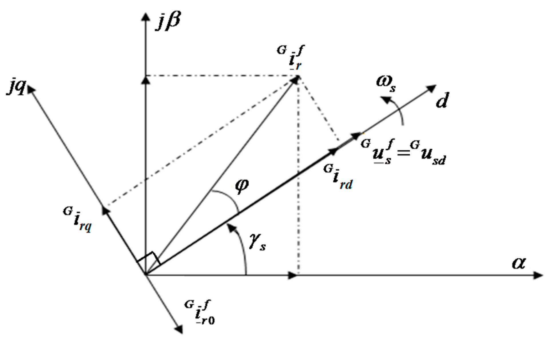
The above equation shows that the phase of the stator voltage is equal to the phase of the stator flux plus π/2.
creates the flux, so the phase of is equal to the phase of the flux, so the phase of is equal to the phase of the stator voltage minus π/2. Thus, in the grid voltage-orientated coordinates, () is a base component to create the q axis component of the rotor current (). The phase of the d axis component of the rotor current () is equal to the phase of minus π/2, or is equal to the phase of plus π/2. The vector graph in the grid voltage-orientated coordinates is shown in Figure 2.
3.3. Controlling the System in the Grid-Connected Mode
In the grid-connected mode, the DFIG stator feeds the current to the grid. The DFIG rotor current is .
Where: is the DFIG rotor current in the grid-disconnected mode. () is created in order that the DFIG stator feeds the current to the grid. Substituting and for (9c), the DFIG stator flux is as follows:
Substituting for (9a), the DFIG stator voltage is:
The voltage in is very small, so this voltage can be ignored. Thus, is written as:
The DFIG stator voltage must coincide with the grid voltage and be steady. Combining in Equation (17) with in Equation (11):
Analyzing the components of :
3.4. Controlling the DFIG Stator Power
Substituting (19a) for (20a) and (19b) for (20b):
where:
where: is created by ; and is created by rotating the vector by angles π/2.
Substituting and for (21a,b):
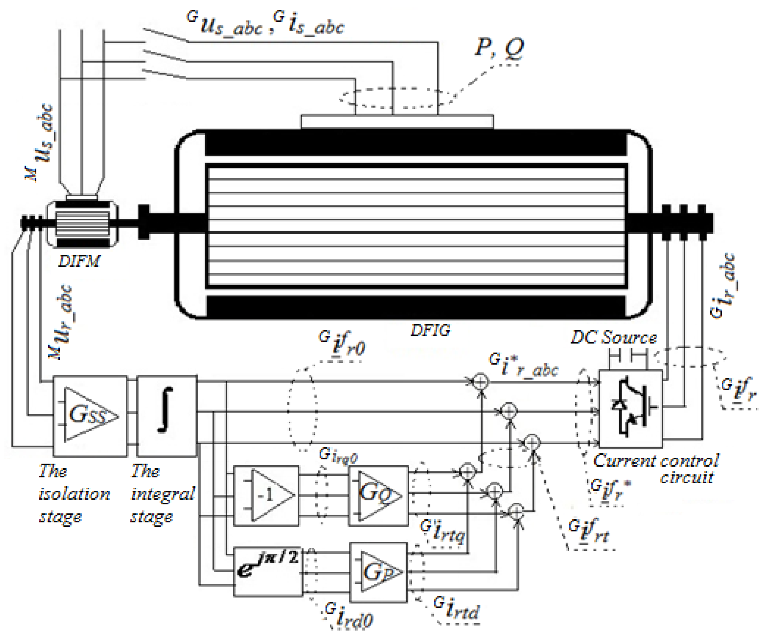
In the grid voltage-orientated coordinates, are steady, so X and Y are steady. Thus, the reactive and active power can be controlled by adjusting Gq and Gp separately. The system block diagram is shown in Figure 3.
4. Building the Model to Demonstrate the Correctness of the Proposed Structure
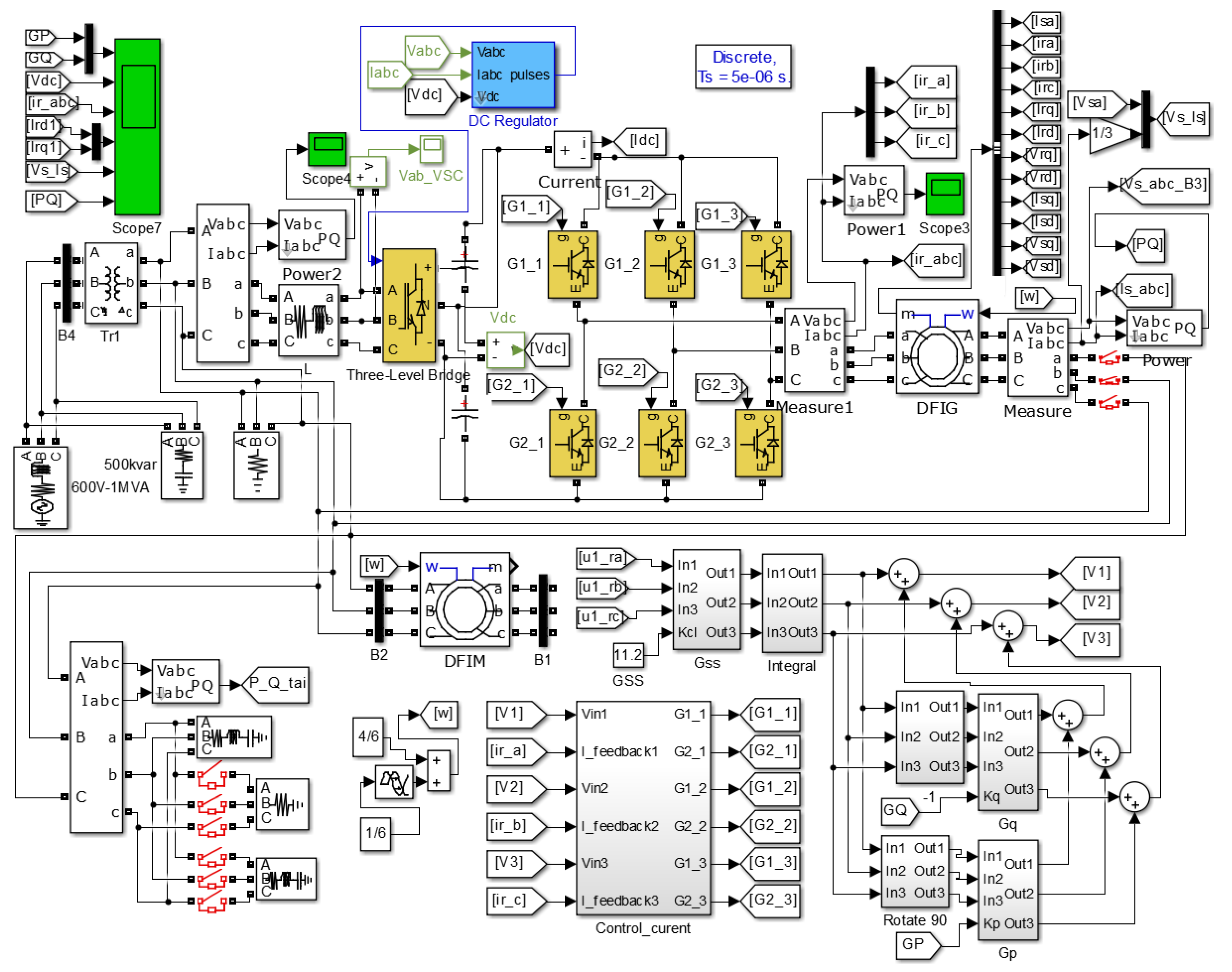
In the above section, based on the DFIG equations, the author proposed a control structure and demonstrated its ability to control the system. For clarity, in this section, the author will build circuits and emulate systems using the Matlab-Simulink software (R2014b, MathWorks Inc., Natick, MA, USA).
Based on the system structure in Figure 3, building the system includes:
- DFIM with the stator connected to the grid and the rotor functioning in high-resistance mode.
- The isolation stage, which is a circuit with a high-resistance input, so the DFIM rotor is connected to the high resistance.
- The integral stage, which is a circuit in which output signals are created by integrating the input signal.
- The current control circuit, which creates the currents fed into the DFIG rotor.
- The stage, which creates the output signals in order that the phases of the output signals are equal to the phases of the input signals plus π/2.
- The amplifying stage Gq: Based on (23b), the reactive power of the DFIG stator can be controlled by adjusting Gq.
- The amplifying stage Gp: Based on (23a), the active power of the DFIG stator can be controlled by adjusting Gp.
- DFIG, which is the doubly-fed induction generator that creates the currents fed into the grid.
All of the above stages are available in Matlab-Simulink. These stages’ fabrication techniques in practice are very easy. The details are as follows:
- Four amplifier stages, such as Gss, Gp, Gq, (−1), and one integral stage are available in the library of Matlab-Simulink.
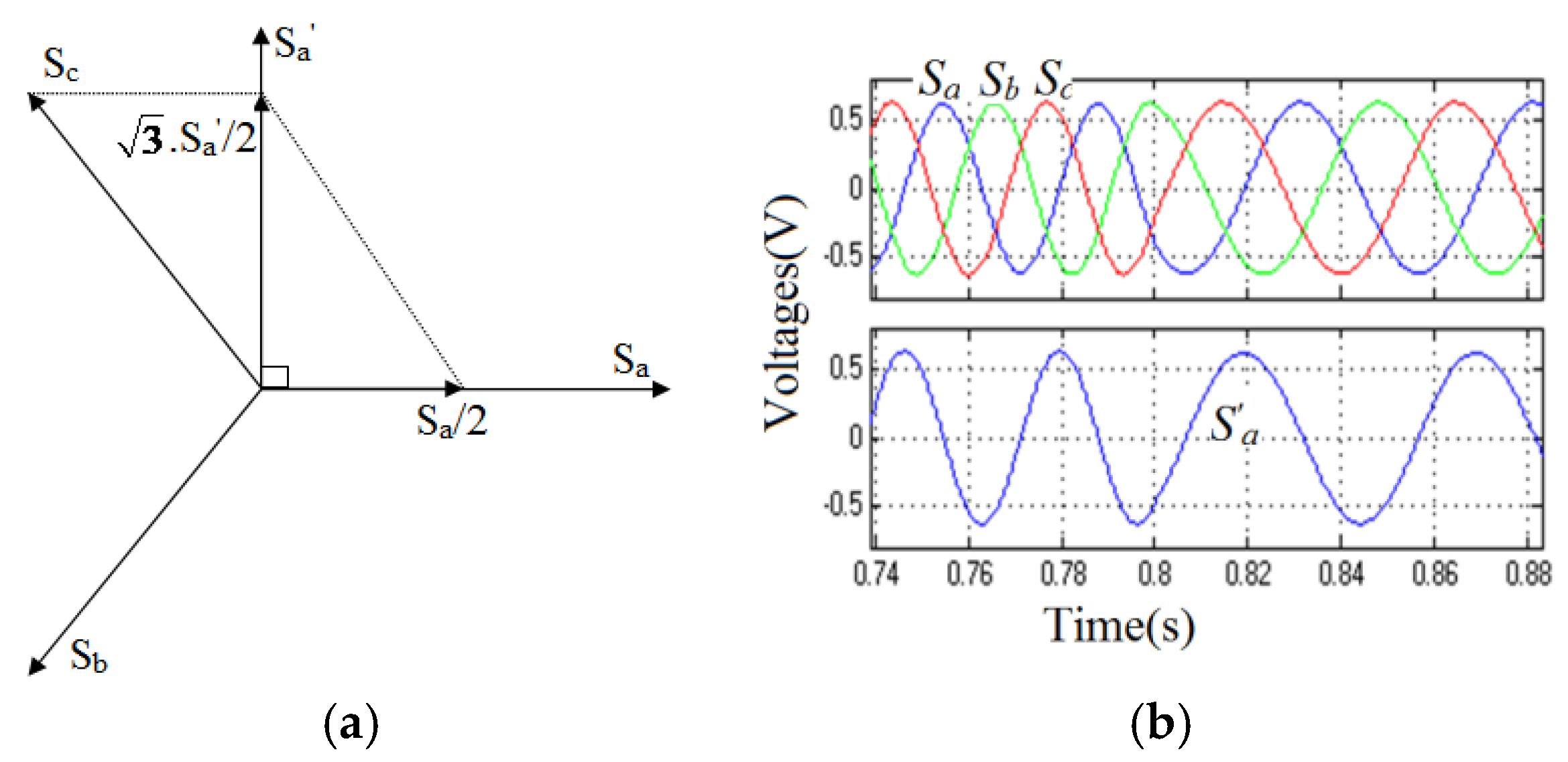
Running the stage with input signals (Sa, Sb, Sc), the A-phase output signal (Sa’) is presented in Figure 4b.
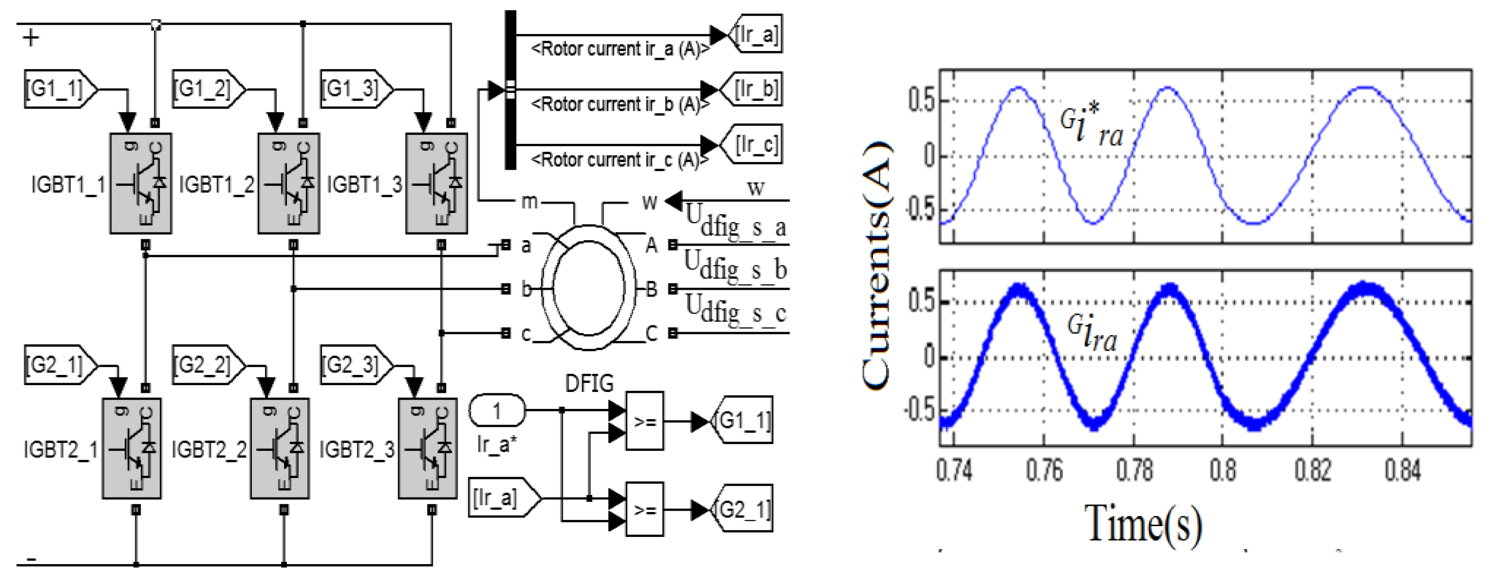
The current control circuit has three phases (Figure 5a), and each phase is controlled by two IGBTs independently. For example, the A-phase with the desired current value (i*ra) and the actual current value (ira). If i*ra is less than ira, G1_1 is turned off, and G2_1 is turned on to decrease ira; otherwise, G1_1 is turned on, and G2_1 is turned off to increase ira. Running this circuit, the results are shown in Figure 5b.
- The other stages: The other generator, 600V-1MVA, the transformer, TR1, the wire, L, the rectifier circuit with three level bridges, the voltage measurement device, the current measurement device, the breaker, etc.
5. The Results and Discussion
5.1. Before the DFIG Stator Is Connected to the Grid (the Grid-Disconnected Mode)
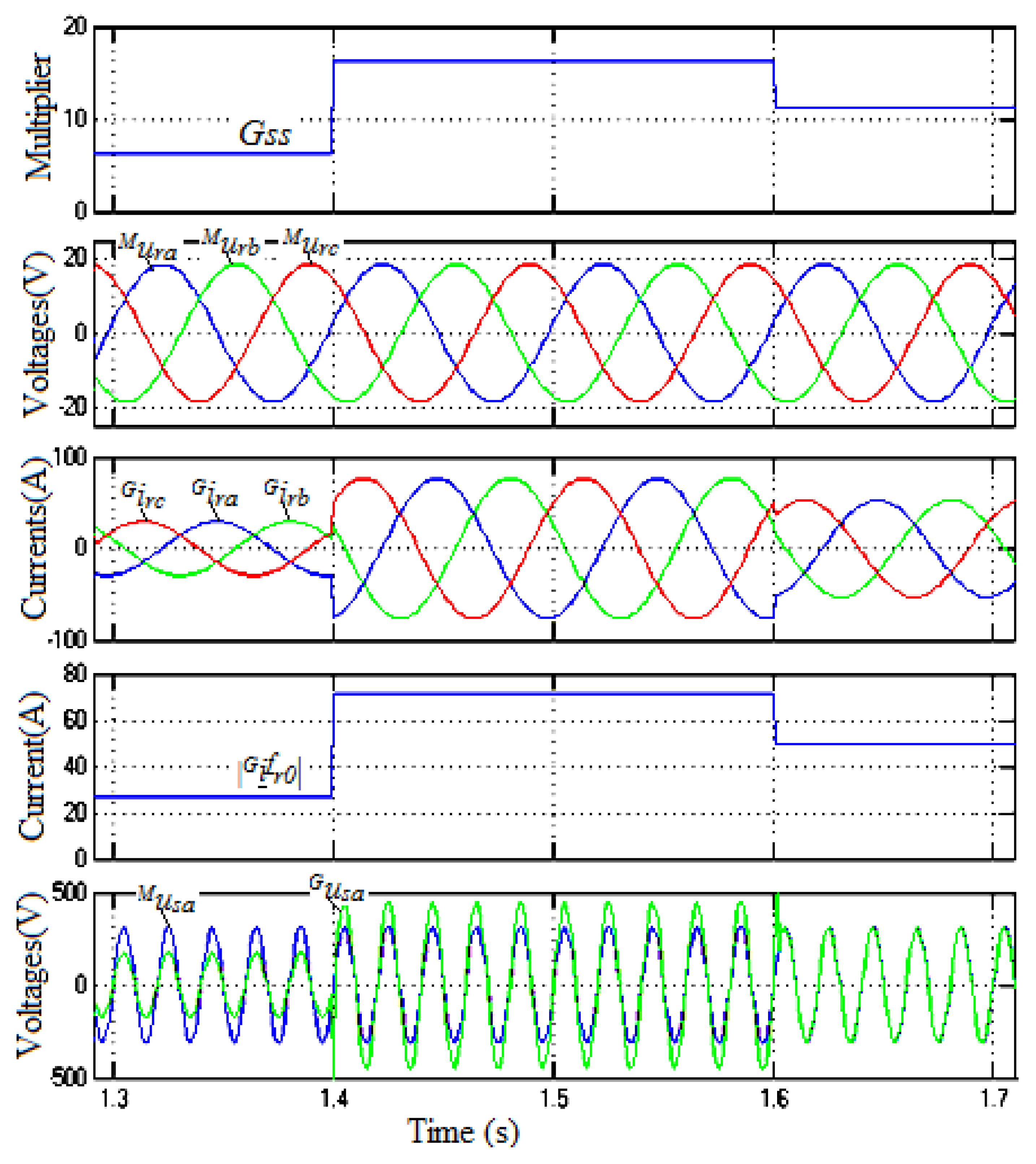
Gp and Gq are set to zero. The multiplier Gss is adjusted in order that the DFIG stator voltage coincides with the grid voltage. The signals during the adjustment of Gss are shown in Figure 7.
The DFIG stator generates the voltages (example in the A-Phase: ), with the phase and frequency being always equal to the phase and frequency of the grid voltage. Thus, in order for the DFIG stator to be connected to the grid, we only need to adjust the amplitude of . The simulation results show that if the value of Gss increases, the amplitude of increases. If the value of Gss decreases, the amplitude of decreases. At time=1.6s and setting Gss = 11.2, the amplitude of is equal to the amplitude of the grid voltage (), so the DFIG stator can be connected to the grid.
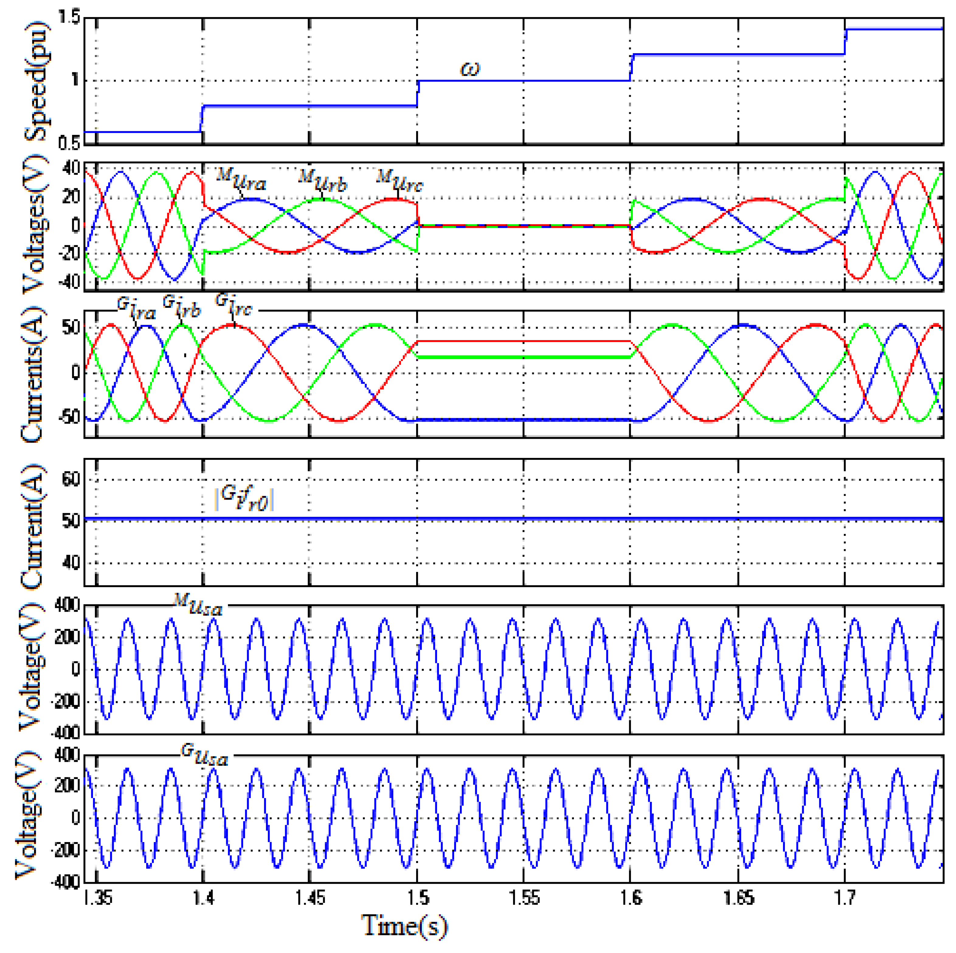
Next, the model was run to test the ability of the DFIG stator voltage () to coincide with the grid voltage () in the case of the changing of the rotor speed (ɷ) and the grid voltage.
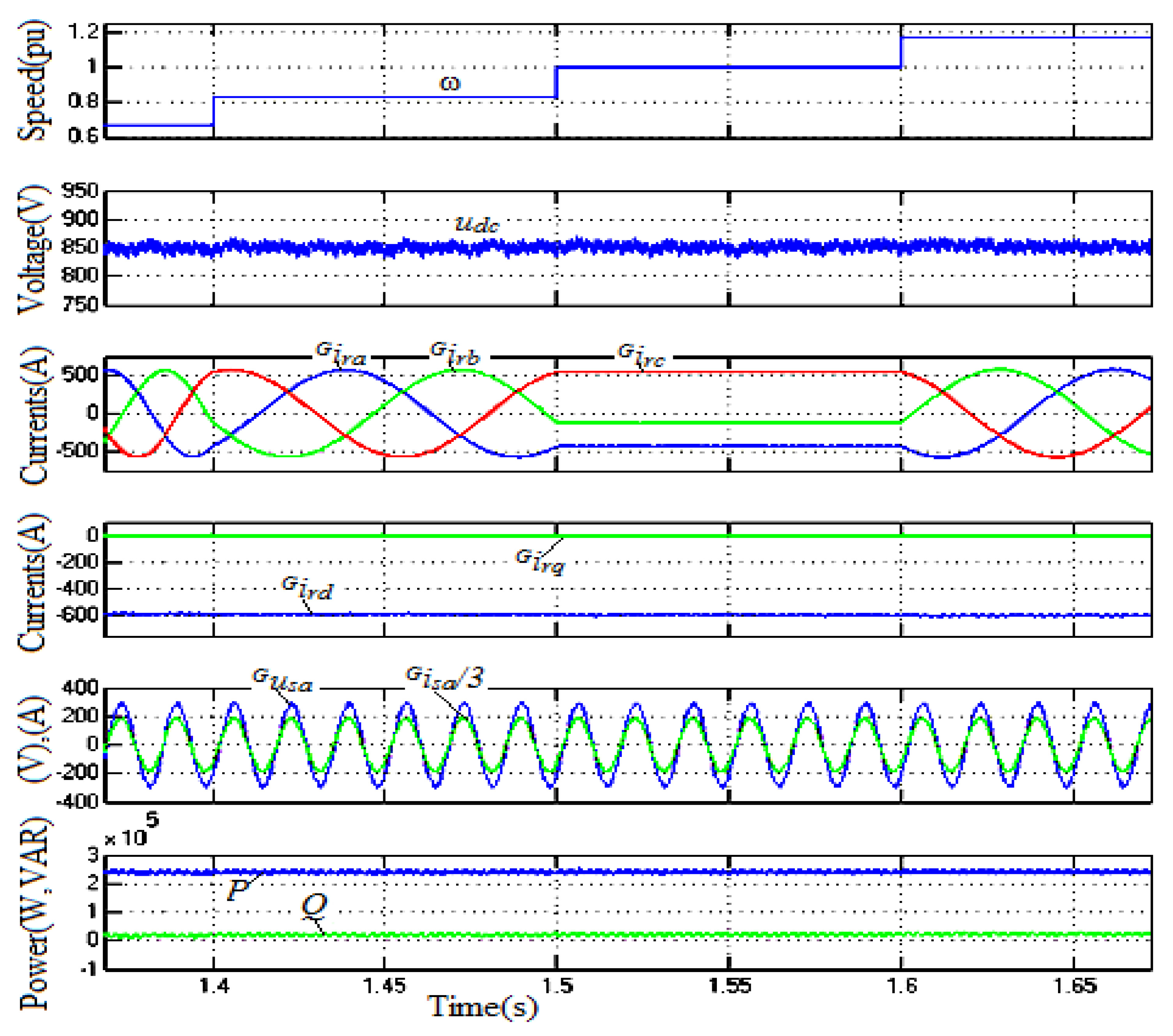
The ability to coincide with the grid voltage of the generator in the case of the changing of ɷ is shown in Figure 8. When ɷ is closer to 1 pu (synchronous speed), the frequency and amplitude of DFIM rotor voltages () are reduced, the DFIG rotor current () and amplitudes are steady, and the frequencies are reduced. When ɷ is equal to 1 pu, are zero, and become the steady ones. Finally, and always have an equal frequency, equal amplitude, and equal phase. Thus, in the case of the changing of the rotor speed, the DFIG stator voltage always coincides with the grid voltage.
In addition, the simulation results in Figure 8 show that when changing the rotor speed (ɷ), the DFIG rotor current () in the grid voltage-orientated coordinates is constant, and this result coincides with the above conclusions. is constant, so is the base component for modulating the d, q axis component of the DFIG rotor current (,) in the grid voltage-orientated coordinates.
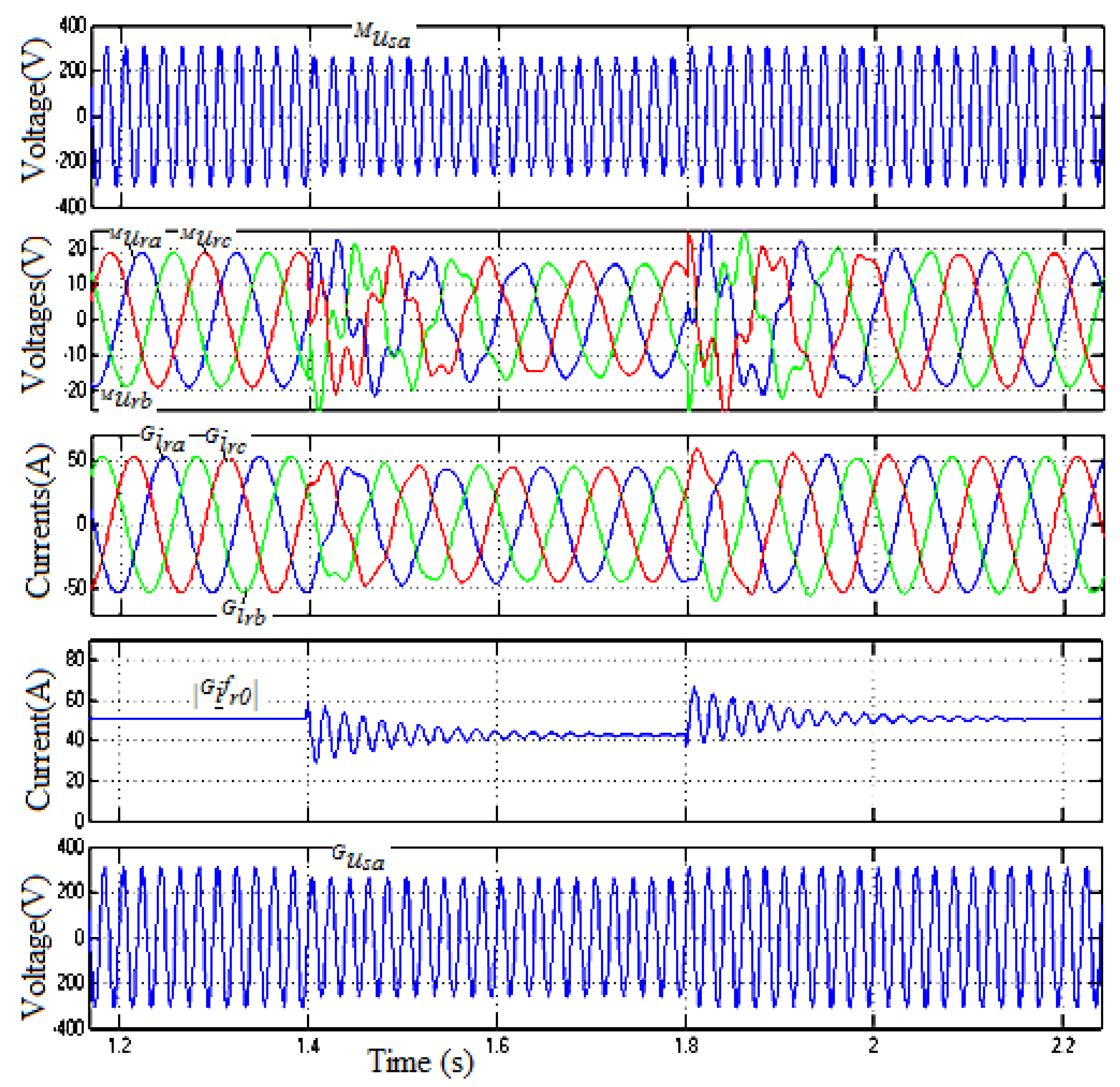
When the grid voltage () is reduced, the ability to coincide with the grid-voltage of the generator is shown in Figure 9. The DFIM rotor voltages () and the DFIM rotor currents () are changed, but the DFIG stator voltage () always coincides with the grid voltage ().
In grid-disconnected mode, the conclusion is that, after adjusting Gss, the DFIG stator voltage always coincides with the grid voltage, even when the grid voltage and the rotor speed are changing. This is a very good condition for connecting the DFIG stator to the grid.
5.2. Controlling the System in the Grid-Connected Mode
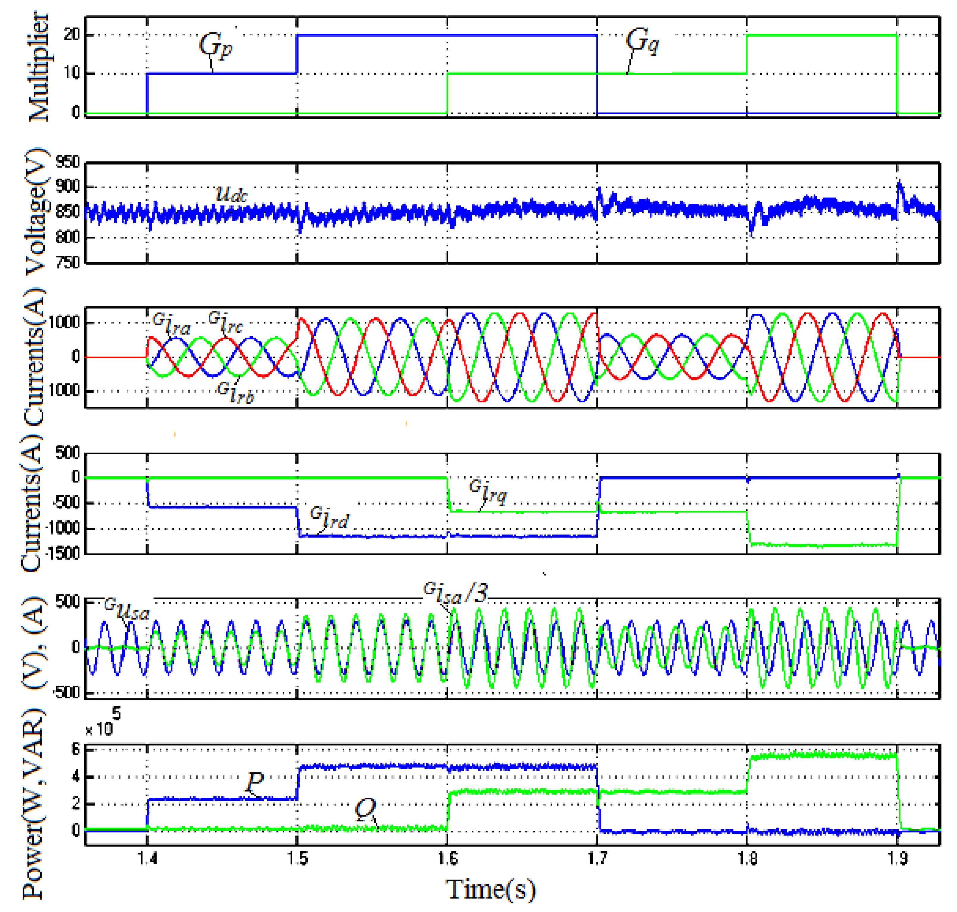
When the DFIG stator is connected to the grid, it is very easy to control Q and P separately by adjusting Gq and Gp. The simulation results are shown in Figure 10.
In the period before 1.4 s and after 1.9 s, setting Gp and Gq to zero, the result is = 0 (A), so P = 0 and Q = 0.
In the period from 1.4 s to 1.6 s, Gp ≠ 0 and Gq = 0. The simulations show that the phase of the DFIG stator current is equal to the phase of the grid voltage (example in the A Phase: ,), so the DFIG stator feeds the active power to the grid. In addition, if Gp increases by double, the DFIG stator current amplitude increases by double, and the active power increases by double.
From 1.7 s to 1.9 s, Gq ≠ 0 and Gp = 0. The simulations show that the phase of the DFIG stator current is faster than the phase of the grid voltage at an angle of π/2, so the DFIG stator feeds the reactive power to the grid. In addition, if Gq increases by double, the stator current amplitude increases by double, and the reactive power increases by double.
Thus, these simulation results show that it is very easy to control Q and P by adjusting Gq and Gp separately.
Next, when changing the rotor speed (ɷ), the stability of the system is shown in Figure 11. Setting Gp = 10 and Gq = 0, the simulation results show that the DFIG rotor currents () are changed, but the DFIG stator current (example in the A Phase: ) is not changed, so P and Q are not changed. Thus, it is confirmed that the system is stable when the rotor speed is changed.
The reaction of the system in the case of the changing of the grid voltage is shown in Figure 12.
With simple conventional power generation systems, when the DFIG stator is connected to the grid, if the grid voltage is reduced, the voltage difference between the generator terminal and the grid is increased rapidly, so the generator is over-current. However, in this proposed system, the simulation results show that, if the grid voltage is reduced, the DFIG stator current fed into the grid is decreased, so the DFIG stator power fed into the grid is decreased. Thus, the natural reaction of the system is suitable for the case of dropping the grid voltage, because the generator is not over-current.
In summary, the simulation results show that, when the DFIG is not connected to the grid, the natural characteristics of the system are such that the DFIG stator voltages and the grid voltages have an equal phase and equal frequency. We only need to adjust the amplitude of the DFIG stator voltage to make it equal to that of the grid-voltage by adjusting Gss. After this, the DFIG stator voltages always coincide with the grid voltages, even when the grid voltage and the rotor speed are changed. This is a very good condition for connecting the stator DFIG to the grid. In the grid-connected mode, it is very easy to control P and Q by adjusting Gp and Gq separately. Therefore, controlling the power of the generator fed into the grid will be convenient and effective.
6. Conclusions
This paper presents a novel method for controlling DFIG connected to the grid. This new method has been fully demonstrated by the author in both theory and simulation. Compared with the previous system, the proposed system needs small DFIM more to generate the rotor signal, but it ignores the encoder. The natural feature of the proposed system is that the output voltage always coincides with the grid voltage. All stages are very simple, and the control system does not need the coordinate conversion stages, so it is easy and cost-effective to fabricate the generator system.
When the DFIG stator is disconnected from the grid, the DFIG stator voltages and the grid voltages have an equal phase and equal frequency. Thus, in order for the DFIG stator to be connected to the grid, we only need to adjust the amplitude of the DFIG stator voltage by adjusting Gss. After this, the DFIG stator voltages always coincide with the grid voltages, even when the grid voltage and the rotor speed are changed. This is a very good condition for connecting the stator DFIG to the grid.
When the DFIG stator is connected to the grid, it is very easy to control P and Q by adjusting Gp and Gq separately.
Based on this novel method, the structure of the control system is very simple, and the generation system operates easily and effectively. This system is suitable for energy generation system applications with a variable speed, particularly on ships with an unstable grid voltage.
However, the limitation of this study is that it does not offer a solution to the problem of the generator supplying loads independently when the generator is not connected to the grid. Further studies will overcome the above limitation and present practical application results for ships. Therefore, it will be possible to show more clearly the effectiveness of the proposed method.
Funding
This research received no external funding.
Conflicts of Interest
The author declares no conflict of interest.
Nomenclature
| Symbol | Unit | Definition |
| , | V | Stator, rotor voltage vector in the grid voltage-orientated coordinates |
| , | A | Stator, rotor current vector in the grid voltage-orientated coordinates |
| , | Wb | Stator, rotor flux vector in the grid voltage-orientated coordinates |
| , | A | Stator, rotor current vector in the rotor shaft-orientated coordinates |
| V | Rotor voltage vector in the rotor shaft-orientated coordinates | |
| V | Stator voltage vector in the stator-fix-orientated coordinates | |
| Wb | Stator flux vector in the stator-fix-orientated coordinates | |
| Ω | Stator, rotor resistance | |
| H | Stator, rotor, mutual inductance | |
| ɷs, ɷr | pu | Stator, rotor electrical angular velocity |
| ɷ | pu | Rotor speed |
| P | W | Active power |
| Q | VA | Reactive power |
| A | d, q components of the stator current | |
| A | d, q components of the rotor current | |
| V | d, q components of the rotor voltage | |
| V | d, q components of the stator voltage |
References
- Rana, M.M.; Li, L.; Su, S.W. Controlling the renewable microgrid using semidefinite programming technique. Int. J. Electr. Power Energy Syst. 2017, 84, 225–231. [Google Scholar] [CrossRef]
- Rana, M.M.; Li, L.; Su, S.W. Distributed dynamic state estimation over a lossy communication network with an application to smart grids. In Proceedings of the 2016 IEEE 55th Conference on Decision and Control (CDC), Las Vegas, NV, USA, 12–14 December 2016; pp. 6657–6662. [Google Scholar]
- MAN B&W Diezel A/S, Shaft Generators for the MC and ME Engines, Denmark. 2004. Available online: http://marineengineering.co.za/education/information/electrical (accessed on 30 March 2018).
- Xia, K.; Zhang, Z.; Wang, N.; Zhang, P. Operation control and simulation research of the variable-speed constant-frequency system of the ship shaft generator. In Proceedings of the 2016 IEEE Region 10 Conference (TENCON), Singapore, 22–25 November 2016; pp. 301–304. [Google Scholar]
- Gao, J.; Wan, S.; Liu, L. The research of marine shaft generator system based on brushless doubly-fed machine. In Proceedings of the 17th International Conference on Electrical Machines and Systems, Hangzhou, China, 22–25 October 2014; pp. 151–155. [Google Scholar]
- Bodson, M. Speed Control for Doubly Fed Induction Motors with and Without Current Feedback. IEEE Trans. Control Syst. Technol. 2019. [Google Scholar] [CrossRef]
- Boutoubat, M.; Mokrani, L.; Zegaoui, A. Power quality improvement by controlling the Grid Side Converter of a wind system based on a DFIG. In Proceedings of the 2017 6th International Conference on Systems and Control (ICSC), Batna, Algeria, 7–9 May 2017; pp. 360–365. [Google Scholar]
- Tang, H.; He, W.; Chi, Y.; Tian, X.; Li, Y.; Wang, Y. Impact of grid side converter of DFIG on sub-synchronous oscillation and its damping control. In Proceedings of the 2016 IEEE PES Asia-Pacific Power and Energy Engineering Conference (APPEEC), Xi’an, China, 25–28 October 2016; pp. 2127–2130. [Google Scholar]
- Yao, J.; Li, H.; Chen, Z.; Xia, X.; Chen, X.; Li, Q.; Liao, Y. Enhanced control of a DFIG-based wind-power generation system with series grid-side converter under unbalanced grid voltage conditions. IEEE Trans. Power Electron. 2013, 28, 3167–3181. [Google Scholar] [CrossRef]
- Martinez, M.I.; Tapia, G.; Susperregui, A.; Camblong, H. Sliding-mode control for DFIG rotor-and grid-side converters under unbalanced and harmonically distorted grid voltage. IEEE Trans. Energy Convers. 2012, 27, 328–339. [Google Scholar] [CrossRef]
- Mahalakshmi, R.; Viknesh, J.; Ramesh, M.G.; Vignesh, M.R.; Sindhu Thampatty, K.C. Fuzzy Logic based Rotor Side Converter for constant power control of grid connected DFIG. In Proceedings of the 2016 IEEE International Conference on Power Electronics, Drives and Energy Systems (PEDES), Trivandrum, India, 14–17 December 2016; pp. 1–6. [Google Scholar]
- Srirattanawichaikul, W.; Premrudeepreechacharn, S.; Kumsuwan, Y. A comparative study of vector control strategies for rotor-side converter of DFIG wind energy systems. In Proceedings of the 2016 13th International Conference on Electrical Engineering/Electronics, Computer, Telecommunications and Information Technology (ECTI-CON), Chiang Mai, Thailand, 28 June–1 July 2016; pp. 1–6. [Google Scholar]
- Phan, V.-T.; Lee, H.-H. Performance enhancement of stand-alone DFIG systems with control of rotor and load side converters using resonant controllers. IEEE Trans. Ind. Appl. 2012, 48, 199–210. [Google Scholar] [CrossRef]
- Xiao, S.; Geng, H.; Zhou, H.; Yang, G. Analysis of the control limit for rotor-side converter of doubly fed induction generator-based wind energy conversion system under various voltage dips. IET Renew. Power Gener. 2013, 7, 71–81. [Google Scholar] [CrossRef]
- Peng, L.; Colas, F.; Francois, B.; Li, Y. A modified vector control strategy for DFIG based wind turbines to ride-through voltage dips. In Proceedings of the 2009 13th European Conference on Power Electronics and Applications, Barcelona, Spain, 8–10 September 2009; pp. 1–10. [Google Scholar]
- Zhou, Y.; Bauer, P.; Ferreira, J.A.; Pierik, J. Operation of grid-connected DFIG under unbalanced grid voltage condition. IEEE Trans. Energy Convers. 2009, 24, 240–246. [Google Scholar] [CrossRef]
- Tapia, A.; Tapia, G.; Ostolaza, J.X.; Saenz, J.R. Modeling and control of a wind turbine driven doubly fed induction generator. IEEE Trans. Energy Convers. 2003, 18, 194–204. [Google Scholar] [CrossRef]
- Cardenas, R.; Pena, R.; Alepuz, S.; Asher, G. Overview of Control Systems for the Operation of DFIGs in Wind Energy Applications. IEEE Trans. Ind. Electron. 2013, 60, 2776–2798. [Google Scholar] [CrossRef]
- Leonhard, W. Control of Electrical Drives; Springer-Verlag: New York, NY, USA, 2001. [Google Scholar]
- Quang, N.P.; Districh, J.A. Vector Control of Three-Phase AC Machines; Springer: Berlin, Germany, 2008. [Google Scholar]
- Thang, N.T.; Ban, N.T.; Hai, N.T. A novel method for excitation control of DFIG connected to the grid on the basis of similar signals from rotor. Appl. Mech. Mater. 2013, 336, 1153–1160. [Google Scholar] [CrossRef]
- Trong, T.N.; Tien, B.N.; Thanh, H.N. Excitation control system of DFIG connected to the grid on the basis of similar signals from rotor. In Proceedings of the 2013 IEEE International Conference on Mechatronics and Automation, Takamatsu, Japan, 4–7 August 2013; pp. 738–742. [Google Scholar]
Figure 1.
The initially proposed model.

Figure 2.
The doubly-fed induction machine plays the role of generation (DFIG) rotor current vector in the grid voltage-orientated coordinates.
Figure 2.
The doubly-fed induction machine plays the role of generation (DFIG) rotor current vector in the grid voltage-orientated coordinates.

Figure 3.
The system block diagram.

Figure 4.
The stage: (a) the vector graph; (b) the signals.

Figure 5.
The current control stage: (a) the circuit; (b) the currents.

Figure 6.
The simulation system model.

Figure 7.
The signals during an adjustment of Gss.

Figure 8.
The ability to coincide with the grid-voltage of the generator when changing the rotor speed.
Figure 8.
The ability to coincide with the grid-voltage of the generator when changing the rotor speed.

Figure 9.
The ability to coincide with the grid-voltage of the generator when changing the grid-voltage.
Figure 9.
The ability to coincide with the grid-voltage of the generator when changing the grid-voltage.

Figure 10.
The process of adjusting P and Q through Gp and Gq.

Figure 11.
The stability of the system when the rotor speed is changed.

Figure 12.
The reaction of the system when the grid voltage is changed.


Table 1.
The parameters of DFIG and DFIM.
| U (V) | f (HZ) | S (VA) | Ls (H) | Rs (Ω) | Lm (H) | Lr (H) | Rr (Ω) | p | |
|---|---|---|---|---|---|---|---|---|---|
| DFIG | 400 | 60 | 1,000,000 | 3.9 × 10⁻⁴ | 1.56× 10⁻³ | 0.0121 | 3.95× 10⁻⁴ | 1.62× 10⁻³ | 2 |
| DFIM | 400 | 60 | 1500 | 6.93× 10⁻³ | 0.512 | 0.0511 | 3.92× 10⁻³ | 0.690 | 2 |
© 2019 by the author. Licensee MDPI, Basel, Switzerland. This article is an open access article distributed under the terms and conditions of the Creative Commons Attribution (CC BY) license (http://creativecommons.org/licenses/by/4.0/).
Share and Cite
MDPI and ACS Style
Nguyen, T.-T. A Rotor-Sync Signal-Based Control System of a Doubly-Fed Induction Generator in the Shaft Generation of a Ship. Processes 2019, 7, 188. https://doi.org/10.3390/pr7040188
AMA Style
Nguyen T-T. A Rotor-Sync Signal-Based Control System of a Doubly-Fed Induction Generator in the Shaft Generation of a Ship. Processes. 2019; 7(4):188. https://doi.org/10.3390/pr7040188
Chicago/Turabian StyleNguyen, Trong-Thang. 2019. "A Rotor-Sync Signal-Based Control System of a Doubly-Fed Induction Generator in the Shaft Generation of a Ship" Processes 7, no. 4: 188. https://doi.org/10.3390/pr7040188
Note that from the first issue of 2016, this journal uses article numbers instead of page numbers. See further details here.