Modeling, Management, and Control of an Autonomous Wind/Fuel Cell Micro-Grid System


1
Department of Electrical Engineering, Faculty of Engineering, University of Tabuk, Tabuk 71491, Saudi Arabia
2
Department of Electrical Engineering, Faculty of Engineering, Sohag University, Sohag 82524, Egypt
3
Department of Electrical Power, Faculty of Engineering, Cairo University, Cairo 12613, Egypt
*
Author to whom correspondence should be addressed.
Processes 2019, 7(2), 85; https://doi.org/10.3390/pr7020085
Submission received: 3 January 2019
/
Revised: 25 January 2019
/
Accepted: 4 February 2019
/
Published: 8 February 2019
(This article belongs to the Special Issue Modelling and Process Control of Fuel Cell Systems)
Abstract
:This paper proposes a microelectric power grid that includes wind and fuel cell power generation units, as well as a water electrolyzer for producing hydrogen gas. The grid is loaded by an induction motor (IM) as a dynamic load and constant impedance load. An optimal control algorithm using the Mine Blast Algorithm (MBA) is designed to improve the performance of the proposed renewable energy system. Normally, wind power is adapted to feed the loads at normal circumstances. Nevertheless, the fuel cell compensates extra load power demand. An optimal controller is applied to regulate the load voltage and frequency of the main power inverter. Also, optimal vector control is applied to the IM speed control. The response of the microgrid with the proposed optimal control is obtained under step variation in wind speed, load impedance, IM rotor speed, and motor mechanical load torque. The simulation results indicate that the proposed renewable generation system supplies the system loads perfectly and keeps up the desired load demand. Furthermore, the IM speed performance is acceptable under turbulent wind speed.
1. Introduction
Modern industries, transportation means, and nearly all mankind’s requirements mainly depend on electrical power. Traditionally, electrical power generation is essentially based on fossil fuel resources. Nevertheless, fossil fuels suffer from several drawbacks, such as depletion by 2050. However, the rapid growth of the world’s population increases the world electrical power demand. The global energy demand estimated 2.1% in 2017 (more than twice the average increase over the previous five years) [1]. Also, it generates harmful emissions that form the essential cause of the phenomena of global warming and many environmental problems. Energy-related carbon dioxide (CO2) emissions rose—by an estimated 1.4% in 2017—for the first time in four years, at a time when climate scientists said that emissions needed to be in steep decline [1]. Several decades ago, renewable energy resources have gained more attention as a sustainable replacement for fossil fuels. Renewable energy resources have great advantages as they are clean, do not deplete, and are available everywhere. Many renewable energy resources [2,3,4,5] have been introduced recently, such as photovoltaic (PV), wind, ocean wave, ocean tides, and micro hydro. Thanks to technology advances and rapid growth, dramatic reductions in the costs of solar PV and wind energy systems have occurred [6]. In the same context, new energy alternative technologies like biomass, geothermal, microturbines, and fuel cells (FCs) have been investigated [7]. Now, electricity generation by renewable systems is less expensive than the newly installed fossil and nuclear power plants in many parts of the world. An assessment of different renewable energy resources for electrical power production showed that wind energy is the first choice [8].
Renewable energy systems may be classified into grid-connected systems and standalone systems. The present capacities of the grid-connected renewable energy systems vary from several kilowatts of residential PV systems to large-scale wind farms. The grid-connected systems do not need any storage as the generated energy is injected directly to the grid. These systems are suitable for urban regions where the grid is available. However, standalone systems are suitable for rural areas, where grid extension is not feasible. In standalone renewable energy systems, the load is an individual house and not connected to a grid. The capacities of these systems are usually small. In some applications, several houses are connected to form a small power grid called microgrids (MGs) [9,10]. Microgrid technology has become popular in islands as it provides a cost-effective alternative where power grid extension is expensive and fuel transportation is difficult and costly [11,12].
The major obstacle for utilizing one technology of renewable energy sources is the intermittent nature of that source. That intermittent behavior of the renewable energy sources comes from the strong dependency on the environmental conditions, which are changing continuously. A suggestion to solve the intermittency problem of the renewable energy systems is the use of energy storage element. Energy storage units are classified as capacity-oriented storage systems and access-oriented storage systems. The capacity-oriented storage systems include pumped hydroelectric storage, compressed air energy storage, and hydrogen storage systems. It has a slow response and is considered long-term energy storage. Batteries, superconducting magnetic energy storage, supercapacitors, and flywheels are considered access-oriented storage systems. It has a fast time response that is useful for short duration disturbance applications [13,14,15,16]. In fact, the integration of energy storage systems with one technology of renewable energy sources has many disadvantages. One of them is the load power variations, which may harm the storage system and degrade its lifetime. On the other hand, the size and cost of the system increase [17]. Hybrid power generation systems are introduced essentially to alleviate these disadvantages. These systems contain two or more energy sources with a storage system. Hybrid renewable energy systems have benefits of high reliability, high efficiency, better power quality, and low energy storage requirements [18,19].
Usually, microgrids can operate in two modes: grid-connected mode and autonomous mode. So, the main benefit of a microgrid is that it is able to operate in both the above two modes [20]. The microgrid can then function autonomously. Both loads and generation in microgrids are usually interconnected at low levels of voltages. However, one issue regarding the microgrid is that the operator needs to be very vigilant because numbers of power system areas are connected to microgrid. Also, in microgrid generation resources can include wind, photovoltaic, fuel cells, energy storage, or other power generation sources [21].
In the literature, there are different types of standalone hybrid power sources have been reported [22,23,24,25,26,27]. They usually combine solar energy and/or wind energy with another green power source such as FC, biomass, etc. As the work in this paper is directed to hybrid wind/FC generation systems, we focus on the literature review of that subject. Khan et al. [28] investigates a hybrid wind/FC generation system and presented a detailed life cycle analysis of the system for application in Newfoundland and Labrador. It concludes that the system is highly nonlinear and difficult to model. Battista et al. [29] presents a wind/hydrogen power system with a novel power conditioning algorithm. It introduces a Maximum Power Point Tracking (MPPT) control strategy that was developed using concepts of the reference conditioning technique and of the sliding mode control theory. Gorgun et al. [30] presents a wind/hydrogen power system and developed the electrolyzer and hydrogen storage dynamic model. Bizon et al. [31] introduces a hybrid wind/FC generation system with a global extremum seeking a control algorithm for optimal operation of the wind turbine under the turbulent wind.
This paper presents a novel hybrid wind/FC energy system. In addition, it presents the system detailed dynamic model, the application of mine blast optimization, the controller design, the performance analyses, and the simulations of the developed system under the turbulent wind speed.
In this study, the microelectrical power grid is managed and controlled based on an optimal controller using mine blast algorithm. The proposed microgrid system mainly consists of R-L static load, IM as a dynamic load, a wind generation system, FC generation system, water electrolyzer, uncontrolled rectifier, and controlled DC/AC converter.
The power system management is adapted to make the wind power generation is the master source for the loads. Also, hydrogen gas is produced using a water electrolyzer during wind power generation peaks. Hydrogen is fed back to the FC system adding to its energy storage.
The main contribution of this study can be seen from the obtained results that the proposed renewable generation system can supply the system loads perfectly in addition to a better prediction of the electrical parameter waveforms. Also, the controller response follows up the desired load demand with a small maximum overshoot and little settling time. In addition to, the generated power is managed such that the load required power is supplied by the wind power and the more needed power is covered by the fuel cell generation unit.
This paper is arranged as follows. Section 2 includes the discussion of the system description. Section 3 presents the proposed system dynamic model. Details of the system controllers are found in Section 4. The simulation results and their discussion are presented in Section 5. Finally, Section 6 shows the conclusions.
2. System Description
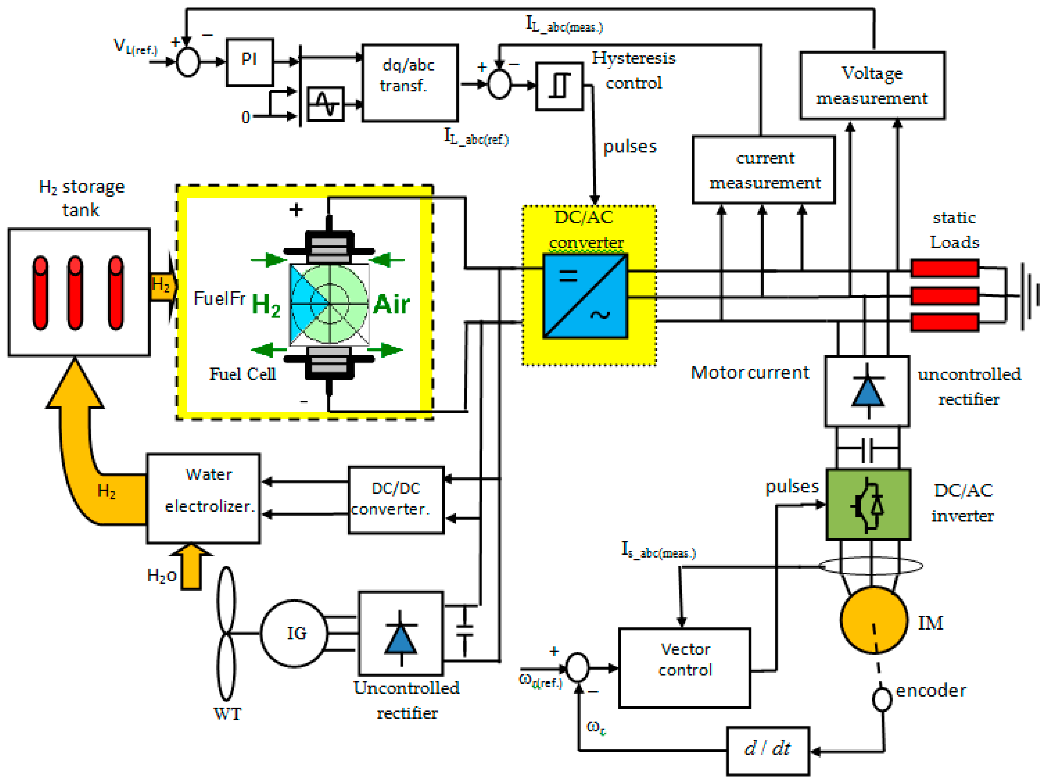
The proposed system is a hybrid wind/FC microgrid supplies two loads, as shown in Figure 1. The wind turbine drives a 3-φ Induction Generator (IG) The output voltage of the IG is rectified via a diode rectifier producing the Direct Current (DC) bus voltage. That bus supplies a water electrolyzer that produces hydrogen gas to be saved in the FC generator. Then, the output voltage of the FC is connected to the system DC bus. In addition, the DC bus supplies the 3-φ inverter that converts DC power into Alternating Current (AC) power to feed the system loads. General R-L impedance represents the static load. In addition, the dynamic load is a speed controlled induction motor. That inverter is controlled in such a way to supply loads with a regulated AC voltage and frequency.
Usually, wind speed variations cause the IG output power to vary as well. Therefore, an FC unit supplies power to loads when the power of the wind generation unit drops. Hence, it acts as a slave to compensate for any decrease in the generated wind energy. In addition, it can supply additional power demanded by the loads.
Frequently, the load voltage of the system is not regulated due to the speed variations of the wind and load changes. Therefore, the voltage controller is used for the main inverter to regulate the load voltage and frequency. Also, the optimization algorithm is applied to control the speed of a vector controlled induction motor.
3. The Dynamic Model of the System
The detailed dynamic model of all proposed system components will be discussed in the following paragraphs.
3.1. Wind Turbine Model
The power output of the wind turbine can be represented as [32]
where, A = πR2 is the swept area (m2) by the blades, β is the blade pitch angle (in degrees), R is the radius of the turbine blade, vw is the wind speed, ρ is the air density (kg/m3), λ is the tip–speed ratio as defined by Equation (2), Cp is the performance coefficient of the turbine that is given by Equation (3), and ωm is the turbine mechanical angular rotor speed.
The wind turbine torque (Tm) is related to its power by the classical relation:
The dynamic equation of the wind turbine and the electrical generator mechanical system can be written as
where, Te is the electrical generator electromagnetic torque (N·m), J is the combined inertia of the generator rotor and the wind turbine (kg·m), and B is the mechanical viscous friction (N·m·s/rad).
3.2. Dynamic Model of the Induction Machine
In a synchronous reference frame, the induction motor dynamic model may be represented by [33]
where, rr is the rotor resistance; (vds and vqs) are the stator d- and q-axis voltage components, respectively; (ids and iqs) are the stator d- and q-axis current components, respectively; (λdr and λqr) are the rotor d- and q-axis flux linkage components, respectively; (Ls, Lr, and Lm) are the stator inductance, rotor, and mutual inductances, respectively; ωr is the motor speed; ωs is the motor synchronous speed; Tem is the motor electromagnetic torque (N·m); Jm is the inertia of the IM rotor (kg·m); and Bm is the viscous friction of the coupling (N·m·s/rad).
3.3. Fuel Cell Model
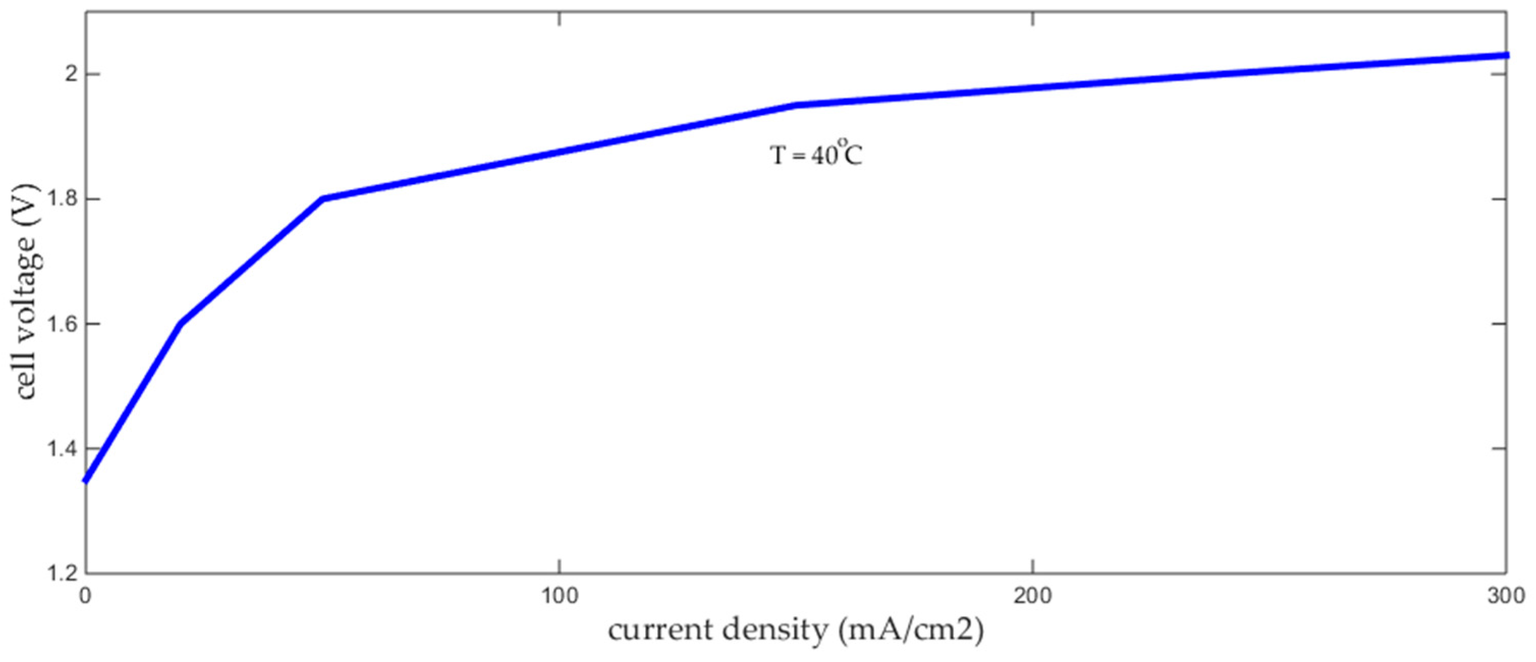
Typically, the Proton-Exchange Membrane Fuel Cell (PEM FC) has an electrical characteristic at normal environmental conditions as shown in Figure 2. Normally, FCs are subjected to internal voltage losses that cause a voltage drop beyond the nominal voltage values. Three kinds of voltage losses are presented: the ohmic polarization, the concentration polarization, and the activation polarization. The slowness of the chemical reactions is the cause behind the cell activation losses; it can be reduced by maximizing the catalyst contact area. However, the cause of the resistive losses is the resistance of all the FC electrical circuit and their connections. This part of losses can be alleviated by well hydrating the membrane. Finally, the concentration losses come from the changes in gas concentration at the electrodes surface.
The model of the PEM FC is given by [34,35,36]
where, E is the stack output voltage, Eo is the cell open circuit voltage at standard pressure, N is the number of cells in stack, F is Faraday’s constant, n is the number of transferred electrons in the electrochemical reaction, R’ is the universal gas constant, T is the operating temperature, PH2 is the partial pressure of hydrogen, PO2 is the partial pressure of oxygen, PH2Oc is the partial pressure of gas water, Pstd is the standard pressure, Vdrop is the voltage losses, i is the output current density, in is the internal current density related to internal current losses, io is the exchange current density related to activation losses, iL is the limiting current density related to concentration losses, and α is the area specific resistance related to resistive losses.
3.4. Uncontrolled Rectifier Model
The IG speed is directly related to the wind speed that changes usually with time. Hence, the IG output voltage is not regulated in terms of its magnitude or frequency. This issue is not suitable for many applications that require regulated sources. That problem can be alleviated by rectifying the IG output voltage to form the DC bus then converting it to an AC voltage via a power inverter. The rectifier is simply a diode bridge rectifier. Neglecting the source inductance, the average model of the rectifier is given by [37]
where, (Ig, Vg) are the phase RMS current and voltage of the IG, respectively, and (Id, Vd) are the average rectifier output current and voltage, respectively.
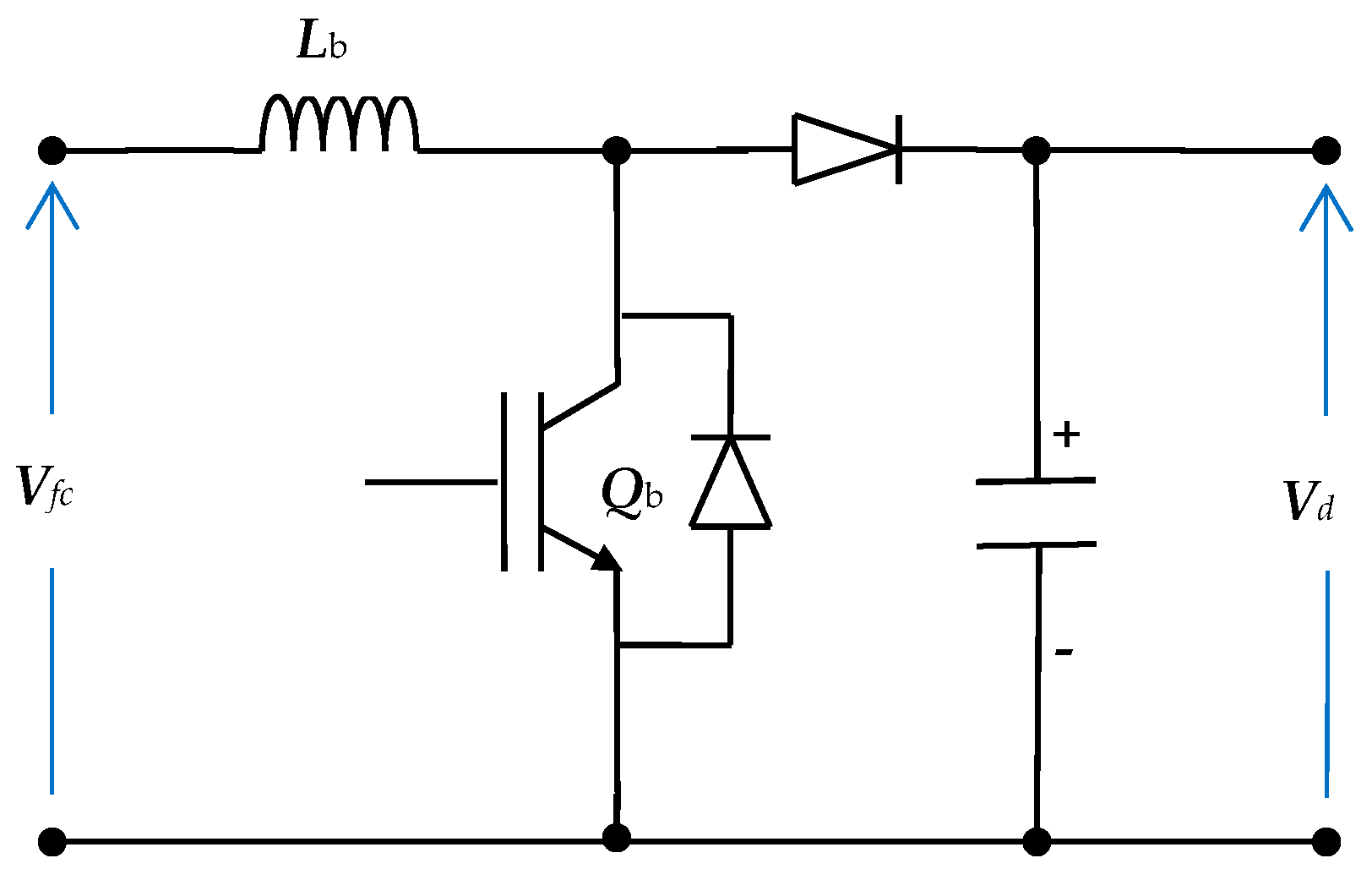
3.5. Boost Converter Model
The classical circuit diagram of the boost converter is shown in Figure 3. The input of the boost converter is the DC bus voltage. However, its output feeds the water electrolyzer. Its function is to regulate the power transfer to the water electrolyzer in turn to the fuel cell. The average model of the boost converter is given by [38]
where, d is the duty ratio of the switch and (Vfc, Ifc) are the fuel cell output voltage and current, respectively.
3.6. Main Power Inverter Model
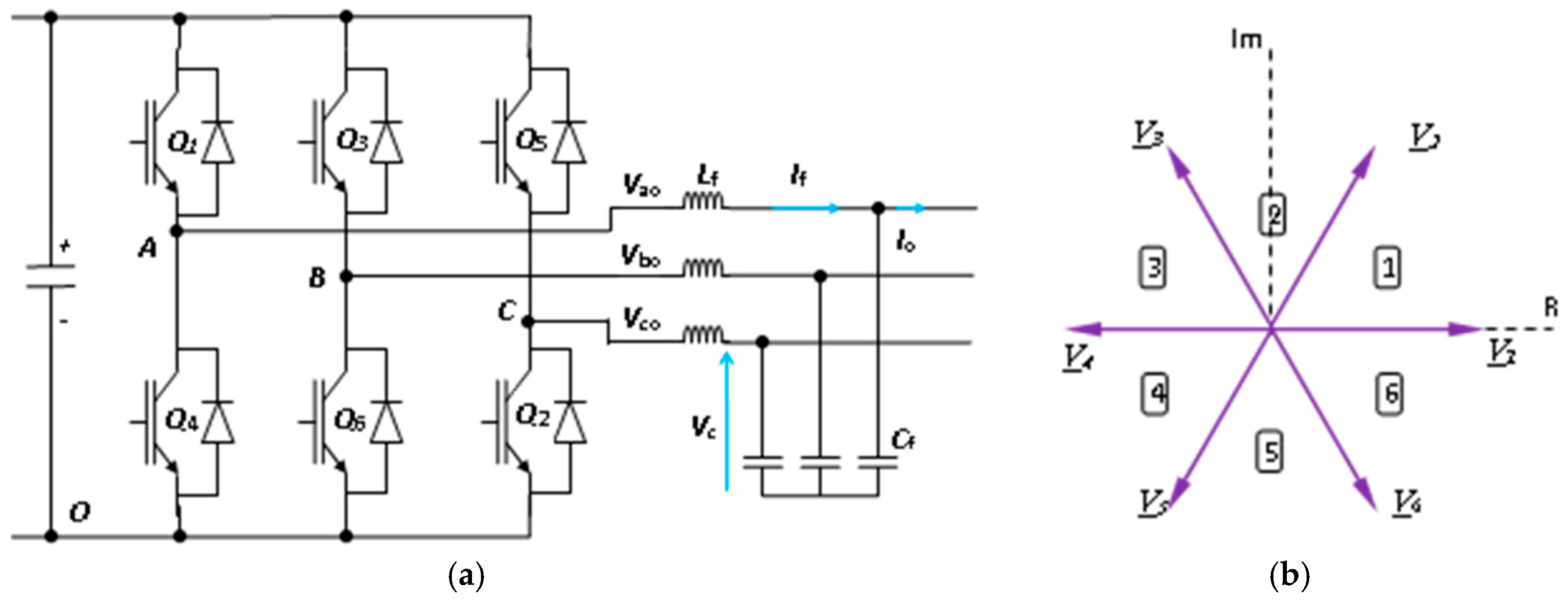
The power circuit diagram of a 3-φ inverter connected to L-C filter is shown in Figure 4a. The output voltage Vc, the inverter voltage Vi, the output current Io, and the filter current If are expressed as space vectors by
where, (fa, fb, and fc) are the phase values, F is the space vector of the quantity, and a = ej(2π/3).
The switching states of the inverter are determined by its gate signals (Sa, Sb, and Sc). These states can also be expressed as space vector S using Equation (13). Considering the possible combinations of the gate signals, there are eight switching states. These states generate eight voltage vectors as shown in Figure 4b. There are two zero voltage vectors (V0 = V7) and six active voltage vectors. The system dynamic behavior can be expressed by
where, (L, C) are the filter inductance and capacitance, respectively.
4. System Controllers
The control system of the proposed wind/FC system consists of three controllers. The first controller is the main inverter controller that regulates the load voltage and frequency. The second controller is the boost converter controller. However, the third controller is the induction motor controller that controls the speed of the induction motor. The three controllers will be discussed in the following paragraphs.
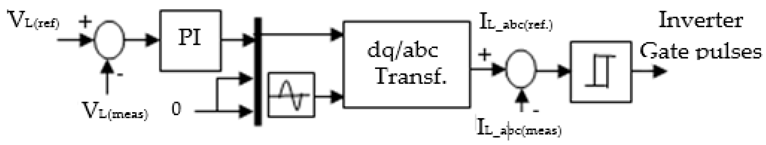
4.1. Main Inverter Controller
The proposed controller is shown in Figure 5, a current controlled voltage source inverter (VSI) is employed. The inverter output voltage is compared to the reference voltage generating an error signal. The error is sent to an optimized Proportional-Integral (PI) controller that generates the reference three-phase currents. These reference currents are compared to the actual three-phase currents producing error signals that are fed to hysteresis controllers to produce the inverter switches driving pulses.
4.2. Mine Blast Optimization Algorithm
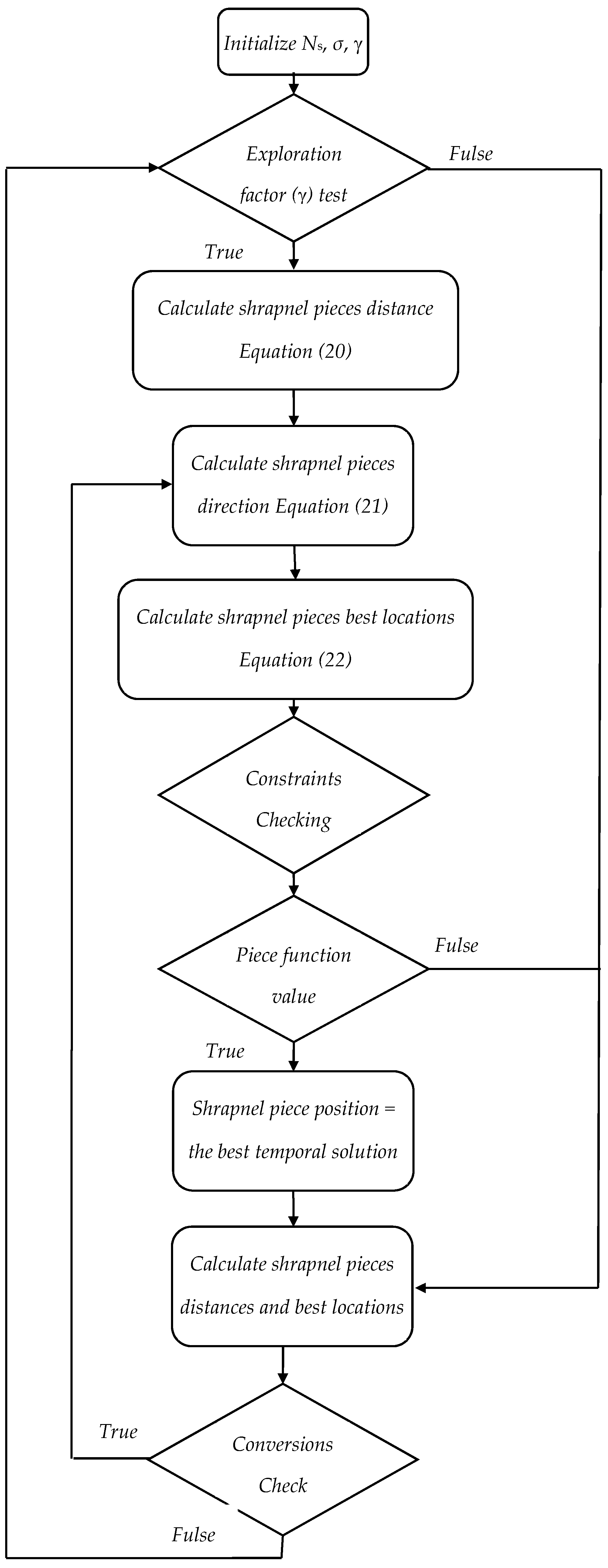
The idea behind this algorithm is the exploration technique of landmines. An initial shot point (zo) is adapted using [39,40]
where, zo is the first shot point and (SB and LB) are the problem upper and lower limits, respectively.
Assume that the population has Ns Shrapnel pieces. Mine blast algorithm has two phases named exploitation and exploration. The function of the exploitation phase is to encourage and to converge the solution. On the other hand, the exploration has the responsibility of exploring the search space. During the starting iterations of MBA, the exploration factor (γ) explores the search spaces then check the number of iterations (i). The exploration phase ends when (γ ) is greater than (i) which is given by [40]
Hence, the directions of the shrapnel pieces are given by
The best locations of the shrapnel pieces are calculated by
where is the shrapnel distance of the exploded mines, F is the fitness function, and is the best location.
Exploitation phase can be defined as
The initial distances of the shrapnel pieces are gradually reduced in the exploitation phase. This can be achieved by reducing the user to converge constant (σ). The reduction in the initial distance is determined using
The mine blast algorithm may be summarized in the flowchart of Figure 6.
Usually, MBA uses an objective function check the optimality of the resulted parameters. There are several forms of the objective function [41], such as the Integral Time Absolute Error (ITAE), Integral Square Error (ISE), and Integral Time Square Error (ITSE). Nevertheless, ITAE is selected due to its better performance. Therefore, the suggested objective function in this paper is ITAE that is given by
where, ts is the simulation time and [Kp1, Ki1, Kp2, and Ki2] are the parameters to be estimated, x =, and the constraints are assumed to be
The proposed optimal controlling parameters of MBA are given in Table 1.
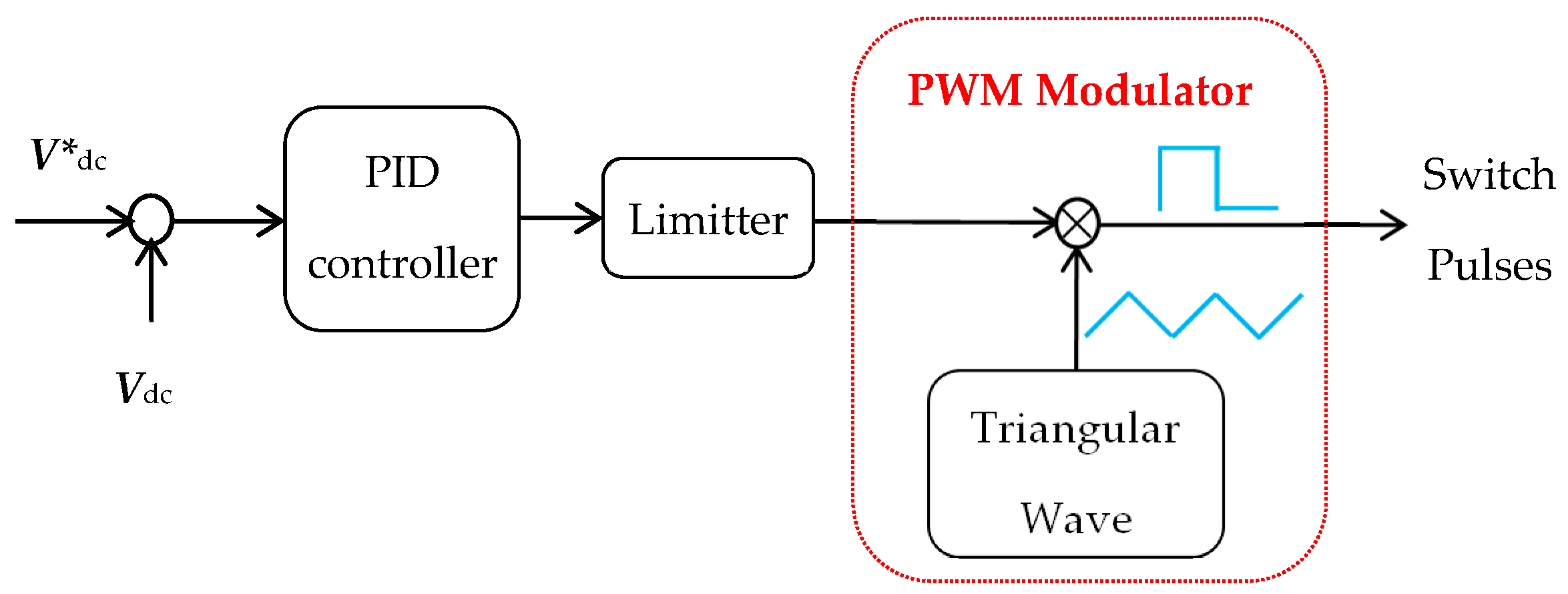
4.3. Boost Converter Controller
The boost converter control circuit is shown in Figure 7. It is a simple voltage regulator. The reference voltage signal is generated based on the voltage error. Then the error is fed to the Proportional-Integral-Differentiator (PID) controller that generates the modulating signal to the Pulse Width Modulator (PWM) unit. In turn, the PWM unit generates the suitable duty cycle pulses for the converter switch.
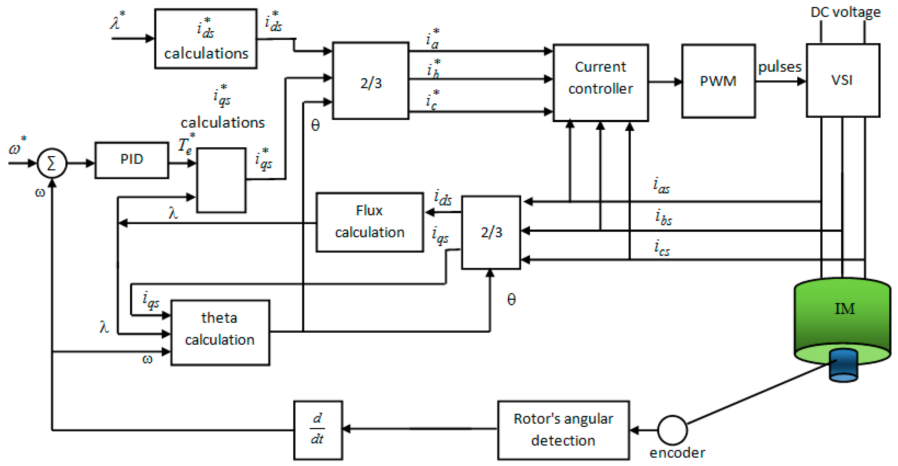
4.4. Induction Motor Controller
There are two techniques to control IM: vector and scalar control. The vector control technique is precise and has a high-performance operation. Hence, the speed of the induction motor is controlled using an optimal vector control technique as shown in Figure 8. The actual speed is measured and compared to the reference speed producing the error that is manipulated by an optimal PI controller. The controller generates the reference torque for the vector control. The rotor flux and torque of the IM are estimated using the IM model. The details of vector control and estimators are presented by Trzynadlowski et al. [42].
5. Simulation Results
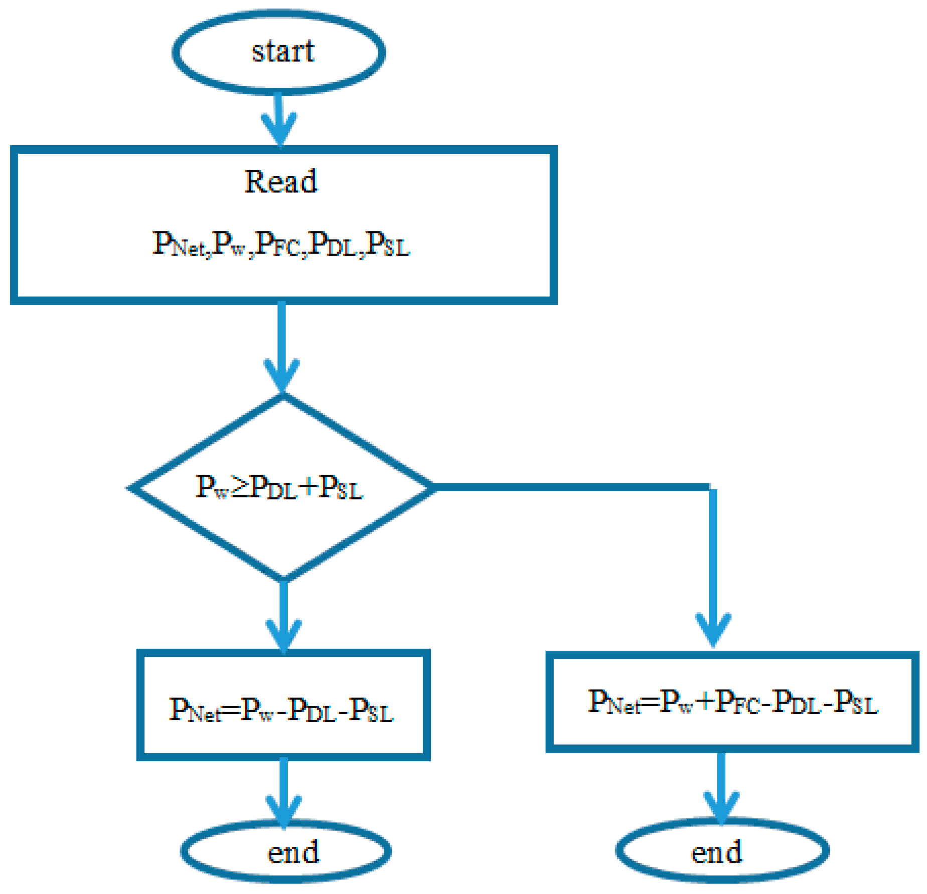
Computer simulations have been carried out to prove the performance of the proposed system under loads and wind speed changes. The proposed system shown in Figure 2 is simulated using MATLAB software package (MATLAB 16, Math Works, Torrance, CA, USA) and tested under various values of wind velocity, IM speed changes, and static load changes. The management of the energy exchange algorithm of the proposed island microgrid is shown by the flowchart of Figure 9.
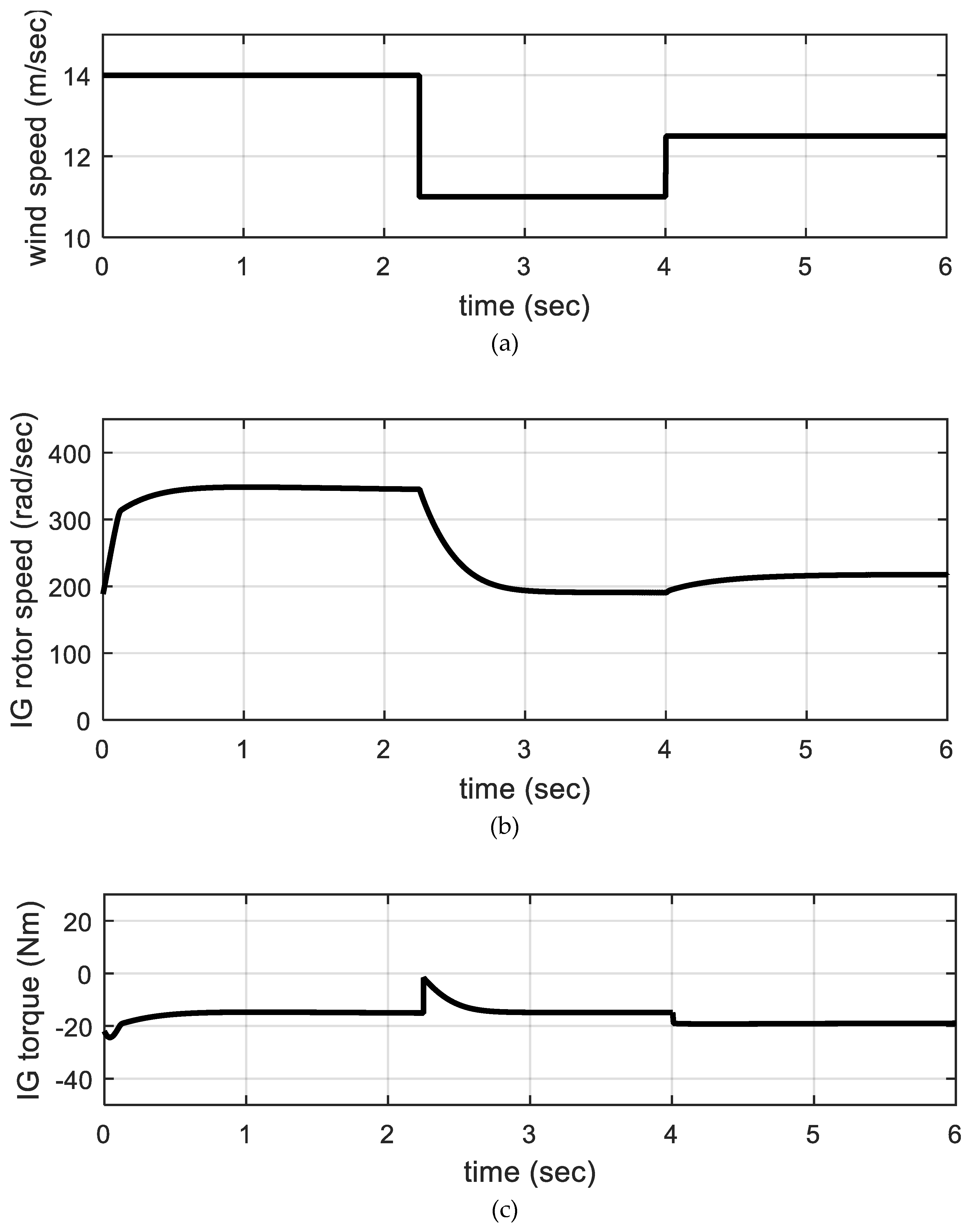
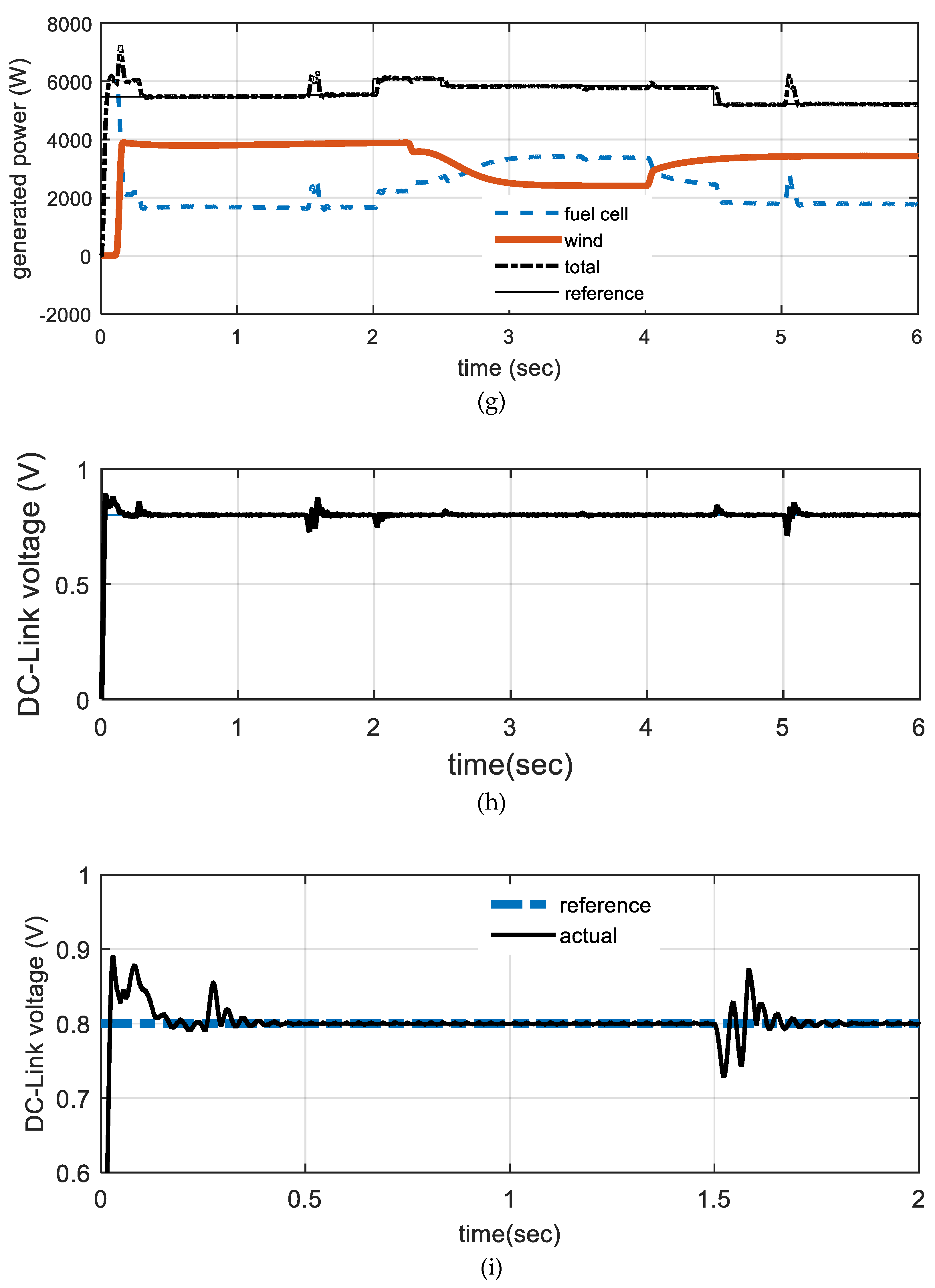
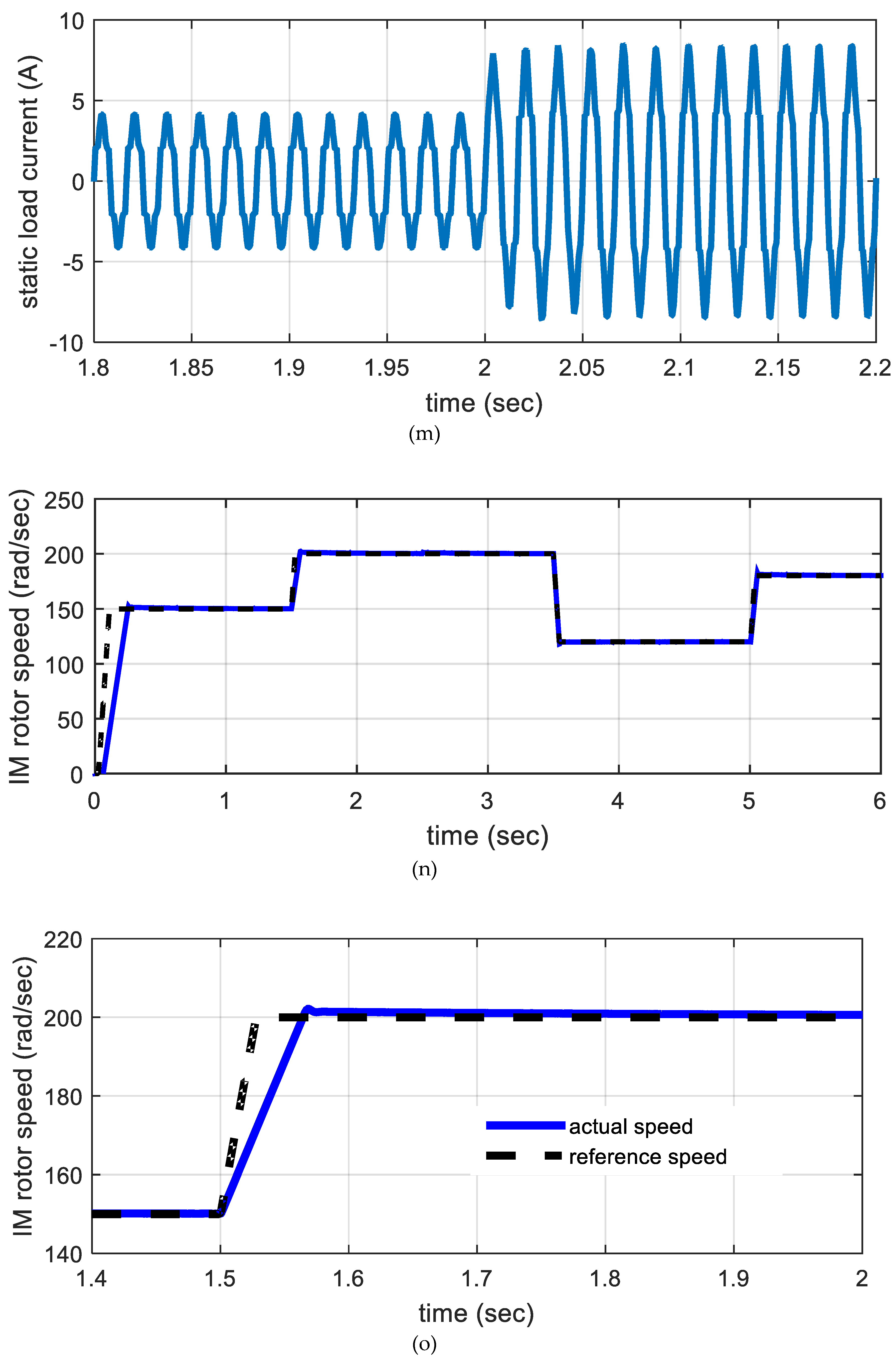
Figure 10 shows the obtained results for various system parameters like wind speed, FC power, IG (torque-stator-current-speed), the FC pressure of hydrogen and oxygen, the power required by the load, Dc bus voltage, static load (current–voltage), and IM (speed-torque-stator current). The system response is tested at step changes in wind velocity, load impedance, IM speed, and IM load torque. This figure shows that the wind speed varies between 11 and 14 m/s, as shown in Figure 10a. This figure shows also that as the wind speed increases the IG (speed-torque-stator current) increases as well, as indicated in Figure 10b–d, respectively. Enlarging of Figure 10d is shown in Figure 10e. The FC pressure of H2 and O2 are present in Figure 10f. Also, the wind power increases with the wind speed increase as shown in Figure 10g. On the other hand, Figure 10g shows that the fuel cell compensates any reduction in wind power and the load power is the sum of the wind power plus FC power.
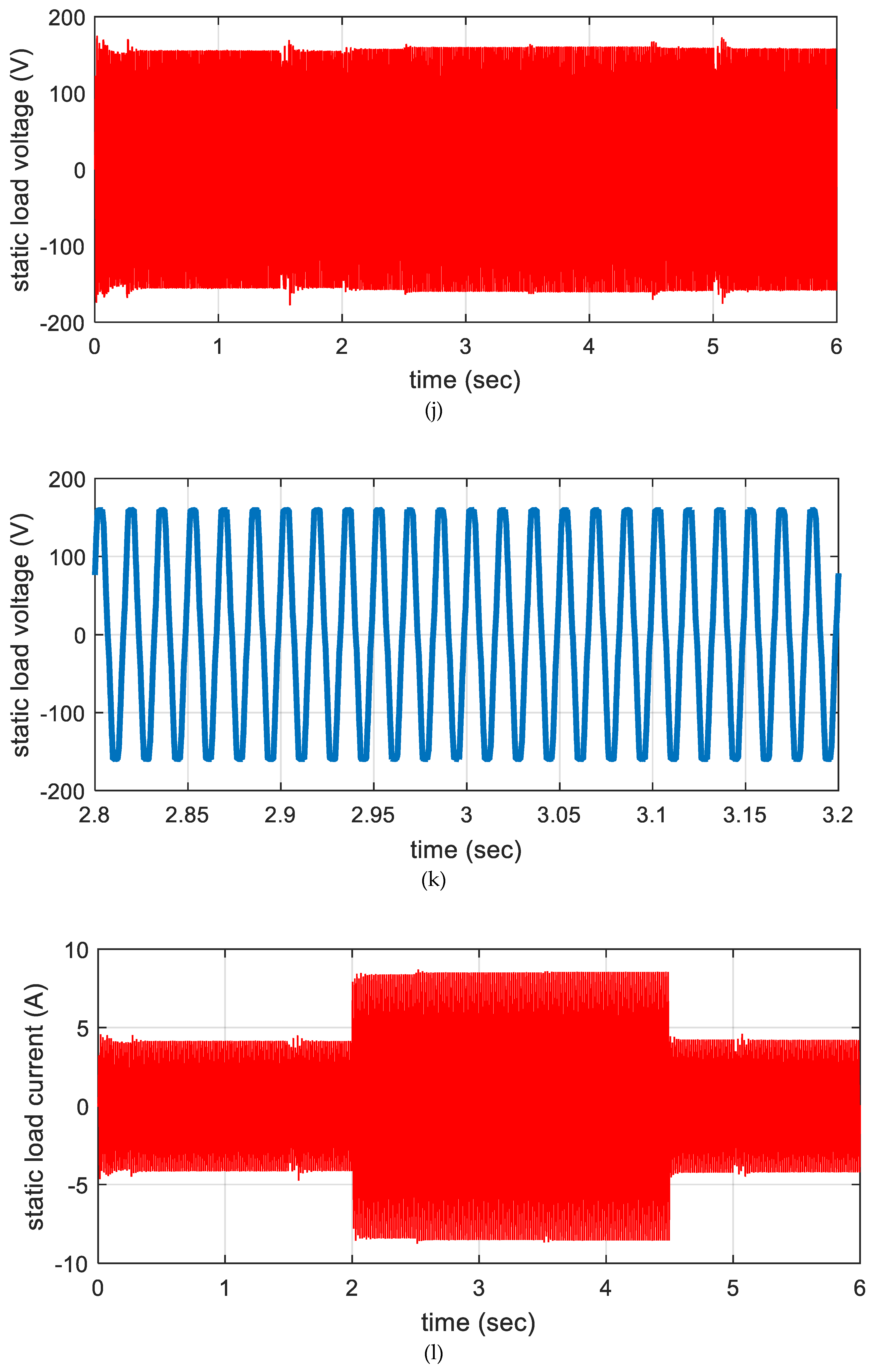
Per unit DC-link actual and desired load voltage and its enlarging are shown in Figure 10h,i, respectively. These figures show that the applied controller tracks well the desired load voltage. It is clear that the response has little overshoot and settling time against all disturbances. This leads also to constant AC output voltage of the inverter as shown in Figure 10j,k.
The FC power increased at a time of 2 s, where the static load current is increased as shown in Figure 10g,l. Also, Figure 10g shows that the fuel cell generated power is more increased in time 2.25 s, where the wind power is decreased. However, the FC power is increased to recover the load power increase. Figure 10g shows also that the FC power decreased when the static load current decreased at time 4.5 s as shown in Figure 10l,m.
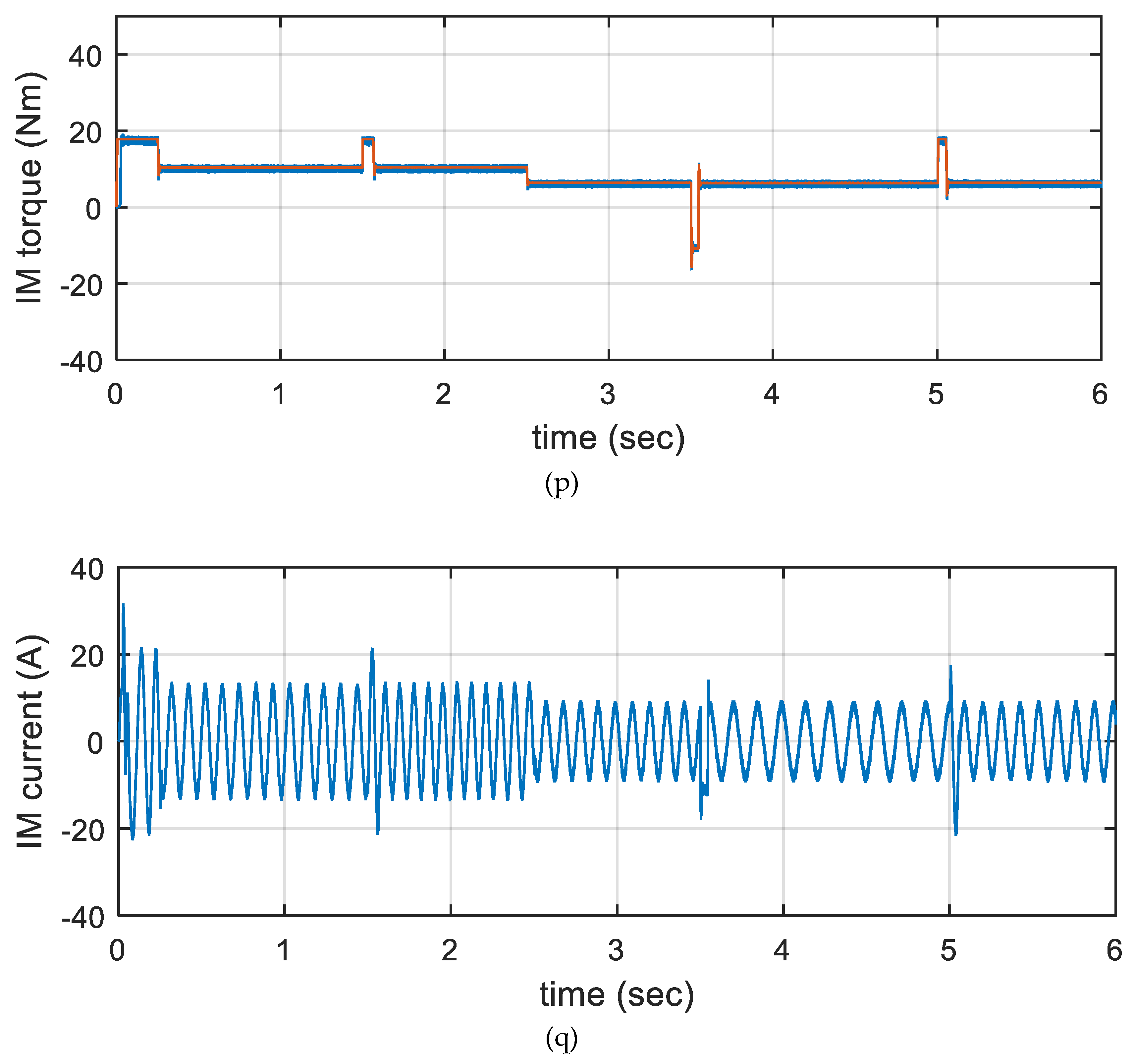
Figure 10n,o show the speed response of the induction motor and its enlarging respectively. From these figures it is seen that the vector controller tracks very well the reference speed of the induction motor. As indicated there is no overshoot and without settling time. Figure 10q shows the stator current of the IM at different speeds and torques. However, the IM load torque changes between 7 and 10 Nm and the IM speed varies between 120 and 200 rad/s, as shown in Figure 10p,n, respectively.
The obtained results are compared with the results obtained in [37], where sliding mode control (SMC) and NARMA-control are applied. The results show that both the proposed optimal control and the robust SMC are able to achieve good voltage and current waveforms parameters and to track the reference DC-link voltage and motor speed with very small overshoot and zero steady state error.
6. Conclusions
This article proposed a microelectrical power grid system composed of an optimal controller design using an MBA algorithm. This studied controlled power system mainly includes hybrid wind/fuel cell generation unit which feeding both dynamic and static loads. These loads are fed by the fuel cell and the wind power generation system. At high values of wind speed wind power acts as the master source that supplies the loads and store hydrogen in the FC via the electrolyzer. Consequently, at low values of the wind speed, the FC acts as a slave that supplies the loads.
IM as a dynamic load, a series R-L load, and as a static load are considered in this paper. The main inverter controller has two nested control loops. The outer loop (voltage loop) uses an optimal PI controller, while the inner loop (current loop) uses hysteresis controller current. On the other hand, the rotor speed of the IM is controlled using optimal vector control.
The proposed microgrid system is simulated using Simulink/MATLAB software and is tested in step variations of wind speed, IM rotor speed, IM torque, and static load current. The results of the simulation show that the proposed generation system success to supply the loads perfectly under all disturbances. It is indicated that the performance of the main inverter controller is excellent, as the load power responses have low overshoot accompanied by small settling time. Also, the proposed optimal controller is able to maintain the DC-link voltage and hence the AC load voltage at its reference value for any variations in wind velocity and the current of the static load and/or dynamic load parameters variations. We also found that the speed of the IM follows its desired value without any settling time or any overshoot. The obtained results show that both the generated wind and fuel cell powers are generated so that the wind power feeds the load power demand, while the fuel cell power compensates for any extra needed power.
Author Contributions
I.E.A., A.M.K., and S.A.Z. conceived, designed the system model, analyzed the results, and wrote the paper.
Funding
This research received no external funding.
Conflicts of Interest
The authors declare no conflict of interest.
Nomenclatures
| Pm | the power output of the wind turbine |
| β | the blade pitch angle (in degrees) |
| ρ | the air density (kg/m3) |
| vw | the wind speed |
| R | the radius of the turbine blade |
| Cp | the performance coefficient of the turbine |
| ωm | the turbine mechanical angular rotor speed |
| Tm | the wind turbine torque |
| Te | the electrical generator electromagnetic torque (N·m), |
| J | the combined inertia of the generator rotor and the wind turbine (kg·m) |
| B | the mechanical viscous friction (N·m·s/rad) |
| rr | the rotor resistance |
| vds, vqs | the stator d- and q-axis voltage components |
| ids, iqs | the stator d- and q-axis current components |
| λdr, λqr | the rotor d- and q-axis flux linkage components |
| Ls, Lr, Lm | the stator inductance, rotor, and mutual inductances |
| ωr | the motor speed, ωs is the motor synchronous speed |
| Tem | the motor electromagnetic torque (N·m) |
| Jm | the inertia of the IM rotor (kg·m) |
| Bm | the viscous friction of the coupling (N·m·s/rad) |
| E | the stack output voltage |
| Eo | the cell open circuit voltage at standard pressure |
| N | the number of cells in stack |
| F | the Faraday’s constant |
| n | the number of transferred electrons in the electrochemical reaction |
| R’ | the universal gas constant |
| T | the operating temperature |
| PH2 | the partial pressure of hydrogen |
| PO2 | the partial pressure of oxygen |
| PH2Oc | the partial pressure of gas water |
| Pstd | the standard pressure |
| Vdrop | the voltage losses |
| i | the output current density |
| in | the internal current density related to internal current losses |
| io | the exchange current density related to activation losses |
| iL | the limiting current density related to concentration losses |
| α | the area specific resistance related to resistive losses |
| (Ig, Vg) | the phase rms current and voltage of the IG |
| (Id, Vd) | the average rectifier output current and voltage |
| d | the duty ratio of the switch |
| (Vfc, Ifc) | the fuel cell output voltage and current |
| Vc | the output voltage, |
| Vi, | the inverter voltage |
| Io | the output current |
| If | the filter current |
| fa, fb, fc | the phase values, |
| F | the space vector of the quantity |
| (L, C) | the filter inductance and capacitance |
| zo | the first shot point, |
| SB, LB | are the problem upper and lower limits |
| γ | the exploration factor |
| Ns | the Shrapnel pieces |
| the shrapnel distance of the exploded mines | |
| F | the fitness function |
| the best location | |
| ts | the simulation time |
| Kp1, Ki1, Kp2, Ki2 | The PI control parameters to be estimated |
| Pw | electrical output power of wind generation system |
| PFC | electrical output power of fuel cell generation system |
| PSL | electrical power needed by the static load |
| PDL | electrical power needed by the dynamic load |
| PNet | the difference between the generated and demanded powers |
References
- REN21. Renewable energy Policy Network for the 21st Century. Global Status Report. 2018. Available online: http://www.ren21.net/gsr_2018_full_report_en (accessed on 20 November 2018).
- Meisen, P.; Loiseau, A. Ocean Energy Technologies for Renewable Energy Generation; Global Energy Network Institute (GENI): New York, NY, USA, 2009. [Google Scholar]
- Pena, R.; Cardenas, R.; Proboste, J.; Clare, J.; Asher, G. Wind–diesel generation using doubly fed induction machines. IEEE Trans. Energy Convers. 2008, 23, 202–214. [Google Scholar] [CrossRef]
- Zhou, W.; Lou, C.; Li, Z.; Lu, L.; Yang, H. Current status of research on optimum sizing of stand-alone hybrid solar-wind power generation systems. Appl. Energy 2010, 87, 380–389. [Google Scholar] [CrossRef]
- Sanyal, S.K. Future of geothermal energy. In Proceedings of the 35th Workshop on Geothermal Reservoir Engineering, Stanford, CA, USA, 1–3 February 2010. [Google Scholar]
- Lazard’s Levelized Cost of Energy Analysis—Version 10. Available online: https://www.lazard.com/media/438038/levelized-cost-of-energy-v100.pdf (accessed on 23 December 2016).
- Nehrir, M.H.; Wang, C.; Strunz, K.; Aki, H.; Ramakumar, R.; Bing, J.; Miao, Z.; Salameh, Z. A Review of Hybrid Renewable/Alternative Energy Systems for Electric Power Generation: Configurations, Control, and Applications. IEEE Trans. Sustain. Energy 2011, 2, 392–403. [Google Scholar] [CrossRef]
- Barnard, M. 7 Factors Show Wind Solar 1st Choices. Available online: https://cleantechnica.com/2016/07/11/7-factors-show-wind-solar-1st-choices/ (accessed on 11 July 2016).
- Zhang, D.; Evangelisti, S.; Lettieri, P.; Papageorgiou, L.G. Economic and environmental scheduling of smart homes with microgrid: DER operation and electrical tasks. Energy Convers. Manag. 2016, 110, 113–124. [Google Scholar] [CrossRef]
- Koohi-Kamali, S.; Rahim, N.A. Coordinated control of smart microgrid during and after islanding operation to prevent under frequency load shedding using energy storage system. Energy Convers. Manag. 2016, 127, 623–646. [Google Scholar] [CrossRef]
- Camblong, H.; Baudoin, S.; Vechiu, I.; Etxeberria, A. Design of a SOFC/GT/SCs hybrid power system to supply a rural isolated microgrid. Energy Convers. Manag. 2016, 117, 12–20. [Google Scholar] [CrossRef]
- Chauhan, A.; Saini, R.P. A review on Integrated Renewable Energy System based power generation for stand-alone applications: Configurations, storage options, sizing methodologies and control. Renew. Sustain. Energy Rev. 2014, 38, 99–120. [Google Scholar] [CrossRef]
- The Energy Foundation Annual Report. Available online: http://www.ef.org/ten-signs-in-2016-that-show-the-clean-energy-economy-is-here-to-stay/ (accessed on 23 December 2016).
- Onar, O.C.; Uzunoglu, M.; Alam, M.S. Dynamic modeling, design and simulation of a wind/fuel cell/ultra-capacitor-based hybrid power generation system. J. Power Sources 2006, 161, 707–722. [Google Scholar] [CrossRef]
- Kassem, A.M.; Hassan, A.A. Performance improvements of a permanent magnet synchronous machine via functional model predictive control. J. Control Sci. Eng. 2012, 2012, 7. [Google Scholar] [CrossRef]
- Ribeiro, P.F.; Johnson, B.K.; Crow, M.L.; Arsoy, A.; Liu, Y. Energy storage systems for advanced power applications. Proc. IEEE 2001, 89, 1744–1756. [Google Scholar] [CrossRef]
- Rastler, D. Electricity Energy Storage Technology Options: A White Paper Primer on Applications, Costs, and Benefits; Technical Report; Electric Power Research Institute (EPRI): Palo Alto, CA, USA, 2010. [Google Scholar]
- Giraud, F.; Salameh, Z.M. Steady-state performance of a grid-connected rooftop hybrid wind–photovoltaic power system with battery storage. IEEE Trans. Energy Convers. 2001, 16, 1–7. [Google Scholar] [CrossRef]
- Yang, H.X.; Lu, L.; Zhou, W. A novel optimization sizing model for hybrid solar–wind power generation system. Solar Energy 2007, 81, 76–84. [Google Scholar] [CrossRef]
- Baziar, A.; Kavousi-Fard, A. Considering uncertainty in the optimal energy management of renewable micro-grids including storage devices. Renew. Energy 2013, 59, 158–166. [Google Scholar] [CrossRef]
- Ahmed, M.; Amin, U.; Aftab, S.; Ahmed, Z. Integration of Renewable Energy Resources in Microgrid. Energy Power Eng. 2015, 7, 12–29. [Google Scholar] [CrossRef]
- Delfino, B.; Fornari, F. Modeling and Control of an Integrated Fuel Cell/Wind Turbine System. In Proceedings of the 2003 IEEE Bologna Power Tech Conference, Bologna, Italy, 23–26 June 2003; p. 6. [Google Scholar] [CrossRef]
- Fathabadi, H. Novel standalone hybrid solar/wind/fuel cell power generation system for remote areas. Solar Energy 2017, 146, 30–43. [Google Scholar] [CrossRef]
- Vidyanandan, K.V.; Senroy, N. Frequency regulation in microgrid using wind—Fuel cell—Diesel generator. In Proceedings of the 2012 IEEE Power and Energy Society General Meeting, San Diego, CA, USA, 22–26 July 2012; pp. 1–8. [Google Scholar] [CrossRef]
- Hussaina, A.; Arifb, S.M.; Aslamc, M. Emerging renewable and sustainable energy technologies: State of the art. Renew. Sustain. Energy Rev. 2017, 71, 12–28. [Google Scholar] [CrossRef]
- Al-falahi, M.D.A.; Jayasinghe, S.D.G.; Enshaei, H. A review on recent size optimization methodologies for standalone solar and wind hybrid renewable energy system. Energy Convers. Manag. 2017, 143, 252–274. [Google Scholar] [CrossRef]
- Zhu, Y.; Tomsovic, K. Development of models for analyzing the load-following performance of micro-turbines and fuel cells. Electr. Power Syst. Res. 2002, 62, 1–11. [Google Scholar] [CrossRef]
- Khan, F.I.; Hawboldt, K.; Iqbal, M.T. Life Cycle Analysis of wind–fuel cell integrated system. Renew. Energy 2005, 30, 157–177. [Google Scholar] [CrossRef]
- Battista, H.D.; Mantz, R.J.; Garelli, F. Power conditioning for a wind/hydrogen energy system. J. Power Sources 2006, 155, 478–486. [Google Scholar] [CrossRef]
- Gorgun, H. Dynamic Modeling of a Proton Exchange Membrane (PEM) Electrolyzer. Int. J. Hydrogen Energy 2006, 31, 29–38. [Google Scholar] [CrossRef]
- Bizon, N. Optimal operation of fuel cell/wind turbine hybrid power system under turbulent wind and variable load. Appl. Energy 2018, 212, 196–209. [Google Scholar] [CrossRef]
- Mendis, N.; Muttaqi, K.M.; Sayeef, S.; Perera, S. Standalone operation of wind turbine-based variable speed generators with maximum power extraction capability. IEEE Trans. Energy Conv. 2012, 27, 822–834. [Google Scholar] [CrossRef]
- MATLAB Math Library User’s Guide’, by the Math Works. Inc. 2015. Available online: https://fenix.tecnico.ulisboa.pt/downloadFile/845043405443232/sl_using_r2015a.pdf (accessed on 1 March 2015).
- Chiu, L.Y.; Diong, B.; Gemmen, R.S. An improved small-signal model of the dynamic behavior of pem fuel cells. IEEE Trans. Ind. Appl. 2004, 40, 970–977. [Google Scholar] [CrossRef]
- Belyaev, P.V.; Mischenko, V.S.; Podberezkin, D.A.; Em, R.A. Simulation Modeling of Proton Exchange Membrane Fuel Cells. In Proceedings of the 2016 Dynamics of Systems, Mechanisms and Machines (Dynamics), Omsk, Russia, 15–17 November 2016; pp. 1–5. [Google Scholar] [CrossRef]
- SharifiAsl, S.M.; Rowshanzamir, S.; Eikani, M.H. Modelling and simulation of the steady-state and dynamic behavior of a PEM fuel cell. Energy 2010, 35, 1633–1646. [Google Scholar] [CrossRef]
- Kassem, A.M. Modeling and Robust Control Design of a Standalone Wind-Based Energy Storage Generation Unit Powering an Induction Motor Variable-Displacement Pressure Compensated Pump. IET Renew. Power Gener. 2016, 10, 275–286. [Google Scholar] [CrossRef]
- Rashid, M. Power Electronics Handbook, 2nd ed.; Elsevier Press: California, CA, USA, 2011. [Google Scholar]
- Ali, E.S.; Abd Elazim, S.M. Mine blast algorithm for environmental economic load dispatch with valve loading effect. Neural Comput. Appl. 2016, 30, 261–270. [Google Scholar] [CrossRef]
- Sadollah, A.; Bahreininejad, A.; Eskandar, H.; Hamdi, M. Mine blast algorithm: A new population based algorithm for solving constrained engineering optimization problems. Appl. Soft Comput. 2013, 13, 2592–2612. [Google Scholar] [CrossRef]
- Majumdar, S.; Mandal, K.; Chakraborty, N. Performance study of mine blast algorithm for automatic voltage regulator tuning. In Proceedings of the 2014 Annual IEEE India conference (INDICON), Pune, India, 11–13 December 2014; pp. 1–6. [Google Scholar] [CrossRef]
- Trzynadlowski, A.M. The Field Orientation Principle in Control of Induction Motors, 1st ed.; Springer: New York, NY, USA, 1994. [Google Scholar]
Figure 1.
The proposed microgrid energy system and its controllers.

Figure 2.
The V–I characteristic of the Proton-Exchange Membrane (PEM) fuel cell at normal environmental conditions.
Figure 2.
The V–I characteristic of the Proton-Exchange Membrane (PEM) fuel cell at normal environmental conditions.

Figure 3.
The boost circuit diagram.

Figure 4.
(a) The power circuit diagram of a 3-φ inverter. (b) The 3-φ inverter space vectors.

Figure 5.
Block diagram of the inverter controller.

Figure 6.
Mine blast algorithm flowchart.

Figure 7.
Boost converter controller block diagram.

Figure 8.
Block diagram of the IM controlled via vector control.

Figure 9.
The flowchart of the power exchange strategy in the proposed autonomous microgrid.

Figure 10.
Simulation results of the proposed system. (a) Wind velocity, (b) IG speed, (c) IG torque, (d) IG stator current, (e) enlarging of (d), (f) FC pressure of H2 and O2, (g) generated power, (h) DC-link voltage (pu), (i) enlarging of (h), (j) static load voltage, (k) enlarging of (j), (l) static load current, (m) enlarging of (l), (n) IM speed, (o) enlarging of (n), (p) IM torque, and (q) IM stator current.


Table 1.
Optimal mine blast algorithm controlling parameters.
| Parameter | Value |
|---|---|
| α | 642.3 |
| Ns | 100 |
| No. of variables | 2 |
| Max_iteration | 100 |
| Final distance | 0.0042351 |
| Number of function evaluations | 10,000 |
© 2019 by the authors. Licensee MDPI, Basel, Switzerland. This article is an open access article distributed under the terms and conditions of the Creative Commons Attribution (CC BY) license (http://creativecommons.org/licenses/by/4.0/).
Share and Cite
MDPI and ACS Style
Atawi, I.E.; Kassem, A.M.; Zaid, S.A. Modeling, Management, and Control of an Autonomous Wind/Fuel Cell Micro-Grid System. Processes 2019, 7, 85. https://doi.org/10.3390/pr7020085
AMA Style
Atawi IE, Kassem AM, Zaid SA. Modeling, Management, and Control of an Autonomous Wind/Fuel Cell Micro-Grid System. Processes. 2019; 7(2):85. https://doi.org/10.3390/pr7020085
Chicago/Turabian StyleAtawi, Ibrahem E., Ahmed M. Kassem, and Sherif A. Zaid. 2019. "Modeling, Management, and Control of an Autonomous Wind/Fuel Cell Micro-Grid System" Processes 7, no. 2: 85. https://doi.org/10.3390/pr7020085
Note that from the first issue of 2016, this journal uses article numbers instead of page numbers. See further details here.