Article

Tamisolve® NxG as an Alternative Non-Toxic Solvent for the Preparation of Porous Poly (Vinylidene Fluoride) Membranes

1
Institute on Membrane Technology (ITM-CNR), Via P. Bucci 17c, 87036 Rende, CS, Italy
2
Center of Excellence in Desalination Technology, King Abdulaziz University, P.O. Box 80200, Jeddah 21589, Saudi Arabia
*
Authors to whom correspondence should be addressed.
Polymers 2021, 13(15), 2579; https://doi.org/10.3390/polym13152579
Submission received: 21 April 2021 / Revised: 14 July 2021 / Accepted: 21 July 2021 / Published: 3 August 2021
(This article belongs to the Section Polymer Applications)

Abstract

:
Tamisolve® NxG, a well-known non-toxic solvent, was used for poly(vinylidene fluoride) (PVDF) membranes preparation via a non-solvent-induced phase separation (NIPS) procedure with water as a coagulation bath. Preliminary investigations, related to the study of the physical/chemical properties of the solvent, the solubility parameters, the gel transition temperature and the viscosity of the polymer–solvent system, confirmed the power of the solvent to solubilize PVDF polymer for membranes preparation. The role of polyvinylpyrrolidone (PVP) and/or poly(ethylene glycol) (PEG), as pore former agents in the dope solution, was studied along with different polymer concentrations (10 wt%, 15 wt% and 18 wt%). The produced membranes were then characterized in terms of morphology, thickness, porosity, contact angle, atomic force microscopy (AFM) and infrared spectroscopy (ATR-FTIR). Pore size measurements, pore size distribution and water permeability (PWP) tests placed the developed membranes in the ultrafiltration (UF) and microfiltration (MF) range. Finally, PVDF membrane performances were investigated in terms of rejection (%) and permeability recovery ratio (PRR) using methylene blue (MB) in water solution to assess their potential application in separation and purification processes.

Graphical Abstract

1. Introduction

On 14 October 2020, the European Commission (EC) divulged a new long-term “Chemicals Strategy for Sustainability” [1], perfectly integrated to the European Green Deal [2], which has been conceived as the guiding principle behind the European chemical industrial innovation. The document relies on sustainability, and in particular on toxic-free environment for protecting people and promoting production innovation towards targeted measures. For achieving this, one of the most successful strategies is to exclude the most harmful chemicals employed for the production with the concomitant boost of substances designed and developed ad hoc to satisfy the safety requirements [3,4,5,6,7]. Food and environmental sectors are primarily involved in the sustainable development and industries are widely adopting eco-friendly technologies to satisfy the balanced growth. Among them, over time, special emphasis has been devoted to membrane technology, which allows to perform separation processes fully respecting the environment integrity and worker health [7,8,9,10,11]. Membranes, both organic and inorganic, are commercially viable and widely used in the most different and disparate sectors, including pharmaceutical and biotechnological fields [8,12,13,14,15]. This is due to the simple preparation methods, uncomplicated processing and good chemical, thermal and mechanical membrane stability. Nevertheless, research is constantly committed to optimize the range of polymeric membranes. In fact, the conventional preparation methods involve the use of organic, harmful compounds; first and foremost, the solvent [16,17,18]. Phase inversion [19,20,21,22], the most versatile and simple technique for membrane fabrication, primarily involves the use of pyrrolidone (NMP), N,N-dimethylformamide (DMF) and N,N-dimethylacetamide (DMAC). However, from May 2020, NMP must not be placed on the European Union market, nor used unless stringent conditions are satisfied [23]. NMP is reprotoxic, provokes serious eye, skin and respiratory irritation. These negative properties led to the addiction of NMP in the Registration, Evaluation, Authorisation and Restriction of Chemicals (REACH) restriction list in 2018 [24]. The restriction came into force in May 2020 placing significant limitation on its use. All the limitations geared towards the correct use of the solvent, are finely described in the guideline released by the European Chemical Agency (ECHA) on July 2019 [23], and, as reported in the document, the general approach referred to NMP can be applied to other aprotic solvents similar to NMP (such as DMF and DMAC), if similar REACH restrictions are introduced for other aprotic solvents. In September 2019, European Commission proposed the addition of DMF to the Annex XVII REACH restriction list with a two-year transitional period for all industrial sectors [25], since it is a hepatotoxic and reprotoxic solvent [26]. The planned date for adopting the Annex XVII amendment is the first quarter of 2021 [25]. The temporary period (two years) before the application of the anticipated restriction is intended to guarantee that stakeholders have sufficient time to comply with the proposed restriction and to warrant adequate communication throughout the supply chain. DMAC was labeled by the European Commission as a Substance of very high concern and registered under REACH due to its reproductive toxicity [27]. Bureau REACH of the Netherlands is preparing an Annex XV restriction dossier on the use of DMAC (Expected date of submission: October 2021) [27].
Consequently, NMP, DMF and DMAC producers and user companies face a high level of investment in order to modernize their production processes, by assuring, for example, exhaustive ventilation, limitation for possible exposure time intervals, well-controlled ovens and enameling machines, in addition to appropriate respiratory equipment. Alternatively, the substitution of the toxic organic solvents with less hazardous chemicals might represents a valuable tool, and offers the possibility to investigate new opportunities for the production sector in line with the sustainability principles. During the phase inversion technique, the solvent plays a major role in determining the structure and performances of the final membrane. It is, in fact, a dominant factor for the thermodynamic behavior and for the solvent-nonsolvent kinetic mass transfer. Table 1 shows the most relevant studies on the use of emergent and greener solvents as well as conventional and toxic solvents for PVDF membranes preparation via phase inversion. This table also evidenced the different types of PVDF used in the literature, the preparation conditions and the membrane configuration achieved (such as flat sheet, hollow fibers and/or nanofibers). Emerging organic solvents were explored for membrane production and the obtained preliminary results have shown as their use can really benefit the innovation sector [28]. Among them, methyl-5-(dimethylamino)-2-methyl-5-oxopentanoate (Polarclean) [29,30,31,32,33,34] Cyrene™ [35,36,37,38], dimethyl isosorbide [39], triethyl phosphate [40,41,42,43,44], diethylene glycol monoethyl ether acetate [45], glycerol triacetate (triacetin) [46], acetyl tributyl citrate [47], triethylene glycol diacetate [48], acetyl triethyl citrate [47], triethyl citrate [47] were proposed as non-toxic solvents for poly(vinylidene fluoride) (PVDF) membrane production through phase inversion. Carner et al. [38] reported the use of several greener solvents, including ethyl acetate, 2-methyltetrahydrofuran (2-methylTHF) and Cyrene™ for the preparation of polymer inclusion membranes. In particular, ethyl acetate was chosen as a solvent for dissolving poly(vinylidene fluoride-co-hexafluoropropylene) (PVDF-HFP), 2-methylTHF for poly(vinyl chloride) and Cyrene™ for cellulose triacetate. Park et al. [28] described the fabrication of thin film composite (TFC) membranes by employing naturally occurring components, such as recycled poly(ethylene terephthalate) which was used as a support, priamine and tannic acid as monomers, and p-cymene and water as solvents. The obtained membranes exhibited promising performance for applications in organic solvent nanofiltration, due to the long-term stability and permeance in six different solvents. Other alternative solvents such as N,N -dimethyl lactamide (AGNIQUE AMD 3L) [49] were also proposed for PES membranes. In order to overcome the issue related to the use of conventional organic solvents, including their recovery, recycle and/or disposal, Razaliet al. [50] and Paseta et al. [51] described an innovative procedure for obtaining TFC membranes in the total absence of solvent. In fact, polyamide TFC membranes for nanofiltration and reverse osmosis applications were prepared by interfacial polimerization in the vapor phase. Besides phase inversion, membranes in the hollow fiber configuration, can be fabricated also by melt-spinning and stretching without the need for solvents, as recently demonstrated by Ji et al. in 2020 [52].
PVDF represents one of the most required membrane materials, and this is because it offers outstanding properties in terms of thermal, chemical and mechanical stability compared to other commercially available polymers [53,54]. Even though the research on new (preferably bio-based) materials is constantly objective of interest for the achievement of a fully “green” production process, PVDF still remains one of the major versatile thermoplastics applied for ultrafiltration (UF) and microfiltration (MF) separation purposes [53]. Tamisolve® NxG is an organic, polar aprotic solvent, marked by biodegradability and the absence of reprotoxicity [55]. For membrane preparation, Tamisolve® NxG appears as a suitable candidate for the replacement of commonly used toxic solvents in membrane preparation, since it is fully miscible with water and allows the dissolution of semicrystalline polymers due to its high boiling point (241 °C) [56]. Doyen cited Tamisolve® NxG as NMP alternative for making film-supported membranes by using both amorphous and semicrystalline polymers [57]. Bu described methods for manufacturing polyimides films with Tamisolve® NxG instead of NMP [58]. Table 1 summarizes the studies reported in literature for PVDF membranes prepared with more sustainable solvents (including all the works with Tamisolve® NxG) and with traditional solvents. Marino et al. employed Tamisolve® NxG for the first time for preparing PVDF-HFP membranes via vapor induced phase separation (VIPS) tested in direct contact membrane distillation; experiments conducted at different temperatures highlighted performance similar to those of commercially available membranes in polypropylene [56]. Crystallization experiments were investigated with the same PVDF-HFP membranes using Tamisolve® NxG as a solvent via non-solvent phase separation (NIPS) by Saidi et al. [59]. Tamisolve® NxG was also selected for producing a support nanofiltration (NF) membrane for crosslinked PVDF [60] and for NF membranes preparation via spray-modified non-solvent induced phase separation (s-NIPS) [61]. Another important study with Tamisolve® NxG was conducted by Bagnato et al. [62]. They prepared more sustainable PEEK-WC catalytic membranes doped with Ruthenium (Ru) via the VIPS/NIPS technique for the application in the hydrogenation reaction of bio-oil model compounds. In this work, PVDF flat sheet membranes were prepared via Non-solvent-Induced Phase Separation (NIPS) by using Tamisolve® NxG as solvent and water as non-solvent. Polyvinylpyrrolidone (PVP) e polyethylene glycol (PEG) were chosen as pore former additives and the influence of their concentration was studied. The obtained membranes were characterized in terms of morphology, pore size, porosity, thickness, contact angle, AFM and ATFR-IR. Filtration tests were also carried out in terms of pure water permeability (PWP), methylene blue (MB) rejection and permeability recovery ratio (PRR) for potential MF/UF applications in separation and purification processes.

2. Materials and Methods

2.1. Materials

The PVDF Solef®6010 (Solvay Specialty Polymers, Bollate, Italy; Molecular weight Mw = 322 kg/mol) homopolymer was kindly provided by Solvay Specialty Polymers (Bollate, Italy) while Tamisolve® NxG solvent was kindly supplied by Taminco (Gent, Belgium), a subsidiary of Eastman Chemical Company and used without any further purification. Polyethylene glycol-PEG200- (Mw = 0.2 kg/mol) and Methylene Blue (MB) hydrate were purchased from Sigma Aldrich (Milan, Italy). Polyvinylpyrrolidone (PVP K17) (Mw = 9 kg/mol) was purchased by BASF (Lud-wigshafen, Germany). The PVDF polymer and PVPK17 were desiccated under vacuum at 40 °C for 12 h before use. Distillate water was used at 15 °C for the coagulation bath and at 60 °C for washing treatment.

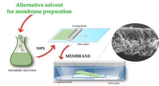
2.2. Membrane Preparation

The dope solutions were prepared by adding the correct amounts of polymer powder into Tamisolve® NxG solvent and varying the quantities of additives (PVP K17 at 5 wt% and PEG200 at 10, 15, 20 and 40 wt%). The concentration of PVDF 6010 polymer was also modified from 10 wt% to 18 wt%. The solutions were maintained under stirring at 80 °C for two hours, until became homogeneous. Subsequently, the dope solutions were kept at same temperature without stirring for 6 h (degassing time) for removing possible air bubbles. The temperature of the solutions at high content of polymer (18 wt%) and additives (PEG200: 40 wt%) was fixed at 120 °C. The homogenous solution was cast via the NIPS technique by making use of a glass plate and a manual casting knife with reservoir (Elcometer 3700/1 Doctor Blade, Germany). The knife gap was 350 µm and humidity room was 40 Rh%. The nascent membrane was directly immersed in a coagulation bath of water at 15 °C. The membranes were also washed three times in hot water (60 °C) and then dried in an oven overnight at 40 °C. The casting solution conditions of the PVDF 6010 membranes preparation are listed in Table 2.

2.3. Membrane Characterization

2.3.1. Phase Diagram

In order to determine the sol-gel transition temperature for the PVDF 6010/Tamisolve® NxG system, the tube tilting method was utilized. For each concentration (10 wt%, 15 wt%, 20 wt% and 25 wt%), the transparent solutions were prepared at 80 °C. Then, the temperature was decreased by 5 °C every one hour stepwise. The solution was extracted from the oil bath for a time lag of 10 s every time the temperature changed until the gel phase was achieved.

2.3.2. Scanning Electron Microscopy (SEM)

The morphology was determined by Scanning Electron Microscopy (SEM; Zeiss EVO, MA100, Assing, Italy). The cross-section samples were fractured in liquid nitrogen and fitted vertically on a sample holder. All samples (top, bottom, cross sections) were coated with gold by sputter machine (Quorum Q 150R S).

2.3.3. Viscosity

The viscosity of solutions was measured by using a rotational rheometer (Brookfield, Synchro-Lectric viscometer model: LV). The temperature used was 80 °C.

2.3.4. Pore Size and Pore Size Distribution

The pore size and pore distribution measurements were carried out by using the wet-up/dry-up method with a PMI Capillary Flow Porometer (CFP1500 AEXL, Porous Materials Inc., Ithaca, NY, USA) connected to the software Capwin. Each membrane sample was soaked in the wetting fluorinate liquid Fluorinert FC-40 for 5 h. Two measurements were carried out for each membrane and average and the standard deviation were calculated.

2.3.5. Thickness, Porosity and Contact Angle

Membrane thickness was detected by a digital micrometer (Carl Mahr, Göttingen Germany) and registered in eight regions of each membrane. Porosity values of membranes were calculated during 24 h, using the gravimetric method and considering the weight of membrane samples before and after the immersion in Kerosene. The porosity was determinate by following equation:
ε ( % ) = { ( Ww Wd )   / ρ k ( Ww Wd ) / ρ k + ( Wd ρ P ) } × 100
This equation includes the information about the weight of the wet (Ww) and dry membrane (Wd), the density of Kerosene (ρk = 0.81 g/cm3) and the density of PVDF polymer (ρP = 1.78 g/cm3). The measure was performed on three different pieces of the same membrane and the average percentage and standard deviation were calculated.
The wettability of the membranes was analyzed by means of a CAM 200 contact angle instrument (KSV Instruments LTD, Helsinki, Finland) using ultrapure water droplets (5 µL). For each membrane, five measurements were acquired and averages and standard deviations were calculated.

2.3.6. Atomic Force Microscopy (AFM)

The surface roughness of the membranes was investigated by using atomic force microscopy (AFM) from Nanoscope IIIA (Digital Instruments, VEECO Metrology Group). The AFM pictures were detected in tapping mode (velocity: 2.54 Hz) with the dimension of 5 µm × 5 µm and the roughness parameters were quantified in term of root-mean-square roughness (Rq) and mean roughness (Ra). One hundred values were taken in different parts of each membrane and the average and error have been reported.

2.3.7. Attenuated Total Reflectance Fourier Transform Infrared Spectroscopy (ATR-FTIR)

The different phases (α, β, γ) of PVDF were analyzed by ATR-FTIR spectra at a resolution of 4 cm1. The measurements were carried out in different points of the sample area at the same pressure with a micrometer torque (UATR crystal Diamond/ZnSe—Spectrum One System by Perkin Elmer Instruments).

2.3.8. Water Permeability Test and Filtration Experiments

The water permeability (PWP) of the membranes was evaluated using a cross-flow cell system (DeltaES.r.l., Rende, Italy) connected to the feed by a gear pump (Tuthill Pump Co., California). Two samples for each membrane were investigated and the average and standard deviation were calculated. The values were measured using the following equation:
PWP = Q ( A   ·   t   ·   Δ P )
where Q is the permeate volume (L), A is the membrane area (m2), t is the time (h), and p is the pressure (bar). The area of the membrane was 8 cm2, the measurements were evaluated after a stabilization time of 40 min (time required to reach the steady state condition) at a transmembrane pressure of 2 bar and at room temperature (25 °C). After the stabilization period, the water permeate was collected within 60 s after applying three different transmembrane pressures (the stabilization period of one to another was about 10 min).
The filtration experiments were performed with the same cross-flow filtration set-up used for water permeability tests at 25 °C under pressures ranging from 2 to 3 bar depending on the membrane water permeability. An aqueous methylene blue (MB) solution (10 mg/L) was used as a feed and filtered through the membranes. Membrane samples were conditioned in the MB solution overnight before being tested. The rejection (R) of the membranes towards MB was calculated by the Equation (3):
R % = ( 1 Cp Cf   ) × 100
where Cp is the concentration of MB in the feed and Cp is the concentration of MB in the permeate. The concentration of MB was determined via spectrophotometer (ShimadzuUV-160A, Kyoto, Japan) at a wavelength of 664 nm. The flux of MB was estimated by Equation (2). After the rejection analysis of MB, the membrane samples were washed with water for 1 h and the pure water flux of these cleaned membranes was re-measured. Then, the permeability recovery ratio (PRR) was also calculated applying Equation (4):
PRR   ( % ) = (   Pwp 2 Pwp 1   ) ·   100
where Pwp2 is the water permeability of the cleaned membrane and the Pwp1 is the initial pure water permeability.

3. Results and Discussion

3.1. Phase Separation of PVDF /Tamisolve® NxG Systems

In order to investigate the thermodynamics of membrane preparations and the interaction between polymer, solvent and non-solvent, Hansen solubility parameters (HSP) were considered. HSP can be an important tool to discuss the influence of different components during phase inversion and on membrane structure and/or performance. According to Hansen theory, the three-dimensional solubility parameters (HSP) in terms of dispersion (δd), polar (δp), and hydrogen bonds (δh) for the solvent Tamisolve® NxG are 17.8 MPa ½, 8.2 MPa ½, 5.9 MPa ½, respectively. The total solubility parameter of the solvent is δT: 20.3 MPa ½ [39] that is very close to the one of PVDF (δT: 23.2 MPa ½) [71] and very far to the one of water (δT: 47.8 MPa ½) being the non-solvent of the system. Figure 1 shows the sol-gel transition temperature of PVDF/Tamisolve® NxG system as a function of polymer concentration (10 wt%, 15 wt%, 20 wt% and 25 wt%). The sol-gel transition is the temperature at which the solution becomes gel and the solution flow is not observed. The results confirmed that the sol-gel transition temperature increased as the PVDF concentration increased. This outcome is in accordance with literature data which indicate the necessity to use higher temperatures to keep polymer–solvent dope solutions in a homogeneous state when the polymer concentration increases.

3.2. Morphology and Viscosity

Membrane morphology can be influenced by the polymer/solvent/non-solvent system during the phase inversion process, by the viscosity of the dope solution and also by the operative conditions. Tamisolve® NxG represents the next-generation of polar aprotic solvents [72] with a high safety profile and solubility parameters comparable to traditional solvents such as NMP, DMF, DMA, indicating the possibility to produce membranes by the NIPS procedure. The different structures of PVDF membranes can be obtained by varying the concentration of polymer (10 wt%, 15 wt% and 18 wt%) and additives (PVPK17 and PEG200) in the dope solutions.
Figure 2 shows the morphology of the top, bottom and cross-section of the membranes prepared at 15 wt% of PVDF polymer from the polymer–solvent system (MN1) and from the polymer-additive-solvent system (MN2, MN3 and MN4) where just one of the two additives (PVP K17 and PEG 200) was used.
The top surface of the membranes (Figure 2a,e) was characterized by a dense and compact layer, in agreement to what is generally observed for the membranes prepared by the NIPS procedure [34,40].
The formation of this top layer is the result of the fast de-mixing rate of the cast dope solution which enters in contact with the water coagulation bath. At the interface between the casting solution and the coagulation bath, the increase in polymer concentration leads to a decrease in the surface porosity and to the formation of the dense top structure [73]. The top surface of the MN3 membrane (Figure 2i) is characterized by the presence of pores owing to the use of PEG200 (20 wt%) employed as a pore forming agent in the casting solution. The bottom surface of MN1 membranes (Figure 2b) showed, on the contrary, a porous and flatted structure. The reason lies in the fact that the solvent/non-solvent exchange is slowed down by the formation of the dense top layer and the creation of a more porous structure is hence favored.
The cross-section of MN1 (Figure 2c,d) is characterized by a dense skin layer and a spongy sublayer with some visible spherulitic structures whose formation can be the result of a polymer crystallization effect as reported by Zhang et al. [74], Chuang et al. [75] and Ali et al. [76]. They have pointed out that the formation of the sublayer is strongly influenced by the precipitation rate of the top layer that can cause a reduction of solvent outflow rate towards the coagulation bath retarding the de-mixing process. This is in accordance with the low time of the membrane formation in the coagulation bath (~8 min for MN1) as reported in Table 2. A delayed de-mixing is generally responsible for the formation of membranes characterized by a dense surface with a porous sublayer [77]. The addition of PVPK17 and PEG 200 in the dope solution played an important role in the de-mixing rate during the phase inversion and affected the final morphology of the membranes. These additives are employed to improve the membrane pore dimension and porosity thanks to their affinity with the water contained in the coagulation bath. Their hydrophilic nature can, in fact, induce a much faster de-mixing leading to the formation of finger-like macro-void structures as showed in the cross-sections of the MN2 (Figure 2g,h), MN3 (Figure 2k,l) and MN4 (Figure 2o,p) membranes. For MN2, the presence of only PVP at 5 wt% resulted in a membrane characterized by spherulites along the cross-section (Figure 2g) and by a dense top surface (Figure 2e). Besides that, the bottom surface of M2 membrane (Figure 2f) is totally dense respect to the bottom surface of MN1 (Figure 2b) when only PVDF and Tamisolve® NxG were used. This could be ascribed to the properties of the PVPK17, that, as well reported in the literature [66], tends to intertwine with PVDF chains due to its high affinity for the polymer. In this view, the solvent outflow during the solidification phase of the polymeric membrane can be responsible of the formation of a dense bottom surface [78,79]. However, the more open structures were evidenced when PEG 200 was added to the dope solution at 20 wt% (MN3 membrane). The presence of PEG 200 resulted in a finger-like structure with a sponge-like sublayer (Figure 2k,l) and a porous bottom side (Figure 2j). This can be attributed to the role that PEG 200 plays in the mechanism of phase inversion. Wang et al. [80] observed that PEG 200 (from 0 wt% to 20 wt% of content) promoted the transit from a delayed de-mixing (sponge like structure for MN1) to instantaneous de-mixing (finger-like structure for MN3). On the other hand, the presence of additives can increase the viscosity of the dope solution (Table 3) which can limit the solvent/non-solvent exchange rate and can promote the formation of more open structures. The viscosity increased from 375.5 ± 1 cP for MN1 (without additives) to 815.2 ± 1 cP for MN2 (with PVP K17) and to 787.3 ± 1 1 cP for MN3 (with PEG200).
The effect of PEG 200 was also evaluated by keeping constant the concentration of the polymer (15 wt%) and of the additive PVP (5 wt%). In this case, the PEG 200 concentration was varied from 10 to 40 wt % (membranes MN5- MN8) and their morphology is reported in Figure 3.
It was clearly observed that all membranes showed a dense top layer (Figure 3a,e,i,o) and a porous bottom layer (Figure 3b,f,j,n). No relevant differences were found for the cross-section structures from 10 wt% (dynamic viscosity of 951 ± 1 cP) to 20 wt% (dynamic viscosity of 1546 ± 1 cP) of PEG 200. The main difference is observed for the membrane prepared with the highest concentration of PEG 200 (MN8) whose bottom layer (Figure 3n) appeared less porous and more compact. In this case, the higher dope solution viscosity could be responsible for a slower polymer precipitation with a reduction of solvent and additives diffusion during the phase inversion.
The effects of higher and lower polymer concentrations (18 wt% and 10 wt%) on membranes morphology were also evaluated while keeping a constant concentration of PEG 200 (20 wt%) and varying the concentration of PVP (0 and 5 wt%) (membranes MN9-MN12).
In Figure 4, the structure of the MN9 and MN10 membranes, prepared, respectively, using 18 wt% of PVDF without and with PVP, is reported. Both membranes exhibited dense surfaces (Figure 4a,e and Figure 5a,e). MN9 clearly presented a finger-like structure in the upper part of the membrane similar to the one observed for the analogue membrane M3 prepared with 15 wt% of polymer. The sublayer of the membrane is characterized by a spherulitic structure. However, the addition of PEG 200 (MN10) resulted in a fading of the fingers and in the suppression of the spherulitic structure in favor of a more compact morphology. This can be related to the increase in viscosity as a consequence of the PVP addition which could have hindered the mobility of PVDF 6010 polymer chains [56].
The morphology of MN11 and MN12 membranes, prepared at lower polymer content (10 wt%), is reported in Figure 5. It is possible to observe that the bottom of both membranes showed a porous surface with MN11 surface (Figure 5b) more open than MN12 (Figure 5f). The cross-section for MN11 exhibited a more porous structure, with the presence of macro-voids (Figure 5c,d). Generally, at low content of polymer, the diffusion of the non-solvent into the system (water in this case) is high, ensuring the formation of very porous structures [81]. This was also confirmed by the values of dynamic viscosity (675 ± 1 cP) for MN11 membrane reported in Table 3. By adding the PVP K17 in the same solution (MN12), the macro-voids became longer and the top layer appeared clearly finger-like with a sponge-like structure on the sublayer (Figure 5g,h).

3.3. Pore Size and Pore Size Distribution

The pore size values and pore distribution of the PVDF 6010 membranes are investigated and reported in Figure 6a–d. It is possible to observe in Figure 6a that the pore dimension is between the ultrafiltration (UF) and microfiltration (MF) range, from 0.03 µm to 0.17 µm. The differences found agree with SEM analysis and depend on the types and content of additives and on polymer concentration. For MN1, at 15 wt% of polymer concentration and without the presence of additives, the pore size was 0.05 µm. No significant difference was observed when the PVP K17 (5 wt%) was added in the dope solution (0.06 µm for MN2). These values are in agreement with the results of pore size reported in literature for PVDF membranes prepared via NIPS procedure [39,82,83] and with the pore distribution reported in Figure 6b. An important increase in pore size is observed with the addition of PEG 200 (20 wt% for MN3) due to its ability to act as a pore former, while for higher concentrations (40 wt%) the pore size decreased (0.09 µm for MN4). As reported in Figure 6b, the pore distribution for MN4 is very narrow with a 90% of pores at 0.09 µm. When both additives were used for membranes preparation, the increase in PEG 200 concentration (10 wt%, 15 wt%, 20 wt%) led to an increase of the pores dimension as visible for MN5, MN6 and MN7 which showed a pore size of 0.03 µm, 0.04 µm and 0.07 µm, respectively. However, the further increase of PEG 200 to 40 wt% (MN8) led to a slight decrease in pore size (0.05 μm) as also occurred in MN4 membrane. As argued in SEM discussion, the increase in the solution viscosity, probably delayed the formation of the membrane leading to a more compact structure. This result was also confirmed by the pore size distribution, shown in Figure 6c, that was not very uniform for MN5 and MN8 membranes. The MN9 and MN10 membranes, prepared with a higher concentration of polymer (18 wt%) and in the presence of PEG 200 (20 wt%) and PVP K17 (only for MN10), exhibited values of pore size of 0.06 µm and 0.03 µm, respectively. In this case, in agreement with SEM pictures and pore size distribution reported in Figure 6d, the presence of PVP resulted in a more dense structure with a reduced pore size as a consequence of a solution viscosity increase. By decreasing the polymer content (10 wt%), the pore size increased, with a value of 0.17 µm for MN11 and 0.06 µm for MN12 with a narrow pore distribution (Figure 6d), in comparison to the membranes prepared at higher polymer concentrations (MN9 and MN10). In this case, the non-solvent water can penetrate into the casting film with a considerable velocity and can diffuse into the system ensuring the formation of larger pores.

3.4. Thickness, Porosity and Contact Angle

Thickness, porosity and contact angle results are summarized in Table 4. The thickness of PVDF membranes prepared via NIPS using Tamisolve® NxG as a solvent, ranged from 90 ± 1 µm to 138 ± 1 µm depending on the dope solution composition. For MN1 membrane at 15 wt% of PVDF, the thickness was 100 ± 1 µm which slightly increased to 125 ± 1 µm for MN2 with the presence of PVP K17.
The MN3 membrane, containing the 20 wt% of PEG 200, exhibited a thickness of 104 ± 1 µm and when its concentration increased from 20 wt% to 40 wt% (MN4) the thickness slightly increased with a value of 107 ± 1 µm. The thickness for the membranes containing both PVP and PEG 200 (MN5, MN6, MN7 and MN8) ranged from 109 ± 1 µm to 123 ± 1 µm. It was also observed that the higher polymer concentration (18 wt%) led to an increase in the thickness with values of 133 ± 1 µm for MN9 and 138 ± 1 for MN10. On the contrary, the thickness decreased at lower polymer concentration (10 wt%) for MN11 and MN12 (90 ± 1 µm and 96 ± 1 µm, respectively). These results are consistent with the porosity values measured. The porosity is between 71% and 89% for all the membranes prepared. As expected, the porosity decreased with the increase of polymer concentration as a consequence of the denser nature of the membranes. The same results were observed for the membranes at high PEG 200 content. By measuring the wettability of the prepared membranes, the MN1 membrane, not containing any additive, was the more hydrophobic membrane with a CA of 91°. The lower values of contact angle, observed for the other membranes, can be related to the addition of the two hydrophilic additives PVP K17 and PEG 200 into the casting solution. The contact angle of these membranes ranged from 77 ± 1° to 88 ± 1° for top side and from 78 ± 1° to 110 ± 1° for the bottom side.
The different values of CA for the bottom surfaces might be related to the different roughness of this side (more porous as shown in SEM pictures) respect to the top layer. According to the Cassie–Baxter model, in fact, porous surfaces generally show higher apparent CA values due to their ability to entrap air pockets within their pores [84].
MN1 membrane presented the highest value of CA (91°) in line with the hydrophobic nature of the polymer. The lower values observed for the top layers of the other membranes can be the consequence of the presence of the hydrophilic pore formers (PVP and PEG) which could not be totally washed away from the membranes [44].

3.5. AFM Analysis

The AFM three-dimensional structures and surface parameters, in terms of root-mean-square roughness (Rq) and mean roughness (Ra), are reported in Figure 7 and Figure 8, respectively. The AFM analysis were conducted for the MN1 membrane without the presence of additives and for the MN2, MN3 and MN7 membranes prepared at different concentrations of additives as shown in Table 2. As already observed in the SEM pictures (Figure 2), MN1 and MN2 membranes showed a smooth surface as confirmed by the lower values of average roughness. The Rq value was, in fact, 16 ± 3 nm for both MN1 and MN2 membranes while the Ra values were 12 ± 2 nm and 13 ± 3 nm for MN1 MN2 membranes, respectively. The AFM pictures for MN3 membranes, prepared with 20 wt% of PEG200, confirmed the presence of a porous structure on the top surface in accordance with the SEM analysis with slightly higher values of roughness (Rq = 22 ± 7 nm, Ra = 18 ± 7 nm). The surface roughness parameters were much higher for the MN7 membrane (Rq: 99 ± 48 nm, Ra: 79 ± 40 nm) probably due to the addition of both PVPK17 and PEG200 in the dope solution which promoted the formation of a more porous structure (as shown in porosity and pore size data).

3.6. ATR-FTIR Spectra

To verify the crystalline polymorphism of PVDF membranes, the infrared spectroscopy (ATR-FTIR) analysis was carried out and the spectra are reported in Figure 9.
As reported in the literature [85,86,87], PVDF polymer has five crystalline polymorphs: α (phase II), β (phase I), γ (phase III), δ and ε. The α phase represents a non-polar form, kinetically more stable and dominant in the presence of non-polar solvents, whereas the β-phase is a highly polar form, which is thermodynamically more stable and can be induced by the presence of additives and/or operation conditions. The polar form can be individuated for the γ-phase, but weaker than the β phase due to the presence of a gauche bond in every fourth repeating C–C units [88,89]. The ATR-FTIR peaks identified at 1383, 1209, 1182, 976, 797 and 762 cm−1 correspond to the α phase, while the peaks at 1404, 1069, 874 and 840 cm−1 confirm the presence of the β phase. The 840 cm−1 peak in the MN1 spectrum is common for both β- and γ-phases, as reported in literature [90,91] and it disappeared in the spectrum of the MN8 membrane. Besides polymer properties, the final polymorphism of PVDF membranes can be influenced by the polarity of the solvent employed for its solubilization, by the type of additives present in the dope solution and by the temperature that can influence the crystallization time of PVDF. Generally, PVDF crystals can reorganize following the most stable phase at the employed temperatures. The β phase of PVDF is difficult to be obtained at high temperatures since the polymer chains are more freely to move.
The predominance of the α phase for both membranes indicate that kinetic factors play a major role in membranes in the PVDF crystallization process.

3.7. Filtration Properties

3.7.1. Water Permeability Results

The water permeability (PWP) values are reported in Figure 10. For the membrane prepared at 15 wt% of PVDF polymer via NIPS without additives (MN1) and with the presence of PVP K17 (MN2), PWP resulted much lower than the membranes prepared with PEG 200. For MN1, no PWP was detected (until 4 bar). This result is in agreement with the literature data for the same type of membranes [39,92]. There is probably no water passage through the membrane due to the presence of a thick dense layer. The values of PWP increased from 22 L/m2 h bar for MN2 prepared with 5 wt% of PVP K17 to 258 L/m2 h bar for MN3 at 20 wt% of PEG 200. The PWP of all membranes also increased as the PEG concentration increased from 0 wt% (MN1) to 20 wt% (PWP ranged between 51 L/m2 h bar and 364 L/m2 h bar for MN3, MN7, MN9 and MN11) and declined sharply as the concentration rose from 20 wt% to 40 wt% (60 L/m2 h bar for MN4 and 28 L/m2 h bar for MN8). This effect can be attributed to the role that PEG plays on the viscosity of the solution and on the hydrophilicity of the membrane. The hydrophilic PEG (until 20 wt%) encourages the instantaneous de-mixing and promotes the formation of finger-like macro-void structures, leading to the enhancement of water permeability of the membrane. However, when the concentration of PEG increases until 40 wt%, the water permeability of the membranes decreases due to the lower porosity and pore size. The PWP of membranes containing both PEG and PVP, at different concentrations of polymer (MN5, MN6, MN7, MN8 at 15 wt%, MN10 at 18 wt% and MN12 at 10 wt%), decreases in accordance to their lower pore size. The PWP of the membrane at 18 wt% of PVDF (MN10) was not detected respect to the corresponding MN9 membrane obtained without the presence of PVP K17 (51 L/m2 h bar); while the PWP of the membrane at 10 wt% of PVDF (MN12) showed a PWP of 88 L/m2 h bar with respect to MN11 (364 L/m2 h bar).

3.7.2. Filtration Results

In order to demonstrate the applicability of prepared PVDF membranes in MF/UF processes, MN3 MN7 and MN12 membranes were tested in filtration experiments using MB dye. The performance of the membranes was investigated in terms of rejection (%) and MB permeability (MBPW), as reported in Figure 11.
The MB rejection for the MN3 was about 56% with a MB permeability of 19 L/m2 h bar. The low rejection of this membrane is related to the high pore size of the membrane (about 0.15 μm), in the MF range. The rejection of MN7 was higher (about 86%) with a MBPW of 29 L/m2 h bar, while the rejection for the MN12 was 79% with a MBPW of 23 L/m2 h bar. The close values of MB rejection and MBPW for these two membranes can be also related to their very similar pore size (about 0.06 μm).
The permeability recovery ratio (PRR) for the PVDF membranes is shown in Table 5. In the same table, the performance of PVDF membranes reported in the literature and prepared with other greener or traditional toxic solvents are also shown. The PRR value for the membranes evaluated in this work ranged from 81 to 94%. The results are comparable with the ones obtained by Ngang et al. [93] for PVDF membranes formed by using DMAc (PRR: 94%). Other greener solvents were used for PVDF membranes and the MB rejection was investigated. In particular, Alyarnezhad et al. [44] prepared PVDF membranes from 13 wt% polymer by using TEP as a green solvent (Table 5) obtaining 53% of rejection. A similar result, in terms of rejection (51%), was obtained by Benhabiles et al. [43] that produced a membrane of blended PVDF/PMMA. In the case of toxic solvents (DMAc, DMF and NMP) the rejection of MB for a series of membranes was about 40–45 wt% [94,95,96] with a very variable water permeability.

4. Conclusions

This work demonstrated the possibility of employing Tamisolve® NxG as a non-toxic solvent for the preparation of PVDF 6010 membranes. Two different additives (PVP K17 and PEG 200), as well as different polymer concentrations (10 wt%, 15 wt%, 18 wt%) were investigated. The effect of high content of PEG 200 (from 10 wt% to 40 wt%) was also studied. The results confirmed the possibility to obtain asymmetric structures with different morphology (sponge or finger-like macro-void) with a wide range of pore size. Thickness, porosity, contact angle and water permeability were also influenced by dope solution composition. The MN1 membrane prepared at 15 wt% of PVDF polymer without additives in Tamisolve® NxG exhibited a spherulitic morphology with a pore size in the range of UF. Same pore size was also obtained for the MN2 membrane with PVP K17. The influence of PEG 200 without the presence of PVP K17 was also studied. PEG 200 at 20 wt% resulted to be the best concentration in the casting solution for its hydrophilic characters and for the high permeability of the membranes. Polymer concentration played also a crucial role in membrane morphology. Low polymer concentrations (10 wt%), for instance, resulted in a membrane structure characterized by macro-voids, large pore size and high permeability. The produced PVDF membranes showed a porosity ranging from 71% to 89% with a contact angle ranging from 75° to 91° for the top surface and from 78° to 117° for the bottom surface. The infrared spectroscopy (ATR-FTIR) confirmed the presence of both α and β phases of PVDF. The results of PWP as well as the filtration tests in terms of MB rejection and PRR confirm the potential use of these membranes in MF and UF applications for separation and purification processes. This work can also represent a good advance in the redesign of homopolymer PVDF membranes for their production using greener and more sustainable solvents.

Author Contributions

Conceptualization, A.F. and T.M.; methodology, A.F., T.M. and F.R.; validation, A.F., T.M. and L.G.; formal analysis, A.F., T.M. and F.R.; investigation, F.R., T.M., F.G., A.F. and A.G.; data curation, F.R., T.M., F.G. and A.F.; writing—original draft preparation, F.R., T.M., F.G. and A.F.; writing—review and editing, F.R, T.M., F.G. and A.F.; visualization, A.G., L.G. and H.O.; supervision, A.F. and L.G. All authors have read and agreed to the published version of the manuscript.

Funding

This research was funded by Deputyship for Research and Innovation, Ministry of Education in Saudi Arabia, grant number 751.

Institutional Review Board Statement

Not Applicable.

Informed Consent Statement

Not Applicable.

Data Availability Statement

Not Applicable.

Acknowledgments

The authors extend their appreciation to the Deputyship for Research and Innovation, Ministry of Education in Saudi Arabia for funding this research work through the project number (n.751).

Conflicts of Interest

The authors declare no conflict of interest.

References

  1. European-Commission Chemicals Strategy for Sustainability Towards a Toxic-Free Environment; European Commission: Brussels, Belgium, 2020; Volume 98.
  2. European Commission Summary for Policymakers. Climate Change 2013—The Physical Science Basis; Intergovernmental Panel on Climate Change, Ed.; Cambridge University Press: Cambridge, UK, 2019; pp. 1–30. ISBN 9788578110796. [Google Scholar]
  3. Clarke, C.J.; Tu, W.-C.; Levers, O.; Bröhl, A.; Hallett, J.P. Green and Sustainable Solvents in Chemical Processes. Chem. Rev. 2018, 118, 747–800. [Google Scholar] [CrossRef] [PubMed]
  4. Cvjetko Bubalo, M.; Vidović, S.; Radojčić Redovniković, I.; Jokić, S. Green solvents for green technologies. J. Chem. Technol. Biotechnol. 2015, 90, 1631–1639. [Google Scholar] [CrossRef]
  5. Figoli, A.; Marino, T.; Simone, S.; Di Nicolò, E.; Li, X.-M.M.; He, T.; Tornaghi, S.; Drioli, E. Towards non-toxic solvents for membrane preparation: A review. R. Soc. Chem. 2014, 16, 4034–4059. [Google Scholar] [CrossRef]
  6. Kaur, M.; Singh, J.; Notiyal, D. Green Chemistry: Challenges and Opportunities; Part One. Membrane processes and membrane preparation. Int. J. Sci. Res. Sci. Technol. 2020, 314–320. [Google Scholar]
  7. Zhenova, A. Challenges in the development of new green solvents for polymer dissolution. Polym. Int. 2020, 69, 895–901. [Google Scholar] [CrossRef]
  8. Warsinger, D.M.; Chakraborty, S.; Tow, E.W.; Plumlee, M.H.; Bellona, C.; Loutatidou, S.; Karimi, L.; Mikelonis, A.M.; Achilli, A.; Ghassemi, A.; et al. A review of polymeric membranes and processes for potable water reuse. Prog. Polym. Sci. 2018, 81, 209–237. [Google Scholar] [CrossRef]
  9. Figoli, A.; Marino, T.; Galiano, F. Polymeric membranes in biorefinery. In Membrane Technologies for Biorefining; Part One. Membrane processes and membrane preparation; Woodhead Publishing: Sawston, UK, 2016; ISBN 9780081004524. [Google Scholar]
  10. Ursino, C.; Castro-Muñoz, R.; Drioli, E.; Gzara, L.; Albeirutty, M.H.; Figoli, A. Progress of nanocomposite membranes for water treatment. Membranes 2018, 8, 18. [Google Scholar] [CrossRef] [Green Version]
  11. Galiano, F.; Song, X.; Marino, T.; Boerrigter, M.; Saoncella, O.; Simone, S.; Faccini, M.; Chaumette, C.; Drioli, E.; Figoli, A. Novel photocatalytic PVDF/Nano-TiO2 hollow fibers for Environmental remediation. Polymers 2018, 10, 1134. [Google Scholar] [CrossRef] [Green Version]
  12. Peng, N.; Widjojo, N.; Sukitpaneenit, P.; Teoh, M.M.; Lipscomb, G.G.; Chung, T.-S.; Lai, J.-Y. Evolution of polymeric hollow fibers as sustainable technologies: Past, present, and future. Prog. Polym. Sci. 2012, 37, 1401–1424. [Google Scholar] [CrossRef]
  13. Suwaileh, W.; Pathak, N.; Shon, H.; Hilal, N. Forward osmosis membranes and processes: A comprehensive review of research trends and future outlook. Desalination 2020, 485, 114455. [Google Scholar] [CrossRef]
  14. Lalia, B.S.; Kochkodan, V.; Hashaikeh, R.; Hilal, N. A review on membrane fabrication: Structure, properties and performance relationship. Desalination 2013, 326, 77–95. [Google Scholar] [CrossRef]
  15. Guillen, G.R.; Pan, Y.; Li, M.; Hoek, E.M.V.V. Preparation and Characterization of Membranes Formed by Nonsolvent Induced Phase Separation: A Review. Ind. Eng. Chem. Res. 2011, 50, 3798–3817. [Google Scholar] [CrossRef]
  16. Ahmad, M.S.; Mohshim, D.F.; Nasir, R.; Mannan, H.A.; Mukhtar, H. Effect of solvents on the morphology and performance of Polyethersulfone (PES) polymeric membranes material for CO2/CH4 separation. IOP Conf. Ser. Mater. Sci. Eng. 2018, 290, 12074. [Google Scholar] [CrossRef]
  17. See Toh, Y.H.; Lim, F.W.; Livingston, A.G. Polymeric membranes for nanofiltration in polar aprotic solvents. J. Memb. Sci. 2007, 301, 3–10. [Google Scholar] [CrossRef]
  18. GUAN, R.; DAI, H.; LI, C.; LIU, J.; XU, J. Effect of casting solvent on the morphology and performance of sulfonated polyethersulfone membranes. J. Memb. Sci. 2006, 277, 148–156. [Google Scholar] [CrossRef]
  19. Gohil, J.M.; Choudhury, R.R. Introduction to Nanostructured and Nano-enhanced Polymeric Membranes: Preparation, Function, and Application for Water Purification. In Nanoscale Materials in Water Purification; Elsevier: Amsterdam, The Netherlands, 2018; ISBN 9780128139271. [Google Scholar]
  20. Ismail, A.F.; Khulbe, K.C.; Matsuura, T. Reverse Osmosis; Elsevier: Amsterdam, The Netherlands, 2018; ISBN 9780128114681. [Google Scholar]
  21. Kang, G.D.; Cao, Y.M. Application and modification of poly(vinylidene fluoride) (PVDF) membranes—A review. J. Memb. Sci. 2014, 463, 145–165. [Google Scholar] [CrossRef]
  22. Smolders, C.A.; Reuvers, A.J.; Boom, R.M.; Wienk, I.M. Microstructures in phase-inversion membranes. Part 1. Formation of macrovoids. J. Memb. Sci. 1992, 73, 259–275. [Google Scholar] [CrossRef] [Green Version]
  23. European Chemicals Agency. How to Comply with REACH Restriction 71, Guideline for Users of NMP (1-Methyl-2-Pyrrolidone); ECHA: Helsinki, Finland, 2019; ISBN 9789294812148. [Google Scholar]
  24. ECHA. Annex XVII to Reach—Conditions of Restriction. Entry 69 Methanol; ECHA: Helsinki, Finland, 2019; pp. 9–11. [Google Scholar]
  25. Available online: www.echa.europa.eu; https://echa.europa.eu/registry-of-restriction-intentions/-/dislist/details/0b0236e18213ec9e (accessed on 26 July 2021).
  26. ECHA. Annex XV Restriction Report Proposal for a Restriction Substance Name: Dimethylformamide (DMF) Cas Number: 68-12-2 Contact Details of the Dossier Submitter; ECHA: Helsinki, Finland, 2016. [Google Scholar]
  27. Available online: www.echa.europa.eu; https://echa.europa.eu/it/registry-of-restriction-intentions/-/dislist/details/0b0236e1844d552a (accessed on 26 July 2021).
  28. Park, S.-H.; Alammar, A.; Fulop, Z.; Pulido, B.A.; Nunes, S.P.; Szekely, G. Hydrophobic thin film composite nanofiltration membranes derived solely from sustainable sources. Green Chem. 2021, 23, 1175–1184. [Google Scholar] [CrossRef]
  29. Dong, X.; Al-Jumaily, A.; Escobar, I. Investigation of the Use of a Bio-Derived Solvent for Non-Solvent-Induced Phase Separation (NIPS) Fabrication of Polysulfone Membranes. Membranes 2018, 8, 23. [Google Scholar] [CrossRef] [PubMed] [Green Version]
  30. Hassankiadeh, N.T.; Cui, Z.; Kim, J.H.; Shin, D.W.; Lee, S.Y.; Sanguineti, A.; Arcella, V.; Lee, Y.M.; Drioli, E. Microporous poly(vinylidene fluoride) hollow fiber membranes fabricated with PolarClean as water-soluble green diluent and additives. J. Memb. Sci. 2015, 479, 204–212. [Google Scholar] [CrossRef]
  31. Wang, H.H.; Jung, J.T.; Kim, J.F.; Kim, S.; Drioli, E.; Lee, Y.M. A novel green solvent alternative for polymeric membrane preparation via nonsolvent-induced phase separation (NIPS). J. Memb. Sci. 2019, 574, 44–54. [Google Scholar] [CrossRef]
  32. Ursino, C.; Russo, F.; Ferrari, R.M.; De Santo, M.P.; Di Nicolò, E.; He, T.; Galiano, F.; Figoli, A. Polyethersulfone hollow fiber membranes prepared with Polarclean® as a more sustainable solvent. J. Memb. Sci. 2020, 608, 118216. [Google Scholar] [CrossRef]
  33. Dong, X.; Shannon, H.D.; Escobar, I.C. Investigation of polarclean and gamma-valerolactone as solvents for polysulfone membrane fabrication. ACS Symp. Ser. 2018, 1310, 385–403. [Google Scholar]
  34. Marino, T.; Blasi, E.; Tornaghi, S.; Di, E.; Figoli, A.; Di Nicolo, E.; Figoli, A. Polyethersulfone membranes prepared with Rhodiasolv (R) Polarclean as water soluble green solvent. J. Memb. Sci. 2018, 549, 192–204. [Google Scholar] [CrossRef]
  35. Sherwood, J.; De bruyn, M.; Constantinou, A.; Moity, L.; McElroy, C.R.; Farmer, T.J.; Duncan, T.; Raverty, W.; Hunt, A.J.; Clark, J.H. Dihydrolevoglucosenone (Cyrene) as a bio-based alternative for dipolar aprotic solvents. Chem. Commun. 2014, 50, 9650–9652. [Google Scholar] [CrossRef] [PubMed]
  36. Camp, J.E. Bio-available Solvent Cyrene: Synthesis, Derivatization, and Applications. ChemSusChem 2018, 11, 3048–3055. [Google Scholar] [CrossRef]
  37. Marino, T.; Galiano, F.; Molino, A.; Figoli, A. New frontiers in sustainable membrane preparation: CyreneTM as green bioderived solvent. J. Memb. Sci. 2019, 580, 224–234. [Google Scholar] [CrossRef]
  38. Carner, C.A.; Croft, C.F.; Kolev, S.D.; Almeida, M.I.G.S. Green solvents for the fabrication of polymer inclusion membranes (PIMs). Sep. Purif. Technol. 2020, 239, 116486. [Google Scholar] [CrossRef]
  39. Russo, F.; Galiano, F.; Pedace, F.; Arico’, F.; Figoli, A. Dimethyl Isosorbide As a Green Solvent for Sustainable Ultrafiltration and Microfiltration Membrane Preparation. ACS Sustain. Chem. Eng. 2020, 8, 659–668. [Google Scholar] [CrossRef]
  40. Marino, T.; Russo, F.; Figoli, A. The Formation of Polyvinylidene Fluoride Membranes with Tailored Properties via Vapour/Non-Solvent Induced Phase Separation. Membranes 2018, 8, 71. [Google Scholar] [CrossRef] [Green Version]
  41. Marino, T.; Blefari, S.; Di Nicolò, E.; Figoli, A. A more sustainable membrane preparation using triethyl phosphate as solvent. Green Process. Synth. 2017, 6, 295–300. [Google Scholar] [CrossRef]
  42. Fadhil, S.; Marino, T.; Makki, H.F.; Alsalhy, Q.F.; Blefari, S.; Macedonio, F.; Di Nicolò, E.; Giorno, L.; Drioli, E.; Figoli, A. Novel PVDF-HFP flat sheet membranes prepared by triethyl phosphate (TEP) solvent for direct contact membrane distillation. Chem. Eng. Process. Process Intensif. 2016, 102, 16–26. [Google Scholar] [CrossRef]
  43. Benhabiles, O.; Galiano, F.; Marino, T.; Mahmoudi, H.; Lounici, H.; Figoli, A. Preparation and Characterization of TiO2-PVDF/PMMA Blend Membranes Using an Alternative Non-Toxic Solvent for UF/MF and Photocatalytic Application. Molecules 2019, 24, 724. [Google Scholar] [CrossRef] [PubMed] [Green Version]
  44. Alyarnezhad, S.; Marino, T.; Parsa, J.B.; Galiano, F.; Ursino, C.; Garcìa, H.; Puche, M.; Figoli, A. Polyvinylidene Fluoride-Graphene Oxide Membranes for Dye Removal under Visible Light Irradiation. Polymers 2020, 12, 1509. [Google Scholar] [CrossRef]
  45. Wu, L.; Sun, J. An improved process for polyvinylidene fluoride membrane preparation by using a water soluble diluent via thermally induced phase separation technique. Mater. Des. 2015, 86, 204–214. [Google Scholar] [CrossRef]
  46. Rajabzadeh, S.; Maruyama, T.; Sotani, T.; Matsuyama, H. Preparation of PVDF hollow fiber membrane from a ternary polymer/solvent/nonsolvent system via thermally induced phase separation (TIPS) method. Sep. Purif. Technol. 2008, 63, 415–423. [Google Scholar] [CrossRef]
  47. Sawada, S.; Ursino, C.; Galiano, F.; Simone, S.; Drioli, E.; Figoli, A. Effect of citrate-based non-toxic solvents on poly(vinylidene fluoride) membrane preparation via thermally induced phase separation. J. Memb. Sci. 2015, 493, 232–242. [Google Scholar] [CrossRef]
  48. Cui, Z.; Hassankiadeh, N.T.; Lee, S.Y.; Woo, K.T.; Lee, J.M.; Sanguineti, A.; Arcella, V.; Lee, Y.M.; Drioli, E. Tailoring novel fibrillar morphologies in poly(vinylidene fluoride) membranes using a low toxic triethylene glycol diacetate (TEGDA) diluent. J. Memb. Sci. 2015, 473, 128–136. [Google Scholar] [CrossRef]
  49. Gronwald, O.; Weber, M. AGNIQUE AMD 3L as green solvent for polyethersulfone ultrafiltration membrane preparation. J. Appl. Polym. Sci. 2020, 137, 48419. [Google Scholar] [CrossRef]
  50. Razali, M.; Kim, J.F.; Attfield, M.; Budd, P.M.; Drioli, E.; Lee, Y.M.; Szekely, G. Sustainable wastewater treatment and recycling in membrane manufacturing. Green Chem. 2015, 17, 5196–5205. [Google Scholar] [CrossRef] [Green Version]
  51. Paseta, L.; Echaide-Górriz, C.; Téllez, C.; Coronas, J. Vapor phase interfacial polymerization: A method to synthesize thin film composite membranes without using organic solvents. Green Chem. 2021, 23, 2449–2456. [Google Scholar] [CrossRef]
  52. Ji, D.; Xiao, C.; An, S.; Chen, K.; Gao, Y.; Zhou, F.; Zhang, T. Completely green and sustainable preparation of PVDF hollow fiber membranes via melt-spinning and stretching method. J. Hazard. Mater. 2020, 398, 122823. [Google Scholar] [CrossRef]
  53. Liu, F.; Hashim, N.A.; Liu, Y.; Abed, M.R.M.; Li, K. Progress in the production and modification of PVDF membranes. J. Memb. Sci. 2011, 375, 1–27. [Google Scholar] [CrossRef]
  54. Russo, F.; Ursino, C.; Avruscio, E.; Desiderio, G.; Perrone, A.; Santoro, S.; Galiano, F.; Figoli, A. Innovative poly (Vinylidene fluoride) (PVDF) electrospun nanofiber membrane preparation using DMSO as a low toxicity solvent. Membranes 2020, 10, 36. [Google Scholar] [CrossRef] [PubMed] [Green Version]
  55. Eastman TamiSolve NxG Dipolar Aprotic Solvent. Available online: https://www.eastman.com/Pages/ProductHome.aspx?product=71103844 (accessed on 26 July 2021).
  56. Marino, T.; Russo, F.; Criscuoli, A.; Figoli, A. TamiSolve® NxG as novel solvent for polymeric membrane preparation. J. Memb. Sci. 2017, 542, 418–429. [Google Scholar] [CrossRef]
  57. Doyen, W. Film-Supported Polymeric Membranes and Methods of Manufacturing. Patent No. WO 2015/140356 A2, 24 September 2015. [Google Scholar]
  58. Lujia Bu, Fu Zhou, Charles, R. Kinzie, X.-Q.L. Polyimide Compositions and Methods. U.S. Patent 2016/0208097 A1, 21 July 2016.
  59. Saïdi, S.; Macedonio, F.; Russo, F.; Hannachi, C.; Drioli, E.; Figoli, A. Preparation and characterization of hydrophobic P (VDF-HFP) flat sheet membranes using Tamisolve® NxG solvent for the treatment of saline water by direct contact membrane distillation and membrane crystallization. Sep. Purif. Technol. 2021, 275, 119144. [Google Scholar] [CrossRef]
  60. Van Goethem, C.; Magboo, M.M.; Mertens, M.; Thijs, M.; Koeckelberghs, G.; Vankelecom, I.F.J. A scalable crosslinking method for PVDF-based nanofiltration membranes for use under extreme pH conditions. J. Memb. Sci. 2020, 611, 118274. [Google Scholar] [CrossRef]
  61. Ilyas, A.; Mertens, M.; Oyaert, S.; Vankelecom, I.F.J. Synthesis of patterned PVDF ultrafiltration membranes: Spray-modified non-solvent induced phase separation. J. Memb. Sci. 2020, 612, 118383. [Google Scholar] [CrossRef]
  62. Bagnato, G.; Figoli, A.; Garbe, R.; Russo, F.; Galiano, F.; Sanna, A. Development of Ru-PEEK-WC catalytic membrane using a more sustainable solvent for stable hydrogenation reactions. Fuel Process. Technol. 2021, 216, 106766. [Google Scholar] [CrossRef]
  63. Chang, H.-H.; Chang, L.-K.; Yang, C.-D.; Lin, D.-J.; Cheng, L.-P. Effect of solvent on the dipole rotation of poly(vinylidene fluoride) during porous membrane formation by precipitation in alcohol baths. Polymer 2017, 115, 164–175. [Google Scholar] [CrossRef]
  64. Wang, Q.; Wang, Z.; Wu, Z. Effects of solvent compositions on physicochemical properties and anti-fouling ability of PVDF microfiltration membranes for wastewater treatment. Desalination 2012, 297, 79–86. [Google Scholar] [CrossRef]
  65. Jung, J.T.; Wang, H.H.; Kim, J.F.; Lee, J.; Kim, J.S.; Drioli, E.; Lee, Y.M. Tailoring nonsolvent-thermally induced phase separation (N-TIPS) effect using triple spinneret to fabricate high performance PVDF hollow fiber membranes. J. Memb. Sci. 2018, 559, 117–126. [Google Scholar] [CrossRef]
  66. Jung, J.T.; Kim, J.F.; Wang, H.H.; di Nicolo, E.; Drioli, E.; Lee, Y.M. Understanding the non-solvent induced phase separation (NIPS) effect during the fabrication of microporous PVDF membranes via thermally induced phase separation (TIPS). J. Memb. Sci. 2016, 514, 250–263. [Google Scholar] [CrossRef]
  67. Su, Y.; Chen, C.; Li, Y.; Li, J. PVDF Membrane Formation via Thermally Induced Phase Separation. J. Macromol. Sci. Part A 2007, 44, 99–104. [Google Scholar] [CrossRef]
  68. Ghasem, N.; Al-Marzouqi, M.; Abdul Rahim, N. Effect of polymer extrusion temperature on poly(vinylidene fluoride) hollow fiber membranes: Properties and performance used as gas–liquid membrane contactor for CO2 absorption. Sep. Purif. Technol. 2012, 99, 91–103. [Google Scholar] [CrossRef]
  69. Wu, P.; Jiang, L.Y.; Hu, B. Fabrication of novel PVDF/P(VDF-co-HFP) blend hollow fiber membranes for DCMD. J. Memb. Sci. 2018, 566, 442–454. [Google Scholar] [CrossRef]
  70. Santoro, S.; Vidorreta, I.M.M.; Sebastian, V.; Moro, A.; Coelhoso, I.M.M.; Portugal, C.A.M.; Lima, J.C.C.; Desiderio, G.; Lombardo, G.; Drioli, E.; et al. A non-invasive optical method for mapping temperature polarization in direct contact membrane distillation. J. Memb. Sci. 2017, 536, 156–166. [Google Scholar] [CrossRef] [Green Version]
  71. Bottino, A.; Capannelli, G.; Munari, S.; Turturro, A. Solubility parameters of poly(vinylidene fluoride). J. Polym. Sci. Part B Polym. Phys. 1988, 26, 785–794. [Google Scholar] [CrossRef]
  72. Sherwood, J.; Parker, H.L.; Moonen, K.; Farmer, T.J.; Hunt, A.J. N-Butylpyrrolidinone as a dipolar aprotic solvent for organic synthesis. Green Chem. 2016, 18, 3990–3996. [Google Scholar] [CrossRef] [Green Version]
  73. Poletto, P.; Duarte, J.; Thürmer, M.B.; Santos, V.D.; Zeni, M. Characterization of polyamide 66 membranes prepared by phase inversion using formic acid and hydrochloric acid such as solvents. Mater. Res. 2011, 14, 547–551. [Google Scholar] [CrossRef]
  74. Zhang, Z.; Guo, C.; Li, X.; Liu, G.; Lv, J. Effects of PVDF Crystallization on Polymer Gelation Behavior and Membrane Structure from PVDF/TEP System via Modified TIPS Process. Polym. Plast. Technol. Eng. 2013, 52, 564–570. [Google Scholar] [CrossRef]
  75. Chuang, W.Y.; Young, T.H.; Chiu, W.Y.; Lin, C.Y. The effect of polymeric additives on the structure and permeability of poly(vinyl alcohol) asymmetric membranes. Polymer 2000, 41, 5633–5641. [Google Scholar] [CrossRef]
  76. Ali, M.I.; Summers, E.K.; Arafat, H.A.; Lienhard, V.J.H. Effects of membrane properties on water production cost in small scale membrane distillation systems. Desalination 2012, 306, 60–71. [Google Scholar] [CrossRef]
  77. Díez, B.; Rosal, R. A critical review of membrane modification techniques for fouling and biofouling control in pressure-driven membrane processes. Nanotechnol. Environ. Eng. 2020, 5, 15. [Google Scholar] [CrossRef]
  78. Zhao, J.; Chong, J.Y.; Shi, L.; Wang, R. Explorations of combined nonsolvent and thermally induced phase separation (N-TIPS) method for fabricating novel PVDF hollow fiber membranes using mixed diluents. J. Memb. Sci. 2019, 572, 210–222. [Google Scholar] [CrossRef]
  79. Gebru, K.A.; Das, C. Effects of solubility parameter differences among PEG, PVP and CA on the preparation of ultrafiltration membranes: Impacts of solvents and additives on morphology, permeability and fouling performances. Chin. J. Chem. Eng. 2017, 25, 911–923. [Google Scholar] [CrossRef]
  80. Wang, Q.; Wang, Y.; Chen, B.Z.; Lu, T.D.; Wu, H.L.; Fan, Y.Q.; Xing, W.; Sun, S.P. Designing High-Performance Nanofiltration Membranes for High-Salinity Separation of Sulfate and Chloride in the Chlor-Alkali Process. Ind. Eng. Chem. Res. 2019, 58, 12280–12290. [Google Scholar] [CrossRef]
  81. Yeow, M.L.; Liu, Y.T.; Li, K. Morphological study of poly(vinylidene fluoride) asymmetric membranes: Effects of the solvent, additive, and dope temperature. J. Appl. Polym. Sci. 2004, 92, 1782–1789. [Google Scholar] [CrossRef]
  82. Wang, X.L.; Yang, J.; Lin, Y.K.; Tian, Y.; Tang, Y.H. Green preparation of polyvinylidene fluoride microfiltration membranes via thermally indueced phase separation method using diphenyl carbonate and diphenyl ketone as diluents. In Proceedings of the AIChE Annual Meeting, New York, NY, USA, 16–21 October 2011. [Google Scholar]
  83. Zhang, P.Y.; Yang, H.; Xu, Z.L.; Wei, Y.M.; Guo, J.L.; Chen, D.G. Characterization and preparation of poly(vinylidene fluoride) (PVDF) microporous membranes with interconnected bicontinuous structures via non-solvent induced phase separation (NIPS). J. Polym. Res. 2013, 20, 66. [Google Scholar] [CrossRef]
  84. Cassie, A.B.D.; Baxter, S. Wettability of porous surfaces. Trans. Faraday Soc. 1944, 40, 546. [Google Scholar] [CrossRef]
  85. Strathmann, H.; Giorno, L.; Drioli, E. Basic Aspects in Polymeric Membrane Preparation. In Comprehensive Membrane Science and Engineering; Elsevier: Amsterdam, The Netherlands, 2010; pp. 91–112. ISBN 9780080932507. [Google Scholar]
  86. Cui, Z.; Drioli, E.; Lee, Y.M. Recent progress in fluoropolymers for membranes. Prog. Polym. Sci. 2014, 39, 164–198. [Google Scholar] [CrossRef]
  87. Haponska, M.; Trojanowska, A.; Nogalska, A.; Jastrzab, R.; Gumi, T.; Tylkowski, B. PVDF Membrane Morphology—Influence of Polymer Molecular Weight and Preparation Temperature. Polymers 2017, 9, 718. [Google Scholar] [CrossRef] [Green Version]
  88. Lopes, A.C.; Costa, C.M.; Tavares, C.J.; Neves, I.C.; Lanceros-Mendez, S. Nucleation of the Electroactive γ Phase and Enhancement of the Optical Transparency in Low Filler Content Poly(vinylidene)/Clay Nanocomposites. J. Phys. Chem. C 2011, 115, 18076–18082. [Google Scholar] [CrossRef]
  89. Cui, Z.; Hassankiadeh, N.T.; Zhuang, Y.; Drioli, E.; Lee, Y.M. Crystalline polymorphism in poly(vinylidenefluoride) membranes. Prog. Polym. Sci. 2015, 51, 94–126. [Google Scholar] [CrossRef]
  90. Gaur, A.; Rana, D.; Maiti, P. Mechanical and wear behaviour of poly(vinylidene fluoride)/clay nanocomposite. J. Mater. Res. Technol. 2019, 8, 5874–5881. [Google Scholar] [CrossRef]
  91. Thangavel, E.; Ramasundaram, S.; Pitchaimuthu, S.; Hong, S.W.; Lee, S.Y.; Yoo, S.-S.; Kim, D.-E.; Ito, E.; Kang, Y.S. Structural and tribological characteristics of poly(vinylidene fluoride)/functionalized graphene oxide nanocomposite thin films. Compos. Sci. Technol. 2014, 90, 187–192. [Google Scholar] [CrossRef]
  92. Marino, T.; Galiano, F.; Simone, S.; Figoli, A. DMSO EVOLTM as novel non-toxic solvent for polyethersulfone membrane preparation. Environ. Sci. Pollut. Res. 2019, 26, 14774–14785. [Google Scholar] [CrossRef] [PubMed]
  93. Ngang, H.P.; Ooi, B.S.; Ahmad, A.L.; Lai, S.O. Preparation of PVDF–TiO2 mixed-matrix membrane and its evaluation on dye adsorption and UV-cleaning properties. Chem. Eng. J. 2012, 197, 359–367. [Google Scholar] [CrossRef]
  94. Dzinun, H.; Ichikawa, Y.; Honda, M.; Zhang, Q. Efficient immobilised TiO2 in polyvinylidene fluoride (PVDF) membrane for photocatalytic degradation of methylene blue. J. Membr. Sci. Res. 2020, 6, 2–3. [Google Scholar]
  95. Buonomenna, M.G.; Lopez, L.C.; Favia, P.; D’Agostino, R.; Gordano, A.; Drioli, E. New PVDF membranes: The effect of plasma surface modification on retention in nanofiltration of aqueous solution containing organic compounds. Water Res. 2007, 41, 4309–4316. [Google Scholar] [CrossRef]
  96. Van Tran, T.T.; Kumar, S.R.; Lue, S.J. Separation mechanisms of binary dye mixtures using a PVDF ultrafiltration membrane: Donnan effect and intermolecular interaction. J. Memb. Sci. 2019, 575, 38–49. [Google Scholar] [CrossRef]
  97. Zhang, D.; Dai, F.; Zhang, P.; An, Z.; Zhao, Y.; Chen, L. The photodegradation of methylene blue in water with PVDF/GO/ZnO composite membrane. Mater. Sci. Eng. C 2019, 96, 684–692. [Google Scholar] [CrossRef] [PubMed]
Figure 1. Gel transition phase of PVDF polymer.
Polymers 13 02579 g001
Figure 2. SEM pictures of prepared PVDF (15 wt%) membranes: (ad) surface (top and bottom Mag. 5.00 KX) and cross-sections (Mag. 800 X and 5.00 KX) of the MN1, prepared without any additive; (eh) surface (top and bottom Mag. 5.00 KX) and cross-sections (Mag. 800 X and 5.00 KX) of the MN2, prepared with PVP K17 (5 wt%); (il) surface (top and bottom Mag. 5.00 KX) and cross-sections (Mag. 800 X and 5.00 KX) of the MN3, prepared with PEG 200 (20 wt%) and (mp) surface (top and bottom Mag. 5.00 KX) and cross-sections (Mag. 800 X and 5.00 KX) of the MN4, prepared with PEG 200 (40 wt%).
Polymers 13 02579 g002
Figure 3. SEM images of membranes prepared with constant concentrations of PVDF (15 wt%) and PVPK17 (5 wt%) and different concentrations of PEG 200: (ad) surface (top and bottom Mag. 5.00 KX) and cross-section (Mag. 800 X and 5.00 KX) of MN5; (eh) surface (top and bottom Mag. 5.00 KX) and cross-section (Mag. 800 X and 5.00 KX) of the MN6; (il) surface (top and bottom Mag. 5.00 KX) and cross-section (Mag. 800 X and 5.00 KX) of MN7; and (m,o,p) surface (top and bottom Mag. 5.00 KX), (n) surface (bottom Mag. 1.00 KX) and cross-section (Mag. 800 X and 5.00 KX) of MN8.
Polymers 13 02579 g003
Figure 4. SEM image of prepared PVDF (18 wt%) membranes: (ad) surface (top and bottom Mag. 5.00 KX) and cross-section (Mag. 800 X and 5.00 KX) of MN9 with PEG200 (20 wt%) and (eh) surface (top and bottom Mag. 5.00 KX) and cross-section (Mag. 800 X and 5.00 KX) of MN10 with PEG200 (20 wt%) and PVP K17 (5 wt%).
Polymers 13 02579 g004
Figure 5. SEM image of prepared PVDF (10 wt%) membranes: (ad) surface (top and bottom Mag. 5.00 KX) and cross-section (Mag. 800 X and 5.00 KX) of MN11 with PEG200 (20 wt%) and (eh) surface (top and bottom Mag. 5.00 KX) and cross-section (Mag. 800 X and 5.00 KX) of MN12 with PEG200 (20 wt%) and PVP K17 (5 wt%).
Polymers 13 02579 g005
Figure 6. (a) Mean flow pore diameter and (bd) pore size distribution of investigated membranes.
Polymers 13 02579 g006
Figure 7. AFM three-dimensional surface structure (roughness) of the prepared PVDF membranes (MN1, MN2, MN3 and MN7).
Polymers 13 02579 g007
Figure 8. Surface roughness parameters for the prepared PVDF membranes (MN1, MN2, MN3 and MN7).
Polymers 13 02579 g008
Figure 9. ATR-FTIR spectra highlighting α and β phases of the MN1 and MN8 membranes prepared without additives and with additives (PVP K17 and PEG 200), respectively.
Polymers 13 02579 g009
Figure 10. PWP results of investigated membranes.
Polymers 13 02579 g010
Figure 11. Filtration tests results with MB dye for the investigated membranes.
Polymers 13 02579 g011
Table 1. Greener and conventional toxic aprotic solvents for the preparation of PVDF membranes.
Aprotic Dipolar SolventPolymer PVDF TypeMembrane Preparation TechniqueCasting ConditionsMembrane Configurations(Potential) ApplicationsRef.
Solutions Temp.Casting Temp.Casting HumidityCoagulation Bath
(°C)(°C)(%RH)
Greener solvents
Tamisolve® NxGPVDFSolef®6010NIPS80–12080–120-waterFlat sheetUF/MFIn this work
PVDFCopolymer Solef®21510VIPS/NIPS252555waterFlat sheetmembrane distillation (MD), Crystallization[56,59]
PVDF (MW: 543 000 Da)NIPS6060-waterFlat sheetsupported PVDF NF-membranes for crosslinked PVDF[60]
PVDF (MW: 543 000 Da)Spray-NIPS100100-waterFlat sheetNF[61]
Dimethyl sulfoxide (DMSO)PVDF (Kynar740)NIPS8080-waterFlat sheetdesalination by MD[63]
PVDFSolef®6012Electrospinning7025--Nanofiberswater treatment[54]
PVDF (from Shanghai 3F)NIPS8080-waterFlat sheetMF[64]
Triethylphosphate (TEP)PVDFSolef®6010VIPS/NIPS100100-waterFlat sheetMF[40]
PVDF (Kynar740)NIPS8080-waterFlat sheetdesalination by MD[63]
PVDFCopolymer Solef®21510NIPS2525-water,
water-ipa
Flat sheetaqueous MD[42]
PVDF (from Shanghai 3F)NIPS8080-waterFlat sheetMF[64]
Dimethyl isosorbide (DMI)PVDFSolef®6010VIPS/NIPS1202565waterFlat sheetUF/MF[39]
PVDFSolef®6012VIPS/NIPS1202565waterFlat sheetUF/MF
Polarclean®PVDFSolef®1015N-TIPS130--waterHollow fiberwater treatment[65]
PVDFSolef®1015NIPS-TIPS200--waterFlat sheetwater treatment[66]
Cyrene®PVDFSolef®6010VIPS/NIPS702555waterFlat sheetUF/MF[37]
Propylene carbonatePVDF (MW: 170 000 Da)TIPS 1---waterHollow fiberwater treatment[67]
TriacetinPVDFTIPS170170-waterHollow fibermembrane condenser[68]
Ɣ-ButyrolactonePVDF (MW: 170 000 Da)TIPS---waterHollow fiberwater treatment[67]
Conventional and toxic solvents
NMPPVDFSolef®1015N-TIPS130--waterHollow fiberwater treatment[65]
PVDF6010/P(VDF-co-HFP)NIPS6060-Water/ethanolHollow fiberDCMD[69]
DMFPVDF (from Shanghai 3F)NIPS808080waterFlat sheetMF[64]
PVDFSolef®6012Electrospinning7025--NanofibersMD[70]
DMAPVDF (from Shanghai 3F)NIPS8080-waterFlat sheetMF[64]
Dibutyl phthalate (DBP)PVDFSolef®1015N-TIPS130130-waterHollow fiberwater treatment[65]
1 TIPS: thermal induced phase separation.
Table 2. Dope solutions compositions and investigated conditions to produce PVDF 6010 membranes.
Membrane CodeCasting Solution CompositionTemperature of Casting SolutionsCoagulation Conditions
PVDF 6010PVP K17PEG 200TAM®Temperature of Coagulation BathTime
(wt%)(wt%)(wt%)(wt%)(°C)(°C)(minutes)
MN11500858015~8
MN21550858015~5
MN315020658015~5
MN4150406512015~5
MN515510708015~5
MN615515658015~5
MN715520608015~5
MN8155404012015~8
MN9180206212015~8
MN10185205712015~8
MN1110020708015~5
MN1210520658015~5
Table 3. Dynamic viscosity of solutions composition.
MembranesCompositionsViscosity
(cP)
MN115 wt%PVDF-Tamisolve® NxG375.5 ± 1
MN215 wt%PVDF-5 wt% PVP K17-Tamisolve® NxG815.2 ± 1
MN315 wt%PVDF-20 wt% PEG200-Tamisolve® NxG787.3 ± 1
MN515 wt%PVDF-5 wt% PVP K17–10 wt%-PEG200- Tamisolve® NxG951 ± 1
MN715 wt%PVDF-5 wt% PVP K17–20 wt%-PEG200- Tamisolve® NxG1546 ± 1
MN918 wt%PVDF-20 wt% PEG200-Tamisolve® NxG921 ± 1
MN1110 wt%PVDF-20 wt% PEG200-Tamisolve® NxG675 ± 1
Table 4. Thickness, porosity and contact angle results of the investigated membranes.
CODEThicknessPorosityContact Angle Air SideContact Angle Glass Side
(µm)(%)(°)(°)
MN1100 ± 183 ± 291 ± 1117 ± 1
MN2125 ± 187 ± 277 ± 190 ± 1
MN3104 ± 187 ± 176 ± 195 ± 1
MN4107 ± 186 ± 188 ± 1110 ± 1
MN5123 ± 189 ± 286 ± 094 ± 1
MN6122 ± 186 ± 176 ± 180 ± 1
MN7109 ± 289 ± 175 ± 078 ± 1
MN8110 ± 184 ± 285 ± 090 ± 1
MN9133 ± 171 ± 184 ± 0110 ± 0
MN10138 ± 178 ± 182 ± 0110 ± 0
MN1190 ± 287 ± 186 ± 1101 ± 1
MN1296 ± 187 ± 179 ± 187 ± 1
Table 5. Filtration performance of PVDF membranes prepared with emerging greener and conventional solvents (concentration of MB may be different).
PolymerSolventSolvent Toxicity 1AdditivesFoulantPWP 2RejectionPRRRef.
PVDF (15 wt %)Tamisolve® NxGPPEG (20 wt%)MB257 L/m2hbar57%81%In this work
PVDF (15 wt %)PVP (5 wt%)
PEG (20 wt%)
MB269 L/m2hbar86%94%In this work
PVDF (10 wt %)PVP (5 wt%)
PEG (20 wt%)
MB88 L/m2hbar79%86%In this work
PVDF (13 wt %)TEPPPVP (3 wt%)
PEG (24 wt%)
MB2900 L/m2hbar53%-[44]
PVDF/PMMA (12 wt %)TEPPPVP (5 wt%)
PEG (25 wt%)
MB140 L/m2hbar51%-[43]
PVDF (15 wt %)DMAcH-MB-40%-[94]
PVDF (18 wt %)DMAcH-MB77 L/m2hbar79%94%[93]
PVDF (15 wt %)DMFH-MB5 L/m2hbar40%59%[95]
PVDF (15 wt %)DMFHPVP (1 wt%)MB-45%-[97]
PVDF (20 wt %)NMPH-MB1313 L/m2hbar50%-[96]
1 Legend: P = more preferred, H = hazardous. 2 PWP: pure water permeability.
Publisher’s Note: MDPI stays neutral with regard to jurisdictional claims in published maps and institutional affiliations.

