Progress of Interfacial Polymerization Techniques for Polyamide Thin Film (Nano)Composite Membrane Fabrication: A Comprehensive Review

 ,
,  ,
, 
 ,
,  and
and
Abstract
:1. Introduction
2. Conventional Interfacial Polymerization Technique
3. Issues with Conventional Interfacial Polymerization Technique
3.1. Support-Free IP Technique
3.2. Filtration-Based IP Technique
3.3. Spin-Based IP Technique
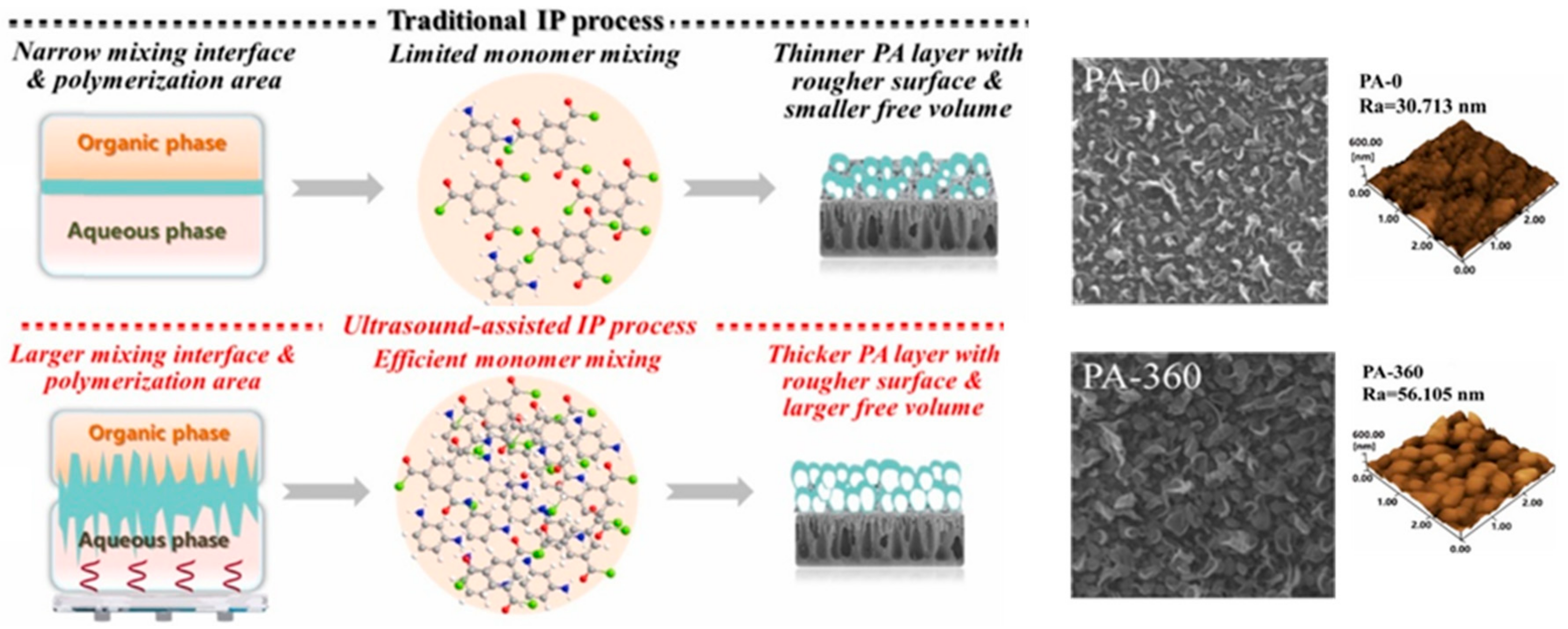
3.4. Ultrasound-Based IP Technique
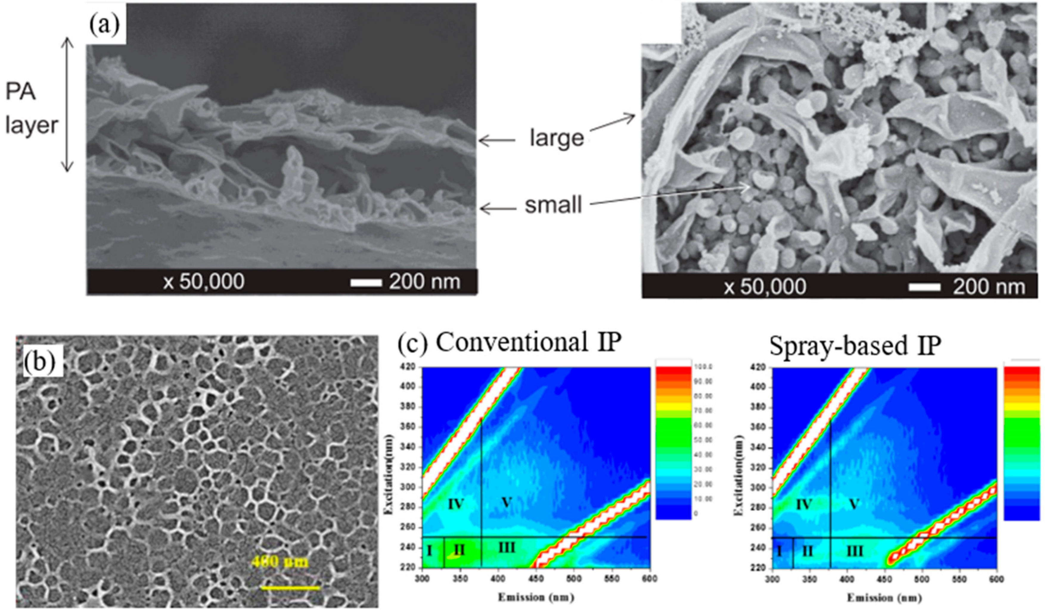
3.5. Spray-Based IP Technique
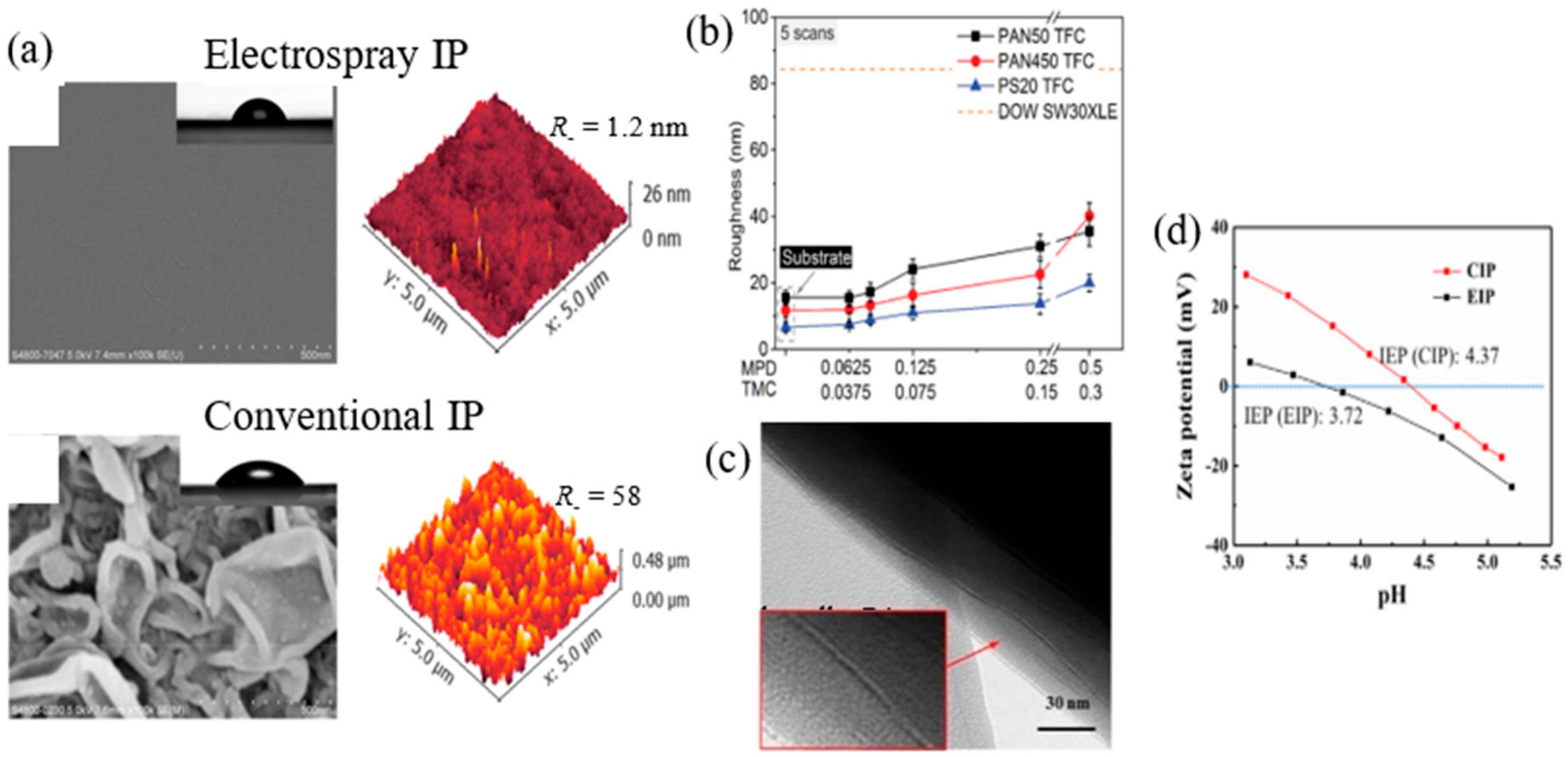
3.6. Electrospray-Based IP Technique
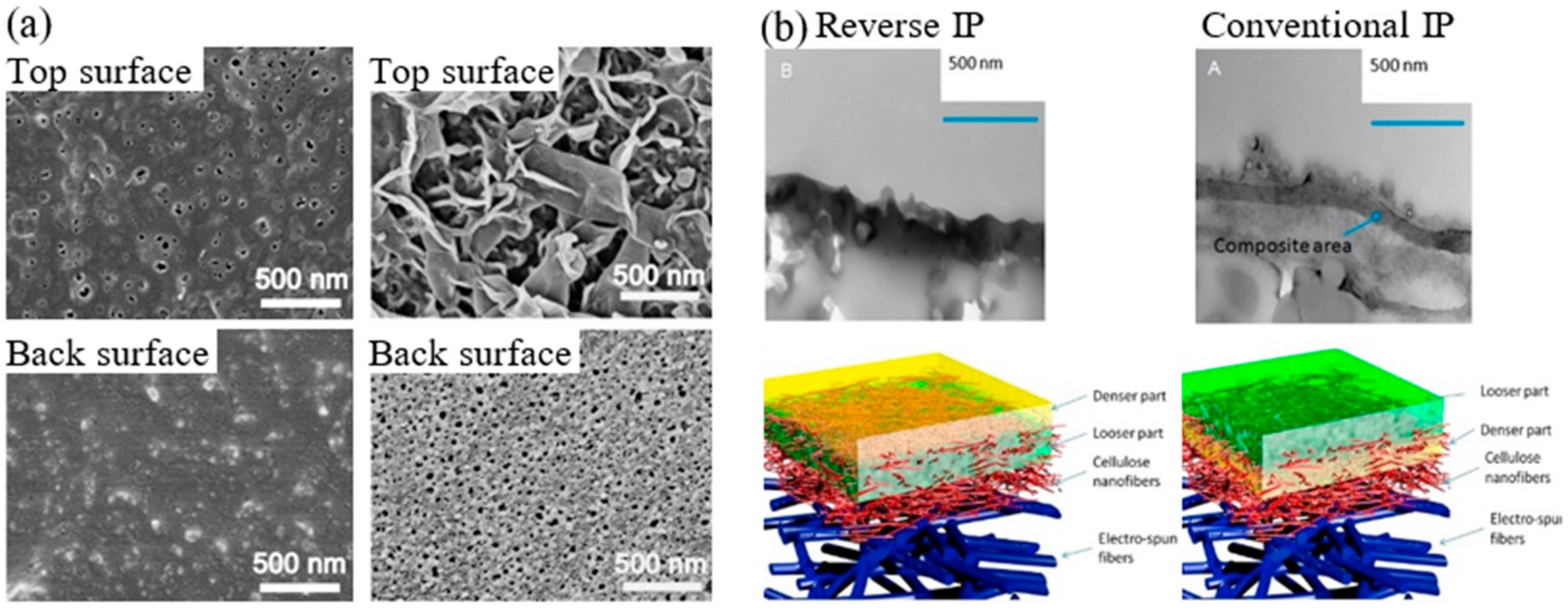
3.7. Reverse IP Technique
3.8. Summary of New or Modified IP Techniques
4. Technical Challenges of New or Modified IP Techniques
5. Conclusions and Future Outlook
Author Contributions
Funding
Acknowledgments
Conflicts of Interest
References
- Bassyouni:, M.; Abdel-Aziz, M.H.; Zoromba, M.S.; Abdel-Hamid, S.M.S.; Drioli, E. A review of polymeric nanocomposite membranes for water purification. J. Ind. Eng. Chem. 2019, 73, 19–46. [Google Scholar] [CrossRef]
- Mulyanti, R.; Susanto, H. Wastewater treatment by nanofiltration membranes. IOP Conf. Ser. Earth Environ. Sci. 2018, 142. [Google Scholar] [CrossRef]
- Peñate, B.; García-Rodríguez, L. Current trends and future prospects in the design of seawater reverse osmosis desalination technology. Desalination 2012, 284, 1–8. [Google Scholar] [CrossRef]
- Choudhary, A.; Chaudhary, A.; Onkar, S. Nanofiltration Membrane Market by Type and Application: Global Opportunity Analysis and Industry Forecast, 2018–2025; Allied Market Reaserch: Pune, India, 2019. [Google Scholar]
- Sumesh, K.; Roshan, D. Reverse Osmosis Membrane Market by Material Type, Filter Module, and Application: Global Opportunity Analysis and Industry Forecast, 2018–2025; Allied Market Research: Pune, India, 2019. [Google Scholar]
- Loeb, S.; Sourirajan, S. Sea Water Demineralization by Means of an Osmotic Membrane. Adv. Chem. ACS 1963, 38, 117–132. [Google Scholar] [CrossRef]
- Shafiq, M.; Sabir, A.; Islam, A.; Khan, S.M.; Gull, N.; Hussain, S.N.; Butt, M.T.Z. Cellulose acetate based thin film nanocomposite reverse osmosis membrane incorporated with TiO2 nanoparticles for improved performance. Carbohydr. Polym. 2018, 186, 367–376. [Google Scholar] [CrossRef] [PubMed]
- Cadotte, J.E.; Petersen, R.J.; Larson, R.E.; Erickson, E.E. A new thin-film composite seawater reverse osmosis membrane. Desalination 1980, 32, 25–31. [Google Scholar] [CrossRef]
- Xie, Q.; Shao, W.; Zhang, S.; Hong, Z.; Wang, Q.; Zeng, B. Enhancing the performance of thin-film nanocomposite nanofiltration membranes using MAH-modified GO nanosheets. RSC Adv. 2017, 7, 54898–54910. [Google Scholar] [CrossRef] [Green Version]
- Jamil, T.S.; Mansor, E.S.; Abdallah, H.; Shaban, A.M. Innovative high flux/low pressure blend thin film composite membranes for water softening. React. Funct. Polym. 2018, 131, 384–399. [Google Scholar] [CrossRef]
- Zarei, F.; Moattari, R.M.; Rajabzadeh, S.; Bagheri, M.; Taghizadeh, A.; Mohammadi, T.; Matsuyama, H. Preparation of thin film composite nano-filtration membranes for brackish water softening based on the reaction between functionalized UF membranes and polyethyleneimine. J. Membr. Sci. 2019, 588. [Google Scholar] [CrossRef]
- Li, Y.; Su, Y.; Li, J.; Zhao, X.; Zhang, R.; Fan, X.; Zhu, J.; Ma, Y.; Liu, Y.; Jiang, Z. Preparation of thin film composite nanofiltration membrane with improved structural stability through the mediation of polydopamine. J. Membr. Sci. 2015, 476, 10–19. [Google Scholar] [CrossRef]
- Ang, M.B.M.Y.; Trilles, C.A.; De Guzman, M.R.; Pereira, J.M.; Aquino, R.R.; Huang, S.H.; Hu, C.C.; Lee, K.R.; Lai, J.Y. Improved performance of thin-film nanocomposite nanofiltration membranes as induced by embedded polydopamine-coated silica nanoparticles. Sep. Purif. Technol. 2019, 113–120. [Google Scholar] [CrossRef]
- Gholami, S.; López, J.; Rezvani, A.; Vatanpour, V.; Cortina, J.L. Fabrication of thin-film nanocomposite nanofiltration membranes incorporated with aromatic amine-functionalized multiwalled carbon nanotubes. Rejection performance of inorganic pollutants from groundwater with improved acid and chlorine resistance. Chem. Eng. J. 2019, 123348. [Google Scholar] [CrossRef]
- Ang, M.B.M.Y.; Pereira, J.M.; Trilles, C.A.; Aquino, R.R.; Huang, S.H.; Lee, K.R.; Lai, J.Y. Performance and antifouling behavior of thin-film nanocomposite nanofiltration membranes with embedded silica spheres. Sep. Purif. Technol. 2019, 210, 521–529. [Google Scholar] [CrossRef]
- Jeong, B.H.; Hoek, E.M.V.; Yan, Y.; Subramani, A.; Huang, X.; Hurwitz, G.; Ghosh, A.K.; Jawor, A. Interfacial polymerization of thin film nanocomposites: A new concept for reverse osmosis membranes. J. Membr. Sci. 2007, 294, 1–7. [Google Scholar] [CrossRef]
- Lau, W.J.; Gray, S.; Matsuura, T.; Emadzadeh, D.; Chen, J.P.; Ismail, A.F. A review on polyamide thin film nanocomposite (TFN) membranes: History, applications, challenges and approaches. Water Res. 2015, 80, 306–324. [Google Scholar] [CrossRef]
- Esfahani, M.R.; Aktij, S.A.; Dabaghian, Z.; Firouzjaei, M.D.; Rahimpour, A.; Eke, J.; Escobar, I.C.; Abolhassani, M.; Greenlee, L.F.; Esfahani, A.R.; et al. Nanocomposite membranes for water separation and purification: Fabrication, modification, and applications. Sep. Purif. Technol. 2019, 213, 465–499. [Google Scholar] [CrossRef]
- Yang, Z.; Ma, X.H.; Tang, C.Y. Recent development of novel membranes for desalination. Desalination 2018, 434, 37–59. [Google Scholar] [CrossRef]
- Saleem, H.; Zaidi, S.J. Nanoparticles in reverse osmosis membranes for desalination: A state of the art review. Desalination 2020, 475, 114171. [Google Scholar] [CrossRef]
- Ng, Z.C.; Lau, W.J.; Matsuura, T.; Ismail, A.F. Thin film nanocomposite RO membranes: Review on fabrication techniques and impacts of nanofiller characteristics on membrane properties. Chem. Eng. Res. Des. 2021, 165, 81–105. [Google Scholar] [CrossRef]
- Yin, J.; Kim, E.S.; Yang, J.; Deng, B. Fabrication of a novel thin-film nanocomposite (TFN) membrane containing MCM-41 silica nanoparticles (NPs) for water purification. J. Membr. Sci. 2012, 423–424, 238–246. [Google Scholar] [CrossRef]
- Huang, H.; Qu, X.; Dong, H.; Zhang, L.; Chen, H. Role of NaA zeolites in the interfacial polymerization process towards a polyamide nanocomposite reverse osmosis membrane. RSC Adv. 2013, 3, 8203–8207. [Google Scholar] [CrossRef]
- Wang, J.; Wang, Y.; Zhang, Y.; Uliana, A.; Zhu, J.; Liu, J.; Van der Bruggen, B. Zeolitic Imidazolate Framework/Graphene Oxide Hybrid Nanosheets Functionalized Thin Film Nanocomposite Membrane for Enhanced Antimicrobial Performance. ACS Appl. Mater. Interfaces 2016, 8, 25508–25519. [Google Scholar] [CrossRef]
- Mahmoudi, E.; Ng, L.Y.; Ang, W.L.; Chung, Y.T.; Rohani, R.; Mohammad, A.W. Enhancing Morphology and Separation Performance of Polyamide 6,6 Membranes By Minimal Incorporation of Silver Decorated Graphene Oxide Nanoparticles. Sci. Rep. 2019, 9. [Google Scholar] [CrossRef] [PubMed] [Green Version]
- Fu, Q.; Wong, E.H.H.; Kim, J.; Scofield, J.M.P.; Gurr, P.A.; Kentish, S.E.; Qiao, G.G. The effect of soft nanoparticles morphologies on thin film composite membrane performance. J. Mater. Chem. A 2014, 2, 17751–17756. [Google Scholar] [CrossRef]
- Ji, Y.; Chen, G.; Liu, G.; Zhao, J.; Liu, G.; Gu, X.; Jin, W. Ultrathin Membranes with a Polymer/Nanofiber Interpenetrated Structure for High-Efficiency Liquid Separations. ACS Appl. Mater. Interfaces 2019, 11, 36717–36726. [Google Scholar] [CrossRef] [PubMed]
- Lai, G.S.; Lau, W.J.; Goh, P.S.; Ismail, A.F.; Tan, Y.H.; Chong, C.Y.; Krause-rehberg, R.; Awad, S. Tailor-made thin film nanocomposite membrane incorporated with graphene oxide using novel interfacial polymerization technique for enhanced water separation. Chem. Eng. J. 2018, 344, 524–534. [Google Scholar] [CrossRef]
- Al Aani, S.; Haroutounian, A.; Wright, C.J.; Hilal, N. Thin Film Nanocomposite (TFN) membranes modified with polydopamine coated metals/carbon-nanostructures for desalination applications. Desalination 2018, 427, 60–74. [Google Scholar] [CrossRef] [Green Version]
- Kang, X.; Liu, X.; Liu, J.; Wen, Y.; Qi, J.; Li, X. Spin-assisted interfacial polymerization strategy for graphene oxide-polyamide composite nanofiltration membrane with high performance. Appl. Surf. Sci. 2020, 508. [Google Scholar] [CrossRef]
- Chowdhury, M.R.; Steffes, J.; Huey, B.D.; Mccutcheon, J.R. 3D printed polyamide membranes for desalination. Science 2018, 686, 682–686. [Google Scholar] [CrossRef] [Green Version]
- Karan, S.; Jiang, Z.; Livingston, A. Sub-10 nm polyamide nanofilms with ultrafast solvent transport for molecular separation. Science 2015, 348, 1347–1351. [Google Scholar] [CrossRef]
- Shan, L.; Gu, J.; Fan, H.; Ji, S.; Zhang, G. Microphase Diffusion-Controlled Interfacial Polymerization for an Ultrahigh Permeability Nanofiltration Membrane. ACS Appl. Mater. Interfaces 2017, 9, 44820–44827. [Google Scholar] [CrossRef]
- Park, S.J.; Ahn, W.G.; Choi, W.; Park, S.H.; Lee, J.S.; Jung, H.W.; Lee, J.H. A facile and scalable fabrication method for thin film composite reverse osmosis membranes: Dual-layer slot coating. J. Mater. Chem. A 2017, 5, 6648–6655. [Google Scholar] [CrossRef]
- Tajuddin, M.H.; Yusof, N.; Abdullah, N.; Abidin, M.N.Z.; Salleh, W.N.W.; Ismail, A.F.; Matsuura, T.; Hairom, N.H.H.; Misdan, N. Incorporation of layered double hydroxide nanofillers in polyamide nanofiltration membrane for high performance of salts rejections. J. Taiwan Inst. Chem. Eng. 2019, 97, 1–11. [Google Scholar] [CrossRef]
- Wu, M.; Yuan, J.; Wu, H.; Su, Y.; Yang, H.; You, X.; Zhang, R.; He, X.; Khan, N.A.; Kasher, R.; et al. Ultrathin nanofiltration membrane with polydopamine-covalent organic framework interlayer for enhanced permeability and structural stability. J. Membr. Sci. 2019, 576, 131–141. [Google Scholar] [CrossRef]
- Zhang, Z.; Kang, G.; Yu, H.; Jin, Y.; Cao, Y. Fabrication of a highly permeable composite nanofiltration membrane via interfacial polymerization by adding a novel acyl chloride monomer with an anhydride group. J. Membr. Sci. 2019, 570–571, 403–409. [Google Scholar] [CrossRef]
- Lee, T.H.; Oh, J.Y.; Hong, S.P.; Lee, J.M.; Roh, S.M.; Kim, S.H.; Park, H.B. ZIF-8 particle size effects on reverse osmosis performance of polyamide thin-film nanocomposite membranes: Importance of particle deposition. J. Membr. Sci. 2019, 570–571, 23–33. [Google Scholar] [CrossRef]
- Yan, W.; Shi, M.; Wang, Z.; Zhou, Y.; Liu, L.; Zhao, S.; Ji, Y.; Wang, J.; Gao, C. Amino-modified hollow mesoporous silica nanospheres-incorporated reverse osmosis membrane with high performance. J. Membr. Sci. 2019, 581, 168–177. [Google Scholar] [CrossRef]
- Lai, G.S.; Lau, W.J.; Goh, P.S.; Ismail, A.F.; Yusof, N.; Tan, Y.H. Graphene oxide incorporated thin film nanocomposite nanofiltration membrane for enhanced salt removal performance. Desalination 2016, 387, 14–24. [Google Scholar] [CrossRef]
- Zhang, Z.; Qin, Y.; Kang, G.; Yu, H.; Jin, Y.; Cao, Y. Tailoring the internal void structure of polyamide films to achieve highly permeable reverse osmosis membranes for water desalination. J. Membr. Sci. 2020, 595, 117518. [Google Scholar] [CrossRef]
- Chong, C.Y.; Lau, W.J.; Yusof, N.; Lai, G.S.; Othman, N.H.; Matsuura, T.; Ismail, A.F. Studies on the properties of RO membranes for salt and boron removal: Influence of thermal treatment methods and rinsing treatments. Desalination 2018, 428, 218–226. [Google Scholar] [CrossRef]
- Saeedi-Jurkuyeh, A.; Jafari, A.J.; Kalantary, R.R.; Esrafili, A. A novel synthetic thin-film nanocomposite forward osmosis membrane modified by graphene oxide and polyethylene glycol for heavy metals removal from aqueous solutions. React. Funct. Polym. 2020, 146. [Google Scholar] [CrossRef]
- Zhang, Y.; Ruan, H.; Guo, C.; Liao, J.; Shen, J.; Gao, C. Thin-film nanocomposite reverse osmosis membranes with enhanced antibacterial resistance by incorporating p-aminophenol-modified graphene oxide. Sep. Purif. Technol. 2020, 234, 116017. [Google Scholar] [CrossRef]
- Seyyed Shahabi, S.; Azizi, N.; Vatanpour, V. Synthesis and characterization of novel g-C3N4 modified thin film nanocomposite reverse osmosis membranes to enhance desalination performance and fouling resistance. Sep. Purif. Technol. 2019, 215, 430–440. [Google Scholar] [CrossRef]
- Ng, Z.C.; Chong, C.Y.; Lau, W.J.; Karaman, M.; Ismail, A.F. Boron removal and antifouling properties of thin-film nanocomposite membrane incorporating PECVD-modified titanate nanotubes. J. Chem. Technol. Biotechnol. 2019, 94, 2772–2782. [Google Scholar] [CrossRef]
- Wang, F.; Zheng, T.; Xiong, R.; Wang, P.; Ma, J. Strong improvement of reverse osmosis polyamide membrane performance by addition of ZIF-8 nanoparticles: Effect of particle size and dispersion in selective layer. Chemosphere 2019, 233, 524–531. [Google Scholar] [CrossRef]
- Shao, W.; Liu, C.; Ma, H.; Hong, Z.; Xie, Q.; Lu, Y. Fabrication of pH-sensitive thin-film nanocomposite nanofiltration membranes with enhanced performance by incorporating amine-functionalized graphene oxide. Appl. Surf. Sci. 2019, 487, 1209–1221. [Google Scholar] [CrossRef]
- Kang, Y.; Obaid, M.; Jang, J.; Kim, I.S. Sulfonated graphene oxide incorporated thin film nanocomposite nanofiltration membrane to enhance permeation and antifouling properties. Desalination 2019, 470, 114125. [Google Scholar] [CrossRef]
- Xie, Q.; Zhang, S.; Ma, H.; Shao, W.; Gong, X.; Hong, Z. A novel thin-film nanocomposite nanofiltration membrane by incorporating 3D hyperbranched polymer functionalized 2D graphene oxide. Polymers 2018, 10. [Google Scholar] [CrossRef] [Green Version]
- Lai, G.S.; Lau, W.J.; Goh, P.S.; Karaman, M.; Gürsoy, M.; Ismail, A.F. Development of thin film nanocomposite membrane incorporated with plasma enhanced chemical vapor deposition-modified hydrous manganese oxide for nanofiltration process. Compos. Part B Eng. 2019, 176, 107328. [Google Scholar] [CrossRef]
- Abdikheibari, S.; Lei, W.; Dumee, L.F.; Milne, N.; Baskaran, K. Thin film Nanocomposite nanofiltration membranes from amine functionalized-boron nitride/polypiperazine amide with enhanced flux and fouling resistance. J. Mater. Chem. A 2018, 6, 12066–12081. [Google Scholar] [CrossRef]
- Wong, K.C.; Goh, P.S.; Ismail, A.F. Thin Film Nanocomposite: The Next Generation Selective Membrane for CO2 Removal. J. Mater. Chem. A 2016, 4, 15726–15748. [Google Scholar] [CrossRef]
- Zhao, W.; Liu, H.; Meng, N.; Jian, M.; Wang, H.; Zhang, X. Graphene oxide incorporated thin film nanocomposite membrane at low concentration monomers. J. Memb. Sci. 2018, 565, 380–389. [Google Scholar] [CrossRef]
- Khorshidi, B.; Bhinder, A.; Thundat, T.; Pernitsky, D.; Sadrzadeh, M. Developing high throughput thin film composite polyamide membranes for forward osmosis treatment of SAGD produced water. J. Membr. Sci. 2016, 511, 29–39. [Google Scholar] [CrossRef]
- Esmaeili, M.; Mansoorian, S.H.; Gheshlaghi, A.; Rekabdar, F. Performance and Morphology Evaluation of Thin Film Composite Polyacrylonitrile/Polyamide Nanofiltration Membranes Considering the Reaction Time. J. Water Chem. Technol. 2018, 40, 219–227. [Google Scholar] [CrossRef]
- Lv, Z.; Hu, J.; Zhang, X.; Wang, L. Enhanced surface hydrophilicity of thin-film composite membranes for nanofiltration: An experimental and DFT study. Phys. Chem. Chem. Phys. 2015, 17, 24201–24209. [Google Scholar] [CrossRef]
- Lai, G.S.; Lau, W.J.; Gray, S.R.; Matsuura, T.; Jamshidi Gohari, R.; Subramanian, M.N.; Lai, S.O.; Ong, C.S.; Ismail, A.F.; Emazadah, D.; et al. A practical approach to synthesize polyamide thin film nanocomposite (TFN) membranes with improved separation properties for water/wastewater treatment. J. Mater. Chem. A 2016, 4, 4134–4144. [Google Scholar] [CrossRef]
- Lin, S.W.; Martínez-Ayala, A.V.; Pérez-Sicairos, S.; Félix-Navarro, R.M. Preparation and characterization of low-pressure and high MgSO4 rejection thin-film composite NF membranes via interfacial polymerization process. Polym. Bull. 2019, 76, 5619–5632. [Google Scholar] [CrossRef]
- Ali, F.A.A.; Alam, J.; Shukla, A.K.; Alhoshan, M.; Abdo, B.M.A.; Al-Masry, W.A. A novel approach to optimize the fabrication conditions of thin film composite ro membranes using multi-objective genetic algorithm II. Polymers 2020, 12. [Google Scholar] [CrossRef] [Green Version]
- Khorshidi, B.; Thundat, T.; Fleck, B.A.; Sadrzadeh, M. A novel approach toward fabrication of high performance thin film composite polyamide membranes. Sci. Rep. 2016, 6. [Google Scholar] [CrossRef] [Green Version]
- Sani, N.A.A.; Lau, W.J.; Nordin, N.A.H.M.; Ismail, A.F. Influence of organic solvents and operating conditions on the performance of polyphenylsulfone (PPSU)/copper-1,3,5-benzenetricarboxylate (Cu-BTC) solvent resistant nanofiltration (SRNF) membranes. Chem. Eng. Res. Des. 2016, 115, 66–76. [Google Scholar] [CrossRef]
- Jiang, C.; Zhang, L.; Li, P.; Sun, H.; Hou, Y.; Niu, Q.J. Ultrathin-film composite membranes fabricated by novel in-situ free interfacial polymerization for desalination. ACS Appl. Mater. Interfaces 2020. [Google Scholar] [CrossRef] [PubMed]
- Misdan, N.; Ramlee, N.; Hairom, N.H.H.; Ikhsan, S.N.W.; Yusof, N.; Lau, W.J.; Ismail, A.F.; Nordin, N.A.H.M. CuBTC metal organic framework incorporation for enhancing separation and antifouling properties of nanofiltration membrane. Chem. Eng. Res. Des. 2019, 148, 227–239. [Google Scholar] [CrossRef]
- Misdan, N.; Lau, W.J.; Ismail, A.F.; Matsuura, T. Formation of thin film composite nanofiltration membrane: Effect of polysulfone substrate characteristics. Desalination 2013, 329, 9–18. [Google Scholar] [CrossRef] [Green Version]
- Misdan, N.; Lau, W.J.; Ismail, A.F.; Matsuura, T.; Rana, D. Study on the thin film composite poly(piperazine-amide) nanofiltration membrane: Impacts of physicochemical properties of substrate on interfacial polymerization formation. Desalination 2014, 344, 198–205. [Google Scholar] [CrossRef] [Green Version]
- Li, J.; Wei, M.; Wang, Y. Substrate matters: The influences of substrate layers on the performances of thin-film composite reverse osmosis membranes. Chin. J. Chem. Eng. 2017, 25, 1676–1684. [Google Scholar] [CrossRef]
- Lau, W.J.; Lai, G.S.; Li, J.; Gray, S.; Hu, Y.; Misdan, N.; Goh, P.S.; Matsuura, T.; Azelee, I.W.; Ismail, A.F. Development of microporous substrates of polyamide thin film composite membranes for pressure-driven and osmotically-driven membrane processes: A review. J. Ind. Eng. Chem. 2019, 77, 25–59. [Google Scholar] [CrossRef]
- Zhu, J.; Yuan, S.; Uliana, A.; Hou, J.; Li, J.; Li, X.; Tian, M.; Chen, Y.; Volodin, A.; Bruggen, B.V.D. High-flux thin film composite membranes for nanofiltration mediated by a rapid co-deposition of polydopamine/piperazine. J. Membr. Sci. 2018, 554, 97–108. [Google Scholar] [CrossRef]
- Pan, Y.; Xu, R.; Lü, Z.; Yu, S.; Liu, M.; Gao, C. Enhanced both perm-selectivity and fouling resistance of poly(piperazineamide) nanofiltration membrane by incorporating sericin as a co-reactant of aqueous phase. J. Membr. Sci. 2017, 523, 282–290. [Google Scholar] [CrossRef]
- Yin, J.; Zhu, G.; Deng, B. Graphene oxide (GO) enhanced polyamide (PA) thin-film nanocomposite (TFN) membrane for water purification. Desalination 2016, 379, 93–101. [Google Scholar] [CrossRef]
- Wu, H.; Tang, B.; Wu, P. MWNTs/polyester thin film nanocomposite membrane: An approach to overcome the trade-off effect between permeability and selectivity. J. Phys. Chem. C 2010, 114, 16395–16400. [Google Scholar] [CrossRef]
- Yanar, N.; Son, M.; Park, H.; Choi, H. Toward greener membranes with 3D printing technology. Environ. Eng. Res. 2020, 26, 200027. [Google Scholar] [CrossRef] [Green Version]
- Trivedi, J.S.; Bhalani, D.V.; Bhadu, G.R.; Jewrajka, S.K. Multifunctional amines enable the formation of polyamide nanofilm composite ultrafiltration and nanofiltration membranes with modulated charge and performance. J. Mater. Chem. A 2018, 6, 20242–20253. [Google Scholar] [CrossRef]
- Park, S.J.; Choi, W.; Nam, S.E.; Hong, S.; Lee, J.S.; Lee, J.H. Fabrication of polyamide thin film composite reverse osmosis membranes via support-free interfacial polymerization. J. Membr. Sci. 2017, 526, 52–59. [Google Scholar] [CrossRef]
- Cui, Y.; Liu, X.Y.; Chung, T.S. Ultrathin Polyamide Membranes Fabricated from Free-Standing Interfacial Polymerization: Synthesis, Modifications, and Post-treatment. Ind. Eng. Chem. Res. 2017, 56, 513–523. [Google Scholar] [CrossRef]
- Zhu, J.; Hou, J.; Zhang, R.; Yuan, S.; Li, J.; Tian, M.; Wang, P.; Zhang, Y.; Alexander, V.; Van der Bruggen, B. Rapid water transport through controllable, ultrathin polyamide nanofilms for high-performance nanofiltration. J. Mater. Chem. A 2018, 13828–13841. [Google Scholar] [CrossRef]
- Lin, J.; Tang, C.Y.; Huang, C.; Tang, Y.P.; Ye, W.; Li, J.; Shen, J.; Van den Broeck, R.; Van Impe, J.; Volodin, A.; et al. A comprehensive physico-chemical characterization of superhydrophilic loose nanofiltration membranes. J. Membr. Sci. 2016, 501, 1–14. [Google Scholar] [CrossRef]
- Jiang, Z.; Karan, S.; Livingston, A.G. Water Transport through Ultrathin Polyamide Nanofilms Used for Reverse Osmosis. Adv. Mater. 2018, 30, 1–7. [Google Scholar] [CrossRef]
- Song, X.; Gan, B.; Yang, Z.; Tang, C.Y.; Gao, C. Confined nanobubbles shape the surface roughness structures of thin film composite polyamide desalination membranes. J. Memb. Sci. 2019, 582, 342–349. [Google Scholar] [CrossRef]
- Zhang, R.; Yu, S.; Shi, W.; Zhu, J.; Van der Bruggen, B. Support membrane pore blockage (SMPB): An important phenomenon during the fabrication of thin film composite membrane via interfacial polymerization. Sep. Purif. Technol. 2019, 215, 670–680. [Google Scholar] [CrossRef]
- Park, S.; Lee, J. Fabrication of high-performance reverse osmosis membranes via dual-layer slot coating with tailoring interfacial adhesion. J. Membr. Sci. 2020, 118449. [Google Scholar] [CrossRef]
- Ma, Z.-Y.; Zhang, X.; Liu, C.; Dong, S.-N.; Yang, J.; Wu, G.-P.; Xu, Z.-K. Polyamide nanofilms synthesized via controlled interfacial polymerization on a “jelly” surface. Chem. Commun. 2020. [Google Scholar] [CrossRef] [PubMed]
- Jiang, C.; Tian, L.; Zhai, Z.; Shen, Y.; Dong, W.; He, M.; Hou, Y.; Niu, Q.J. Thin-film composite membranes with aqueous template-induced surface nanostructures for enhanced nanofiltration. J. Membr. Sci. 2019, 589, 117244. [Google Scholar] [CrossRef]
- Wang, Z.; Wang, Z.; Lin, S.; Jin, H.; Gao, S.; Zhu, Y.; Jin, J. Nanoparticle-templated nanofiltration membranes for ultrahigh performance desalination. Nat. Commun. 2018, 9. [Google Scholar] [CrossRef] [PubMed]
- Wu, M.; Lv, Y.; Yang, H.; Liu, L.; Zhang, X.; Xu, Z. Thin film composite membranes combining carbon nanotube intermediate layer and microfiltration support for high nanofiltration performances. J. Membr. Sci. 2016, 515, 238–244. [Google Scholar] [CrossRef]
- Lai, G.S.; Lau, W.J.; Goh, P.S.; Tan, Y.H.; Ng, B.C.; Ismail, A.F. A novel interfacial polymerization approach towards synthesis of graphene oxide-incorporated thin film nanocomposite membrane with improved surface properties. Arab. J. Chem. 2019, 12, 75–87. [Google Scholar] [CrossRef]
- Zhu, J.; Hou, J.; Yuan, S.; Zhao, Y.; Li, Y.; Zhang, R.; Tian, M.; Li, J.; Wang, J.; Van Der Bruggen, B. MOF-positioned polyamide membranes with a fishnet-like structure for elevated nanofiltration performance. J. Mater. Chem. A 2019, 7, 16313–16322. [Google Scholar] [CrossRef]
- Ren, Y.; Zhu, J.; Cong, S.; Wang, J.; Van der Bruggen, B.; Liu, J.; Zhang, Y. High flux thin film nanocomposite membranes based on porous organic polymers for nanofiltration. J. Membr. Sci. 2019, 585, 19–28. [Google Scholar] [CrossRef]
- Wu, M.; Ma, T.; Su, Y.; Wu, H.; You, X.; Jiang, Z.; Kasher, R. Fabrication of composite nanofiltration membrane by incorporating attapulgite nanorods during interfacial polymerization for high water flux and antifouling property. J. Membr. Sci. 2017, 544, 79–87. [Google Scholar] [CrossRef]
- Zheng, Q.; Wang, C.; Ma, G.; Jin, M.; Cheng, S.; Lai, Y.; Yu, J. Annealing temperature impact on Sb2S3 solar cells prepared by spin-coating method. Mater. Lett. 2019, 243, 104–107. [Google Scholar] [CrossRef]
- Cao, L.; Yang, N.; Li, S.; Ye, X.; Yuan, X.; Li, H.; Tong, H. Alumina film deposited by spin-coating method for silicon wafer surface passivation. J. Mater. Sci. Mater. Electron. 2020, 31, 2686–2690. [Google Scholar] [CrossRef]
- Huang, Y.; Dan, N.; Dan, W.; Zhao, W.; Bai, Z.; Chen, Y.; Yang, C. Facile fabrication of gelatin and polycaprolactone based bilayered membranes via spin coating method with antibacterial and cyto-compatible properties. Int. J. Biol. Macromol. 2019, 124, 699–707. [Google Scholar] [CrossRef] [PubMed]
- Wang, Z.; Ma, J.; Wang, P. Optimization of membrane structure using the Spin-coating method. Desalin. Water Treat. 2011, 34, 197–203. [Google Scholar] [CrossRef]
- An, Q.F.; Hung, W.S.; Lo, S.C.; Li, Y.H.; De Guzman, M.; Hu, C.C.; Lee, K.R.; Jean, Y.C.; Lai, J.Y. Comparison between free volume characteristics of composite membranes fabricated through static and dynamic interfacial polymerization processes. Macromolecules 2012, 45, 3428–3435. [Google Scholar] [CrossRef]
- Jimenez-Solomon, M.F.; Song, Q.; Jelfs, K.E.; Munoz-Ibanez, M.; Livingston, A.G. Polymer nanofilms with enhanced microporosity by interfacial polymerization. Nat. Mater. 2016, 15, 760–767. [Google Scholar] [CrossRef] [PubMed] [Green Version]
- Yuan, T.; Hu, Y.; He, M.; Zhao, S.; Lan, H.; Li, P.; Jason Niu, Q. Spinning-assist layer-by-layer assembled polysulfonamide membrane for reverse osmosis from naphthalene-1,3,6-trisulfonylchloride and piperazine. J. Appl. Polym. Sci. 2018, 136, 1–9. [Google Scholar] [CrossRef]
- He, M.; Yuan, T.; Dong, W.; Li, P.; Jason Niu, Q.; Meng, J. High-performance acid-stable polysulfonamide thin-film composite membrane prepared via spinning-assist multilayer interfacial polymerization. J. Mater. Sci. 2018, 54, 886–900. [Google Scholar] [CrossRef]
- Chan, E.P.; Lee, J.H.; Chung, J.Y.; Stafford, C.M. An automated spin-assisted approach for molecular layer-by-layer assembly of crosslinked polymer thin films. Rev. Sci. Instrum. 2012, 83. [Google Scholar] [CrossRef]
- Chan, E.P.; Young, A.P.; Lee, J.H.; Stafford, C.M. Swelling of ultrathin molecular layer-by-layer polyamide water desalination membranes. J. Polym. Sci. Part B Polym. Phys. 2013, 51, 1647–1655. [Google Scholar] [CrossRef]
- Shen, L.; Hung, W.S.; Zuo, J.; Zhang, X.; Lai, J.Y.; Wang, Y. High-performance thin-film composite polyamide membranes developed with green ultrasound-assisted interfacial polymerization. J. Membr. Sci. 2019, 570–571, 112–119. [Google Scholar] [CrossRef]
- Shen, L.; Hung, W.S.; Zuo, J.; Tian, L.; Yi, M.; Ding, C.; Wang, Y. Effect of ultrasonication parameters on forward osmosis performance of thin film composite polyamide membranes prepared with ultrasound-assisted interfacial polymerization. J. Membr. Sci. 2020, 599, 117834. [Google Scholar] [CrossRef]
- Mason, T.J.; Riera, E.; Vercet, A.; Lopez-buesa, P. Application of Ultrasound. In Emerging Technologies for Food Processing: An Overview; Elsevier: Amsterdam, The Netherlands, 2005; pp. 323–351. ISBN 0126767572. [Google Scholar]
- Córdova, A.; Astudillo-Castro, C.; Ruby-Figueroa, R.; Valencia, P.; Soto, C. Recent advances and perspectives of ultrasound assisted membrane food processing. Food Res. Int. 2020, 133, 109163. [Google Scholar] [CrossRef] [PubMed]
- Fischer, C.; Krix, M.; Weber, M.A.; Loizides, A.; Gruber, H.; Jung, E.M.; Klauser, A.; Radzina, M.; Dietrich, C.F. Contrast-Enhanced Ultrasound for Musculoskeletal Applications: A World Federation for Ultrasound in Medicine and Biology Position Paper. Ultrasound Med. Biol. 2020. [Google Scholar] [CrossRef] [PubMed]
- Tu, S.H.-L.; Tsai, P.-Y. A Class-E high-voltage pulse generator for ultrasound medical imaging applications. Microelectron. J. 2020, 104776. [Google Scholar] [CrossRef]
- Chen, R.; Wang, X.-L.; Xue, W.-L.; Sun, J.-W.; Dong, X.-Y.; Jiang, Z.-P.; Wu, H.; Ma, R.; Zhou, X.-L. Application value of conventional ultrasound and real-time shear wave elastography in patients with type 2 diabetic polyneuropathy. Eur. J. Radiol. 2020, 126, 108965. [Google Scholar] [CrossRef] [PubMed]
- Naji, O.; Al-juboori, R.A.; Bowtell, L.; Alpatova, A.; Ghaffour, N. Direct contact ultrasound for fouling control and flux enhancement in air-gap membrane distillation. Ultrason. Sonochem. 2020, 61, 104816. [Google Scholar] [CrossRef] [PubMed]
- Qasim, M.; Darwish, N.N.; Mhiyo, S.; Darwish, N.A.; Hilal, N. The use of ultrasound to mitigate membrane fouling in desalination and water treatment. Desalination 2018, 443, 143–164. [Google Scholar] [CrossRef] [Green Version]
- Thombre, N.V.; Gadhekar, A.P.; Patwardhan, A.V.; Gogate, P.R. Ultrasound induced cleaning of polymeric nanofiltration membranes. Ultrason. Sonochem. 2020, 62, 104891. [Google Scholar] [CrossRef] [PubMed]
- Ang, M.B.M.Y.; Deang, A.B.G.; Aquino, R.R.; Basilia, B.A.; Huang, S.H.; Lee, K.R.; Lai, J.Y. Assessing the performance of thin-film nanofiltration membranes with embedded montmorillonites. Membranes 2020, 10, 79. [Google Scholar] [CrossRef]
- Tsuru, T.; Sasaki, S.; Kamada, T.; Shintani, T.; Ohara, T.; Nagasawa, H.; Nishida, K.; Kanezashi, M.; Yoshioka, T. Multilayered polyamide membranes by spray-assisted 2-step interfacial polymerization for increased performance of trimesoyl chloride (TMC)/m-phenylenediamine (MPD)-derived polyamide membranes. J. Membr. Sci. 2013, 446, 504–512. [Google Scholar] [CrossRef]
- Morales-Cuevas, J.B.; Pérez-Sicairos, S.; Lin, S.W.; Salazar-Gastélum, M.I. Evaluation of a modified spray-applied interfacial polymerization method for preparation of nanofiltration membranes. J. Appl. Polym. Sci. 2019, 136, 1–10. [Google Scholar] [CrossRef]
- Tang, J.; Wang, H.; Gomez, A. Controlled nanoparticle synthesis via opposite-polarity electrospray pyrolysis. J. Aerosol Sci. 2017, 113, 201–211. [Google Scholar] [CrossRef]
- Wang, J.; Li, C.; Chen, D.; Sun, C.; Yang, Z. Interlayered MoS2/rGO thin film for efficient lithium storage produced by electrospray deposition and far-infrared reduction. Appl. Surf. Sci. 2020, 499, 143940. [Google Scholar] [CrossRef]
- Wang, Y.; Zhang, R.; Qin, W.; Dai, J.; Zhang, Q.; Lee, K.J.; Liu, Y. Physicochemical properties of gelatin films containing tea polyphenol-loaded chitosan nanoparticles generated by electrospray. Mater. Des. 2020, 185, 108277. [Google Scholar] [CrossRef]
- Zhu, Y.; Chiarot, P.R. Directed assembly of nanomaterials using electrospray deposition and substrate-level patterning. Powder Technol. 2020, 364, 845–850. [Google Scholar] [CrossRef]
- Jaworek, A.; Sobczyk, A.T. Electrospraying route to nanotechnology: An overview. J. Electrostat. 2008, 66, 197–219. [Google Scholar] [CrossRef]
- Yanilmaz, M.; Lu, Y.; Dirican, M.; Fu, K.; Zhang, X. Nanoparticle-on-nanofiber hybrid membrane separators for lithium-ion batteries via combining electrospraying and electrospinning techniques. J. Membr. Sci. 2014, 456, 57–65. [Google Scholar] [CrossRef]
- Ao, C.; Yuan, W.; Zhao, J.; He, X.; Zhang, X.; Li, Q.; Xia, T.; Zhang, W.; Lu, C. Superhydrophilic graphene oxide@electrospun cellulose nanofiber hybrid membrane for high-efficiency oil/water separation. Carbohydr. Polym. 2017, 175, 216–222. [Google Scholar] [CrossRef]
- Ge, J.; Zhang, J.; Wang, F.; Li, Z.; Yu, J.; Ding, B. Superhydrophilic and underwater superoleophobic nanofibrous membrane with hierarchical structured skin for effective oil-in-water emulsion separation. J. Mater. Chem. A 2017, 5, 497–502. [Google Scholar] [CrossRef]
- Su, C.; Horseman, T.; Cao, H.; Christie, K.S.S.; Li, Y.; Lin, S. Robust Superhydrophobic Membrane for Membrane Distillation with Excellent Scaling Resistance. Environ. Sci. Technol. 2019. [Google Scholar] [CrossRef]
- Moon, S.J.; Kim, J.H.; Seong, J.G.; Lee, W.H.; Park, S.H.; Noh, S.H.; Kim, J.H.; Lee, Y.M. Thin film composite on fluorinated thermally rearranged polymer nanofibrous membrane achieves power density of 87 W m−2 in pressure retarded osmosis, improving economics of osmotic heat engine. J. Membr. Sci. 2020, 607, 118120. [Google Scholar] [CrossRef]
- Moon, S.J.; Lee, S.M.; Kim, J.H.; Park, S.H.; Wang, H.H.; Kim, J.H.; Lee, Y.M. A highly robust and water permeable thin film composite membranes for pressure retarded osmosis generating 26 W·m−2 at 21 bar. Desalination 2020, 483, 114409. [Google Scholar] [CrossRef]
- Satinderpal, K.; Subramanian, S.; Renuga, G.; Seeram, R. Formation and Characterization of Polyamide Composite Electrospun Nanofibrous Membranes for Salt Separation Satinderpal. J. Appl. Polym. Sci. 2012, 124, 205–215. [Google Scholar] [CrossRef]
- Ma, X.H.; Yang, Z.; Yao, Z.K.; Guo, H.; Xu, Z.L.; Tang, C.Y. Interfacial Polymerization with Electrosprayed Microdroplets: Toward Controllable and Ultrathin Polyamide Membranes. Environ. Sci. Technol. Lett. 2018, 5, 117–122. [Google Scholar] [CrossRef]
- Yang, S.; Wang, J.; Fang, L.; Lin, H.; Liu, F.; Tang, C.Y. Electrosprayed polyamide nanofiltration membrane with intercalated structure for controllable structure manipulation and enhanced separation performance. J. Membr. Sci. 2020, 602, 117971. [Google Scholar] [CrossRef]
- Chen, J.; Zhang, J.; Wu, X.; Cui, X.; Li, W.; Zhang, H.; Wang, J.; Cao, X.Z.; Zhang, P. Accurately controlling the hierarchical nanostructure of polyamide membranes: Via electrostatic atomization-assisted interfacial polymerization. J. Mater. Chem. A 2020, 8, 9160–9167. [Google Scholar] [CrossRef]
- Mahdavi, H.; Moslehi, M. A new thin film composite nanofiltration membrane based on PET nanofiber support and polyamide top layer: Preparation and characterization. J. Polym. Res. 2016, 23, 1–9. [Google Scholar] [CrossRef]
- Qanati, O.; Ahmadi, A.; Seyed dorraji, M.S.; Rasoulifard, M.H.; Vatanpour, V. Thin-film nanofiltration membrane with monomers of 1,2,4,5-benzene tetracarbonyl chloride and ethylene diamine on electrospun support: Preparation, morphology and chlorine resistance properties. Polym. Bull. 2018, 75, 3407–3425. [Google Scholar] [CrossRef]
- Wang, X.; Yeh, T.M.; Wang, Z.; Yang, R.; Wang, R.; Ma, H.; Hsiao, B.S.; Chu, B. Nanofiltration membranes prepared by interfacial polymerization on thin-film nanofibrous composite scaffold. Polymer 2014, 55, 1358–1366. [Google Scholar] [CrossRef]
- Shen, K.; Cheng, C.; Zhang, T.; Wang, X. High performance polyamide composite nanofiltration membranes via reverse interfacial polymerization with the synergistic interaction of gelatin interlayer and trimesoyl chloride. J. Membr. Sci. 2019, 588, 117192. [Google Scholar] [CrossRef]
- Yan, H.; Miao, X.; Xu, J.; Pan, G.; Zhang, Y.; Shi, Y.; Guo, M.; Liu, Y. The porous structure of the fully-aromatic polyamide film in reverse osmosis membranes. J. Membr. Sci. 2015, 475, 504–510. [Google Scholar] [CrossRef]


| Year | Authors | Support-Free IP Conditions | Application | a Performance Comparison | Unique PA Structure | |
|---|---|---|---|---|---|---|
| Conventional IP | Support-Free IP (Optimum Membrane) | |||||
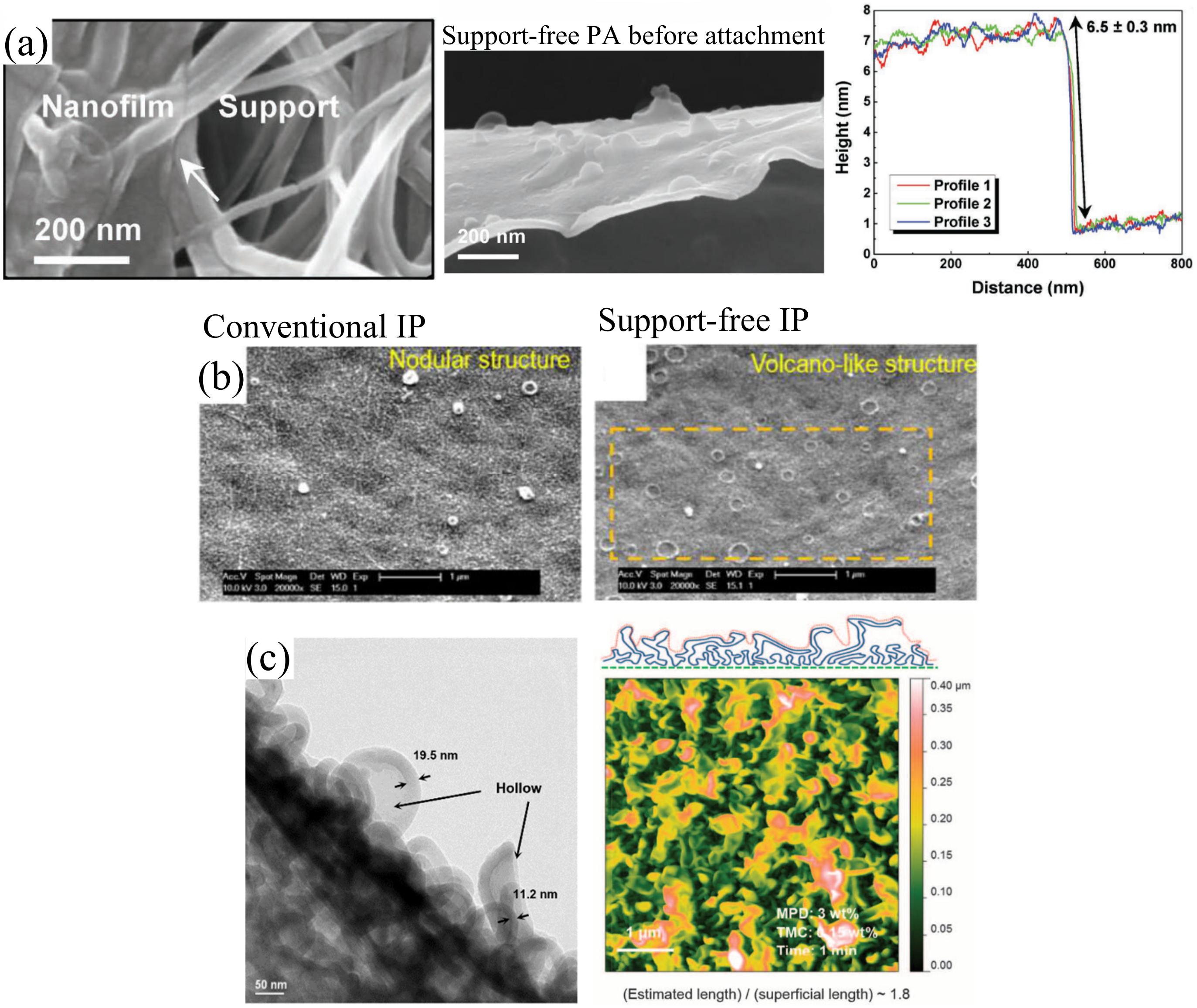
| 2016 | Karan et al. [32] | Immersion of nanostrand coated XP84 substrate into 3 wt % MPD followed by 0.15 wt % TMC. Nanostrand interlayer was removed via acid dissolution or HCl generated from IP reaction. | OSN | Commercial membrane (DuraMem DM150) Methanol permeance: ~0.48 L/m2·h·bar Acetonitrile permeance: 0.47 L/m2·h·bar | Methanol permeance: 52.2 L/m2·h·bar Acetonitrile permeance: 112 L/m2·h·bar Methyl orange rejection: 98.9% | -Crumpled/ridge-and-valley structures observed -Ultrathin PA layer (~8 nm) |
| 2017 | Park et al. [75] | Support-free PA was crosslinked between 3 wt % MPD and 0.1 wt % TMC. It was followed by drainage of excess solutions for attachment onto hydrolyzed polyacrylonitrile (PAN50) substrate. | RO | Permeability: 0.81 L/m2·h·bar (NaCl) NaCl rejection: 95.7% Zeta potential: −29.2 mV CA: 69.8° | Permeability: 0.86 L/m2·h·bar (NaCl) NaCl rejection: 99% Zeta potential: −22.3 mV CA: 67.2° | -Defect-free, thinner and smoother PA structure -Absence of typical ridge-and-valley structures (only nodules were formed) |
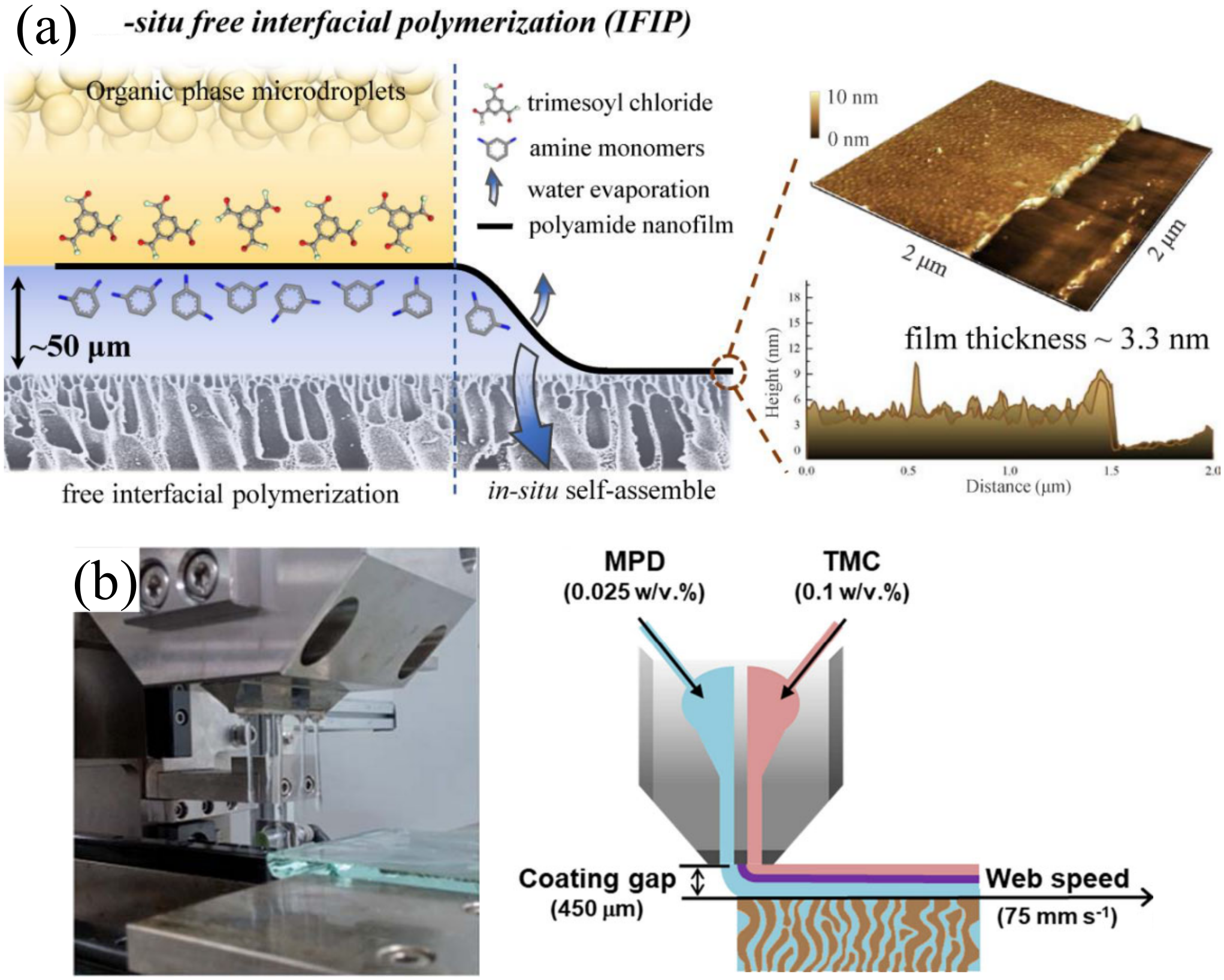
| 2017 | Park et al. [34] | Support-free PA was developed by using 0.025 wt % MPD and 0.1 wt % TMC. Both monomer solutions were spread through a slot die nozzle) followed by self-attachment onto hydrolyzed PAN50 substrate. | RO | Permeability: 1.55 L/m2·h·bar (NaCl) NaCl rejection: 68.7% Zeta potential: ~-29.5 mV CA: 71.8° | Permeability: 2.05 L/m2·h·bar (NaCl) NaCl rejection: 99.1% Zeta potential: ~-23.1 mV CA: 65.8° | -Smoother PA with ultrathin layer (~9 nm) -Absence of typical ridge-and-valley structure -Higher crosslinking degree of PA layer |
| 2017 | Cui et al. [76] | Formation of support-free PA, using 2 wt % MPD and 0.1 wt % TMC. Excess solution was drained after >5 h. The PA layer supported by track-etched membrane or non-woven fabric was then post-treated in DMF solution | FO | n/a | Jv: ~6.2 L/m2.h Js: ~0.12 g/m2.h | -Typical ridge-and-valley structure formed |
| RO | Commercial membrane (Dow SW30XLE) PWP b: 0.7 L/m2·h·bar NaCl rejection b: 99.7% | PWP: 2.31 L/m2·h·bar NaCl rejection: 96% | ||||
| 2018 | Zhu et al. [77] | Support-free PA was established with 0.025 wt % PIP and 0.05 wt % TMC followed by filtration of aqueous solution through PAN400C substrate | NF | Commercial membrane (Sepro NF 2A) [78] PWP: 10.1 L/m2·h·bar NaCl rejection: 24.8% | PWP: 25.1 L/m2·h·bar Na2SO4 rejection: 99.1% NaCl rejection: 28% | - Extremely thin PA layer (12 nm) - PA with sparse volcano-like structure was obtained |
| 2018 | Jiang et al. [79] | Formation of support-free PA (3 wt % MPD and 0.15 wt % TMC) followed by floating nanofilm on water surface and manual attachment onto PSf support membrane | RO | Commercial membrane (Dow SW30XLE) PWP b: 0.71 L/m2·h·bar NaCl rejection b: 99.7% | Permeability: 2.69 L/m2·h·bar (NaCl) NaCl rejection: 96% | -Ultrathin PA layer (~6 nm) -Formation of nodules that are similar to typical NF membranes. |
| 2018 | Trivedi et al. [74] | Formation of support-free PA (0.05 wt % PEI and 0.05 wt % TMC) followed by manual attachment onto polyethersulfone (PES) support membrane | NF | Permeability: ~20 L/m2·h·bar (Na2SO4) Na2SO4 rejection: ~85% NaCl rejection: ~27% | Permeability: ~20 L/m2·h·bar (Na2SO4) Na2SO4 rejection: ~82% NaCl rejection: ~30% | -Thin PA layer formed (~25 nm) -PA layer with similar roughness and thickness was obtained |
| 2019 | Song et al. [80] | Formation of support-free PA (2 wt % MPD and 0.1 wt % TMC) followed by filtration of aqueous solution through PSf substrate | RO | Permeability: ~1.55 L/m2·h·bar (NaCl) NaCl rejection: ~99% | Permeability: 0.94 L/m2·h·bar (NaCl) NaCl rejection: 96.4% | - PA layer with significantly smoother surface was achieved -Absence of typical ridge-and-valley structures. |
| 2019 | Zhang et al. [81] | Formation of support-free PA (0.6 wt % PIP and 0.025 wt % TMC) followed by drainage of excess solutions for attachment onto PES substrate | NF | PWP: ~16.3 L/m2·h·bar Na2SO4 rejection: ~99% MgCl2 rejection: ~94% | PWP: ~19.7 L/m2·h·bar Na2SO4 rejection: ~99% MgCl2 rejection: ~94% | -Distinct boundary between PA and support membrane -No SMPB observed |
| (After ethanol immersion) PWP: ~18.7 L/m2·h·bar Na2SO4 rejection: ~98% MgCl2 rejection: ~90% | (After ethanol immersion) PWP: ~260 L/m2·h·bar Na2SO4 rejection: <5% MgCl2 rejection: <5% | |||||
| 2020 | Park and Lee [82] | Formation of support-free PA (0.025 wt % MPD and 0.1 wt % TMC, both spread through a slot die nozzle) followed self-attachment onto modified PSf support membrane | RO | Commercial membrane (Nitto SWC4+) Permeability: 1.6 L/m2·h·bar NaCl rejection: 99.2% | Permeability: 3 L/m2·h·bar (NaCl) NaCl rejection: 99.2% | -Ultrathin PA layer (~7 nm) |
| 2020 | Jiang et al. [63] | Formation of support-free PA via microscale dispersion of 0.05 wt % TMC onto modified PSf support membrane with unremoved residual PIP (0.025 wt %) | NF | Commercial membrane (Dow NF270) PWP b: ~12.07 L/m2·h·bar MgSO4 rejection b: >97% | Permeability: ~26.6 L/m2·h·bar (Na2SO4) Na2SO4 rejection: 98.7% | -Ultrathin PA layers -Smooth PA with slight nodular structures |
| Formation of support-free PA via microscale dispersion of 0.05 wt % TMC onto modified PSf support membrane with unremoved residual MPD (0.025 wt %) | RO | Commercial membrane (Dow SW30XLE) PWP b: 0.7 L/m2·h·bar NaCl rejection b: 99.7% | Permeability: 2.9 L/m2·h·bar (NaCl) NaCl rejection: 98.3% | |||
| 2020 | Ma et al. [83] | Formation of PA on hexane–jelly interface (0.02 wt % PIP in jelly and 0.07 wt % TMC in hexane). The jelly was then dissolved and support-free PA was manually attached to the PES substrate via vacuum filtration adhesion | NF | Commercial membrane (Dow NF270) PWP b: ~12.07 L/m2·h·bar MgSO4 rejection b: >97% | Permeability: ~26 L/m2·h·bar (Na2SO4) Na2SO4 rejection: 97.7% | -PA layer with thinner and smoother structure was developed |
| Year | Authors | Filtration IP Conditions | Application | a Performance Comparison | a Unique PA Structure | |
|---|---|---|---|---|---|---|
| Conventional IP | Filtration IP (Optimum Membrane) | |||||
| 2017 | Wu et al. [90] | Filtration of 0.1 wt % PIP containing 5 mg attapulgite through PES substrate followed by contact with 1 wt % TMC | NF | Commercial NF membrane (Sepro NF 2A) [78] PWP: 10.1 L/m2·h·bar NaCl rejection: 24.8% | PWP: 23 L/m2·h·bar Na2SO4 rejection: 92% FRR: 95.7% (tested with 1 g/L humic acid for 42.5 h) | - Even nanomaterial distribution - Rough PA layer (1.37 roughness area ratio) |
| 2018 | Al Aani et al. [29] | Filtration of 2 wt % MPD through metal oxide/CNT-coated (0.0025 mg/cm2) PES substrate followed by contact with 0.1 wt % TMC | RO | Commercial RO membrane (Dow SW30XLE) PWP b: 0.7 L/m2·h·bar NaCl rejection b: 99.7% | PWP: >0.95 L/m2·h·bar NaCl rejection: >90% | - Even nanomaterial distribution - Smooth PA layer (Ra: ~10 nm) - Increased hydrophilicity |
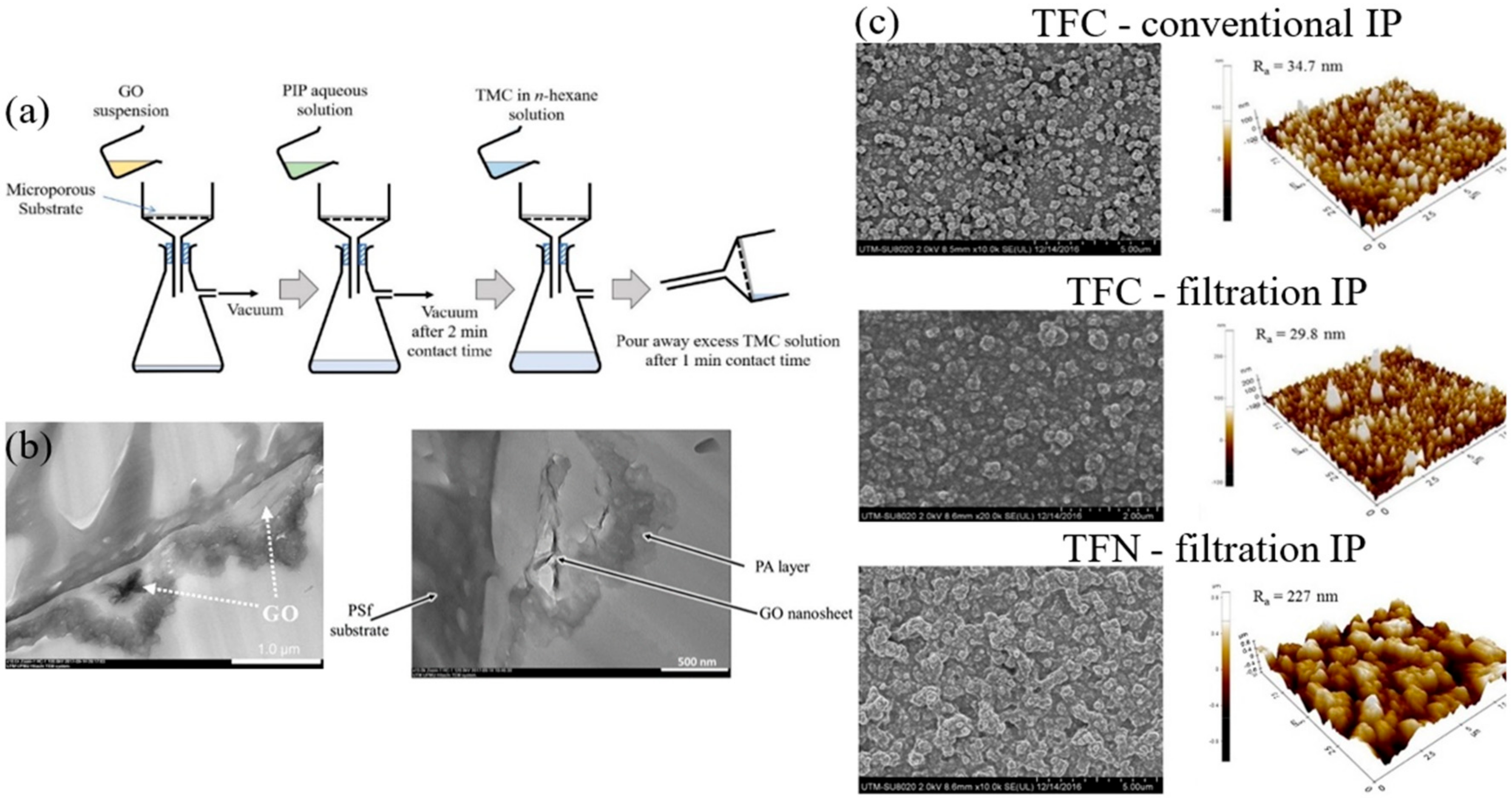
| 2019 | Lai et al. [87] | Filtration of 2 wt % PIP through GO-coated (0.03 g/m2) PSf substrate followed by contact with 0.2 wt % TMC | NF | PWP: 1.80 L/m2·h·bar CA: ~46° Na2SO4 rejection: >95% Flux decline: 24% (tested 0.5 g/L BSA for 4 h) | PWP: 4.13 L/m2·h·bar CA: ~30° Na2SO4 rejection: >95% Flux decline: 1.1% (tested 0.5 g/L BSA for 4 h) | - Smoother PA layer formed - Thin PA layer (53 nm) - Low crosslinking degree (63.5%) |
| 2019 | Zhu et al. [88] | Filtration of 0.2 wt % PIP containing 20.5 µg/cm2 UiO-66-NH2 through PAN substrate followed by contact with 0.15 wt % TMC | NF | Commercial NF membrane (Dow NF270) PWP b: ~12.07 L/m2·h·bar MgSO4 rejection b: >97% | PWP: 30.8 L/m2·h·bar Na2SO4 rejection: 97.5% NaCl rejection: 20% | - Even nanomaterial distribution - Rough PA layer (Ra: 55 nm) - Increased hydrophilicity |
| 2019 | Ren et al. [89] | Filtration of 0.1 wt % PIP containing 0.02 wt % o-POPs through PAN substrate followed by contact with 0.1 wt % TMC | NF | Commercial NF membrane (Dow NF270) PWP b: ~12.07 L/m2·h·bar MgSO4 rejection b: >97% | PWP: 29.9 L/m2·h·bar Na2SO4 rejection: 97.5% | - Even nanomaterial distribution - Crumpled and rough PA layer |
| Year | Authors | Spin IP Conditions | Application | a Performance Comparison | Unique PA Structure | |
|---|---|---|---|---|---|---|
| Conventional IP | Spin-Based IP (Optimum Membrane) | |||||
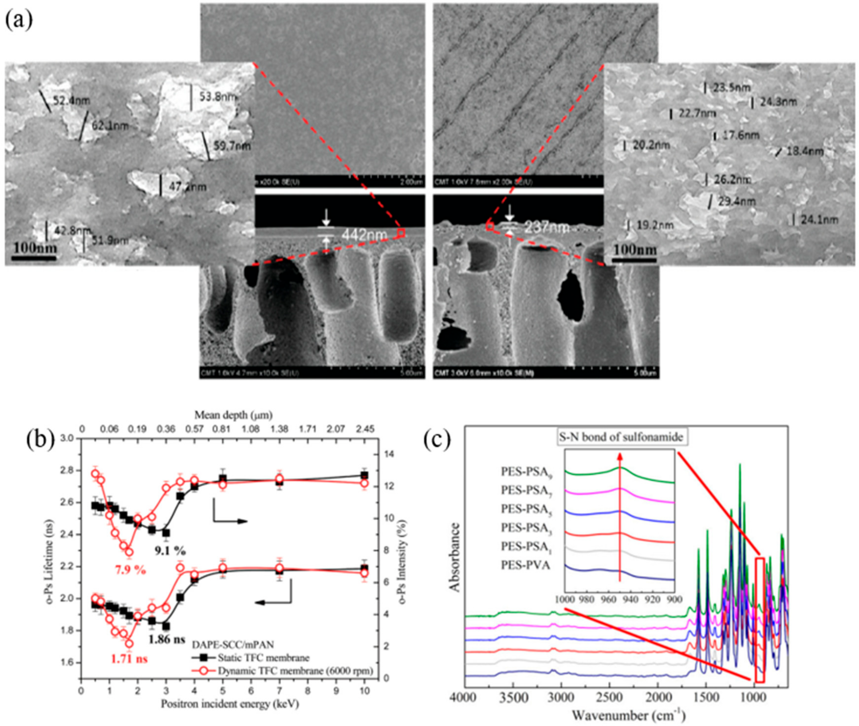
| 2012 | An et al. [95] | Immersion of modified PAN substrate in 0.1 wt % 1,3-diaminopropane followed by spin removal of 0.2 wt % succinyl chloride at 6000 rpm | Pervaporation | Permeate flux b: ~375 g/m2·h Ethanol rejection: 93.6% Ethanol permeability: ~12 × 10−4 g/m.h.MPa CA: ~80° | Permeate flux b: ~660 g/m2·h Ethanol rejection: 99.3% Ethanol permeability: ~1.4 × 10⁻⁴ g/m.h.MPa CA: ~58° | - Parallel lines formed contributed to increased roughness - 46% thinner PA layer - Denser PA layer with smaller cavities |
| 2018 | Yuan et al. [97] | Immersion of PES substrate in 0.5 wt % PIP followed by spinning at 3000 rpm for 40 s. Substrate was then contacted with 0.03 wt % NTSC before drying through spinning, marking the end of 1 cycle (5 cycles is optimal) | RO | Permeability: 2.21 L/m2·h·bar (NaCl) MgSO4 rejection: 82.04% CaCl rejection: 73.5% NaCl rejection: 58.2% CA: ~68° | Permeability: 1.24 L/m2·h·bar (NaCl) MgSO4 rejection: 98.7% CaCl rejection: 98.2% NaCl rejection: 95.7% CA: ~68° | - Linear increase of PSA thickness per layer (2.72 nm/layer) - Minimal change in roughness |
| 2018 | He et al. [98] | Immersion of PES substrate in 0.5 wt % PIP followed by spinning at 3500 rpm for 30 s. Substrate was then contacted with 0.05 wt % TCSP before drying through spinning, marking the end of 1 cycle (5 cycles is optimal) | NF | PWP: 1.49 L/m2·h·bar Na2SO4 rejection: 98.3% MgSO4 rejection: 92.92% | PWP: 3.75 L/m2·h·bar Na2SO4 rejection: 99.8% MgSO4 rejection: 99.37% | - Thinner PSA layer (80 vs. 138 nm) - Minimal change in roughness |
| 2020 | Kang et al. [30] | Spin removal of 0.5 wt % PIP on GO-coated (6 mg/m2) nylon substrate at 600 rpm for 40 s followed by contact with 0.5 wt % TMC | NF | Commercial NF membrane (Dow NF270) PWP c: ~12.07 L/m2·h·bar MgSO4 rejection c: >97% | PWP: ~32 L/m2·h·bar Na2SO4 rejection: ~97% MgSO4 rejection: ~80% | - Extremely thin PA layer (20–35 nm) - Uniform monomer distribution |
| Year | Authors | Ultrasound IP Conditions | Application | a Performance Comparison | a Unique PA Structure | |
|---|---|---|---|---|---|---|
| Conventional IP | Ultrasound-Assisted IP (Optimum Membrane) | |||||
| 2019 | Shen at al. [101] | Immersion of PSf substrate in 2.0 wt % MPD followed by contact with 0.1 wt % TMC under an ultrasonication circumstance (40 kHz and 360 W) | FO | Jv: ~12 L/m2·h Js: ~4.6 g/m2·h | Jv: ~32.5 L/m2·h Js: ~4.3 g/m2·h | - Rougher PA layer formed - Thicker PA layer albeit less dense due to the larger cavities formed - Higher crosslinking degree achieved |
| PRO | Jv: ~25 L/m2·h Js: ~9 g/m2·h | Jv: ~52 L/m2·h Js: ~7.3 g/m2·h | ||||
| RO | PWP: 1.99 L/m2·h·bar NaCl rejection: 94.72% Selectivity (B/A ratio): 0.09 bar | PWP: 3.44 L/m2·h·bar NaCl rejection: 95.92% Selectivity (B/A ratio): 0.07 bar | ||||
| 2019 | Shen at al. [101] | Immersion of PSf substrate in 0.35 wt % PIP followed by contact with 0.15 wt % TMC under an ultrasonication circumstance (40 kHz and 360 W) | NF | PWP: 7.5 L/m2·h·bar NaCl rejection: 27.5% | PWP: 16.3 L/m2·h·bar NaCl rejection:30.0% | n/a |
| 2020 | Shen et al. [102] | Immersion of PSf substrate in 2.0 wt % MPD followed by contact with 0.1 wt % TMC for 1 min under an ultrasonication circumstance (60 kHz and 480 W) | FO | Jv: ~25 L/m2·h Js: ~10.4 g/m2·h CA: 80° FRR b: 83.3% | Jv: ~75 L/m2·h Js: ~8 g/m2·h CA: 55° FRR b: 97.0% | - Rougher (Ra: 90 nm) and thicker PA layer formed - Higher crosslinking degree achieved - PA layer showed increased resistance against gypsum scaling |
| PRO | Jv: ~43 L/m2·h Js: ~19.5 g/m2·h | Jv: ~120 L/m2·h Js: ~12 g/m2·h | ||||
| RO | PWP: 1.9 L/m2·h·bar NaCl rejection: ~94.2% Selectivity (B/A ratio): ~0.1 bar | PWP: 3.6 L/m2·h·bar NaCl rejection: ~97% Selectivity (B/A ratio): ~0.04 bar | ||||
| Year | Authors | Spray IP Conditions | Application | Performance Comparison | Unique PA Structure | |
|---|---|---|---|---|---|---|
| Conventional IP | Spray-Based IP (Optimum Membrane) | |||||
| 2013 | Tsuru et al. [112] | Immersion of PSf substrate in 2 wt % MPD followed by spraying of 0.05 wt % TMC, using airbrush (30 mg/s flow rate for 20 s). Then, 0.1 wt % TMC was allowed to contact with the membrane. | RO | Permeance: ~1.14 L/m2·h·bar (NaCl) NaCl rejection: >95% Glucose rejection: >95% Ethanol rejection: ~40% | Permeance: ~1.98 L/m2·h·bar (NaCl) NaCl rejection: >95% Glucose rejection: >95% Ethanol rejection: ~45% | - Multilayered large and small ridge-and-valley structure formed - Higher crosslinking degree as spray time increases |
| 2017 | Shan et al. [33] | Spraying 1.25 wt % PEI followed by spraying 0.15 wt % TMC on PSf substrate at 2 mL/s flow rate. Each layer was sprayed by 5 s to achieve 5 layers. | NF | Permeance a: 5.3 L/m2·h·bar | Permeance a: 124.6 L/m2·h·bar Humic acid rejection: 99.3% | - Extremely thin PA layer formed (25 nm) |
| 2019 | Morales-Cuevas et al. [113] | Brushing aqueous solution (0.25 wt % PIP, 0.25 wt % PVA and 0.5 wt % NaOH) onto PSf substrate followed by the spraying 1 wt % TMC solution (5 mL) | NF | PWP: 1.23 L/m2·h·bar Na2SO4 rejection: ~99% NaCl rejection: ~20% | PWP: 1.87 L/m2·h·bar Na2SO4 rejection: 99% NaCl rejection: ~40% | - Smoother PA layer (Average roughness: 48 nm) |
| Year | Authors | Electrospray IP Conditions | Application | a Performance Comparison | a Unique PA Structure | |
|---|---|---|---|---|---|---|
| Conventional IP | Electrospray IP (Optimum Membrane) | |||||
| 2018 | Chowdhury et al. [31] | Electrospraying 0.083 wt % MPD and 0.05 wt % TMC onto a PAN substrate-mounted rotating drum (flow rate: 5 mL/h, tip to drum distance: 2.5–5 cm and rotating speed: 20 rpm) | RO | Commercial RO membrane (SW30XLE) PWP b: 0.7 L/m2·h·bar NaCl rejection b: 99.7% RMS: ~84 nm | PWP: 14.7 L/m2·h·bar NaCl rejection: 94% RMS: 13.4 nm | - Extremely thin PA layer (25 nm) with high repeatability - Extremely smooth PA layer |
| 2018 | Ma et al. [126] | Electrospraying 2.0 wt % MPD and 0.2 wt % TMC onto a PES substrate-mounted rotating drum (flow rate: 1.2 mL/h, tip to drum distance: 6 cm and rotating speed: 100 rpm) | RO | PWP: 0.55 L/m2·h·bar CA: 53.3° | PWP: 1.7 L/m2·h·bar NaCl rejection: 84% Na2SO4 rejection: 94% CA: 72.0° | - Linear PA growth rate (~1 nm/min) - Extremely smooth (Ra: 1.2 nm) and thin PA layer (~30 nm) |
| 2020 | Yang et al. [127] | Electrospraying 0.24 wt % PIP and 0.08 wt % TMC onto a PES substrate-mounted rotating drum (flow rate: 1.2 mL/h, tip to drum distance: 6 cm and rotating speed: 80 rpm) | NF | PWP: 4.4 L/m2·h·bar Na2SO4 rejection: 98.1% | PWP: 16.6 L/m2·h·bar Na2SO4 rejection: 95.5% | - Linear PA growth rate (~0.33 nm/min) - Extremely smooth (Ra: 15.3 nm) and thin PA layer (22 nm) - Lamellar PA layer that can provide extra water channels |
| Year | Authors | Reverse IP Conditions | Application | a Performance Comparison | Unique PA Structure | |
|---|---|---|---|---|---|---|
| Conventional IP | Reverse IP (Optimum Membrane) | |||||
| 2014 | Wang et al. [131] | Immersion of substrate (modified PAN on polyethylene terephthalate (PET)) into 0.1 wt % TMC followed by contacting with 3 wt % PIP. | NF | Permeability: 7.1 L/m2·h·bar (MgSO4) MgSO4 rejection: ~99% MgCl2 rejection: ~99% | Permeability: 9.0 L/m2·h·bar (MgSO4) MgSO4 rejection: ~98% MgCl2 rejection: ~97% | - Dense part of PA layer was formed on the top instead of near the substrate as in conventional IP |
| 2016 | Mahdavi and Moslehi [129] | Immersion of substrate (PET) into 0.3 wt % TMC followed by contacting with 1 wt % PPD. | NF | Commercial NF membrane (Sepro NF 2A) [78] PWP: 10.1 L/m2·h·bar NaCl rejection: 24.8% | PWP: 6.8 L/m2·h·bar NaCl rejection: 78% Na2SO4 rejection: 93% | - Smooth PA layer without defects formed on both electrospun and casted substrate |
| 2018 | Qanati et al. [130] | Immersion of substrate (polyvinylidene fluoride) into 0.05 wt % 1,2,4,5-benzene tetracarbonyl chloride and 0.05 wt % TMC followed by contacting with 2 wt % ethylenediamine and 2 wt % triethylamine. | RO | Commercial RO membrane (Dow SW30XLE) PWP b: 0.7 L/m2·h·bar NaCl rejection b: 99.7% | PWP: 2.38 L/m2·h·bar NaCl rejection: 94.8% NaCl rejection after chlorine test: 93.4% | - Polyimide selective layer shows similar structure as typical NF PA layer |
| 2019 | Shen et al. [132] | Immersion of substrate (gelatin on PAN) into 0.2 wt % TMC followed by contacting with 1 wt % PIP | NF | Commercial NF membrane (Dow NF270) PWP b: ~12.07 L/m2·h·bar MgSO4 rejection b: >97% | PWP: 33.7 L/m2·h·bar MgSO4 rejection: 97.5% NaCl rejection: 14.3% | -Ultrathin PA layer formed -Crumpled, defect-free PA observed |
| 2019 | Song et al. [80] | Immersion of substrate (PSf) into 0.1 wt % TMC followed by contacting with 2 wt % MPD | RO | Permeability: ~1.55 L/m2·h·bar (NaCl) NaCl rejection: ~99% | Permeability: ~0.75 L/m2·h·bar (NaCl) NaCl rejection: ~95.7% | -Crater-like/porous structures formed instead of typical ridge-and-valley structures -Smooth PA (Average roughness: 23 nm) |
| Technique | Advantages | Disadvantages |
|---|---|---|
| Support-free IP | - High scalability (DSC and IFIP) - High precision (automated DSC and IFIP) - Able to form PA at very low monomer concentration | - Difficult to transfer/attach PA film onto substrate |
| Filtration-based IP | - Suitable to deposit 2D nanosheets on the substrate - No leaching of nanomaterials during filtration - Nanomaterials can be well embedded within PA layer with good stability | - Not suitable for depositing 3D nanomaterials with particle size much smaller than substrate pore size - Precise control of PA layer thickness is rather difficult - Low scalability |
| Spin-based IP | - Rapid process - Able to produce highly uniform PA layer | - Low scalability - Chemical/nanomaterials wastage is unavoidable during spinning - Require precise control of shearing force |
| Ultrasound-based IP | -Formation of nanovoids within PA layer that could improve water flux | - Limited studies |
| Spray-based IP | - High scalability - Minimum use of chemicals/nanomaterials - Relatively fast process - Precise control of PA layer thickness | - Lack of long-term membrane stability evaluation - Lack of economic analysis |
| Electrospray-based IP | - Moderate scalability - Minimum use of chemicals - Precise control of PA layer thickness (at nm scale) | - Slow process (>1 h) - Relatively high energy requirement (high voltage equipment) - Difficult to produce large-sheet of membrane |
| Reverse IP | - Suitable for hydrophobic substrate | - Difficult to form defect-free TFC membrane, using widely used substrate (e.g., PSf and PAN) |
Publisher’s Note: MDPI stays neutral with regard to jurisdictional claims in published maps and institutional affiliations. |
© 2020 by the authors. Licensee MDPI, Basel, Switzerland. This article is an open access article distributed under the terms and conditions of the Creative Commons Attribution (CC BY) license (http://creativecommons.org/licenses/by/4.0/).
Share and Cite
Seah, M.Q.; Lau, W.J.; Goh, P.S.; Tseng, H.-H.; Wahab, R.A.; Ismail, A.F. Progress of Interfacial Polymerization Techniques for Polyamide Thin Film (Nano)Composite Membrane Fabrication: A Comprehensive Review. Polymers 2020, 12, 2817. https://doi.org/10.3390/polym12122817
Seah MQ, Lau WJ, Goh PS, Tseng H-H, Wahab RA, Ismail AF. Progress of Interfacial Polymerization Techniques for Polyamide Thin Film (Nano)Composite Membrane Fabrication: A Comprehensive Review. Polymers. 2020; 12(12):2817. https://doi.org/10.3390/polym12122817
Chicago/Turabian StyleSeah, Mei Qun, Woei Jye Lau, Pei Sean Goh, Hui-Hsin Tseng, Roswanira Abdul Wahab, and Ahmad Fauzi Ismail. 2020. "Progress of Interfacial Polymerization Techniques for Polyamide Thin Film (Nano)Composite Membrane Fabrication: A Comprehensive Review" Polymers 12, no. 12: 2817. https://doi.org/10.3390/polym12122817