Polyaniline Nanotubes/Carbon Cloth Composite Electrode by Thermal Acid Doping for High-Performance Supercapacitors


1
Engineering Technology and Materials Research Center, China Academy of Transportation Sciences, Beijing 100029, China
2
Department of Material Engineering, Jiangsu University of Technology, Changzhou 213001, China
*
Author to whom correspondence should be addressed.
Polymers 2019, 11(12), 2053; https://doi.org/10.3390/polym11122053
Submission received: 21 November 2019
/
Revised: 7 December 2019
/
Accepted: 9 December 2019
/
Published: 11 December 2019
(This article belongs to the Special Issue Polymer-Based Soft Electronics)
Abstract
:Carbon materials have been widely used in designing supercapacitors (SCs) but the capacitance is not ideal. Herein, we synthesize polyaniline (PANI) nanotubes on the basis of a carbon cloth (CC) through a one-step self-degradation template method, and fabricate a CC@PANI NTs-H (CC@PANI nanotubes doping at high temperature) composite electrode by thermal acid doping. The CC@PANI NTs-H electrode obviously exhibits better electrochemical performance with a gravimetric capacitance of 438 F g−1 and maintains 86.8% after 10,000 cycles than the CC@PANI NTs-R (CC@PANI nanotubes doping at room temperature) electrode. Furthermore, we assemble a flexible solid state supercapacitor (FSSC) device with the as-prepared CC@PANI NTs-H composite electrodes, showing good flexibility and outstanding electrochemical performances with a high gravimetric capacitance of 247 F g−1, a large energy density of 21.9 Wh kg−1, and a capacitance retention of 85.4% after 10,000 charge and discharge cycles. Our work proposes a novel and easy pathway to fabricate low-cost FSSCs for the development of energy storage devices.

1. Introduction
With ever-increasing demands for efficient energy, considerable efforts have been made to design and fabricate new energy conversion/storage devices [1]. Supercapacitors (SCs), as a new class of energy storage device, have received much attention over the past years due to their wide working temperature range, high power-delivery capability, fast charge-discharge rate and long cycle-stability [2]. Electrical double-layer capacitors (EDLCs) usually based on carbon materials including graphene and carbon nanotubes, but the specific capacitances are typically less than 100 F g−1, which largely limits their applications [2,3]. Pseudocapacitors, characterized by a series of fast and reversible redox reactions or Faradic charge transfer, exhibit a larger capacitance and energy density compared with EDLCs [4]. However, due to volumetric swelling/shrinking in the charging and discharging process, pseudocapacitive materials including conducting polymers and transition metal compounds often show poor cyclic stability [4,5].
It is a good strategy to obtain the synergetic effect of EDLC and pseudocapacitive materials in the field of designing a composite electrode [6]. Shao et al. [7] synthesized a hierarchical polypyrrole (PPy) @ layered double hydroxides (LDHs) core-shell arrays to fabricate flexible solid state supercapacitors (FSSCs), the cycling stability was improved by 15.4% after 20,000 cycles. Chen et al. [8] manufactured a composite electrode based on spherical PPy nanoparticles growing on the reduced graphene oxide (RGO)-coated carbon cloth (CC), which showed high capacitance and energy density. Yun et al. [9] assembled a wearable and all-transparent supercapacitor, consisting of an Au/Ag core-shell nanowire-embedded polydimethylsiloxane (PDMS) and WO3 nanotube/PEDOT: PSS thin layer, exhibiting a powerful ability of charge storage and excellent flexibility to wear.
PPy is a frequently-used conducting polymer, but there is a difference between theoretical prediction of the capacitance and practical value when it is used for supercapacitors [10]. As another important conducting polymer, polyaniline (PANI) is a highly promising electrode material for a supercapacitor due to its high pseudocapacitance, but its poor cycling stability has resulted in people making much more effort to enhance the electrochemical property in recent years [11,12,13,14]. Du et al. [15] used celery as biomass carbon precursor to prepare nitrogen-doped hierarchical porous carbon materials by combining with PANI, also displaying high specific capacitance of 402 F g−1 and an outstanding cycling stability. Lee et al. [16] designed a new strategy using aniline tetramers loaded on graphene oxide (AT–GO), the capacitance can reach 769 F g−1 at 1 A g−1 and still remains 581 F g−1 at 60 A g−1.
In this study, we used CC as a carbon-based substrate and grew PANI nanotubes through a one-step self-degradation template method, then activated a CC@PANI NTs composite by thermal acid doping. CC@PANI NTs-H (doping at a high temperature) composite electrodes obviously exhibit better electrochemical performances than CC and CC@PANI NTs-R (doping at room temperature) composite electrodes. Furthermore, CC@PANI NTs-H composite electrodes were used to assemble symmetric FSSCs, the gravimetric capacitance is 247 F g−1 and the maximum energy density reaches 21.9 Wh kg−1, meanwhile showing good cycling stability and favorable flexibility.
2. Experimental
2.1. Materials
Carbon cloth (CC) was purchased from Taiwan Carbon Energy technology company. Polyvinyl alcohol (PVA) was bought from Shanghai Qiangshun chemical company (Shanghai, China). Acetone, ethanol, aniline, methyl orange (MO), FeCl3.6H2O, (NH4)2S2O8, HNO3, H2SO4 and H3PO4 were purchased from Shanghai Lingfeng chemical company (Shanghai, China). Separator (NKK TF4535) was provided by Koji paper industry corporation of Japan (Tokyo, Japan).
2.2. Activation of CC
CC was cut into slices of the size of 1.5 × 1 cm2, in which the working area was 1 cm2 and the extra part was used as the current collector. Then CC slices were cleaned by acetone, ethanol and deionized water in an ultrasonic bath, in turn. CC was immersed into a 5 M HNO3 solution for 16 h, and then washed with deionized water. Finally, the activated CC was dried at 50 °C for 4 h.
2.3. Preparation of CC@PANI NTs
The as-prepared CC was stirred in methyl orange (MO) solution (5 mM, 20 mL) for 0.5 h, and then 2.5 mmol FeCl3.6H2O was added into the solution to form a FeCl3–MO template [17]. After 0.5 h, aniline monomer (2.5 mmol, 228 μL) was added into the system and stirred for another 24 h at room temperature. Finally, the CC@PANI NTs was obtained after washing by deionized water and ethanol.
2.4. Thermal Acid Doping of CC@PANI NTs
The as-synthesized CC@PANI NTs was immersed into 5 M H2SO4, and then kept in a Teflon autoclave at 100 °C for 4 h. After the reaction, the CC@PANI NTs was washed with deionized water and dried at 50 °C, named CC@PANI NTs-H. Meanwhile, we also carried out a control group to demonstrate the effect of thermal acid doping, that was doping in 5 M H2SO4 at an ambient temperature, named CC@PANI NTs-R.
2.5. Assembly of FSSCs
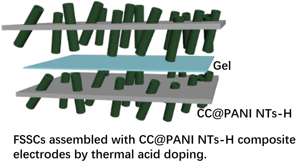
The PVA-H3PO4 gel electrolyte was prepared as follows: 3 g PVA and 30 mL deionized water were mixed and stirred at 90 °C until the gel became transparent, and cooled to room temperature [18]. Then 3 g H3PO4 was dropwise added into the gel under stirring for several hours to obtain the PVA-H3PO4 gel. The CC@PANI NTs-H electrodes were soaked into a PVA-H3PO4 gel for 10 min and then assembled together with a separator (NKK TF4535, 35 μm) to prepare FSSCs devices. The assembly devices were solidified at ambient temperature for electrochemical measurements.
2.6. Characterization
The electrodes were characterized by a field-emission scanning electron microscope (FE-SEM, Sigma 500, Carl Zeiss, Jena, Germany), transmission electron microscopy (TEM, JEM-2100, Jeol, Tokyo, Japan), Fourier transform infrared spectrometry analyzer (FTIR, Nicolet 6700, Thermo Scientific, Waltham, MA, USA), Raman spectroscopy (XploRA, HORIBA, Irvine, CA, USA) and x-ray photoelectron spectroscopy (XPS, PHI 5000CESCA, Perkin-Elmer, Waltham, MA, USA). Electrochemical performances such as cyclic voltammetry (CV), galvanostatic charge/discharge (GCD) and electrochemical impedance spectroscopy (EIS), were measured on an electrochemical workstation (Chenhua, CHI760E, Shanghai, China). The as-fabricated composite electrodes were tested in a three-electrode system with a 1 M H2SO4 solution as an electrolyte, Hg/Hg2Cl2 electrode and Pt wire were used as the reference and counter electrodes, respectively. The assembled FSSC devices were tested in a two-electrode system.
2.7. Calculations
The as-fabricated electrodes were measured in the three-electrode system. The areal capacitance (CA: mF cm−2) and gravimetric capacitance (Cg: F g−1) were calculated from the GCD curves according to the following Equations:
where I (A) is the discharging current, Δt (s) is the discharging time, ΔV (V) is the voltage window, S (cm2) is the working area of electrodes, and m (g) is the mass loading of active materials on CC.
CA = 1000(IΔt)/(ΔVS)
Cg = (IΔt)/(ΔVm)
In addition, the FSSC devices were measured in a two-electrode system. The areal capacitance (CA: mF cm−2) and gravimetric capacitance (Cg: F g−1) of the FSSCs were also calculated from GCD curves according to the following Equations:
where I (A) is the discharging current, Δt (s) is the discharging time, ΔV (V) is the voltage window, S (cm2) is the working area of FSSCs devices, and mt (g) is total mass loading of the single electrode in FSSCs devices.
CA = 1000(IΔt)/(ΔVS)
Cg = (IΔt)/2(ΔVmt)
Energy density (E: Wh kg−1) and power density (P: W kg−1) of devices were calculated according to the following Equations:
where Cg (F g−1) is gravimetric capacitance of FSSCs, ΔV (V) is the voltage window and Δt (s) is the discharging time.
E = (CgΔV2)/(4 × 3.6)
P = 3600 × E/Δt
3. Results and Discussion
3.1. Mechanism and Morphologies of CC@PANI NTs Composite Electrodes
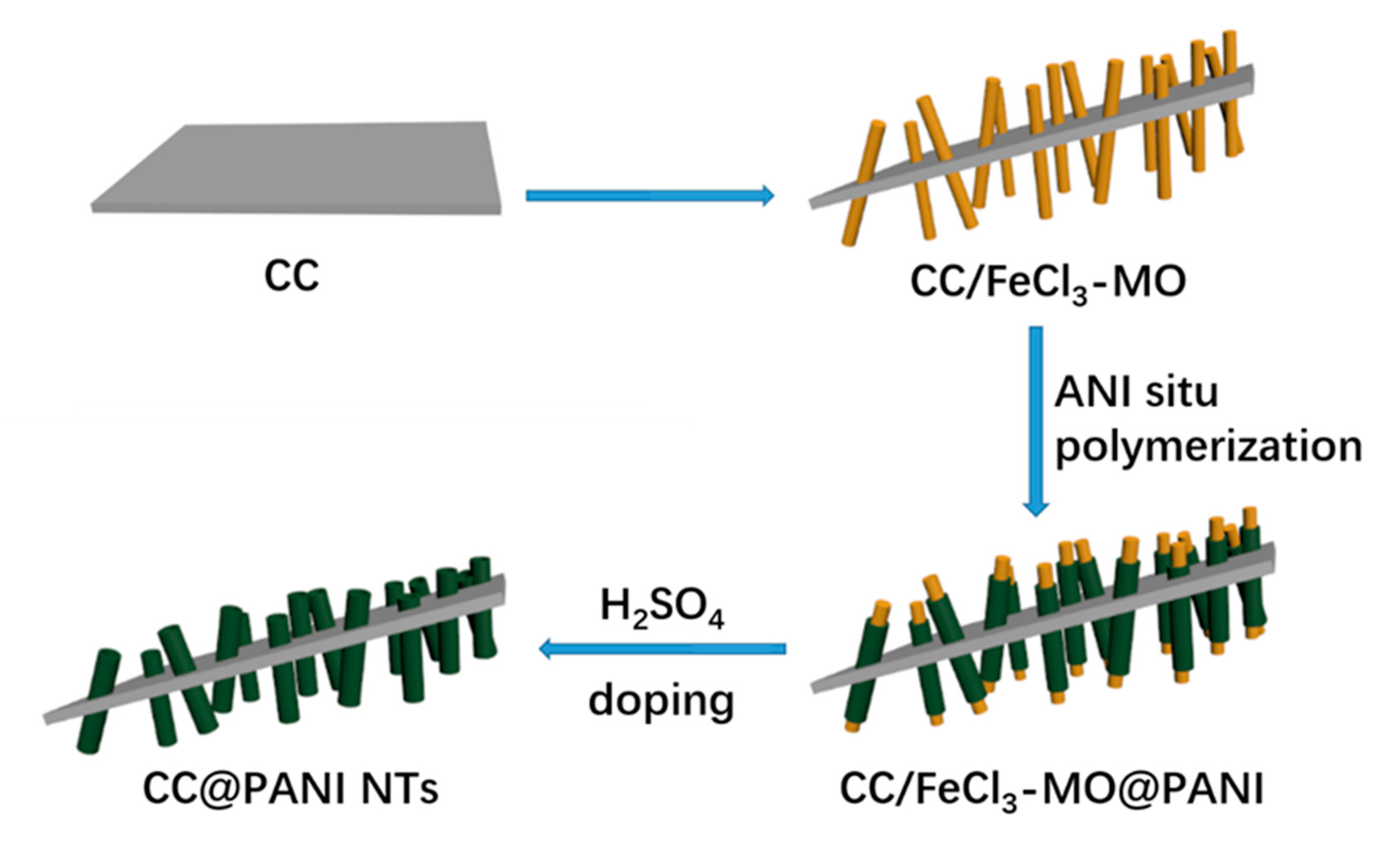
The fabrication process of CC@PANI NTs composites is schematically illustrated in Figure 1. The CC substrate is first activated in HNO3, and then FeCl3 is reacted with MO on the surface of CC substrate to form nano-fibrous templates (FeCl3–MO). Additionally, aniline molecules are in situ polymerized under the initiating action of ammonium persulfate, and then grown on the surface of FeCl3–MO fibrous templates. After that, the FeCl3–MO fibrous templates are washed by deionized water, only PANI NTs are left. Finally, CC@PANI NTs are obtained by doping with H2SO4 at room or high temperature, named CC@PANI NTs-R or CC@PANI NTs-H.
The microstructures and morphologies of CC, PANI NTs and CC@PANI NTs-H composite materials are revealed by FE-SEM and TEM, as shown in Figure 2. Figure 2a shows the surface of CC is smooth and neat. However, a number of nanofibers are grown on the surface of CC due to the in situ polymerization of aniline, as shown in Figure 2b. To clearly observe the structure of PANI fibers in CC@PANI NTs composite, we amplified PANI NTs and characterized by FE-SEM and TEM (Figure 2c,d). Figure 2c shows that the diameter of PANI NTs is about 200–300 nm. Figure 2d demonstrates the microfiber is hollow tubular structure.
3.2. Characterizations of CC@PANI NTs Composite Electrodes
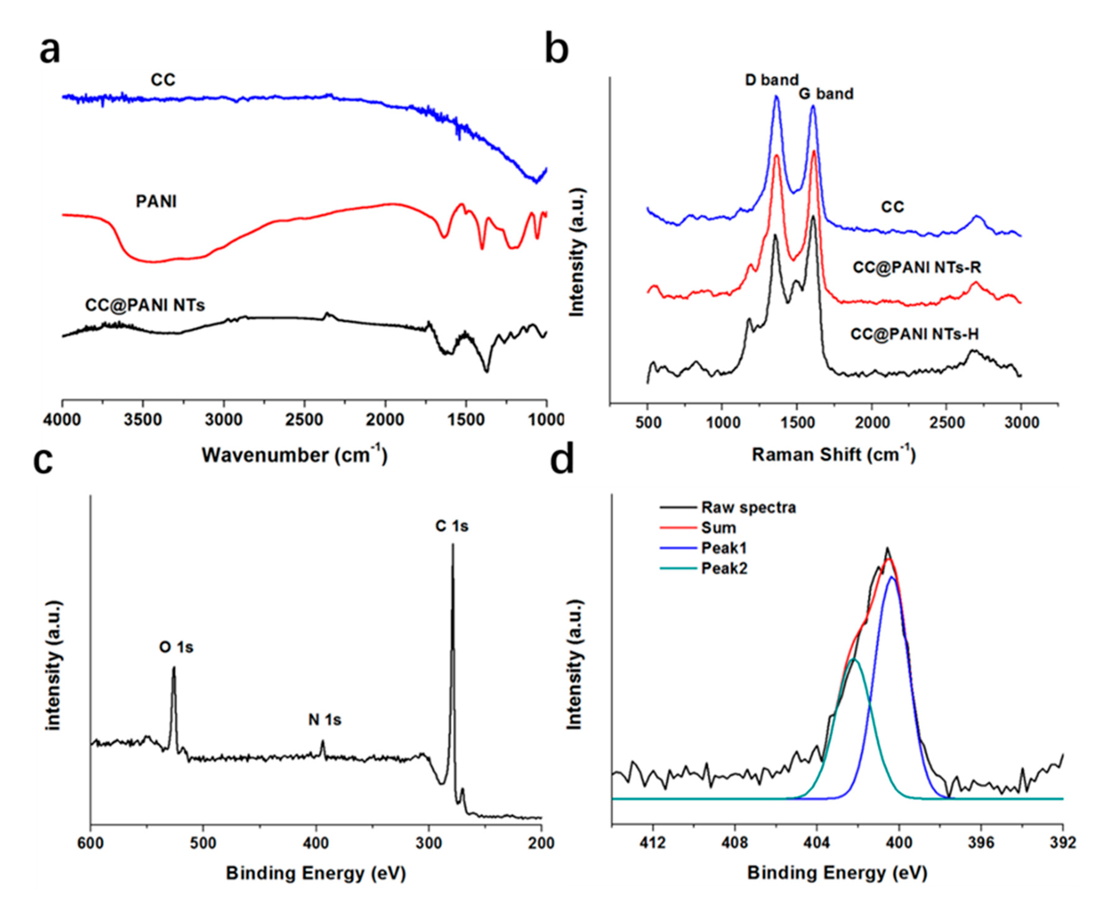
Figure 3a shows Fourier Transform Infrared Spectrometer (FTIR) spectrums of the CC, PANI and CC@PANI NTs-H composite. From Figure 3a, almost no characteristic peak can be found in the spectrum of CC because of few functional groups. Compared with CC, the characteristic peaks of PANI at 1578 cm−1 (C=C stretching vibration in Quinone), 1500 cm−1 (C=C stretching vibration in benzene ring), 1312 cm−1 (C–N stretching vibration) and 1132 cm−1 (N=Q=N stretching vibration), all appear but shift to low frequency range due to the effect of H2SO4 doping, in the spectrum of the CC@PANI NTs-H composite [19]. Gizdavic-Nikolaidis et al. [20] studied the FTIR spectrums of PANI doped H2SO4, an obvious shift was observed with increasing concentration of H2SO4 due to the form of depronated band.
Raman spectra in Figure 3b shows two obvious characteristic peaks at 1358 and 1604 cm−1, which assign disordered sp3 carbon (D band) and graphitic sp2 (G band) [21]. The intensity ratio of D and G band (ID/IG) was also calculated, 1.08 for CC, 0.98 for CC@PANI NTs-R and 0.88 for CC@PANI NTs-H, respectively. The ratio of amorphous carbon is high in CC, while the graphitic degree is enhanced after thermal doping in CC@PANI NTs-H. The existence of H2SO4 can increase ordered structure of carbon and conjugation length of PANI, which may improve the conductivity of PANI and promote transfer of ions and electrons [22].
We also analyzed the composition of the CC@PANI NTs-H by x-ray photoelectron spectroscopy (XPS), the results are displayed in Figure 3c,d. There are three sharp peaks at 532.8, 400.6 and 285.3 eV in Figure 3c, which represent O 1s, N 1s and C 1s, respectively. N element is mainly from PANI, so we analyzed N 1s spectra by fitting, as shown in Figure 3d. The split peak1 at 400.3 eV and peak 2 at 402.2 eV can be ascribed to the ground state N–H and protonated nitrogen species (N+) [23], respectively. The amount of intrinsic oxidation state (N+) of PANI equals to the value of (−N = +N+), which can promote protons donation and electrons transfer [22].
3.3. Electrochemical Performances of CC@PANI NTs Composite Electrodes
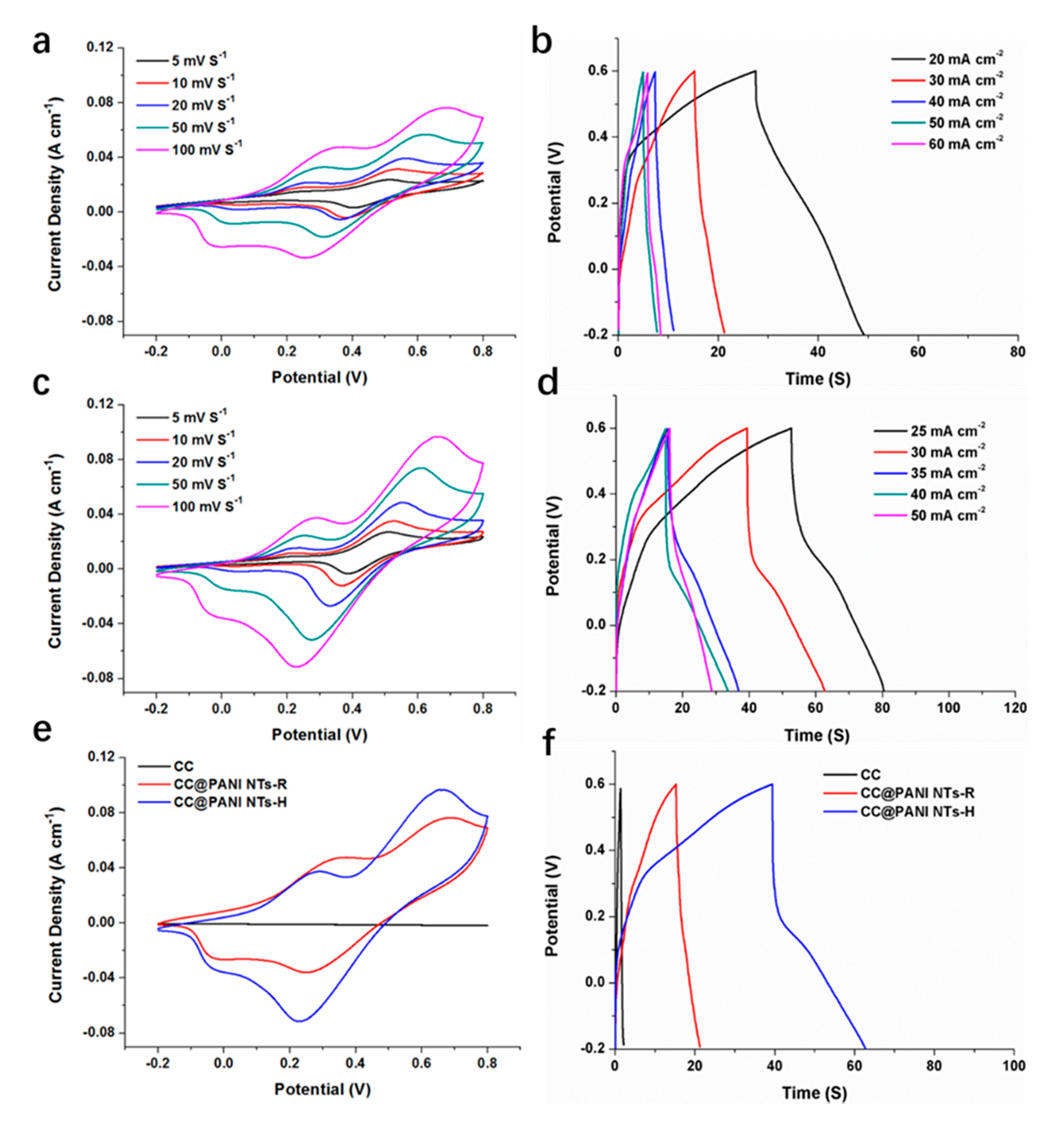
Next we measured the electrochemical performances of CC, CC@PANI NTs-R and CC@PANI NTs-H composite electrodes in 1 M H2SO4 electrolyte by the three-electrode setup. The mass loading of active materials on the electrode is about 2 mg cm−2. Figure 4a,c reflect CV curves of CC@PANI NTs-R and CC@PANI NTs-H electrodes at different scan rates. As shown in Figure 4a,c, the area of close curves gets larger with the increase of scan rate, while the shape of CV curves exhibit Faradic redox peaks, suggesting typical pseudocapacitive behaviors of both CC@PANI NTs-R and CC@PANI NTs-H electrodes. In addition, the GCD curves shown in Figure 4b,d also exhibit obvious pseudocapacitive behaviors, especially CC@PANI NTs-H electrode. Figure 4e,f shows comparison among CC, CC@PANI NTs-R and CC@PANI NTs-H. CC shows little area in the CV curve, correspondingly, its discharging time is also quite short, demonstrating the specific capacitance of CC is small. CC@PANI NTs-H electrode shows a larger area than CC@PANI NTs-R electrodes in Figure 4e, and the discharging time of former is also longer than latter in Figure 4f. The maximum gravimetric capacitance of CC@PANI NTs-H is 438 F g−1, which are larger than that of CC@PANI NTs-R (276 F g−1), respectively. The values are superior to most similar electrodes [18,24,25,26,27,28], as shown in Table 1. The better electrochemical performances of the CC@PANI NTs-H electrode in comparison with CC@PANI NTs-R can be attributed to acid doping at high temperature, which promotes the ordered structure of PANI and provides more sufficient protons [29].
Figure 5a shows the Nyquist plots of composite electrodes, and the inset in Figure 5b reveals the high frequency region of curves. The intercept at the real axis in the high frequency region represents the equivalent series resistance (ESR). The ESR of CC@PANI NTs-H electrode (1.64 Ω) is much smaller, compared with CC@PANI NTs-R (2.10 Ω). The results reflect a low-resistant property in CC@PANI NTs-H, suggesting its low diffusion hindrance for ions and electrons [30]. Figure 5b reveals the cycling performance of the CC@PANI NTs-H electrode, the capacitance can still maintain 86.8% after 10,000 charge and discharge cycles, which demonstrates that the poor cycling stability of PANI has been improved a lot.
3.4. Electrochemical Performances of Assembled FSSCs Device from CC@PANI NTs-H Flexible Electrodes
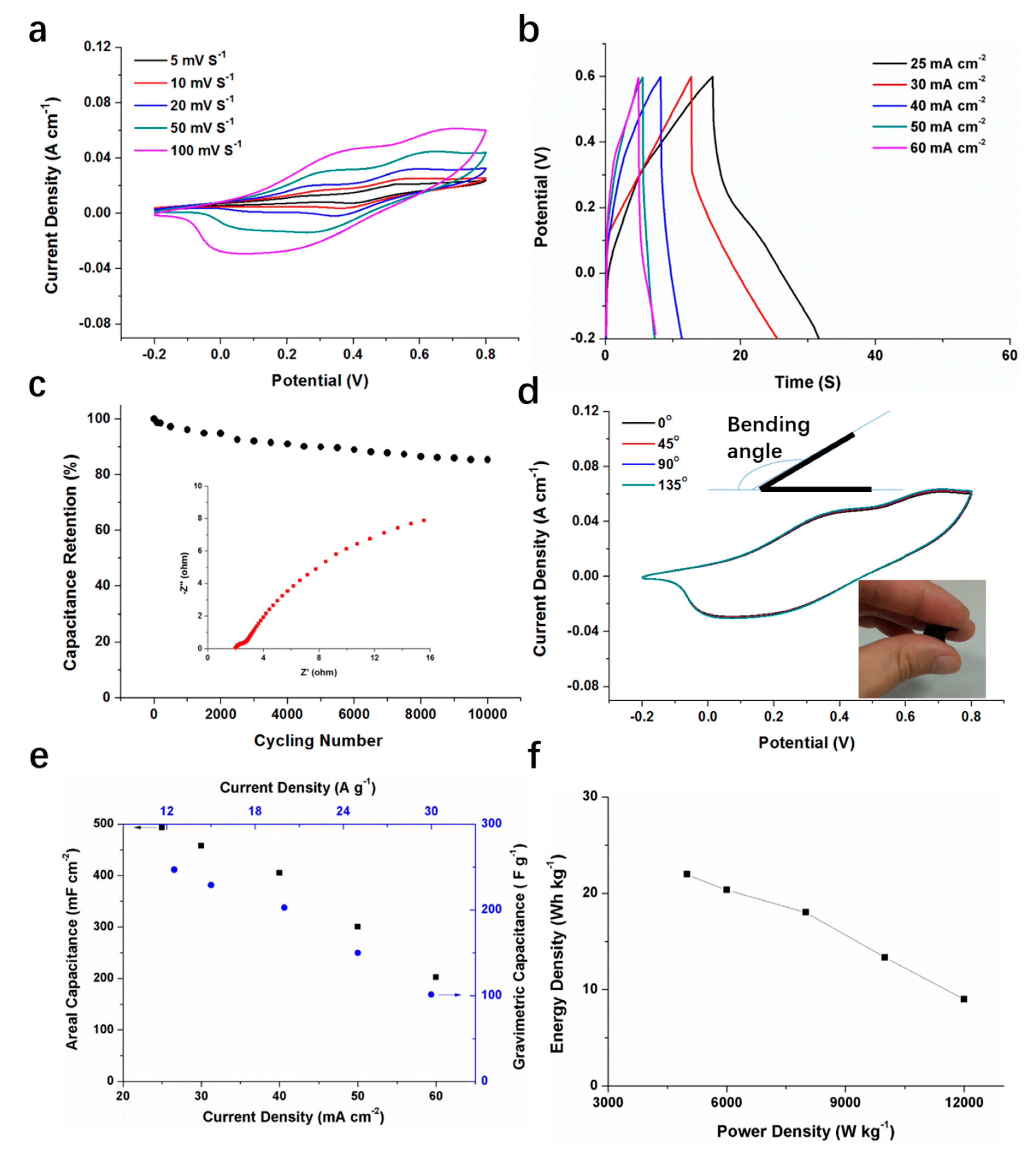
The symmetric FSSC was assembled with two CC@PANI NTs-H composite electrodes, the working area is 1 cm2 and the thickness of the assembled device is 0.08 cm. The electrochemical performances of the device have been studied. From Figure 6a, redox peaks are observed in CV curves of CC@PANI NTs-H FSSC, showing pseudocapacitive characteristics. Figure 6b shows the GCD curves of the device at different current densities, the asymmetrical triangle profile also suggests pseudocapacitive behaviors. The ions and electrons can easily transport in the CC@PANI NTs-H material and penetrate the gel electrolyte. As shown in Figure 6c, the capacitance retention maintains 85.4% after 10,000 cycles, indicating good cycling stability and a sturdy electrode structure. Figure 6d shows the CV curves under different bending angles at the scan rate of 100 mV s−1, the coincident shapes under the bending angles of 45°, 90° and 135° demonstrates good flexibility of the CC@PANI NTs-H FSSCs.
Furthermore, we calculated the areal and gravimetric specific capacitances, and listed the plots of energy density to power density. As shown in Figure 6e, the maximum areal and gravimetric specific capacitances are 494 mF cm−2 and 247 F g−1, respectively. From Figure 6f, the CC@PANI NTs-H FSSC exhibits a high energy density from 21.9 Wh kg−1 (at the power density of 5.0 × 10³ W kg−1) to 9 Wh kg−1 (at the power density of 1.2 × 10⁴ W kg−1). The values are comparable with other congeneric FSSCs devices [31,32,33,34,35], as can be seen in Table 2.
4. Conclusions
In conclusion, we fabricated a novel CC@PANI NTs-H flexible electrode through a one-step self-degradation template method and thermal acid doping process, the gravimetric capacitance can reach 438 F g−1 and maintain 86.8% after 10,000 cycles, the unique thermal acid doping method obviously exhibits better electrochemical performances than doping at room temperature. Moreover, we assembled a FSSC device with the as-prepared CC@PANI NTs-H composite electrodes, delivering favorable flexibility and excellent electrochemical performances with a high gravimetric capacitance of 247 F g−1, a large energy density of 21.9 Wh kg−1, and a capacitance retention of 85.4% after 10,000 cycles. This study provides a new direction for fabricating a low-cost and high-performance FSSCs in the energy storage field.
Author Contributions
Methodology, J.H.; data curation, D.W. and J.C.; writing, Z.Y.; funding acquisition, Z.Y.
Funding
This research was funded by [the Doctor Shuangchuang Foundation of Jiangsu Province], grant number [KYQ19027].
Conflicts of Interest
The authors claim that the researchers in this study have no conflicts of interest.
References
- Ou, X.; Li, Q.; Xu, D.; Guo, J.; Yan, F. In situ growth of MnO2 nanosheets on n-doped carbon nanotubes derived from polypyrrole tubes for supercapacitors. Chem. Asian J. 2018, 13, 545–551. [Google Scholar] [CrossRef] [PubMed]
- Dai, L.; Chang, D.W.; Baek, J.B.; Lu, W. Carbon nanomaterials for advanced energy conversion and storage. Small 2012, 8, 1130–1166. [Google Scholar] [CrossRef] [PubMed]
- Peng, H.; Yao, B.; Wei, X.; Liu, T.; Kou, T.; Xiao, P.; Zhang, Y.; Li, Y. Pore and heteroatom engineered carbon foams for supercapacitors. Adv. Energy Mater. 2019, 9, 1803665. [Google Scholar] [CrossRef]
- Huang, Y.; Li, H.; Wang, Z.; Zhu, M.; Pei, Z.; Xue, Q.; Huang, Y.; Zhi, C. Nanostructured polypyrrole as a flexible electrode material of supercapacitor. Nano Energy 2016, 22, 422–438. [Google Scholar] [CrossRef]
- Kandasamy, S.K.; Kandasamy, K. Recent advances in electrochemical performances of graphene composite (graphene-polyaniline/polypyrrole/activated carbon/carbon nanotube) electrode materials for supercapacitor: A review. J. Inorg. Organomet. Polym. Mater. 2018, 28, 559–584. [Google Scholar] [CrossRef]
- Xun, Z.; Ni, S.; Gao, Z.; Zhang, Y.; Gu, J.; Huo, P. Construction of polymer electrolyte based on soybean protein isolate and hydroxyethyl cellulose for a flexible solid-state supercapacitor. Polymers 2019, 11, 1895. [Google Scholar] [CrossRef] [Green Version]
- Shao, M.; Li, Z.; Zhang, R.; Ning, F.; Wei, M.; Evans, D.G.; Duan, X. Hierarchical conducting polymer@clay core-shell arrays for flexible all-solid-state supercapacitor devices. Small 2015, 11, 3530–3538. [Google Scholar] [CrossRef]
- Chen, Z.; Liao, W.; Ni, X. Spherical polypyrrole nanoparticles growing on the reduced graphene oxide-coated carbon cloth for high performance and flexible all-solid-state supercapacitors. Chem. Eng. J. 2017, 327, 1198–1207. [Google Scholar] [CrossRef]
- Yun, T.G.; Park, M.; Kim, D.H.; Kim, D.; Cheong, J.Y.; Bae, J.G.; Han, S.M.; Kim, I.D. All-transparent stretchable electrochromic supercapacitor wearable patch device. ACS Nano 2019, 13, 3141–3150. [Google Scholar] [CrossRef]
- Wang, K.; Wu, H.; Meng, Y.; Wei, Z. Conducting polymer nanowire arrays for high performance supercapacitors. Small 2014, 10, 14–31. [Google Scholar] [CrossRef]
- Feng, E.; Peng, H.; Zhang, Z.; Li, J.; Lei, Z. Polyaniline-based carbon nanospheres and redox mediator doped robust gel films lead to high performance foldable solid-state supercapacitors. New J. Chem. 2017, 41, 9024–9032. [Google Scholar] [CrossRef]
- Phattharasupakun, N.; Wutthiprom, J.; Ma, N.; Suktha, P.; Sawangphruk, M. High-performance supercapacitors of N-doped graphene aerogel and its nanocomposites with manganese oxide and polyaniline. J. Electrochem. Soc. 2018, 165, A1430–A1439. [Google Scholar] [CrossRef]
- Shanmugavalli, V.; Vishista, K. Low-cost synthesis of cubic spinel structured high efficient NiCo2O4/polyaniline nanocomposite for supercapacitor application. Mater. Res. Express 2019, 6, 045021. [Google Scholar] [CrossRef]
- Sumboja, A.; Wang, X.; Yan, J.; Lee, P.S. Nanoarchitectured current collector for high rate capability of polyaniline based supercapacitor electrode. Electrochim. Acta 2012, 65, 190–195. [Google Scholar] [CrossRef]
- Du, W.; Wang, X.; Sun, X.; Zhan, J.; Zhang, H.; Zhao, X. Nitrogen-doped hierarchical porous carbon using biomass-derived activated carbon/carbonized polyaniline composites for supercapacitor electrodes. J. Electroanal. Chem. 2018, 827, 213–220. [Google Scholar] [CrossRef]
- Yan, J.; Yang, L.; Cui, M.; Wang, X.; Chee, K.J.; Nguyen, V.C.; Kumar, V.; Sumboja, A.; Wang, M.; Lee, P.S. Aniline tetramer-graphene oxide composites for high performance supercapacitors. Adv. Energy Mater. 2014, 4, 1400781. [Google Scholar] [CrossRef]
- Zhang, L.; Wan, M.; Wei, Y. Nanoscaled polyaniline fibers prepared by ferric chloride as an oxidant. Macromol. Rapid Commun. 2006, 27, 366–371. [Google Scholar] [CrossRef]
- Wang, L.; Feng, X.; Ren, L.; Piao, Q.; Zhong, J.; Wang, Y.; Li, H.; Chen, Y.; Wang, B. Flexible solid-state supercapacitor based on a metal-organic framework interwoven by electrochemically-deposited pani. J. Am. Chem. Soc. 2015, 137, 4920–4923. [Google Scholar] [CrossRef]
- Lee, K.-U.; Byun, J.Y.; Shin, H.-J.; Kim, S.H. A high-performance supercapacitor based on polyaniline-nanoporous gold. J. Alloys Compd. 2019, 779, 74–80. [Google Scholar] [CrossRef]
- Gizdavic-Nikolaidis, M.R.; Jevremovic, M.M.; Milenkovic, M.; Allison, M.C.; Stanisavljev, D.R.; Bowmaker, G.A.; Zujovic, Z.D. High yield and facile microwave-assisted synthesis of conductive H2SO4 doped polyanilines. Mater. Chem. Phys. 2016, 173, 255–261. [Google Scholar] [CrossRef]
- He, D.; Zhao, W.; Li, P.; Sun, S.; Tan, Q.; Han, K.; Liu, L.; Liu, L.; Qu, X. Bifunctional biomass-derived N, S dual-doped ladder-like porous carbon for supercapacitor and oxygen reduction reaction. J. Alloys Compd. 2019, 773, 11–20. [Google Scholar] [CrossRef] [Green Version]
- Wang, S.; Lu, S.; Li, X.; Zhang, X.; He, S.; He, T. Study of H2SO4 concentration on properties of H2SO4 doped polyaniline counter electrodes for dye-sensitized solar cells. J. Power Sources 2013, 242, 438–446. [Google Scholar] [CrossRef]
- Sumboja, A.; Foo, C.Y.; Yan, J.; Yan, C.; Gupta, R.K.; Lee, P.S. Significant electrochemical stability of manganese dioxide/polyaniline coaxial nanowires by self-terminated double surfactant polymerization for pseudocapacitor electrode. J. Mater. Chem. A 2012, 22, 23921. [Google Scholar] [CrossRef]
- Viswanathan, A.; Prakashaiah, B.G.; Subburaj, V.; Shetty, A.N. High energy reduced graphene oxide/vanadium pentoxide/polyaniline hybrid supercapacitor for power backup and switched capacitor converters. J. Colloid Interface Sci. 2019, 545, 82–93. [Google Scholar] [CrossRef] [PubMed]
- Li, P.; Zhang, D.; Xu, Y.; Ni, C.; Shi, G.; Sang, X. Nitrogen-doped hierarchical porous carbon from polyaniline/silica self-aggregates for supercapacitor. Chin. J. Chem. Eng. 2019, 27, 709–716. [Google Scholar] [CrossRef]
- Ansari, M.O.; Alshahrie, A.; Ansari, S.A. Facile route to porous polyaniline@nanodiamond-graphene based nanohybrid structures for dc electrical conductivity retention and supercapacitor applications. J. Polym. Res. 2019, 26, 76. [Google Scholar] [CrossRef]
- Holla, S.; Selvakumar, M. Carbon fiber/polyaniline as a high performance electrode for a symmetrical supercapacitor. J. Electron. Mater. 2019, 48, 1054–1065. [Google Scholar] [CrossRef]
- Holla, S.; Selvakumar, M. Effect of different electrolytes on the supercapacitor behavior of single and multilayered electrode materials based on multiwalled carbon nanotube/polyaniline composite. Macromol. Chem. Phys. 2018, 219, 1800213. [Google Scholar] [CrossRef]
- Liu, Y.; Zhou, J.; Tang, J.; Tang, W. Three-dimensional, chemically bonded polypyrrole/bacterial cellulose/graphene composites for high-performance supercapacitors. Chem. Mater. 2015, 27, 7034–7041. [Google Scholar] [CrossRef]
- Li, Z.; Mi, H.; Bai, Z.; Ji, C.; Sun, L.; Gao, S.; Qiu, J. Sustainable biowaste strategy to fabricate dual-doped carbon frameworks with remarkable performance for flexible solid-state supercapacitors. J. Power Sources 2019, 418, 112–121. [Google Scholar] [CrossRef]
- Viswanathan, A.; Shetty, A.N. Facile in-situ single step chemical synthesis of reduced graphene oxide-copper oxide-polyaniline nanocomposite and its electrochemical performance for supercapacitor application. Electrochim. Acta 2017, 257, 483–493. [Google Scholar] [CrossRef]
- Yu, P.; Zhao, X.; Huang, Z.; Li, Y.; Zhang, Q. Free-standing three-dimensional graphene and polyaniline nanowire arrays hybrid foams for high-performance flexible and lightweight supercapacitors. J. Mater. Chem. A 2014, 2, 14413–14420. [Google Scholar] [CrossRef]
- Du, P.; Liu, H.C.; Yi, C.; Wang, K.; Gong, X. Polyaniline-modified oriented graphene hydrogel film as the free-standing electrode for flexible solid-state supercapacitors. ACS Appl. Mater. Interfaces 2015, 7, 23932–23940. [Google Scholar] [CrossRef] [PubMed]
- Lee, C.C.; Omar, F.S.; Numan, A.; Duraisamy, N.; Ramesh, K.; Ramesh, S. An enhanced performance of hybrid supercapacitor based on polyaniline-manganese phosphate binary composite. J. Solid State Electrochem. 2017, 21, 3205–3213. [Google Scholar] [CrossRef]
- El-Khodary, S.A.; El-Enany, G.M.; El-Okr, M.; Ibrahim, M. Modified iron doped polyaniline/sulfonated carbon nanotubes for all symmetric solid-state supercapacitor. Synth. Met. 2017, 233, 41–51. [Google Scholar] [CrossRef]
Figure 1.
Schematic illustration of the fabrication process of the CC@PANI NTs.

Figure 2.
FE-SEM images of (a) CC, (b) CC@PANI NTs-H, (c) PANI NTs from CC@PANI NTs-H. (d) TEM images of PANI NTs from CC@PANI NTs-H composite.
Figure 2.
FE-SEM images of (a) CC, (b) CC@PANI NTs-H, (c) PANI NTs from CC@PANI NTs-H. (d) TEM images of PANI NTs from CC@PANI NTs-H composite.

Figure 3.
(a) FTIR spectra of the CC, PANI and CC@PANI NTs, (b) Raman spectra of the CC, CC@PANI NT-R and CC@PANI NT-H, (c) XPS survey spectra (C 1s, N 1s and O 1s) of CC@PANI NT-H, (d) fitting of N 1s spectra.
Figure 3.
(a) FTIR spectra of the CC, PANI and CC@PANI NTs, (b) Raman spectra of the CC, CC@PANI NT-R and CC@PANI NT-H, (c) XPS survey spectra (C 1s, N 1s and O 1s) of CC@PANI NT-H, (d) fitting of N 1s spectra.

Figure 4.
CV curves (a) and GCD curves (b) of CC@PANI NTs-R electrodes. CV curves (c) and GCD curves (d) of CC@PANI NTs-H electrodes. CV curves at 100 mV s−1 (e) and GCD curves at 30 mA cm−2 (f) of CC, CC@PANI NTs-R and CC@PANI NTs-H electrodes.
Figure 4.
CV curves (a) and GCD curves (b) of CC@PANI NTs-R electrodes. CV curves (c) and GCD curves (d) of CC@PANI NTs-H electrodes. CV curves at 100 mV s−1 (e) and GCD curves at 30 mA cm−2 (f) of CC, CC@PANI NTs-R and CC@PANI NTs-H electrodes.

Figure 5.
(a) Nyquist plots of the CC@PANI NTs-R and CC@PANI NTs-H composite electrodes, and the inset in top left corner is equivalent circuit. (b) Cycling performance of CC@PANI NTs-H electrode at 30 mA cm−2, the inset in bottom is the magnifying part in the high frequency region of Nyquist plots.

Figure 6.
The electrochemical performances of the symmetric CC@PANI NTs-H FSSCs devices. (a) CV curves measured at various scan rates from 5 to 100 mV s−1. (b) GCD curves measured at different current densities from 25 to 60 mA cm−2. (c) Capacitance retention after 10,000 cycles at 60 mA cm−2, the inset is Nyquist plots. (d) CV curves under different bending angles at the scan rate of 100 mV s−1, the inset in right bottom is the supercapacitor under the bending effect. (e) Areal (black squares) and gravimetric specific capacitances (blue dots) at different current densities. (f) Energy densities at different power densities.


Table 1.
Comparison of gravimetric capacitance with other PANI-related electrodes.
| Electrodes | Maximum Gravimetric Capacitance (F g−1) |
|---|---|
| PANI-ZIF-67-CC [18] | 371 |
| RGO/V2O5/PANI [24] | 273 |
| PANI/Silica Self-Aggregates [25] | 218.75 |
| PANI@Nanodiamond-Graphene [26] | 150.20 |
| Carbon Fiber/PANI [27] | 350 |
| Multiwalled Carbon Nanotube/PANI [28] | 333 |
| CC@PANI NTs-H (This work) | 438 |
© 2019 by the authors. Licensee MDPI, Basel, Switzerland. This article is an open access article distributed under the terms and conditions of the Creative Commons Attribution (CC BY) license (http://creativecommons.org/licenses/by/4.0/).
Share and Cite
MDPI and ACS Style
Hui, J.; Wei, D.; Chen, J.; Yang, Z. Polyaniline Nanotubes/Carbon Cloth Composite Electrode by Thermal Acid Doping for High-Performance Supercapacitors. Polymers 2019, 11, 2053. https://doi.org/10.3390/polym11122053
AMA Style
Hui J, Wei D, Chen J, Yang Z. Polyaniline Nanotubes/Carbon Cloth Composite Electrode by Thermal Acid Doping for High-Performance Supercapacitors. Polymers. 2019; 11(12):2053. https://doi.org/10.3390/polym11122053
Chicago/Turabian StyleHui, Jia, Daoxin Wei, Jing Chen, and Zhou Yang. 2019. "Polyaniline Nanotubes/Carbon Cloth Composite Electrode by Thermal Acid Doping for High-Performance Supercapacitors" Polymers 11, no. 12: 2053. https://doi.org/10.3390/polym11122053
Note that from the first issue of 2016, this journal uses article numbers instead of page numbers. See further details here.