Uniform Distribution and Densification of Jets in Needleless Electrospinning Using Annular Tip Nozzle

Abstract
:1. Introduction
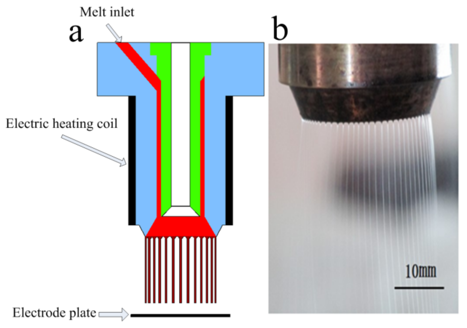
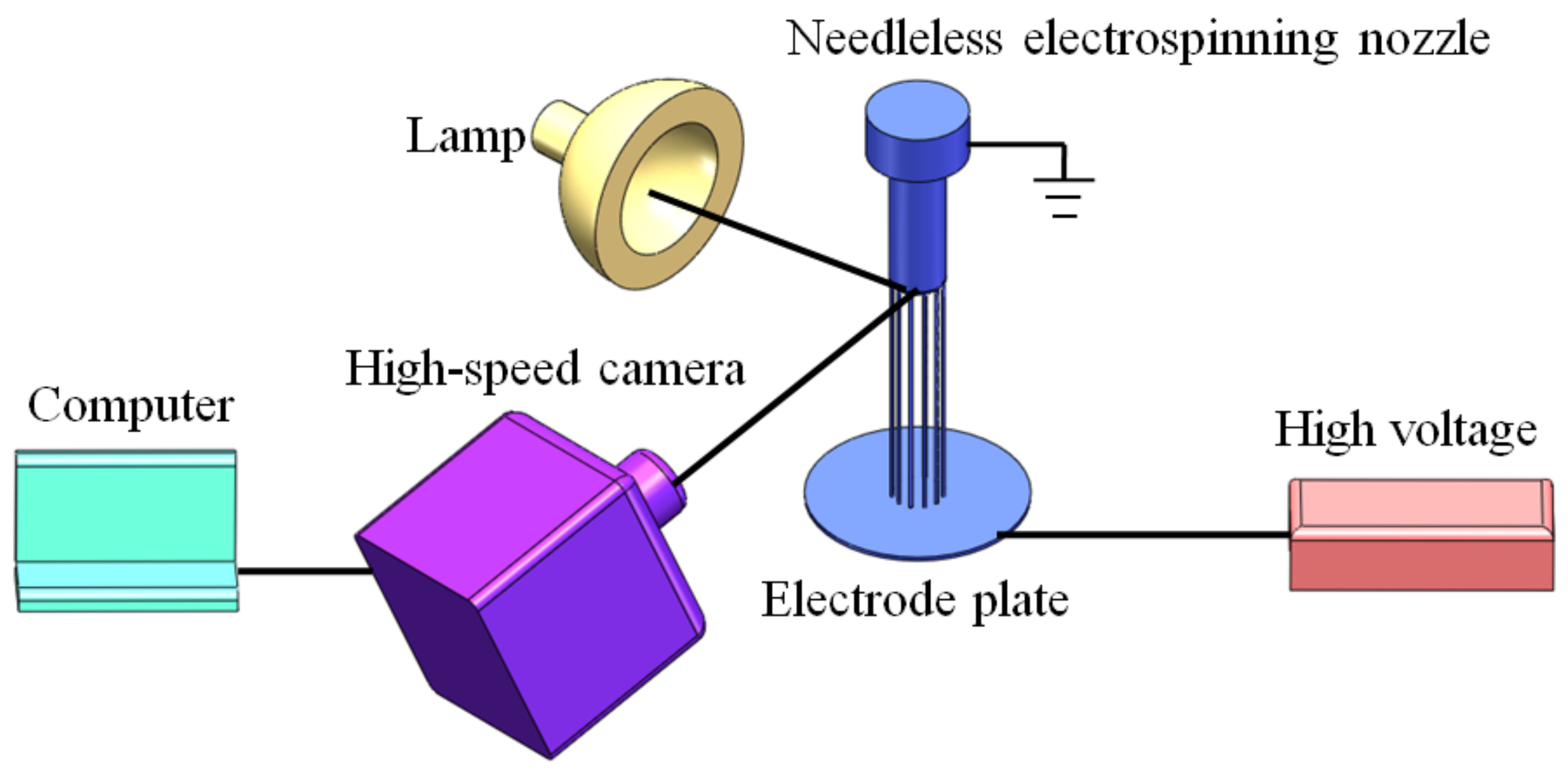
2. Experimental
3. Results and Discussion
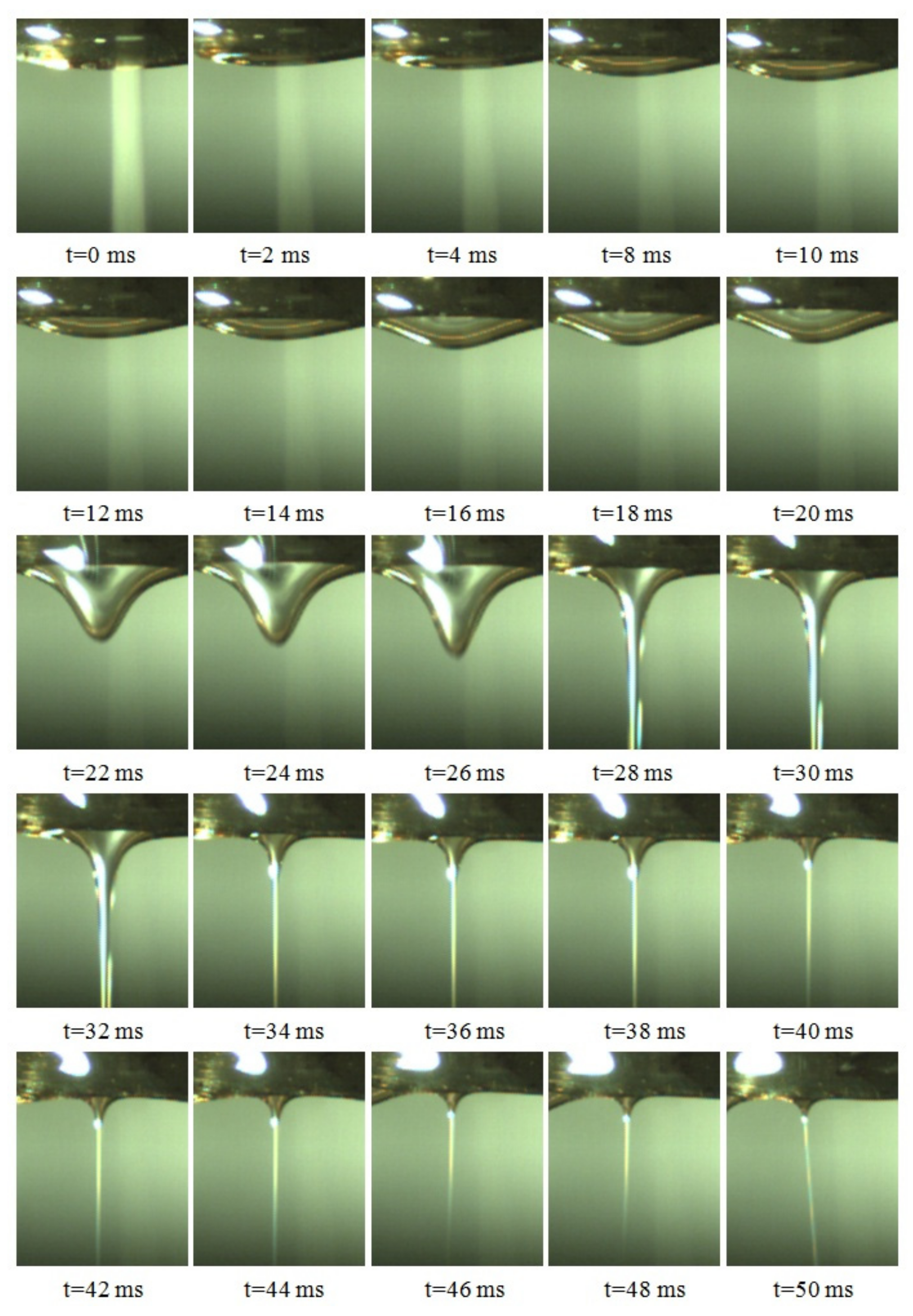
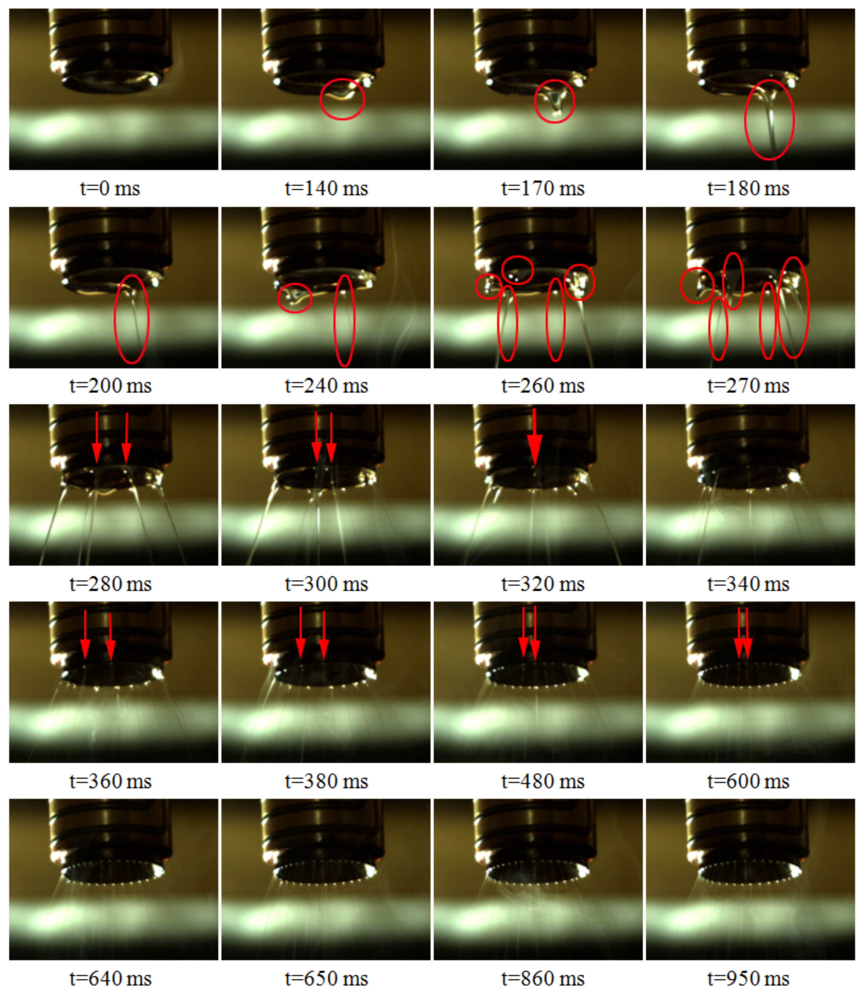
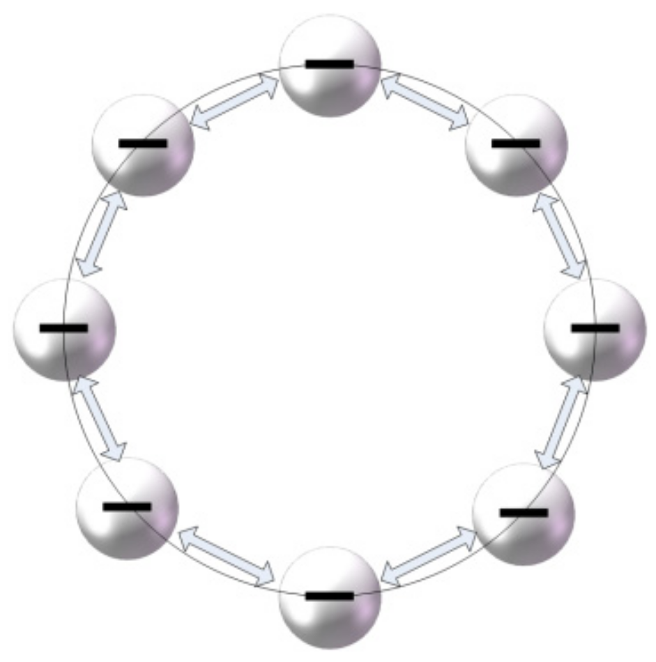
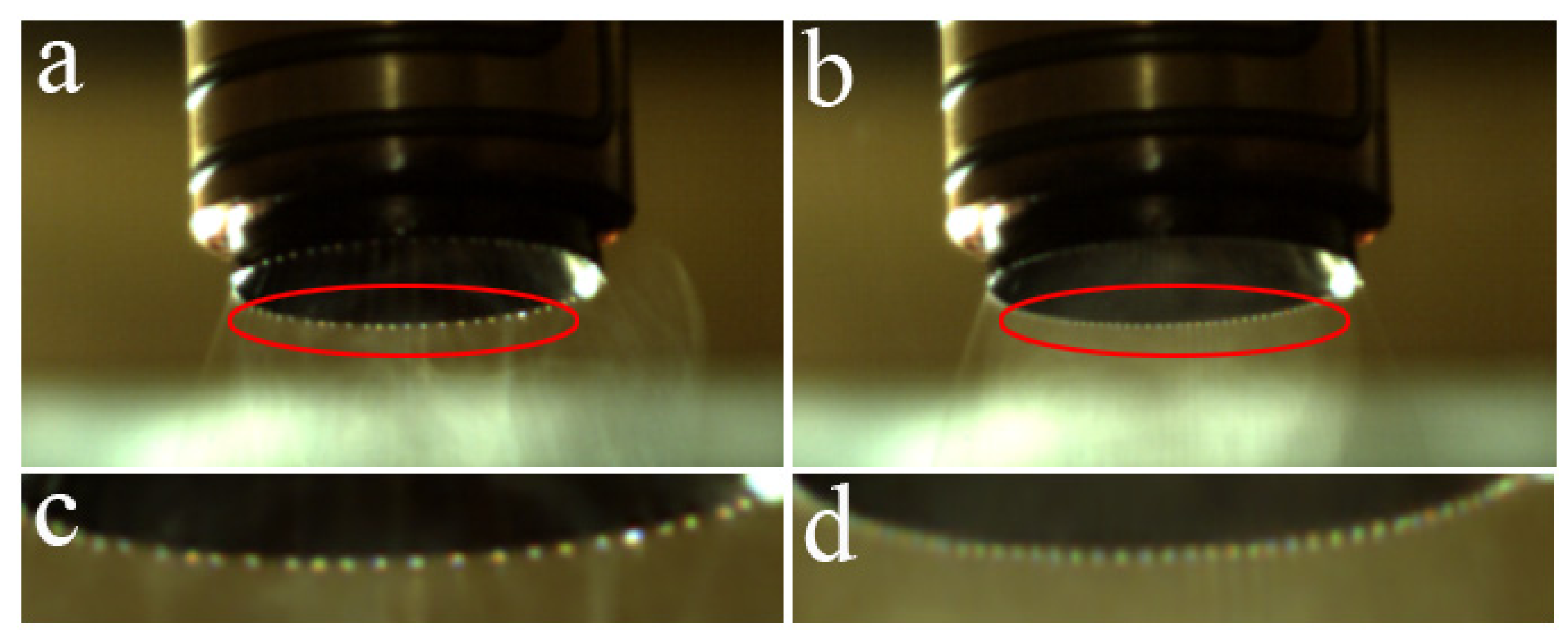
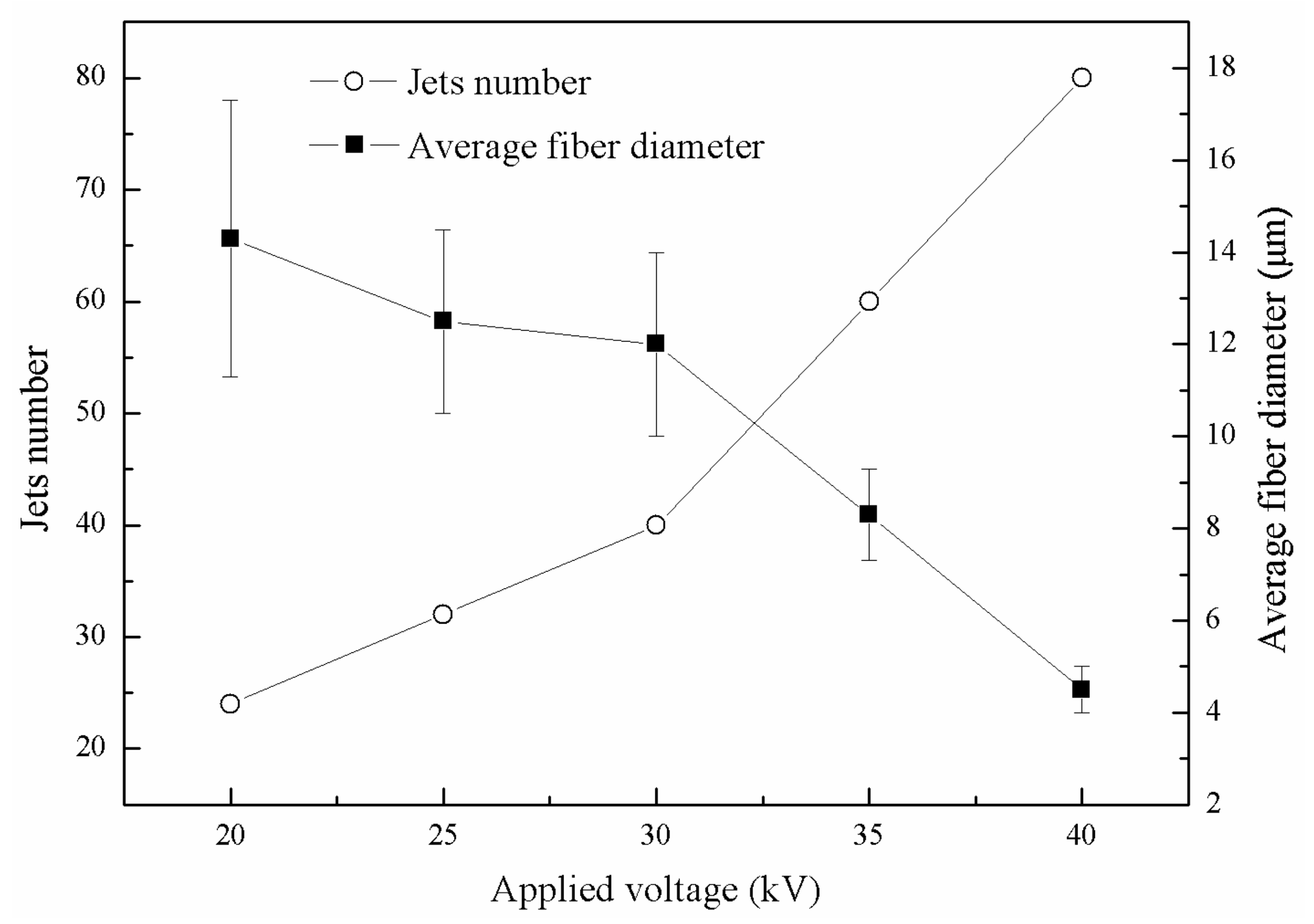
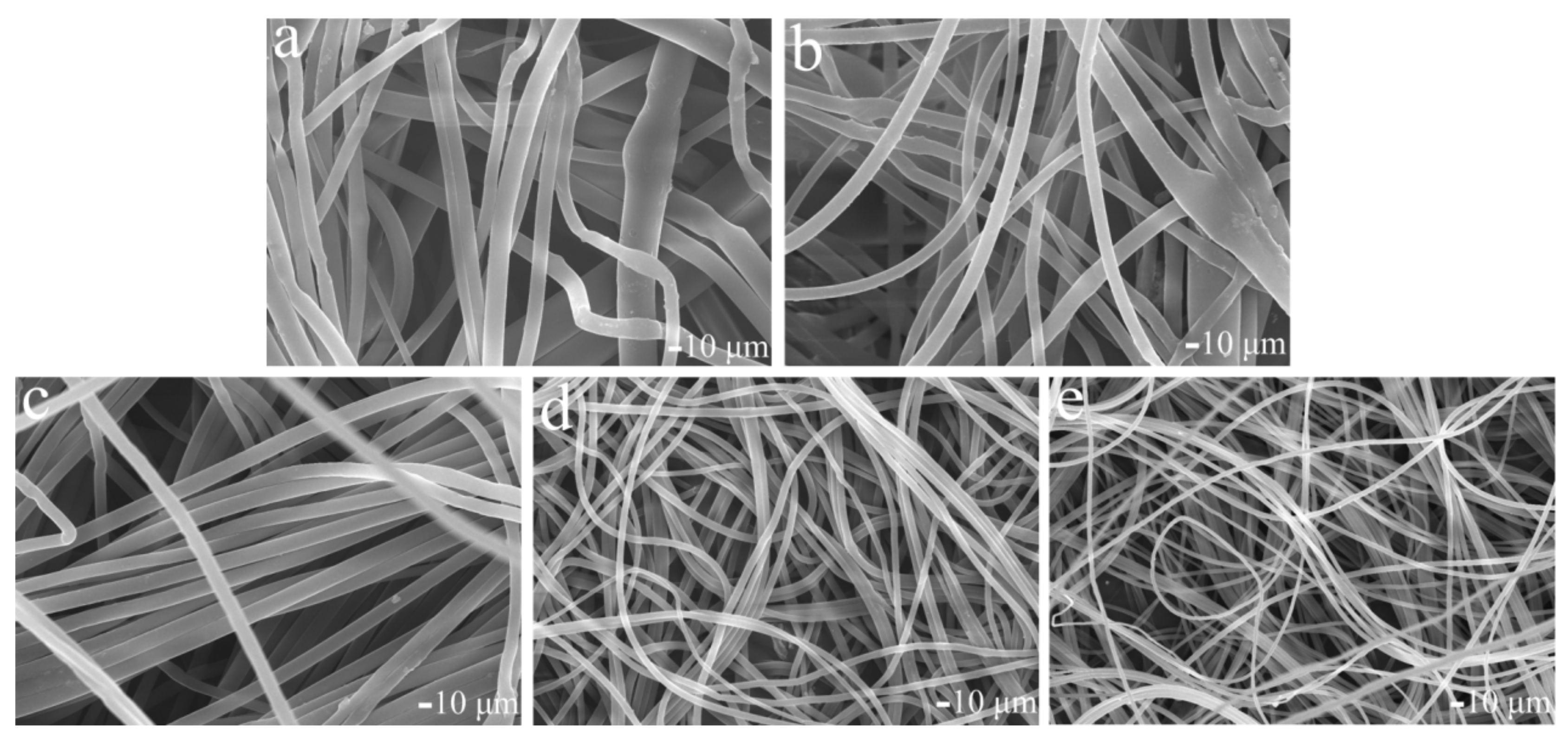
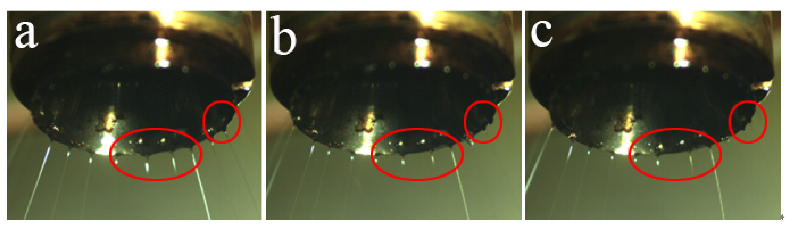
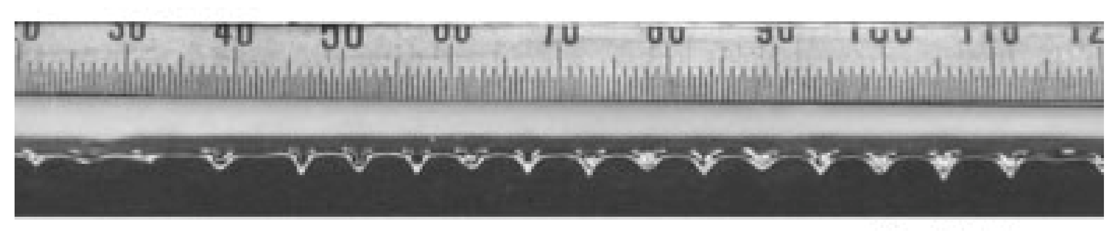
3.1. Theoretical and Experimental Analysis of the Formation of Stable and Uniform Jets
3.2. Theoretical Analysis of the Formation of Jets with Small Spacing
4. Conclusions
Author Contributions
Funding
Conflicts of Interest
References
- Morikawa, K.; Vashisth, A.; Grimme, C.J. Wire melt electrospinning of thin polymeric fibers via strong electrostatic field gradients. Macromol. Mater. Eng. 2019, 304, 1800417. [Google Scholar] [CrossRef]
- Dzenis, Y. Spinning continuous fibers for nanotechnology. Science 2004, 304, 1917–1919. [Google Scholar] [CrossRef] [PubMed]
- Subbiah, T.; Bhat, G.S.; Tock, R.W.; Parameswaran, S.; Ramkumar, S.S. Electrospinning of nanofibers. J. Appl. Polym. Sci. 2005, 96, 557–569. [Google Scholar] [CrossRef]
- Yang, Y.; Li, W.; Yu, D.G.; Wang, G.; Williams, G.R.; Zhang, Z. Tunable drug release from nanofibers coated with blank cellulose acetate layers fabricated using tri-axial electrospinning. Carbohydr. Polym. 2019, 203, 228–237. [Google Scholar] [CrossRef] [PubMed]
- Greiner, A.; Wendorff, J.H. Functional Self-Assembled Nanofibers by Electrospinning. Adv. Polym. Sci. 2008, 219, 107–171. [Google Scholar]
- Wunner, F.M.; Wille, M.L.; Noonan, T.G.; Bas, O.; Dalton, P.D.; De-Juan-Pardo, E.M.; Hutmacher, D.W. Melt electrospinning writing of highly ordered large volume scaffold architectures. Adv. Mater. 2018, 30, 1706570. [Google Scholar] [CrossRef] [PubMed]
- Wróblewska-Krepsztul, J.; Rydzkowski, T.; Michalska-Pożoga, I.; Thakur, V.K. Biopolymers for Biomedical and Pharmaceutical Applications: Recent Advances and Overview of Alginate Electrospinning. Nanomaterials 2019, 9, 404. [Google Scholar] [CrossRef]
- Kriegel, C.; Arrechi, A.; Kit, K.; McClements, D.J.; Weiss, J. Fabrication, functionalization, and application of electrospun biopolymer nanofibers. Crit. Rev. Food Sci. 2008, 48, 775–797. [Google Scholar] [CrossRef]
- Hu, X.; Liu, S.; Zhou, G.; Huang, Y.; Xie, Z.; Jing, X. Electrospinning of polymeric nanofibers for drug delivery applications. J. Control. Release 2014, 185, 12–21. [Google Scholar] [CrossRef]
- Yun, K.M.; Hogan, C.J.; Matsubayashi, Y.; Kawabec, M.; Iskandara, F.; Okuyamaa, K. Nanoparticle filtration by electrospun polymer fibers. Chem. Eng. Sci. 2007, 62, 4751–4759. [Google Scholar] [CrossRef]
- Brown, T.D.; Dalton, P.D.; Hutmacher, D.W. Melt electrospinning today: An opportune time for an emerging polymer process. Prog. Polym. Sci. 2016, 56, 116–166. [Google Scholar] [CrossRef]
- Detta, N.; Brown, T.D.; Edin, F.K.; Albrecht, K.; Chiellini, F.; Chiellini, E.; Dalton, P.D.; Hutmacher, D.W. Melt electrospinning of polycaprolactone and its blends with poly (ethylene glycol). Polym. Int. 2010, 59, 1558–1562. [Google Scholar] [CrossRef]
- Li, H.; Li, Y.; Yang, W.; Cheng, L.; Tan, J. Needleless melt-electrospinning of biodegradable poly (lactic acid) ultrafine fibers for the removal of oil from water. Polymers 2017, 9, 3. [Google Scholar] [CrossRef] [PubMed]
- Zhmayev, E.; Cho, D.; Joo, Y.L. Nanofibers from gas-assisted polymer melt electrospinning. Polymer 2010, 51, 4140–4144. [Google Scholar] [CrossRef]
- Komarek, M.; Martinova, L. Design and Evaluation of Melt-Electrospinning Electrodes. In Proceedings of the 2nd NANOCON International Conference, Olomouc, Czech Republic, 12–14 October 2010. [Google Scholar]
- Shimada, N.; Tsutsumi, H.; Nakane, K.; Ogihara, T.; Ogata, N. Poly (ethylene-co-vinyl alcohol) and Nylon 6/12 nanofibers produced by melt electrospinning system equipped with a line-like laser beam melting device. J. Appl. Polym. Sci. 2010, 116, 2998–3004. [Google Scholar] [CrossRef]
- Fang, J.; Zhang, L.; Sutton, D.; Wang, X.G.; Lin, T. Needleless melt-electrospinning of polypropylene nanofibres. J. Nanomater. 2012, 2012, 1–9. [Google Scholar] [CrossRef]
- Molnar, K.; Nagy, Z.K. Corona-electrospinning: Needleless method for high-throughput continuous nanofiber production. Eur. Polym. J. 2016, 74, 279–286. [Google Scholar] [CrossRef]
- Ali, U.; Niu, H.; Aslam, S.; Jabbar, A.; Rajput, A.W.; Lin, T. Needleless electrospinning using sprocket wheel disk spinneret. J. Mater. Sci. 2017, 52, 7567–7577. [Google Scholar] [CrossRef]
- Lukas, D.; Sarkar, A.; Pokorny, P. Self-organization of jets in electrospinning from free liquid surface: A generalized approach. J. Appl. Phys. 2008, 103, 084309. [Google Scholar] [CrossRef]
- Li, H.; Chen, H.; Zhong, X.; Wu, W.; Ding, Y.; Yang, W. Interjet distance in needleless melt differential electrospinning with umbellate nozzles. J. Appl. Polym. Sci. 2014, 131, 40515. [Google Scholar] [CrossRef]
- Cao, K.; Liu, Y.; Olkhov, A.A.; Siracusa, V.; Iordanskii, A.L. PLLA-PHB fiber membranes obtained by solvent-free electrospinning for short-time drug delivery. Drug Deliv. Transl. Res. 2018, 8, 291–302. [Google Scholar] [CrossRef]
- Zeng, J.; Xu, X.; Chen, X.; Liang, Q.; Bian, X.; Yang, L.; Jing, X. Biodegradable electrospun fibers for drug delivery. J. Control. Release 2003, 92, 227–231. [Google Scholar] [CrossRef]
- Xue, J.; Wu, T.; Dai, Y.; Xia, Y. Electrospinning and electrospun nanofibers: methods, materials, and applications. Chem. Rev. 2019, 119, 5298–5415. [Google Scholar] [CrossRef]
- Lyons, J.; Li, C.; Ko, F. Melt-electrospinning part I: Processing parameters and geometric properties. Polymer 2004, 45, 7597–7603. [Google Scholar] [CrossRef]
- Theron, S.A.; Yarin, A.L.; Zussman, E.; Kroll, E. Multiple jets in electrospinning: Experiment and modeling. Polymer 2005, 46, 2889–2899. [Google Scholar] [CrossRef]


© 2019 by the authors. Licensee MDPI, Basel, Switzerland. This article is an open access article distributed under the terms and conditions of the Creative Commons Attribution (CC BY) license (http://creativecommons.org/licenses/by/4.0/).
Share and Cite
Chen, H.; Wang, C.; Ali, I.; Li, H.; Chen, X.; Yang, W.; Han, W.; Liu, H.; Jiao, D.; Yin, F. Uniform Distribution and Densification of Jets in Needleless Electrospinning Using Annular Tip Nozzle. Polymers 2019, 11, 1301. https://doi.org/10.3390/polym11081301
Chen H, Wang C, Ali I, Li H, Chen X, Yang W, Han W, Liu H, Jiao D, Yin F. Uniform Distribution and Densification of Jets in Needleless Electrospinning Using Annular Tip Nozzle. Polymers. 2019; 11(8):1301. https://doi.org/10.3390/polym11081301
Chicago/Turabian StyleChen, Hongbo, Chuansheng Wang, Imdad Ali, Haoyi Li, Xiaoqing Chen, Weimin Yang, Wenwen Han, Haichao Liu, Dongmei Jiao, and Fengfu Yin. 2019. "Uniform Distribution and Densification of Jets in Needleless Electrospinning Using Annular Tip Nozzle" Polymers 11, no. 8: 1301. https://doi.org/10.3390/polym11081301