Study of a Broadband Difference Interferometer Based on Low-Cost Polymer Slab Waveguides


Department of Optoelectronics, Faculty of Electrical Engineering, Silesian University of Technology, 2 Krzywoustego Str., 44-100 Gliwice, Poland
Nanomaterials 2019, 9(5), 729; https://doi.org/10.3390/nano9050729
Submission received: 20 March 2019
/
Revised: 24 April 2019
/
Accepted: 6 May 2019
/
Published: 11 May 2019
(This article belongs to the Special Issue Nanoscale Optical Sensing)
Abstract
:A model and the waveguide parameters of a broadband, polymer-based slab waveguide difference interferometer is presented in this paper. The parameters were determined based on knowledge of the dispersion in the structure materials used to fabricate the waveguide. The impact of the waveguide layer thickness, propagation path length, and change in the waveguide cover refractive index on the output signal from the system was determined. It has been shown that the direction of the maximum shifting is determined by the thickness of the waveguide layer. A relationship describing the shift in the signal extrema for a change in the waveguide cover refractive index was derived. The results show that the use of a propagation constant simplifies the description of the interferometer. Polymer waveguides, although they have a small contrast in refractive indices, allow for large shifts in the maxima of the signal. The determined shifts in the output signal extrema for polymer waveguides are comparable, and these shifts are larger for some waveguide thicknesses compared to waveguides based on Si3N4.
1. Introduction
Optical, label-free detection methods for applications in the biochemical field have been intensively investigated in recent years [1,2]. Systems of this type have remarkably advantageous properties, such as outstanding sensitivity, detection limit, wide dynamic range, and immunity to interference [3]. There are various methods for detecting effective refractive index changes such as surface plasmon resonance (SPR), microring resonators, reflectometric interference spectroscopy (RifS), and planar waveguide interferometers [4,5]. Mach–Zehnder and Young planar interferometers, which use a single wavelength, are the most sensitive systems in the latter group [1,4]. They can be used to detect changes to the effective refractive index in the order of 10−8.
A division of waveguide interferometers into common and double-path types was proposed in [4,6]. Mach–Zehnder and Young interferometers are typical double-path interferometers. In these interferometers, light propagates along two separate paths (sensor and measurement). Common-path interferometers are systems which have different types of modes (TE, TM), or modes of a different order with different sensitivities to changes in the system parameters, and which propagate along the same path. The impact of a change in the waveguide cover refractive index on the phase velocities of the propagated modes is most often used in these types of structures. The phase difference between modes at the output of the structure and the resulting intensity of light are a function of the waveguide cover refractive index. The mechanism presented is the basis for constructing common-path interferometers [7]. Interference between TE0 and TM0 modes is described in the literature [8,9,10,11,12]. Interference between the modes with different orders was also reported by [13,14]. The impact of changes in the cover refractive index on the mode field distribution in a two-mode structure is described in [15]. Common-path (single-channel) waveguide interferometers are often called difference interferometers.
Broadband interferometers were developed recently. Light from a selected spectral range propagates in these structures. In the case of monochromatic interferometers, phase ambiguity is a problem that is often encountered, which can be eliminated by using a broadband light source [5]. A description of the broadband Mach–Zehnder interferometer can be found in the literature [16,17]. The specific applications of this interferometric system can be found in many publications [18,19,20,21,22,23,24,25,26].
The broadband Young interferometer enables simultaneous measurement of the phase signal for two polarizations over a broad range of wavelengths [27]. The implementation of this interferometric system was discussed in a prior publication [28].
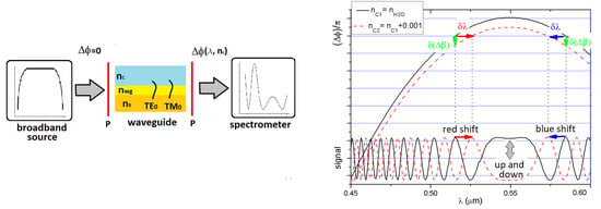
An analysis of the broadband difference interferometer was presented in [29]. In the aforementioned broadband interferometers, Si3N4 was used as a waveguide layer and SiO2 was used as a substrate. These types of structures have high contrast in the refractive index, resulting in a high sensitivity to changes in the system parameters. This paper presents a model describing a broadband difference interferometer based on the SU-8 polymer. In [30], a broadband planar SU-8 polymer-based difference interferometer was analyzed for a waveguide layer with a single selected thickness. In this case, interference maxima shift toward short waves (so-called blue shift). The results in this paper demonstrate the significant impact of the polymer waveguide layer thickness on the output signal from the interferometer. Depending on the thickness of the waveguide layer, it is possible to obtain the shift of the interference maxima towards short or long waves (so-called blue or red shift). The value of the maximum shift is also dependent on the thickness of the waveguide layer. In this paper, it is shown that the increase in the propagation path in the structure results in the increase in the number of maxima in the output signal. The characteristics presented in the paper allow optimization of the waveguide structure for practical applications. This type of research has not been conducted for polymer waveguides with a relatively low contrast in the refractive index in the visible light range.
2. Materials and Interferometer System
Polymer waveguides provide a low-cost alternative to Si3N4-based waveguides. This type of waveguide, is used for transmission between electronic circuits due to the possibility of obtaining relatively low attenuation [31]. Many interferometric structures are designed and implemented using various types of polymers. SU-8 is a common polymer used in this application [32,33].
Initially, this material was developed to meet the needs of the semiconductor industry, which required progressively more sensitive and cheaper photosensitive substances [34]. It was quickly found that the unique properties of SU-8 could also be used to fabricate MEMS and MOEMS. Interest in this polymer in terms of its use in sensor technology has risen considerably [35]. The possibility of thermal modification of the refractive index of the SU-8 layers was shown in [36]. Nowadays, research aims at reducing the hydrophobicity of the polymer surface [37]. There is a possibility of direct laser writing on the SU-8 layer, yielding low-loss waveguide structures [38]. Free-standing waveguides with higher refractive index contrast were also presented [39]. Sensors based on these structures have a high sensitivity to changes in the refractive index.
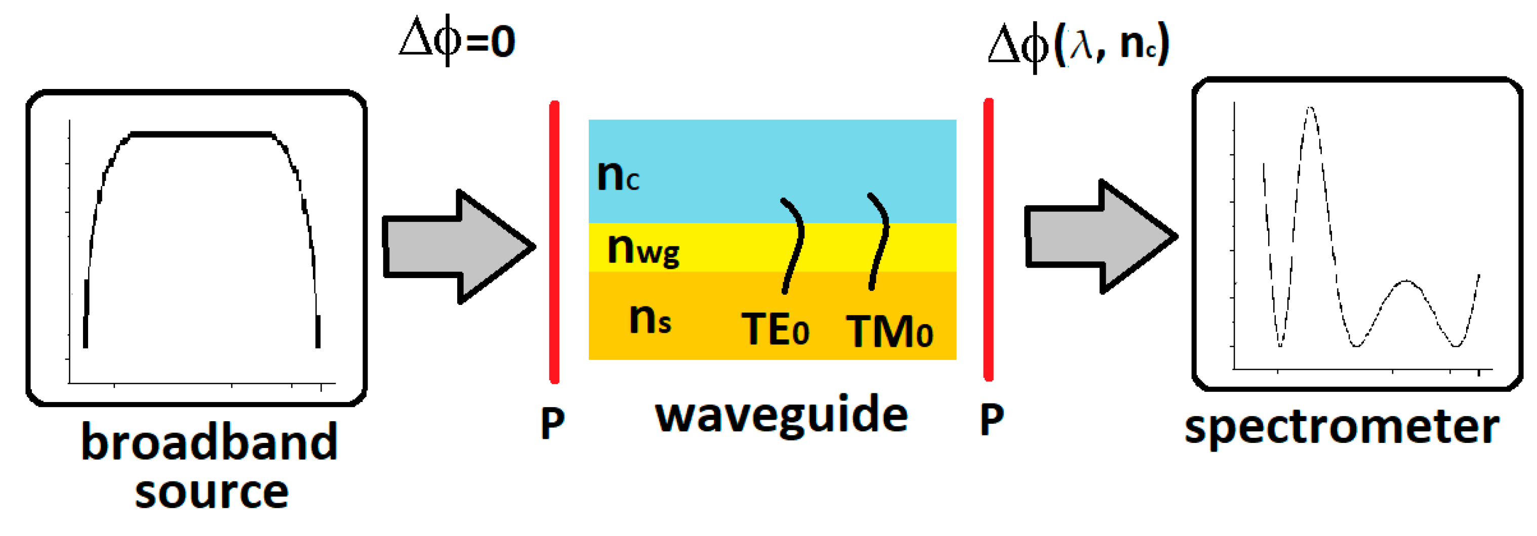
Figure 1 shows a diagram of a broadband difference interferometer.
Light from a broadband source excites the fundamental optical TE0 and TM0 modes in a planar waveguide after passing through a polarizer. A phase difference Δφ accumulates between them during propagation. The spectrometer can be used to record an interference signal in the wavelength domain after passing through the output polarizer [29]. If light with the same optical power distribution I0(λ) is introduced to each of the orthogonal modes TE0 and TM0, the spectral signal I(λ) is given by:
where λ is the electromagnetic wavelength.
The normalized light intensity distribution, at the output In, can be defined as follows:
where Δφ is the phase difference between the modes at the waveguide output [29].
A three-layer system with a SiO2 substrate, the SU-8 polymer waveguide layer, and a water (H2O) cover layer was used to theoretically analyze the polymer broadband difference interferometer. Optical dispersion in the waveguide layer (SU-8) and substrate (SiO2) were taken from ellipsometric measurements presented in the literature [30]. The refractive index dispersion of water was also taken from the literature [40]. The dispersion characteristics are shown in Figure 2. For these calculations, the thickness of the waveguide layer d was assumed as a parameter. The thicknesses of the cover and substrate were assumed to be semi-infinite.
Due to available radiation sources and relatively popular waveguide spectrometers, the analysis was carried out for wavelengths ranging from 450 nm to 600 nm. This choice of spectral range may facilitate simpler experimental verification of the proposed system.
3. Results and Discussions
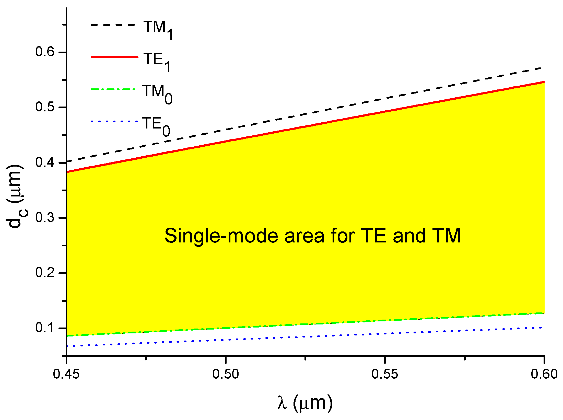
In planar asymmetrical three-layer structures where nc ≠ ns, propagation of the m-order mode is possible only if the waveguide thickness d > dc [41]. These parameters for TE and TM polarization are described by the following equations [41]:
where nc is the refractive index of the cover, ns is the refractive index of the substrate, nwg is the refractive index of the waveguide layers, and m = 0, 1,… is the order of the mode propagating in the waveguide structure [41].
The dependence of the cut-off thickness for various modes (fundamental and the first order modes for both polarizations) on the wavelength is presented in Figure 3. This figure also shows a surface whose points determine the layer thickness and the wavelength for which TEm and TMm are the only allowed modes. The main analysis was performed for a waveguide with thicknesses d3 = 350 nm (Figures 7, 9 and 10) which is a single-mode waveguide in the considered wavelength range. To show the effect of thickness on the characteristics of the interferometer, the characteristics of the waveguides with thickness di = d3 ± 50 nm and dj = d3 ± 100 nm are also presented. Five structures with waveguide thicknesses of d1 = 250 nm, d2 = 300 nm, d3 = 350 nm, d4 = 400 nm, and d5 = 450 nm were selected for further analysis. Structures with a thickness d4 = 400 nm and d5 = 450 nm are not multimode structures over the entire wavelength range, but their characteristics (of the fundamental modes) were included.
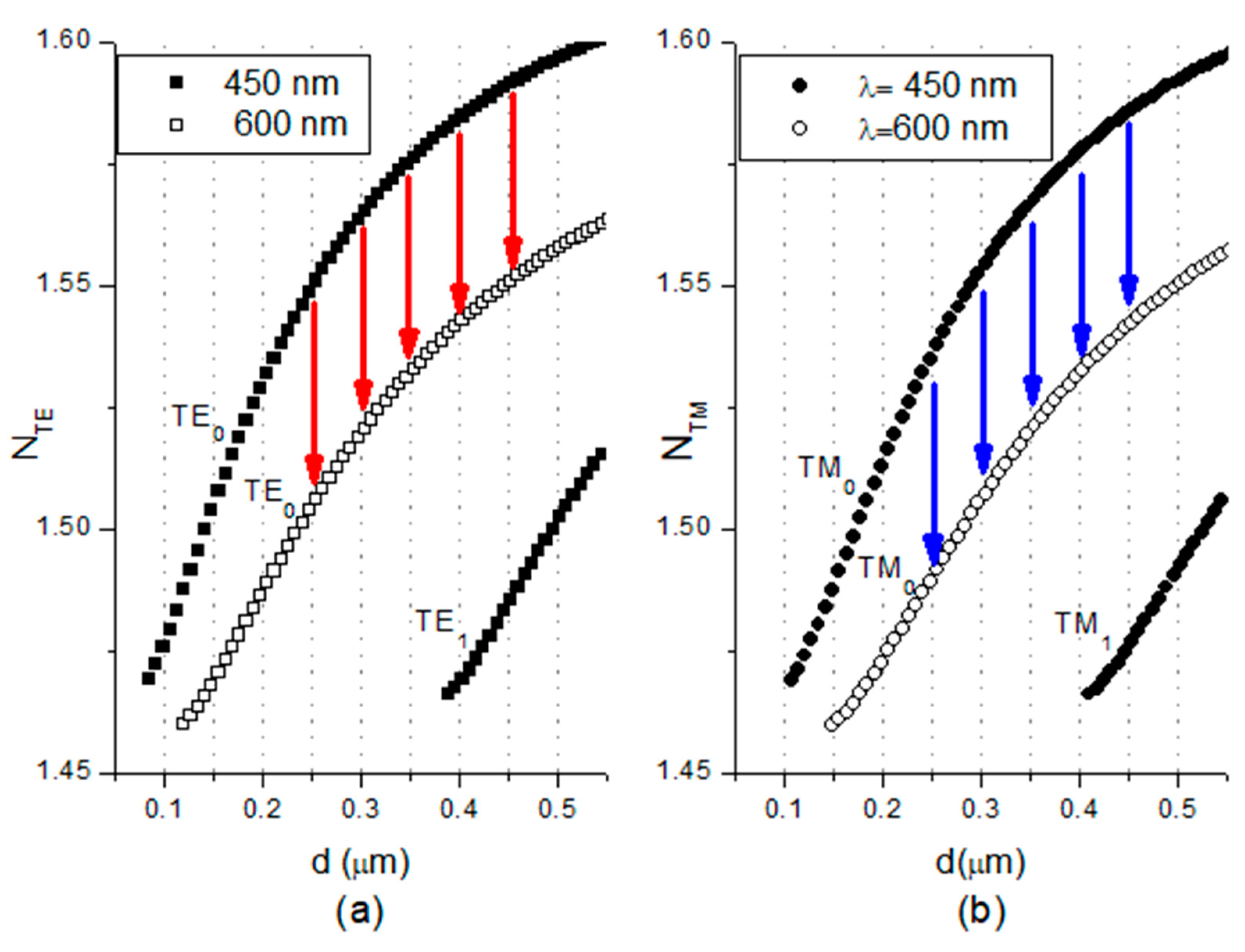
Figure 4 shows the effective refractive indices for the propagating modes at the minimum (450 nm) and maximum (600 nm) wavelengths in the considered interval as a function of the waveguide layer thickness d.
Figure 4 shows changes in the effective refractive index for both polarizations that are marked with arrows. The phase difference Δφ between the modes is a function of propagation path length L, effective refractive indices (NTM and NTE), and wavelength λ. This is described by the following equation [29]:
where nc is the refractive index of the cover.
The mode propagation constant β determines the phase change per unit distance along the propagation path. Therefore, this parameter will be used to describe the broadband interference phenomenon in the next section. Methods for directly measuring and determining differences in the propagation constants Δβ can be found in the literature [42,43]. The relationship between the propagation constant and the effective refractive index is expressed as follows:
after substituting in Equation (3) into Equation (6), one can derive the following:
where Δβ is the difference in the propagation constants for TE and TM modes:
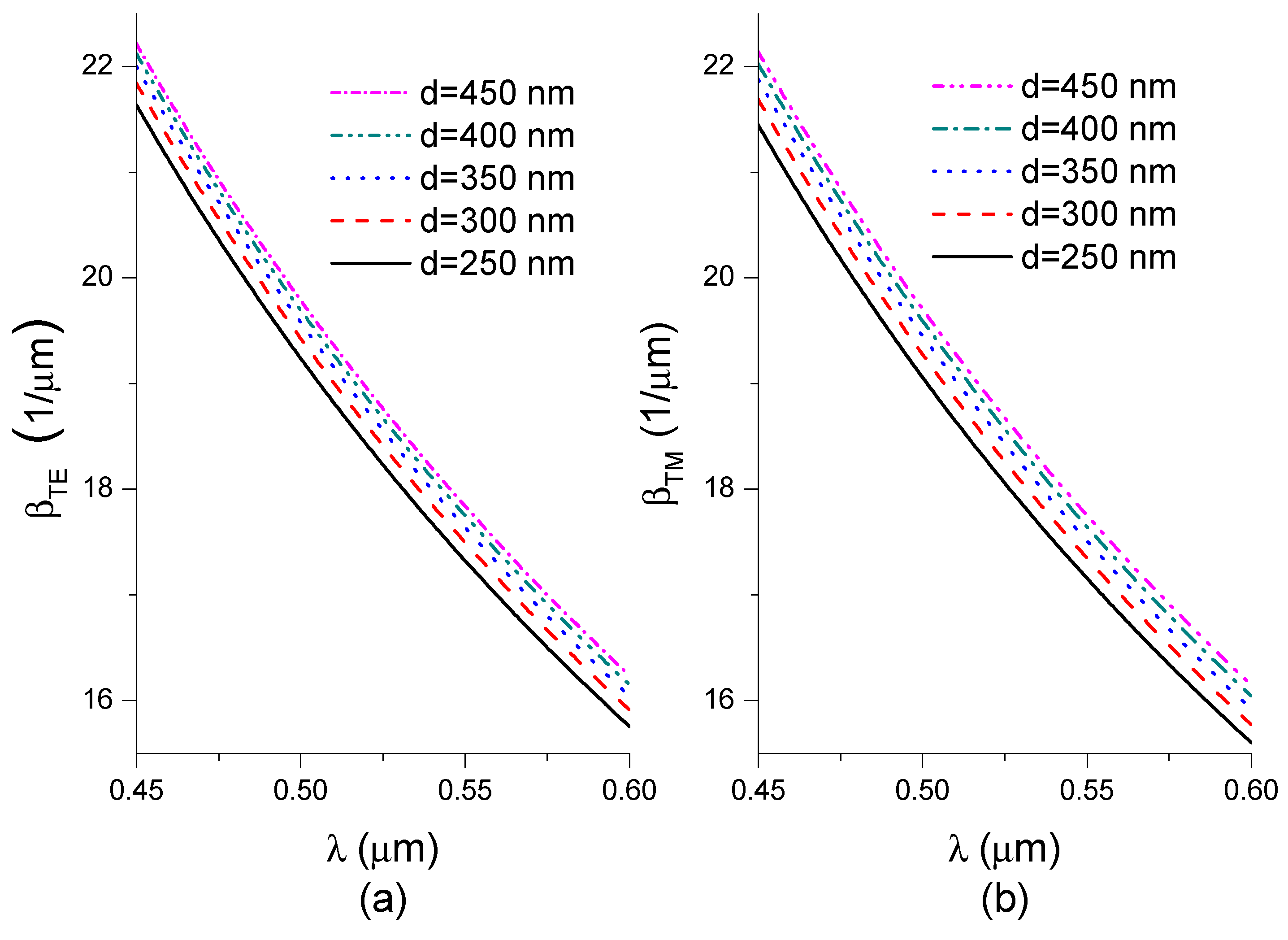
Figure 5 shows the calculated propagation constants for TE0 and TM0 modes at the considered waveguide layer thickness as a function of the wavelength.
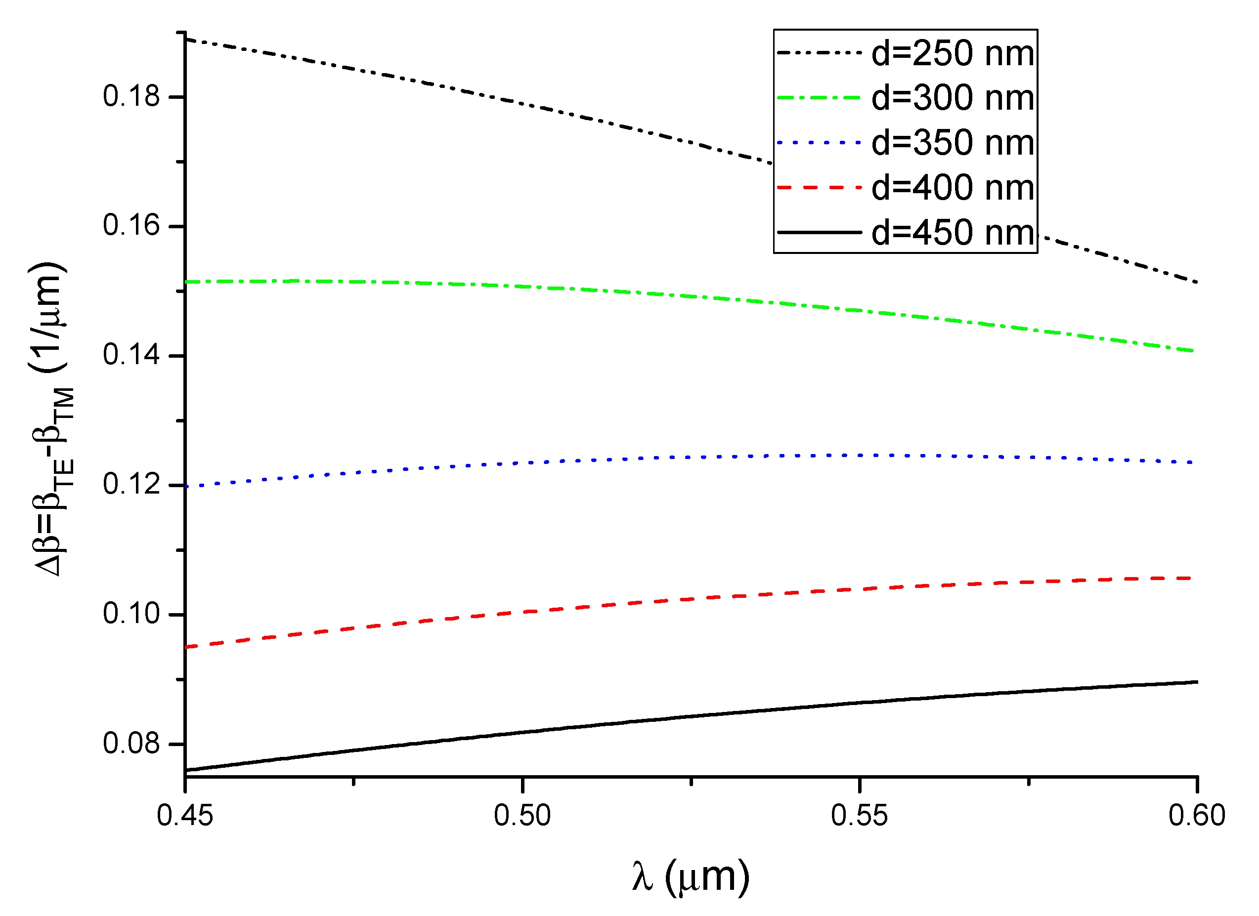
The propagation constants decrease monotonically in the considered wavelength range for both types of propagating modes. β increases as the waveguide thickness increases. It follows from Equation (7) that the shape of the phase difference dependence Δφ(λ, nc), as a function of the wavelength for a given refractive index of the cover nc, is determined by the shape of the function describing Δβ(λ, nc). The shape of the function Δβ(λ, nc) is of key importance for the operation of the interferometric system analyzed here. Figure 6 shows the functions determined for the considered waveguide thickness, where the refractive index of water is denoted nc1.
For the 250 nm thick waveguide, the difference in propagation constants decreases as the wavelength increases. The function Δβ(λ, nc1) increases until it reaches a maximum value and then starts decreasing in the 300 and 350 nm thick waveguides. For other thickness values (400 nm and 450 nm), the difference in propagation constants increases as the wavelength increases.
To illustrate the impact of changes in the cover refractive index on the output signal, the 350 nm thick waveguide was selected because the function Δβ(λ, nc1) is increases and the decreases over the considered wavelength range. Differences in propagation constants for the three-layer system with refractive indices nSiO2/nSU8/nH2O and nSiO2/nSU8/nc2 were determined when the cover refractive index was increased by 0.001 (i.e., nc2(λ) = nH2O(λ) + 0.001). Phase differences between modes were determined using Equation (7). The phase differences for nc1(λ) (continuous line) and nc2(λ) (broken line) after propagating a distance of 12 mm are shown in the upper part of Figure 7. If the value of the waveguide covers refractive index increases, the phase differences decreases for all wavelengths in the range under consideration. The function Δφ(λ, nc2) (broken line) has nearly the same shape as the function Δφ(λ, nc1) and is translated vertically along the y axis.
The lower part of Figure 7 shows the output interference signal for the two waveguide covers analyzed here (solid line: water; broken line: nc2).
Let us consider the wavelength range in which the function Δφ(λ, nc1) (solid line in the upper part of Figure 7) increases. The maximum value of the output signal occurs when Δφ(λ, nc) is equal to an integer multiple of 2π.
If the cover refractive index increases, the value of the function Δφ (λ, nc) will change (broken line in the upper part of Figure 7), and thus the output signal of the system will also change (broken line in the lower part of Figure 5). To visualize these changes, one maximum was chosen in the considered figure. This maximum was connected to the function Δφ(λ, nc1) using a dotted line. For changes in the cover refractive index, the selected maximum shifts towards longer wavelengths.
If we consider the wavelength range in which the function Δφ(λ, nc) decreases, then the extrema of the output signal will shift towards shorter wavelengths as the refractive index increases.
If the function Δφ(λ, nc1) is constant over a certain wavelength range (around maximum), then the function Δφ(λ, nc2) will also be constant in this interval (albeit with a different value compared to the case with nc) when the refractive index changes. The interference signal in this interval will change by the same value for each wavelength in this range.
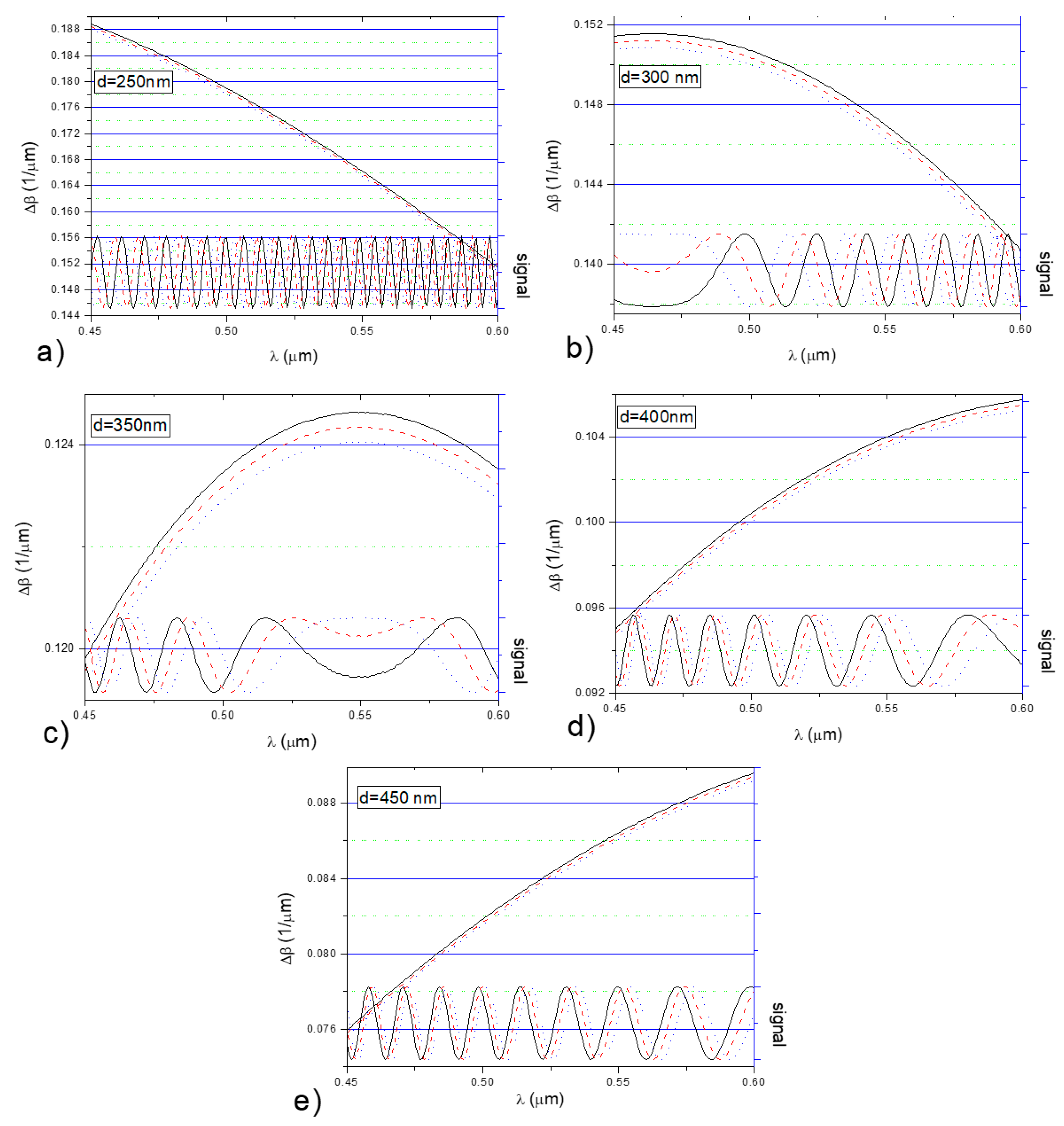
Figure 8 shows the impact of changes in the cover refractive index on Δβ(λ, nc) and the output signal for the previously selected waveguide thickness values (250 nm, 300 nm, 350 nm, 400 nm, and 450 nm). The differences in the propagation constants for the three-layer system were determined with given levels of dispersion in the cover (water), i.e., when nc1(λ) = nH2O(λ), nc2(λ) = nH2O(λ) + 0.001 (broken line), and nc3(λ) = nH2O(λ) + 0.002 (dotted line).
The distance between extrema of the output signal (oscillation period) in the wavelength domain depends on the slope (derivative) of Δβ. If the slope of Δβ decreases, the oscillation period increases. The shift of the signal extrema due to an increase in the cover refractive index is determined by the monotonicity of Δβ.
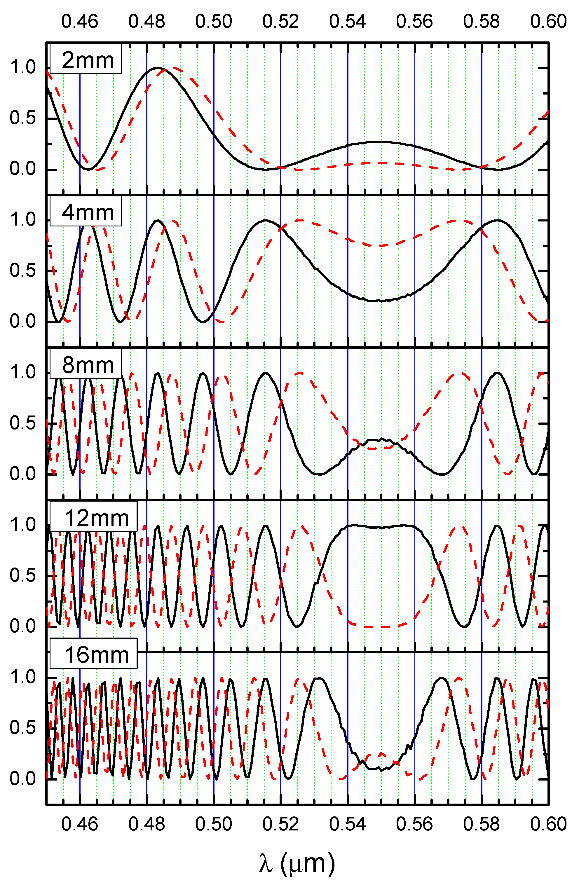
According to Equation (1) and (7), the oscillating output signal depends on the length of propagation path L in the structure. Figure 9 shows the calculated signal as a function of the wavelength when d = 350 nm for the propagation path lengths of L1 = 2 mm, L2 = 4 mm, L3 = 8 mm, L4 = 12 mm, and L5 = 16 mm.
The phase difference increases as the propagation path increases linearly for each wavelength according to Equation (5), which increases the number of recorded extrema. It is worth noting that, just like the case of a broadband Mach–Zhender interferometer [5], the shift in the extrema does not depend on the length of the propagation path.
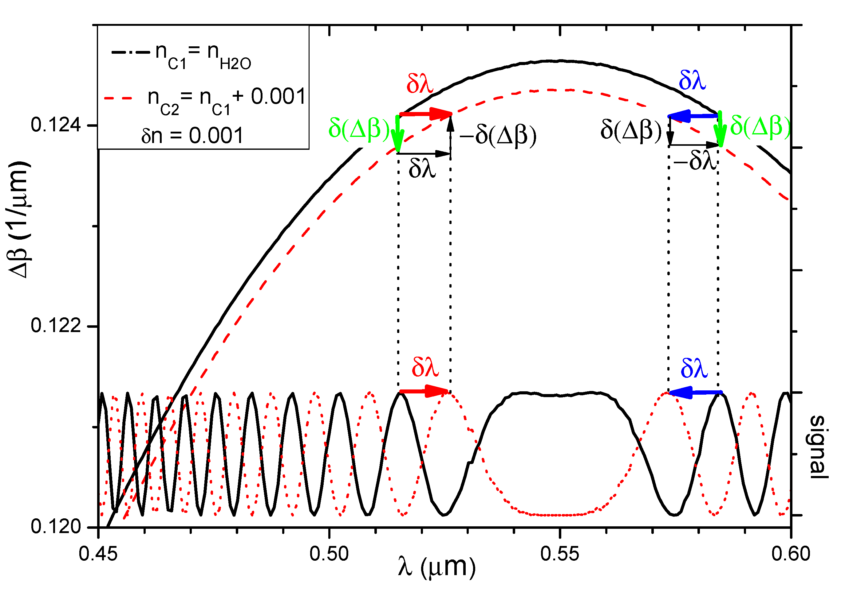
Figure 10 shows the functions Δβ(λ, nc) and interference signal. Assuming the equality of partial derivatives of the Δβ(λ, nc) function with respect to the wavelength for the cover refractive index nc1 and nc2 = nc1 + δn (δn, non-significant change in the refractive index) for the same λ values, one can write:
As shown in Figure 10, the quotient of the change δ(Δβ) of the difference of propagation constants divided by the change of the location of extremum δλ can be associated with the partial derivative of the function Δβ(λ, nc) with respect to the wavelength by the relationship:
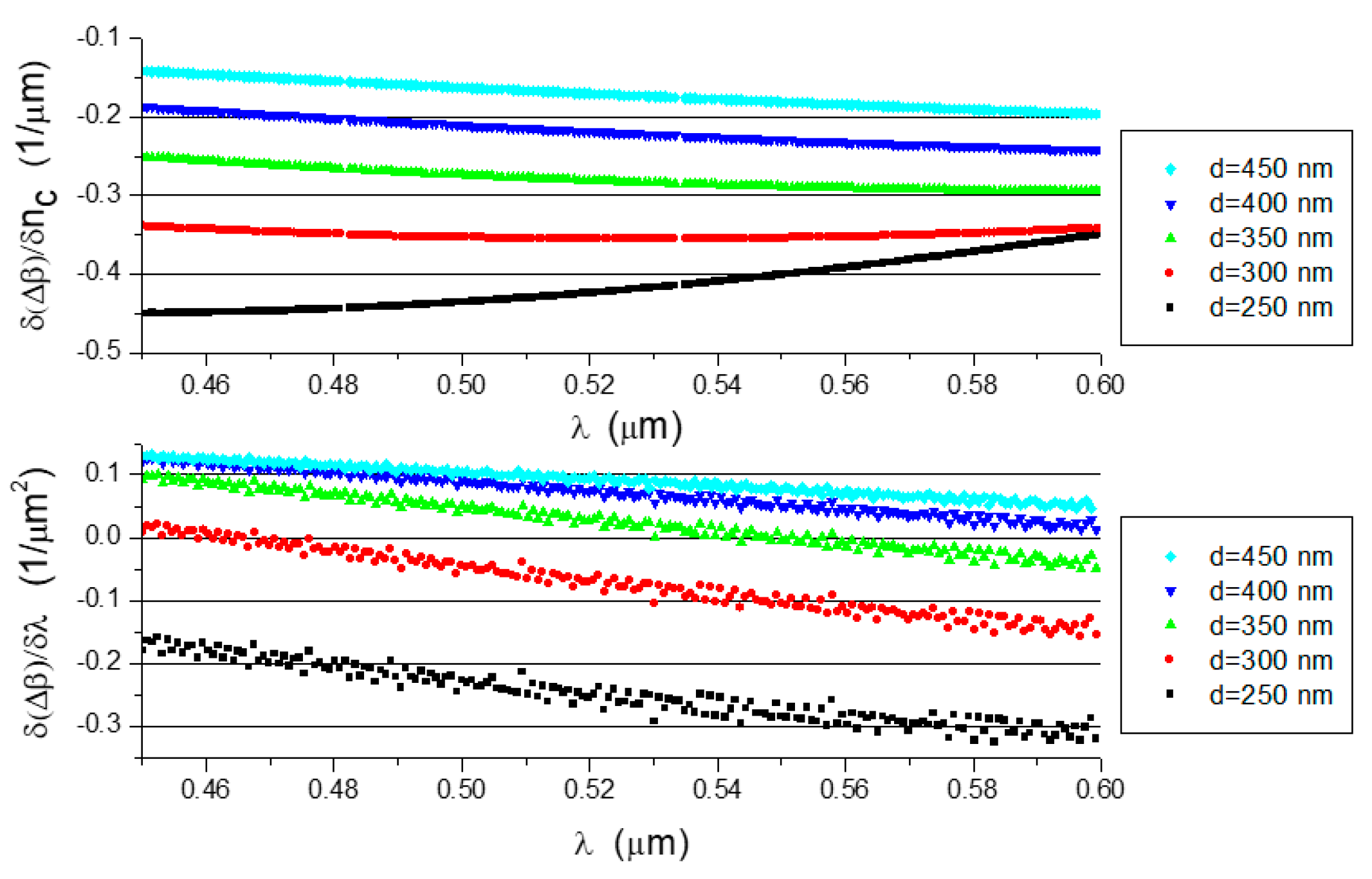
δ(Δβ) can be expressed by the partial derivative of the function Δβ(λ, nc) with respect to the cover refractive index and the change of the cover refractive index δnc:
taking into account (9), after substituting in (10) the expression (11) and transforming, one obtains:
the numerically-determined derivatives and for the analyzed waveguide structures are shown in Figure 11. The derivatives are slowly changing functions with negative values in the analyzed domain.
The derivatives are approximately linear and they have small values for some waveguide thicknesses, including a zero value.
The shifts in the extrema δλ for structures with the considered waveguide thickness were determined using Equation (12), and the results are shown in Figure 12. The change in the refractive index was set to δnc = 0.01 [29] in order to compare the SiO2/Si3N4/H2O structures.
The negative shift in the extrema (blue shift) is obtained over the entire wavelength range of the 250 nm thick waveguides. Both types of shifts (red and blue shift) are observed (some points are not visible due to their high values) in structures with thickness values of 300 and 350 nm. The shift of extrema δλ diverges to infinity as the value of the function tends to zero. A positive shift in the output signal extrema (red shift) is obtained over the whole range for waveguides with thickness values of 400 and 450 nm.
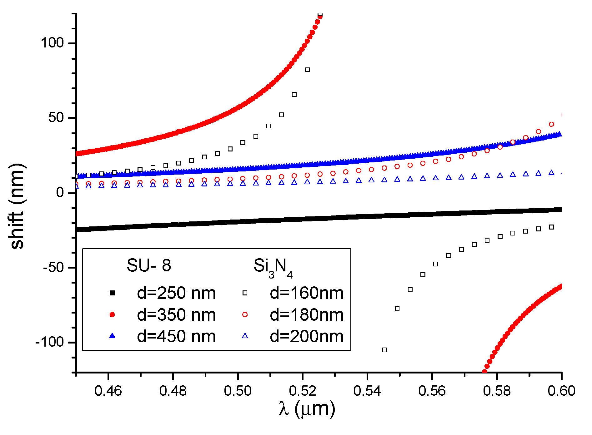
Figure 13 shows the shifts in the maxima for the SU-8 and Si3N4 waveguides as the cover refractive index was increased by 0.01 (data for Si3N4 waveguides was taken from the literature [29]). Three thickness values of the structure were selected for each material. As can be seen in the figure, a higher maximum shift can be obtained for polymer waveguides as compared with Si3N4 based waveguides. According to Equation (11), a small value of in the denominator of Equation (11) causes a relatively large shift of the spectrum maxima at the output, despite the smaller value of in polymer waveguides.
The experimental implementation of a broadband differential interferometer for a waveguide with low contrast of refractive indexes has been presented in [44]. The visible spectrum light (450–750 nm) was introduced into the waveguide from the xenon lamp. The interference signal was obtained after passing the L = 20 mm propagation path through the TE0 and TM0 modes. It has been shown that the change in the refractive index of the cover causes the registered maxima of the interference signal to be shifted only for one waveguide. However, the impact of geometric parameters of waveguides on the recorded interference signal has not been considered in this work.
4. Conclusions
Polymer planar waveguides, due to the relatively low cost of manufacture, but also the possibility of obtaining a relatively low attenuation of the optical modes are used in the technology of sensors. The polymer SU-8 is a material that is frequently used in the technology of MEMS and also for the construction of waveguide interferometer systems. The model for a broadband difference interferometer based on the polymer SU-8 shows that the waveguide layer thickness has a significant influence on the output signal from the system. For the selected thickness (e.g., 250 nm, 400 nm, and 450 nm), the sinusoidal output signal shifts monotonically as the cover refractive index changes. An algorithm for determining a change in the phase difference [16] can be used with systems that include this type of waveguide. For other waveguide thicknesses (e.g., 300 nm and 350 nm), there is the possibility of detection described in [17] when a change in the cover refractive index causes the same change in the phase difference at the system output within a selected wavelength range. The shift in the extrema in the output signal is directly proportional to and inversely proportional to . A relatively large shift of extrema is obtained in waveguides with thicknesses at which the derivative in the denominator reaches low values. The determined shifts in the output signal extrema for polymer waveguides are comparable, and these shifts are larger for some waveguide thicknesses compared to waveguides based on Si3N4.
Funding
This work was supported by the Rector of the Silesian University of Technology within grant agreement No. 05/040/RGH15/0009.
Conflicts of Interest
The author declares no conflict of interest.
References
- Makarona, E.; Petrou, P.; Kakabakos, S.; Misiakos, K.; Raptis, I. Point-of-need based on planar optical interferometry. Botechnol. Adv. 2016, 34, 209–233. [Google Scholar] [CrossRef]
- Estevez, M.C.; Alvarez, M.; Lechuga, L.M. Integrated optical devces for lab-on-a-chip biosensing applications. Laser Photonics Rev. 2012, 6, 463–487. [Google Scholar] [CrossRef]
- McDonagh, C.; Burke, C.S.; Maccraith, B.D. Optical chemical sensors. Chem. Rev. 2008, 108, 400–422. [Google Scholar] [CrossRef] [PubMed]
- Kozma, P.; Kehl, F.; Ehrentreich-Forster, E.; Stamm, C.; Bier, F.F. Integrated planar optical waveguide interferometer biosensors: A comparative review. Biosens. Bioelectron. 2014, 58, 287–307. [Google Scholar] [CrossRef]
- Kitsara, M.; Misiakos, K.; Raptis, I.; Makarona, E. Integrated optical frequency-resolved Mach-Zehnder interferometers for label-free affinity sensing. Opt. Express 2010, 18, 8193–8206. [Google Scholar] [CrossRef]
- Campbell, D. Interferometric Biosensors. In Principles of Bacterial Detection; Zourob, M., Elwary, S., Turner, A., Eds.; Springer: Montreal, QC, Canada, 2008; pp. 169–211. ISBN 978-0-387-75112-2. [Google Scholar]
- Lukosz, W. Integrated optical chemical and direct biochemical sensors. Sens. Actuators B-Chem. 1995, 29, 37–50. [Google Scholar] [CrossRef]
- Stamm, C.; Lukosz, W. Integrated optical difference interferometer as immunosensor. Sens. Actuators B-Chem. B 1996, 31, 203–207. [Google Scholar] [CrossRef]
- Lukosz, W.; Stamm, C.; Moser, H.R.; Ryf, R.; Dübendorfer, J. Difference interferometer with new phase-measurement method as integrated-optical refractometer, humidity sensor and biosensor. Sens. Actuators B-Chem. 1997, 39, 316–323. [Google Scholar] [CrossRef]
- Stamm, C.; Dangel, R.; Lukosz, W. Biosensing with the integrated-optical difference interferometer: Dual-wavelength operation. Opt. Commun. 1998, 153, 347–359. [Google Scholar] [CrossRef]
- Qi, Z.; Itoh, K.; Murabayashi, M.; Yangi, H.A. Composite Optical Waveguide-Based Polarimetric Interferometer for Chemical and Biological Sensing Applications. J. Lightw. Technol. 2000, 18, 1106–1110. [Google Scholar] [CrossRef]
- Tyszkiewicz, C.; Pustelny, T. Differential interferometry in planar waveguide structures with ferronematic layer. Opt. Appl. 2004, 34, 507–514. [Google Scholar]
- Zinoviev, K.E.; González-Guerrero, A.B.; Domínguez, C.; Lechuga, L.M. Integrated Bimodal Waveguide Interferometric Biosensor for Label-Free Analysis. J. Lightw. Technol. 2011, 29, 1926–1930. [Google Scholar] [CrossRef] [Green Version]
- Gut, K. A suggestion of utilizing bimodal layers of the polymer SU8 for the purpose of monitoring the changes in the refractive index. Opt. Appl. 2012, 42, 407–416. [Google Scholar] [CrossRef]
- Gut, K.; Karasiński, P.; Wójcik, W.; Rogoziński, R.; Opilski, Z.; Opilski, A. Applicability of interference TE0-TM0 modes and TE0-TE1 modes to the construction of waveguide sensors. Opt. Appl. 1999, 29, 101–110. [Google Scholar]
- Misiakos, K.; Raptis, I.; Salapatas, A.; Makarona, E.; Bostials, A.; Hoekman, M.; Stoffer, R.; Jobst, G. Broad-band Mach-Zehnder interferometers as high performance refractive index sensors: Theory and monolithic implementation. Opt. Express 2014, 22, 8856–8870. [Google Scholar] [CrossRef]
- Misiakos, K.; Raptis, I.; Makarona, E.; Botsialas, A.; Salapatas, A.; Oikonomou, P.; Psarouli, A.; Petrou, P.S.; Kakabakos, S.E.; Tukkiniemi, K.; et al. All-silicon monolithic Mach-Zehnder interferometer as a refractive index and bio-chemical sensor. Opt. Express 2014, 22, 26803–26813. [Google Scholar] [CrossRef]
- Gajos, K.; Angelopoulou, M.; Petrou, P.; Awsiuk, K.; Kakabakos, S.; Haasnoot, W.; Bernasik, A.; Rysz, J.; Marzec, M.M.; Misiakos, K.; et al. Imaging and chemical surface analysis of biomolecular functionalization of monolithically integrated on silicon Mach-Zehnder interferometric immunosensors. Appl. Surf. Sci. 2016, 385, 529–542. [Google Scholar] [CrossRef]
- Gajos, K.; Budkowski, A.; Petrou, P.; Pagkali, V.; Awsiuk, K.; Bernasik, A.; Misiakos, K.; Raptis, I.; Kakabakos, S. Protein adsorption/desorption and antibody binding stoichiometry on silicon interferometric biosensors examined with TOF-SIMS. Appl. Surf. Sci. 2018, 444, 187–196. [Google Scholar] [CrossRef]
- Anastasopoulou, M.; Malainou, A.; Salapatas, A.; Chronis, N.; Raptis, I.; Misiakos, K. Label-free detection of the IL-6 and IL-8 interleukines through monolithic silicon photonic chips and simultaneous dual polarization optics. Sens. Actuators B-Chem. 2018, 256, 304–309. [Google Scholar] [CrossRef]
- Gajos, K.; Budkowski, A.; Tsialla, Z.; Petrou, P.; Awsiuk, K.; Dąbczyński, P.; Bernasik, A.; Rysz, J.; Misiakos, K.; Raptis, I.; et al. Contact pin-printing of albumin-fungicide conjugate for silicon nitride-based sensors biofunctionalization: Multi-technique surface analysis for optimum immunoassay performance. Appl. Surf. Sci. 2017, 401, 79–86. [Google Scholar] [CrossRef]
- Psarouli, A.; Botsialas, A.; Salapatas, A.; Stefanitsis, G.; Nikita, D.; Jobst, G.; Chaniotakis, N.; Goustouridis, D.; Makarona, E.; Petrou, P.S.; et al. Fast label-free detection of C-reactive protein using broad-band Mach-Zehnder interferometers integrated on silicon chip. Talanta 2017, 165, 458–465. [Google Scholar] [CrossRef]
- Pagkali, V.; Petrou, P.S.; Salapatas, A.; Makarona, E.; Peters, J.; Haasnoot, W.; Jobst, G.; Economou, A.; Misiakos, K.; Raptis, I.; et al. Detection of ochratoxin A in beer samples with a label-free monolithically integrated optoelectronic biosensor. J. Hazard. Mater. 2017, 323, 75–83. [Google Scholar] [CrossRef]
- Gajos, K.; Budkowski, A.; Pagkali, V.; Petrou, P.S.; Biernat, M.; Awsiuk, K.; Rysz, J.; Bernasik, A.; Misiakos, K.; Raptis, I.; et al. Indirect immunoassay on functionalized silicon surface: Molecular arrangement, composition and orientation examined step-by-step with multi-technique and multivariate analysis. Colloids Surf. B 2017, 150, 437–444. [Google Scholar] [CrossRef]
- Psarouli, A.; Salapatas, A.; Botsialas, A.; Petrou, P.S.; Raptis, I.; Makarona, E.; Jobst, G.; Tukkiniemi, K.; Sopanen, M.; Stoffer, R.; et al. Monolithically integrated broad-band Mach-Zehnder interferometers for highly sensitive label-free detection of biomolecules through dual polarization optics. Sci. Rep. 2015, 5, 17600. [Google Scholar] [CrossRef] [Green Version]
- Angelopoulou, Μ.; Botsialas, A.; Salapatas, A.; Petrou, P.S.; Haasnoot, W.; Makarona, E.; Jobst, G.; Goustouridis, D.; Siafaka-Kapadai, A.; Raptis, I.; et al. Assessment of goat milk adulteration with a label-free monolithically integrated optoelectronic biosensor. Anal. Bioanal. Chem. 2015, 407, 3995–4004. [Google Scholar] [CrossRef]
- Makarona, E.; Salapatas, A.; Raptis, I.; Petrou, P.; Kakabakos, S.; Stavra, E.; Malainou, A.; Misiakos, K. Broadband Young interferometry for simultaneous dual polarization bioanalytics. J. Opt. Soc. Am. B 2017, 34, 1691–1698. [Google Scholar] [CrossRef]
- Stavra, E.; Malainou, A.; Salapatas, A.; Botsialas, A.; Petrou, P.; Raptis, I.; Makarona, E.; Kakabakos, S.E.; Misiakos, K. Monolithically-integrated Young interferometers for label-free and multiplexed detection of biomolecules. In Proceedings of the Silicon Photonics XI (SPIE), San Francisco, CA, USA, 13–18 February 2016; Reed, G.T., Kinghts, A.P., Eds.; International Society for Optics and Photonics: Orlando, FL, USA, 2016; Volume 9752, p. 97520N. [Google Scholar] [CrossRef]
- Gut, K. Broad-band difference interferometer as a refractive index sensor. Opt. Express 2017, 25, 31111–31121. [Google Scholar] [CrossRef]
- Gut, K.; Opilski, Z. Spectropolarimetric analyses of optical single mode SU8 waveguide layers. Bull. Pol. Acad. Sci. Tech. 2015, 63, 349–352. [Google Scholar] [CrossRef] [Green Version]
- Dangel, R.; Hofrichter, J.; Horst, F.; Jubin, D.; La Porta, A.; Meier, N.; Soganci, I.M.; Weiss, J.; Offrein, B.J. Polymer waveguides for electro-optical integration in data centers and high-performance computers. Opt. Express 2015, 23, 4736–4750. [Google Scholar] [CrossRef]
- Azuelos, P.; Girault, P.; Lorrain, N.; Poffo, L.; Guendouz, M.; Thual, M.; Lemaître, J.; Pirasteh, P.; Hardy, I.; Charrier, J. High sensitivity optical biosensor based on polymer materials and using the Vernier effect. Opt. Express 2017, 25, 30799–30806. [Google Scholar] [CrossRef]
- Shew, B.Y.; Cheng, Y.C.; Tsai, Y.H. Monolithic SU-8 micro-interferometer for biochemical detection. Sens. Actuators A-Phys. 2008, 141, 299–306. [Google Scholar] [CrossRef]
- Bêche, B.; Pelletier, N.; Gaviot, E. Single-mode TE00–TM00 optical waveguides on SU-8 polymer. Opt. Commun. 2004, 230, 91–94. [Google Scholar] [CrossRef]
- Sameoto, D.; Tsang, S.H.; Parameswaran, M. Polymer MEMS processing for multi-user applications. Sens. Actuators A-Phys. 2007, 134, 457–464. [Google Scholar] [CrossRef]
- Wang, X.B.; Sun, J.; Chen, C.M.; Sun, X.Q.; Wang, F.; Zhang, D.M. Thermal UV treatment on SU-8 polymer for integrated optics. Opt. Mater. Express 2014, 4, 509–517. [Google Scholar] [CrossRef]
- Ramirez, J.C.; Schianti, J.N.; Souto, D.E.P.; Kubota, L.T.; Hernandez-Figueroa, H.E.; Gabrielli, L.H. Dielectric barrier discharge plasma treatment of modified SU-8 for biosensing applications. Biomed. Opt. Express 2018, 9, 2168–2175. [Google Scholar] [CrossRef] [Green Version]
- Ramirez, J.C.; Schianti, J.N.; Almeida, M.G.; Pavani, A.; Panepucci, R.R.; Hernandez-Figueroa, H.E.; Gabrielli, L.H. Low-loss modified SU-8 waveguides by direct laser writing at 405 nm. Opt. Mater. Express 2017, 7, 2651–2659. [Google Scholar] [CrossRef]
- Marinins, A.; Knudde, N.; Popov, S. Air-Suspended SU-8 Strip Waveguides with High Refractive Index Contrast. IEEE Photonics Technol. Lett. 2016, 28, 1862–1865. [Google Scholar] [CrossRef]
- Daimon, M.; Masumura, A. Measurement of the refractive index of distilled water from the near-infrared region to the ultraviolet region. Appl. Opt. 2007, 46, 3811–3820. [Google Scholar] [CrossRef]
- Boudrioua, A. Photonic Waveguides; ISTE Ltd.: London, UK; John Wiley & Sons: Hoboken, NJ, USA, 2009; ISBN 978-1-84821-027-1. [Google Scholar]
- Jennings, B.D.; McCloskey, D.; Gough, J.J.; Hoang, T.; Abadía, N.; Zhong, C.; Karademir, E.; Bradley, A.L.; Donegan, J.F. Characterisation of multi-mode propagation in silicon nitride slab waveguides. J. Opt.-UK 2017, 19, 015604. [Google Scholar] [CrossRef]
- Gut, K. Method of determining the beat length of planar waveguides. Acta Phys. Pol. A 2013, 124, 425–427. [Google Scholar] [CrossRef]
- Qi, Z.; Xia, S.; Matsuda, N. Spectropolarimetric interferometer based on single-mode glass waveguides. Opt. Express 2008, 16, 2245–2251. [Google Scholar] [CrossRef] [PubMed]
Figure 1.
Schematic diagram of a broadband difference interferometer. The system includes a broadband light source, polarizer (P), waveguide (ns: substrate, nwg: waveguide layer, nc: cover), and a spectrometer for recording the output signal.
Figure 1.
Schematic diagram of a broadband difference interferometer. The system includes a broadband light source, polarizer (P), waveguide (ns: substrate, nwg: waveguide layer, nc: cover), and a spectrometer for recording the output signal.

Figure 2.
Dispersion in the waveguide structure.

Figure 3.
Dependence of the cut-off thickness on wavelength.

Figure 4.
Effective refractive indices (a) TE polarization and (b) TM polarization as a function of the waveguide layer thickness d at 450 and 600 nm.
Figure 4.
Effective refractive indices (a) TE polarization and (b) TM polarization as a function of the waveguide layer thickness d at 450 and 600 nm.

Figure 5.
Dependence of the propagation constants on wavelength (a) TE polarization and (b) TM polarization (SU-8 thickness of 250 nm, 300 nm, 350 nm, 400 nm, and 450 nm).
Figure 5.
Dependence of the propagation constants on wavelength (a) TE polarization and (b) TM polarization (SU-8 thickness of 250 nm, 300 nm, 350 nm, 400 nm, and 450 nm).

Figure 6.
Difference in propagation constants as a function of wavelength.

Figure 7.
Left vertical axis: phase difference Δϕ between the modes divided by π for nH2O(λ) (solid line) and nc2(λ) (broken line). Right vertical axis: light intensity distribution for both covers after light propagates 12 mm.
Figure 7.
Left vertical axis: phase difference Δϕ between the modes divided by π for nH2O(λ) (solid line) and nc2(λ) (broken line). Right vertical axis: light intensity distribution for both covers after light propagates 12 mm.

Figure 8.
Impact of the cover refractive index change on the functions Δβ (left axis) and the output signal (right axis) of the system (for the propagation path length of 4mm), and waveguide thickness: (a) 250 nm, (b) 300 nm, (c) 350 nm, (d) 400 nm, (e) 450 nm. (Solid black line for nc1(λ) = nH2O, red dash line for nc2(λ) = nH2O(λ) + 0.001, blue dot line for nc3(λ) = nH2O(λ) + 0.002.)

Figure 9.
Light intensity distribution for different length of the propagation path. Solid line for the cover nH2O, broken line for the cover nc2. (Solid black line for nc1(λ) = nH2O, red dash line for nc2(λ) = nH2O(λ) + 0.001.)
Figure 9.
Light intensity distribution for different length of the propagation path. Solid line for the cover nH2O, broken line for the cover nc2. (Solid black line for nc1(λ) = nH2O, red dash line for nc2(λ) = nH2O(λ) + 0.001.)

Figure 10.
Left vertical axis: propagation constants difference Δβ between the modes for nH2O (solid line) and nc2 (dash line). Right vertical axis: light intensity distribution for both covers after light propagates 12 mm.
Figure 10.
Left vertical axis: propagation constants difference Δβ between the modes for nH2O (solid line) and nc2 (dash line). Right vertical axis: light intensity distribution for both covers after light propagates 12 mm.

Figure 11.
(top) and (bottom) determined for the analyzed waveguide structures.

Figure 12.
The shifts in the extrema as a function of wavelength for different waveguide thicknesses.
Figure 12.
The shifts in the extrema as a function of wavelength for different waveguide thicknesses.

Figure 13.
Shifts in the maxima for the SU-8 and Si3N4 waveguides.

© 2019 by the author. Licensee MDPI, Basel, Switzerland. This article is an open access article distributed under the terms and conditions of the Creative Commons Attribution (CC BY) license (http://creativecommons.org/licenses/by/4.0/).
Share and Cite
MDPI and ACS Style
Gut, K. Study of a Broadband Difference Interferometer Based on Low-Cost Polymer Slab Waveguides. Nanomaterials 2019, 9, 729. https://doi.org/10.3390/nano9050729
AMA Style
Gut K. Study of a Broadband Difference Interferometer Based on Low-Cost Polymer Slab Waveguides. Nanomaterials. 2019; 9(5):729. https://doi.org/10.3390/nano9050729
Chicago/Turabian StyleGut, Kazimierz. 2019. "Study of a Broadband Difference Interferometer Based on Low-Cost Polymer Slab Waveguides" Nanomaterials 9, no. 5: 729. https://doi.org/10.3390/nano9050729
Note that from the first issue of 2016, this journal uses article numbers instead of page numbers. See further details here.