1. Introduction
Flexible electrically conductive materials have gained significant demand for electronics and telecommunication systems because of their capability to convey electrical properties in this century [
1]. The increasing demand of materials for smart electronics that can work under mechanical deformation with high efficiency and the required conductivity has become a high stream/demanding field of research [
2]. The polymer and metal composites have been extensively explored [
3] with a variety of new applications including flexible displays, wearable electronics, energy devices, biological actuators, and smart electronic skin [
4,
5,
6,
7,
8]. The parameters of these smart materials can work under mechanical deformation and interconnect with great mechanical flexibility (i.e., bending, stretching, twisting, and compressing) [
1].
Wearable electronics rely heavily on metal-coated textiles to produce textile materials with special functional properties. In the previous research studies, textile based conductive materials were widely fabricated via various deposition methods [
9,
10]. Currently, some advanced techniques have been introduced to fabricate smart conductive textile materials such as atomic layer deposition [
11], galvanic deposition, and electroless deposition (ELD) of metals [
12,
13]. Among the above techniques, ELD is the most utilized technique because of its low cost and easy process of fabrication at room temperature [
14,
15]. The ELD technique has been extensively explored in many advanced applications including electrically conductive textiles [
16], EMI shielding [
17,
18], telecommunication frequencies, and electrostatic discharge [
19]. Generally, the ELD method is carried out in three steps: the functional polymer anchoring layer by surface modification, the filling of catalyst on the polymer anchoring layer with ion exchange, and the deposition of site selective metals. Previously, ELD with different textile fabrics such as polyester, cotton, nylon, and Kevlar showed electrical properties with low cost at room temperature [
20,
21,
22,
23].
The previous textile based conductive fabrics contain a low surface area and high porous structure, which can limit the metal deposition rate. Electrospun nanofibers have gained much attraction in wide applications due to their high surface area and can create a high metal deposition rate [
2]. Recently, polyester nanofibers have been achieved from waste drinking bottles having good mechanical strength and flexibility [
24]. This is an alternate method to produce products from waste material and minimize solid waste in the environment. In 2019, the global market of recycled polyethylene terephthalate (r-PET) was valued at USD 7.34 billion, with a growth projection of 7.9% until 2027. These data show the importance of the r-PET market with consumers being more conscious about environmental sustainability [
25].
Nanotechnology has deep roots in every field of life and in helping the research community to solve a wide a range of challenges [
26]. Electrospinning is a simple technique to produce fibers with diameters in the range of a few tens to hundreds of nanometers. Electrospun nanofibers have a range of applications such as food packaging, wound dressings, tissue engineering, water filtration [
27,
28,
29,
30], air filtration, facemasks, flexible electronics, and sensors [
31]. Keeping in the broad scope of electrospun nanofibers, the aim of this study is to investigate the ELD performance on electrospun nanofiber to fabricate flexible and conductive materials. The r-PET nanofibers were fabricated via the electrospinning technique, and copper metal was deposited by following the ELD method. The deposition of copper metal on r-PET nanofibers was characterized using scanning electron microscopy (SEM), energy dispersive X-ray spectroscopy (EDX), X-ray photoelectron spectroscopy (XPS), water contact angle, and tensile strength. Finally, the surface conductivity of metal deposited r-PET nanofibers was assessed using a four-point probe meter.
2. Experimental Section
2.1. Materials
Recycled polyethylene terephthalate (r-PET) was obtained from water bottles at a convenience store in Japan and were utilized directly without further purification. Trifluoracetic acid, chloroform, vinyltrimethoxysilane (98%), (2-(methacryloyloxy) ethyl) tri-methyl-ammonium chloride solution (METAC), ammonium tetra-chloro-palladate (II), and copper (II) sulfate pentahydrate were purchased from Sigma Aldrich USA (St. Louis, MI, USA). Chemical reagents, potassium sodium tartrate tetrahydrate, formaldehyde, potassium persulfate, and sodium hydroxide were purchased from Sinopharm Chemical Reagent Co., Ltd. (Huangpu, Shanghai, China).
2.2. Fabrication of r-PET Nanofibers
The r-PET nanofibers were fabricated by following the previous protocol [
24]. Briefly, r-PET bottles were cut into small pieces (approximately 1 × 1 cm
2) and dissolved in the TFA/chloroform with a ratio of 1:3 in order to make a 15%
w/
w polymer composition. Electrospinning was performed using a high-voltage power supply (Har − 100 × 12, Matsusada Co.; Tokyo, Japan) at room temperature. The prepared solution was poured into a syringe with a capillary tip attached having an internal diameter of 0.6 mm and keeping a 0.5 mL/h flow rate with a supplied voltage of 15 kV. The as-prepared r-PET nanofibers were collected on aluminum foil wrapped over a rotary collector system, and the capillary tip to collector distance was set as 15 cm. After electrospinning, the r-PET nanofibers were peeled off and dried overnight before further use.
2.3. Fabrication of Conductive r-PET Nanofibers
Graphical abstract represents the complete fabrication process to prepare conductive r-PET nanofibers and characterized by 4 steps (plasma treatment, silanization, polymerization, and electroless deposition). Each step is explained below.
2.3.1. Plasma Treatment
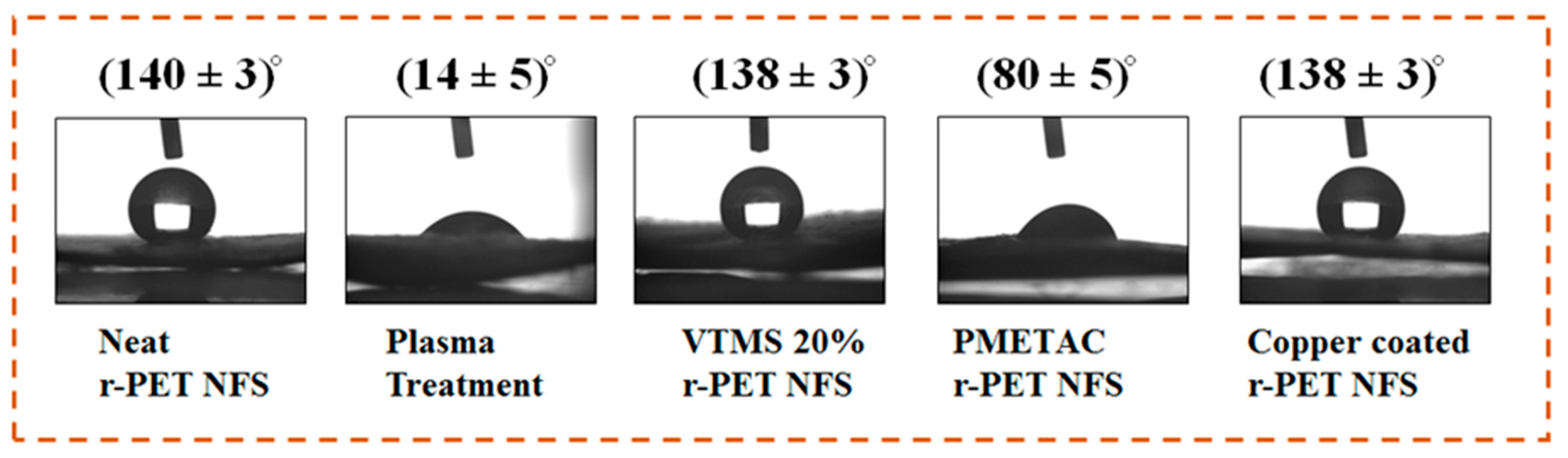
The obtained r-PET nanofibers were hydrophobic, and to create hydroxyl groups before the silanization process, plasma treatment was needed. Previously, plasma treatment was used to create hydroxyl groups on textile substrates [
2]. The r-PET nanofibers were treated with air plasma using Harrick Plasma cleaner PDC-002, and the parameters for plasma treatment are listed below in
Table 1.
2.3.2. Silanization
The plasma treated r-PET nanofibers were placed in an ethanol solution having 10% (v/v) vinyl-tri-methoxy-silane (VTMS) for 20 min. The VTMS-treated r-PET nanofibers were rinsed with DI water and immediately vacuum dried at 50 °C. The successful VTMS treatment provided the hydrophobic surface of r-PET nanofibers due to the presence of dense vinyl groups.
2.3.3. Polymerization
The silanized-treated r-PET nanofibers were immersed into a polymerization solution, which contained a mixture of 20% (v/v) METAC aqueous solution (100 mL) and 60 mg of potassium persulfate (KPS) for 60 min to carry out the polymerization of METAC (PMETAC) brushes while stirring at 60 °C. Finally, the polymerized r-PET nanofibers were washed with DI water and vacuum dried at 50 °C for 2 h.
2.3.4. Electroless Deposition
The electroless deposition (ELD) of copper was carried out on PMETAC r-PET nanofibers by following previous protocols [
20,
22,
23,
24]. Briefly, the PMETAC r-PET nanofibers were immersed in a 5 mM aqueous solution of ammonium tetra-chloro-palladate (II) (NH
4)
2PdCl
4) for 20 min for the ion-exchange reaction. During the ion-exchange, [PdCl
4]
2- catalytic ions were immobilized onto the quaternary ammonium groups of PMETAC polymer chains, and the samples were gently washed with DI water. Further, an ELD bath was prepared to contain Solutions A and B (
Table 2) with a ratio of 1:1, where Solution A consisted of 13 g/L copper sulfate pentahydrate, 12 g/L sodium hydroxide, and 29 g/L potassium sodium tartrate tetrahydrate, while Solution B contained formaldehyde 9.5 mL/L in DI water. A detailed summary of the chemicals used during the fabrication of the conductive r-PET nanofibers is given in
Table 2 and
Table 3.
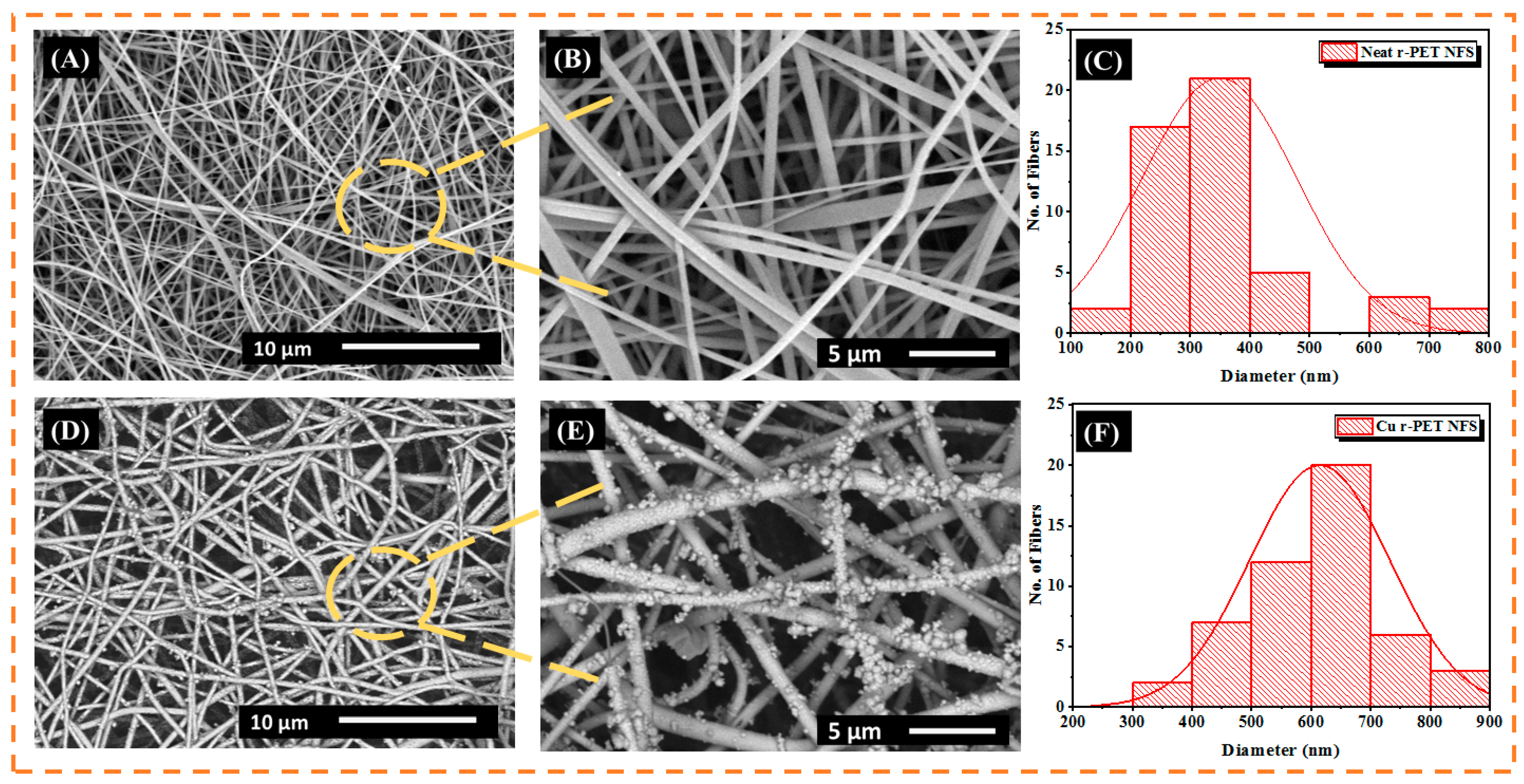
2.4. SEM Morphology
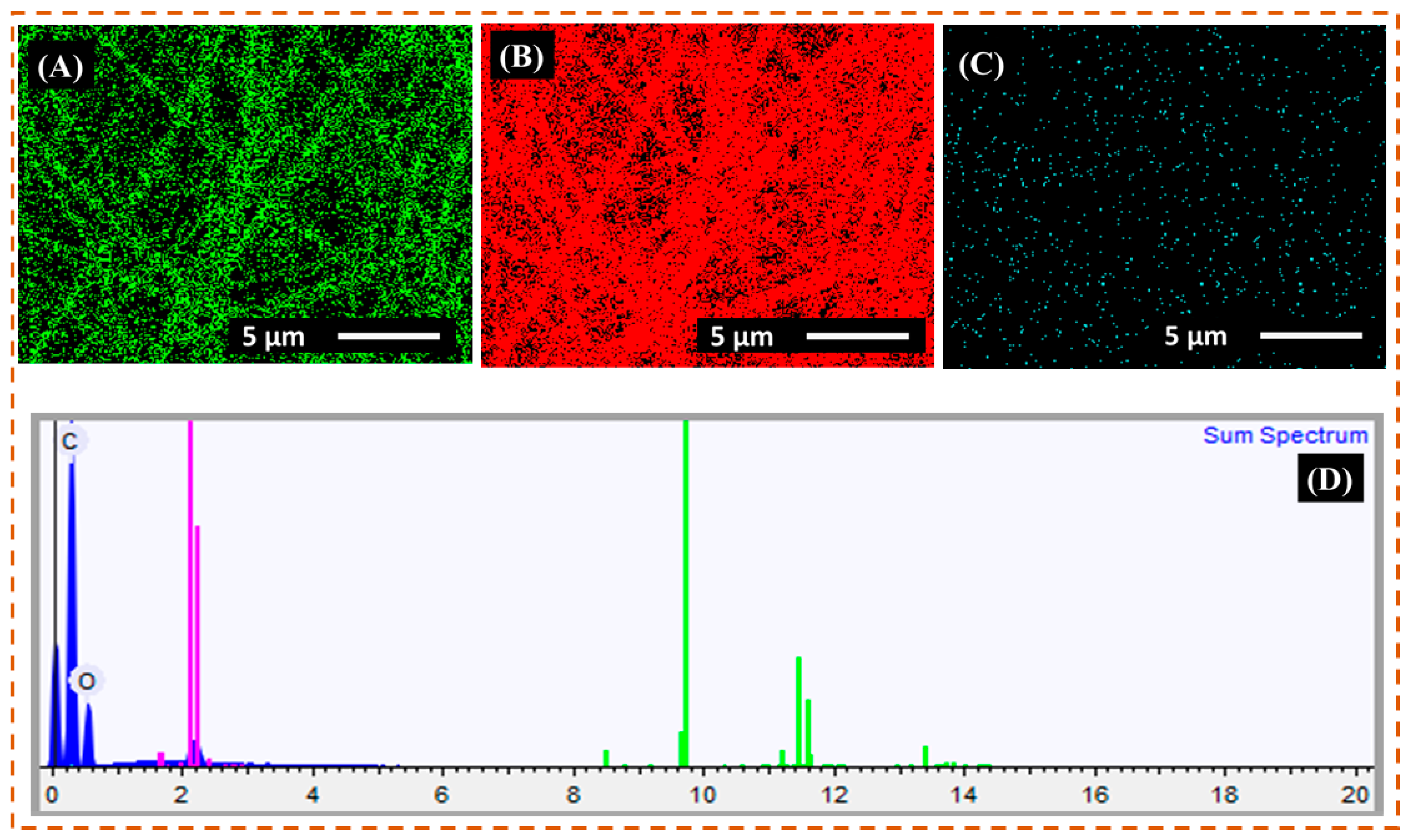
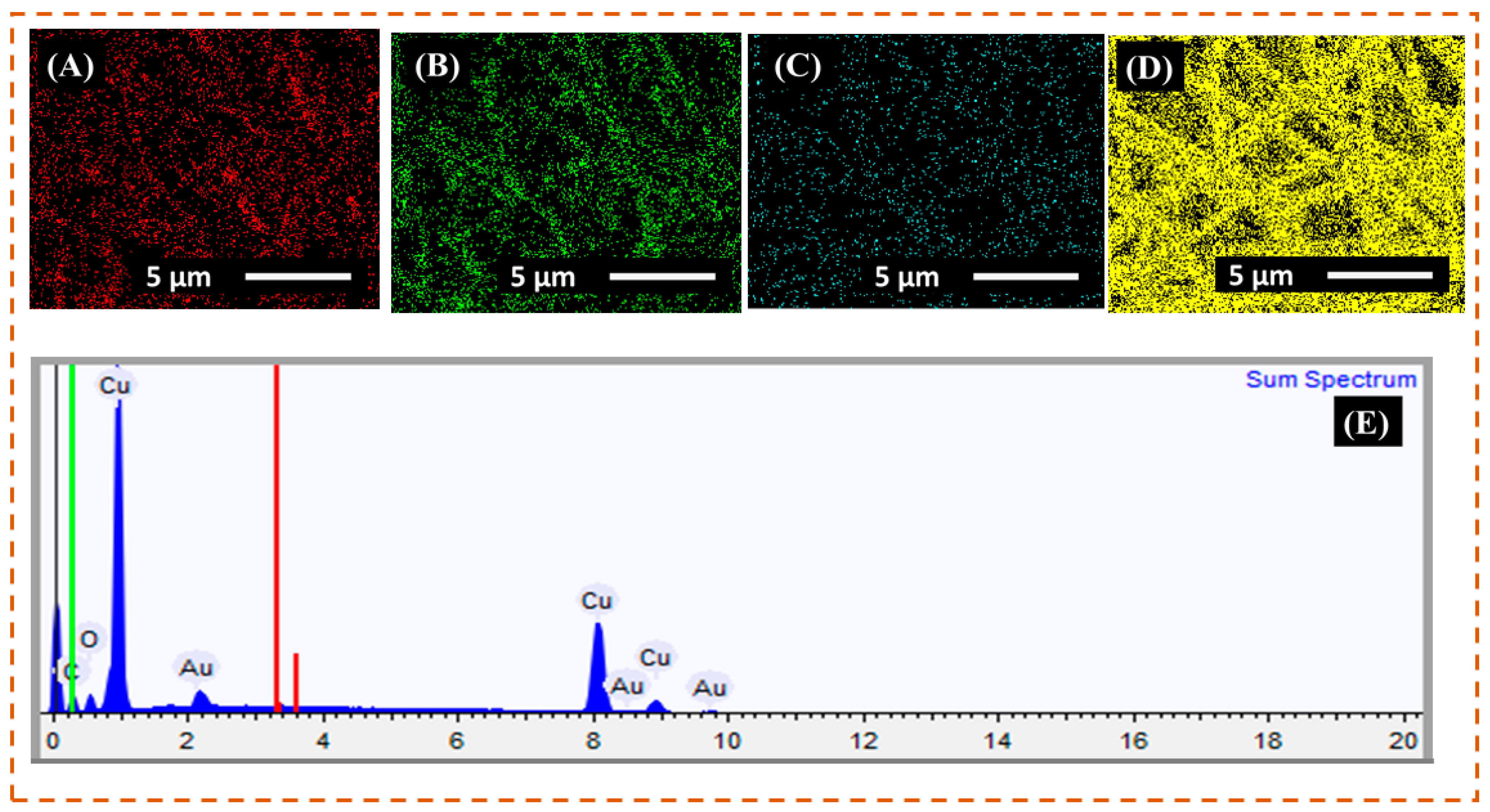
Scanning electron microscopy (S-3000N; Hitachi, Tokyo, Japan) with an acceleration voltage of 30 kV was used to observe the surface morphology of the neat r-PET nanofibers and copper-coated r-PET nanofibers. The EDX images and spectrum were obtained using an S-3000 N, Hitachi Ltd. X-ray spectroscopy, Japan. All samples of SEM and EDX were sputter coated with gold before analysis.
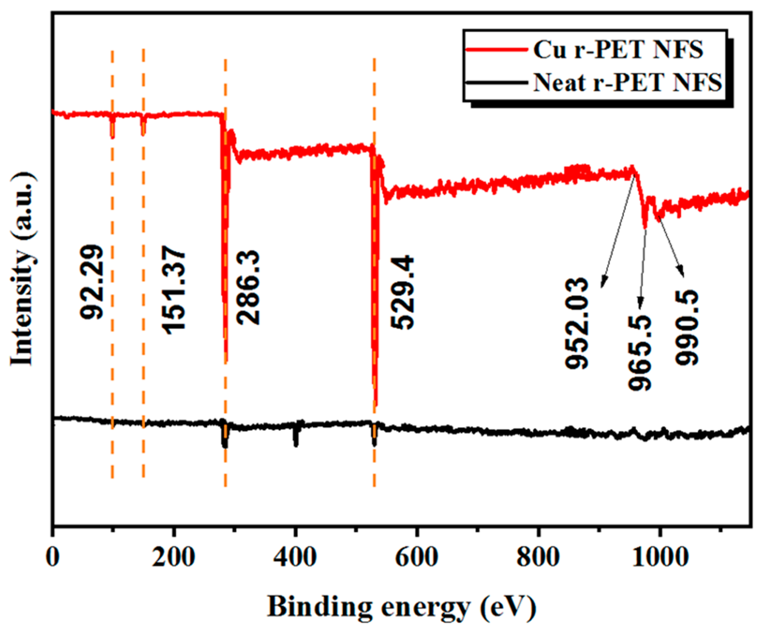
2.5. XPS Analysis
The X-ray spectroscopy (XPS) (S-3000 N, Hitachi, Tokyo, Japan) was performed to analyze the chemical composition of the neat r-PET nanofibers and copper-coated r-PET nanofibers.
2.6. Water Contact Angle
An OCA-40 contact angle instrument (Data physics Filderstadt Germany) was applied to determine the water contact angle of neat r-PET nanofibers and each process involved to fabricate the conductive r-PET nanofibers.
2.7. Tensile Strength Properties
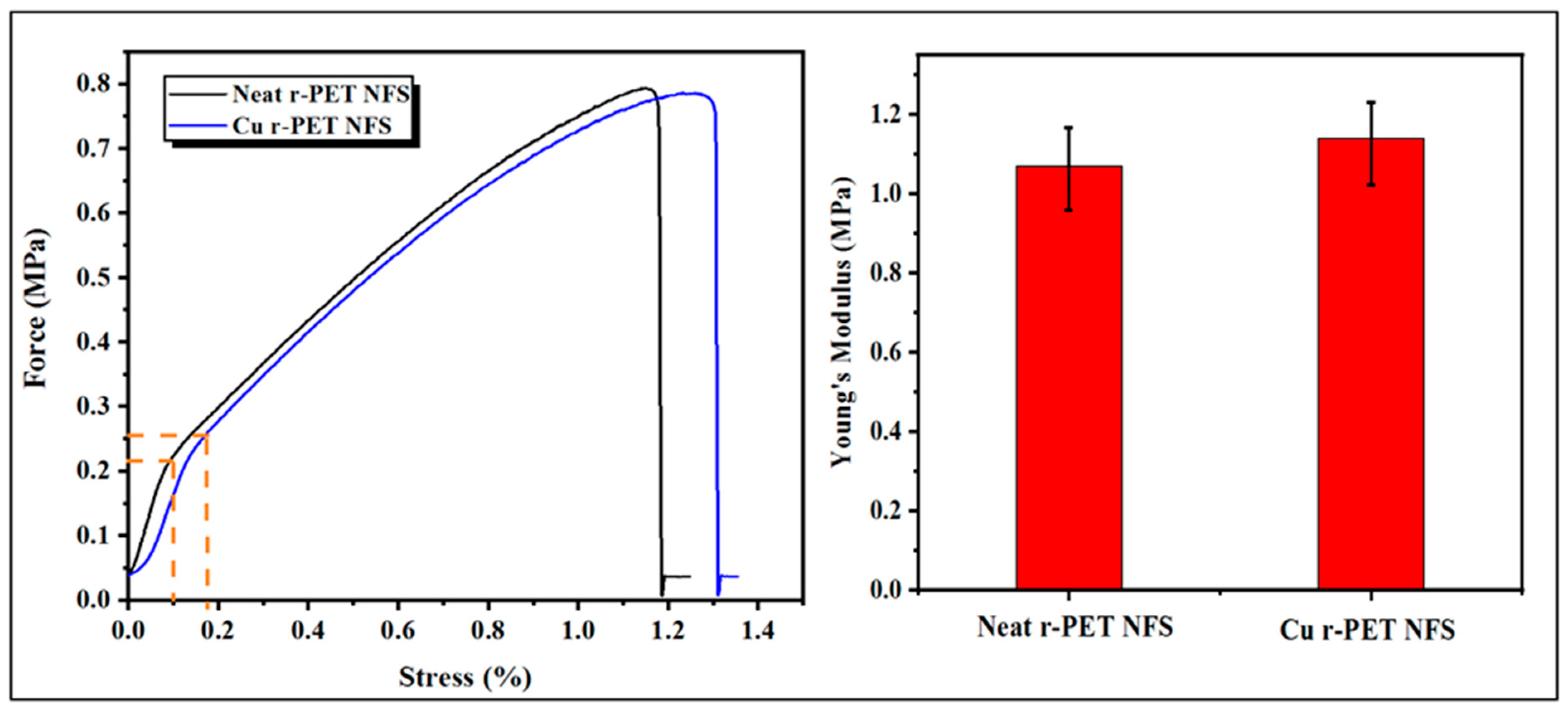
The mechanical properties of neat r-PET nanofibers and copper-coated r-PET nanofibers after the ELD process were tested by a Titan Universal Tester 3-910, Titan Company Ltd., Hessen, Germany. The tensile strength was measured according to the ASTM D-638 standard. During the test, the speed was set at 5.0 mm/min. The values of the stress-strain curves and Young’s modulus were calculated by using the following Equations (1)–(3), respectively [
32].
where ε,
σ, and E represents the stress, strain, and Young’s modulus, respectively.
represent the change in length, and
l shows the original length of the specimen. F is the applied force on the specimen, and A is the area of the specimen.
2.8. Shrinkage Test
The shrinkage test was performed by taking 5 × 5 cm
2 r-PET nanofibers with an average thickness of 120 µm. The shrinkage of r-PET nanofibers after the ELD process was calculated by using Equation (4) for lengthwise shrinkage and Equation (5) for widthwise shrinkage, respectively.
In Equation (4), Ls is lengthwise shrinkage, L is the original length of the samples, and ∆L is the change in the original length after the ELD process. In Equation (5), Ws is widthwise shrinkage. W is the original width of the samples. ∆w is the change in the original width after the ELD process. In Equation (6), Rs is the residual shrinkage after the ELD process.
4. Conclusions
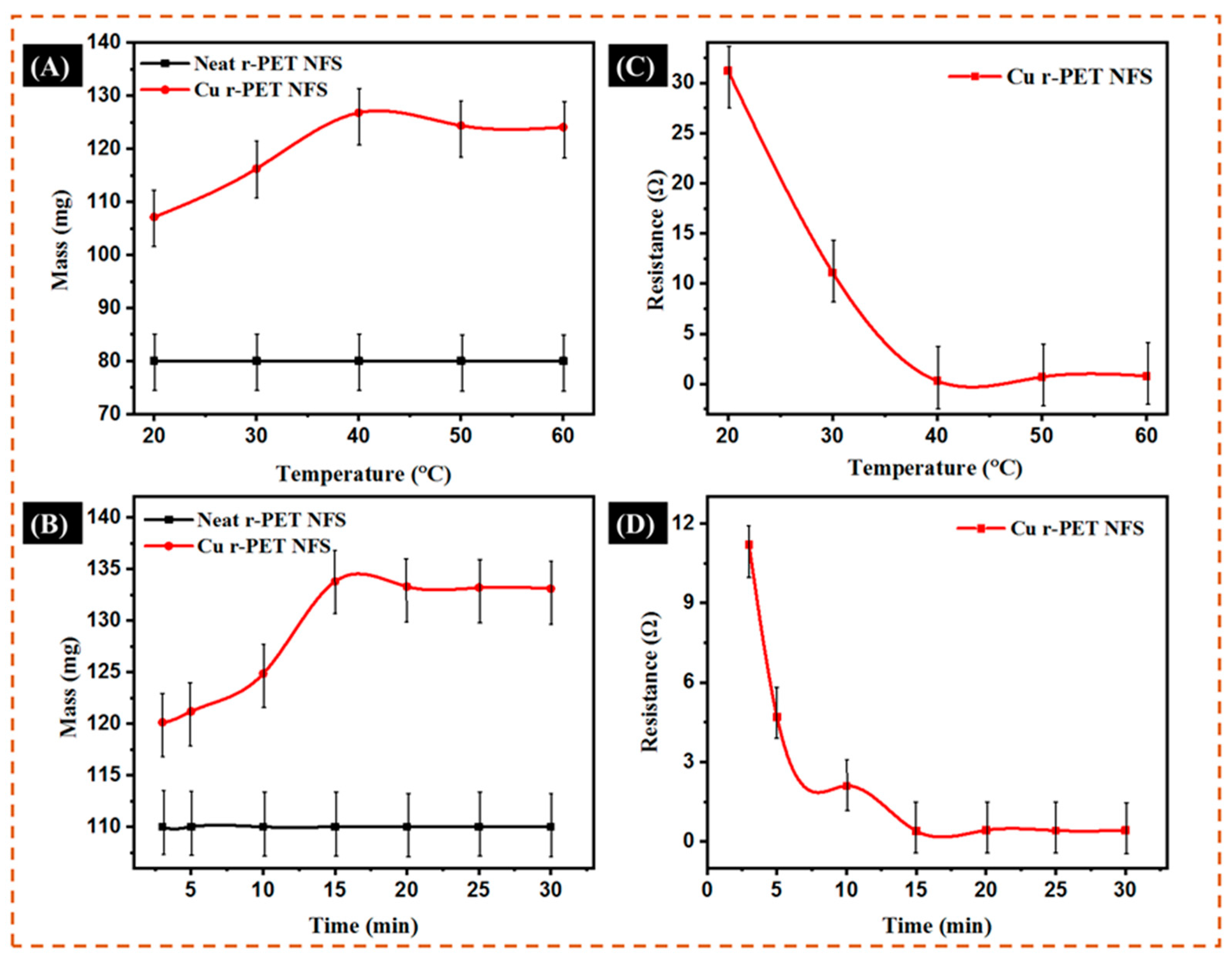
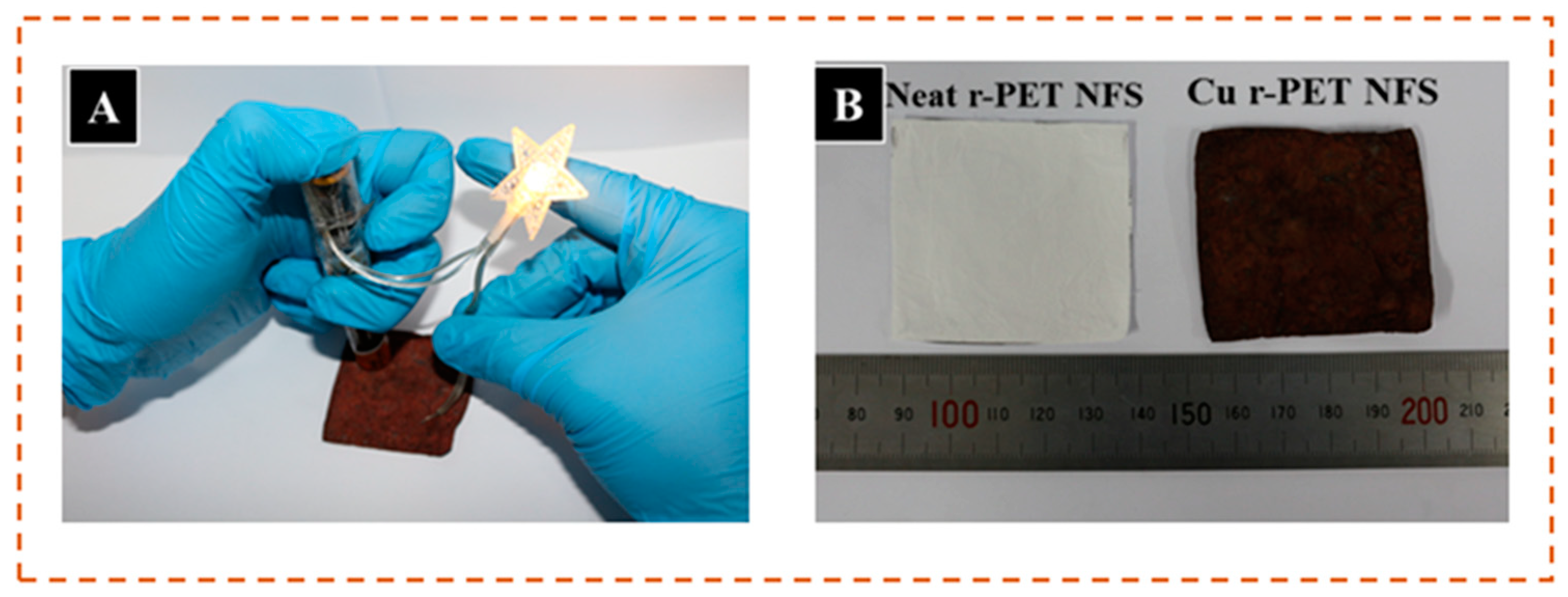
In this research study, copper-coated r-PET nanofibers were successfully fabricated by the process of electroless deposition. The optimized temperature was observed as 40 °C, and the optimized time of 15 min was set for proper copper deposition on the r-PET nanofibers. The SEM images evidently showed the fibrous morphology of the r-PET nanofibers with an average diameter of 350 nm, and the copper-coated r-PET nanofibers retained the fibrous morphology with a slight increase in the average diameter of 700 nm. The optimized copper-coated r-PET nanofibers were composed of 71.6% copper and showed a low electrical resistance of 0.1 Ω. Moreover, the r-PET nanofibers were flexible and showed good mechanical strength. As-prepared, conductive r-PET nanofibers have good potential and could be used in many applications such as wearable electronics, flexible sensors, and energy storage.


 ,
, 


