Review

One-, Two-, and Three-Dimensional Self-Assembly of Atomically Precise Metal Nanoclusters

1
Department of Applied Chemistry, Faculty of Science, Tokyo University of Science, Kagurazaka, Shinjuku-ku, Tokyo 162-8601, Japan
2
Research Institute for Science & Technology, Tokyo University of Science, Shinjuku-ku, Tokyo 162-8601, Japan
3
Photocatalysis International Research Center, Tokyo University of Science, 2641 Yamazaki, Noda, Chiba 278-8510, Japan
*
Author to whom correspondence should be addressed.
Nanomaterials 2020, 10(6), 1105; https://doi.org/10.3390/nano10061105
Submission received: 14 May 2020 / Revised: 26 May 2020 / Accepted: 27 May 2020 / Published: 3 June 2020

Abstract

:
Metal nanoclusters (NCs), which consist of several, to about one hundred, metal atoms, have attracted much attention as functional nanomaterials for use in nanotechnology. Because of their fine particle size, metal NCs exhibit physical/chemical properties and functions different from those of the corresponding bulk metal. In recent years, many techniques to precisely synthesize metal NCs have been developed. However, to apply these metal NCs in devices and as next-generation materials, it is necessary to assemble metal NCs to a size that is easy to handle. Recently, multiple techniques have been developed to form one-, two-, and three-dimensional connected structures (CSs) of metal NCs through self-assembly. Further progress of these techniques will promote the development of nanomaterials that take advantage of the characteristics of metal NCs. This review summarizes previous research on the CSs of metal NCs. We hope that this review will allow readers to obtain a general understanding of the formation and functions of CSs and that the obtained knowledge will help to establish clear design guidelines for fabricating new CSs with desired functions in the future.

1. Introduction

1.1. Metal Nanoclusters for Nanotechnology

Nanotechnology is technology to precisely manufacture small structures. In many countries, nanotechnology is being promoted as a national policy. Progress of nanotechnology allows information and functions to be integrated in smaller spaces, making it possible to manufacture devices with more functions at the same scale. In addition, since nanotechnology makes it possible to integrate the same function in a smaller volume than is the case for current devices, it is expected that devices will be downsized, which will increase their portability. This eliminates the need for the user to be dependent on the device location, which could solve the problems such as crowding and traffic jams and allow users to manage their time more effectively. In addition, the progress of nanotechnology has many advantages, such as saving resources and energy and decreasing waste and environmental damage [1].
Techniques to fabricate small materials can be roughly divided into two categories. One category is top-down methods, in which a desired structure is produced by decreasing the size of a larger substrate (Figure 1). Nanotechnology has been supported by the development of top-down methods. For example, increased functionality and miniaturization of electronic devices have been realized by the progress of top-down techniques. However, when a fine structure is manufactured by using tools (light, electron beam, scanning probe microscope, etc.), it is difficult to manufacture nanostructures with finer accuracy than that of the tools. Therefore, in recent years, bottom-up methods that assemble nanostructures from atoms and molecules have attracted attention (Figure 1) [1].
Metal nanoclusters (NCs), which consist of several, up to about one hundred, metal atoms [1,2,3,4,5,6,7,8,9,10], are nanomaterials that can be synthesized by bottom-up methods. Metal NCs are not only small (<2 nm in size), but they also show physical/chemical properties and functions which are different from those of the corresponding bulk metals [11,12,13,14,15,16,17,18,19,20,21,22,23,24,25,26,27,28,29,30,31,32,33,34,35]. Furthermore, the physical/chemical properties and functions of metal NCs change considerably depending on the number of constituent atoms [36,37,38,39,40,41,42,43,44,45,46,47,48,49,50,51,52,53,54,55,56,57,58,59,60,61,62,63,64,65]. Therefore, if the number of constituent atoms of metal NCs is controlled, it is possible to produce various physical/chemical properties and functions by using only one type of metal element. If several types of elements can be used, it becomes possible to obtain more functionalities [66,67,68,69,70,71,72,73,74,75,76,77,78,79,80,81,82]. For these reasons, metal NCs have been attracting considerable attention as a central material in nanotechnology. In recent years, it has become possible to synthesize such metal NCs precisely at the atomic and molecular level by using thiolate (SR) [2,66], alkyne [59,83], phosphine [9,84,85,86,87,88,89,90,91,92], carbon monoxide [93,94,95,96,97,98,99,100], and dendrimers [7] as protective organic molecules. Investigation of the obtained precise metal NCs has revealed their geometrical structure (aggregation pattern of metal atoms) and the influences of miniaturization [1,2,3,4,5,6,7,8,9,10,11,12,13,14,15,16,17,18,19,20,21,22,23,24,25,26,27,28,29,30,31,32,33,34,35,36,37,38,39,40,41,42,43,44,45,46,47,48,49,50,51,52,53,54,55,56,57,58,59,60,61,62,63,64,65] and alloying [66,67,68,69,70,71,72,73,74,75,76,77,78,79,80,81,82] on the electronic structures and physical/chemical properties of metal NCs. In parallel, research on the applications of the optical properties and catalytic activity of metal NCs is being actively conducted [81,101,102,103,104,105,106,107,108].

1.2. Controlled Assembly of Metal Nanoclusters

As mentioned above, metal NCs show promise as constituent units of functional nanomaterials. Gold (Au) NCs have already been put to practical use in the fields of sensors, catalysts, and paints. On the other hand, at present, electronic devices are manufactured by top-down methods. Therefore, to replace the components of current devices with metal NCs, it is necessary to grow metal NCs to a size that allows their combination with structures manufactured by top-down methods. Moreover, in other applications, the small size of metal NCs often makes them difficult to handle. To realize nanodevices and next-generation materials with the advantageous characteristics of metal NCs, it is essential to establish techniques to assemble metal NCs to a size that makes them easy to handle.
To form a one-dimensional (1D) arrangement of metal NCs, templates [109,110] and host–guest interactions [111] are extremely effective. Two-dimensional (2D) and three-dimensional (3D) arrays of metal NCs can be fabricated by Langmuir–Blodgett [112] and alternate adsorption methods. There are many reports in which metal NCs are arranged in one, two, and three dimensions by using these methods. However, in the structures produced by these methods, the metal NCs are not regularly arranged in a strict sense. Since the conductivity (σ) of metal NCs changes exponentially with the length of the insulating organic ligands [113], the existence of a distribution in the distances between NCs (i.e., the length of the insulating part) is undesirable when applying the assembled metal NCs in electronic devices. Furthermore, although the Langmuir–Blodgett and alternate adsorption methods are suitable for arranging metal NCs in a wide size area, they are not suitable for arranging those in a tiny area.
Metal NCs are regularly arranged in single crystals. Therefore, it is possible to produce precise structures in which metal NCs are regularly connected in one, two, and three dimensions by crystallizing them while including an ingenious means to connect metal NCs. In fact, many crystals in which metal NCs are regularly linked by such a method have been reported in recent years. These structures contain strong bonds, such as Au−Au, Au−silver (Ag), Ag−oxygen (O), Ag−sulfur (S), Ag−chloride (Cl), Ag−nitrogen (N), cesium (Cs)−S, or hydrogen (H) bonds [114], and weak interactions, such as π−π, anion−π, cation···π, aryl CH···Cl, and van der Waals interactions [115] (Figure 2). Similar to supramolecules, molecular assemblies [116], and metal–organic frameworks (MOFs) [117] that are self-assembled from metal ions and organic molecules, connected structures (CSs) of metal NCs can be formed by self-assembly during crystallization, using these bonds and interactions. Such structures, which could also be called “suprametal NC crystals”, exhibit physical/chemical properties different from those of an individual metal NC. Thus, the formation of CSs not only increases the size of the structure, but also enables the application of NCs in new fields.

1.3. Contents of This Review

In recent years, it has become possible to control not only the geometrical structure of metal NCs, but also 1D, 2D, and 3D CSs of metal NCs. Further development of these techniques will lead to novel nanomaterials possessing the characteristics of metal NCs. Such development may enable a future in which metal NCs are applied in devices. However, since these studies have been initiated in recent years, there have been few review articles focusing on 1D, 2D, and 3D CSs of metal NCs [118,119].
In this review, we summarize the existing research, with the purposes of understanding the current situation regarding these structures and giving perspective regarding clear design for producing new 1D, 2D, and 3D CSs with desired functions.
This review is structured as follows. Section 2 outlines the fabrication of 1D CSs consisting of metal NCs, their geometrical structures, and physical/chemical properties. Then, Section 3 and Section 4 present research on 2D and 3D CSs, respectively. After summarizing this review article in Section 5, a brief future outlook is described in Section 6.
It should be noted that 1D, 2D, and 3D CSs of metal NCs can be formed by methods other than crystallization [120,121]; for example, hydrophilic Au NCs have been arranged in 1D and 3D form by the Xie’s group, although these NCs have not been crystallized. However, in this review, only the CSs of metal NCs in crystals are summarized, because our focus is on the regularly CSs in a strict sense. In addition, we described the synthesis methods only for the several examples. Thus, we recommend the readers who want to know the detail of synthesis methods for each example to refer to each original paper.

2. One-Dimensional Structures

The formation of 1D CSs composed of precise metal NCs is important from the viewpoint of the fabrication of controlled nanodevices by bottom-up methods. In this section, we introduce some typical examples of the construction of 1D CSs by the formation of metal−metal bonds (Figure 2A), formation of Ag−O bonds (Figure 2B), control of counterions (Figure 2C), and introduction of linker molecules (Figure 2D). The connection methods, NCs, linkers, year reported, and reference numbers of 1D CSs are summarized in Table 1. Chemical structures of some of the ligands used in these studies are shown in Scheme 1. The chemical structures of organic molecules used as linkers are illustrated in Scheme 2.

2.1. Direct Connection via Metal−Metal Bonds

In 2014, Maran et al. [122] fabricated a 1D CS composed of an SR-protected Au 25-atom NC ([Au25(SR)18]0). Since Au25(SR)18 NCs exhibit high stability among Aun(SR)m NCs, their geometrical/electronic structures and physical/chemical properties have been studied extensively [18,27,123,124,125,126,127,128,129,130,131,132,133,134,135,136,137,138,139]. However, because most of the studies were conducted on Au25(SR)18 in solution and there had been few studies on Au25(SR)18 in the solid phase, Maran’s group studied the behavior of Au25(SR)18 in the solid state.
In their study, butanethiolate (S-Bu, Scheme 1(1)) was used as the SR ligand. First, [Au25(S-Bu)18] anion was synthesized by reducing the Au(I)- S-Bu complex by using sodium borohydride (NaBH4). Then, [Au25(S-Bu)18] anion was oxidized into neutral [Au25(S-Bu)18]0 in open column packed with silica gel, and single crystals were grown by slow evaporation. Figure 3A(a) shows the geometrical structure of [Au25(S-Bu)18]0 obtained by single-crystal X-ray diffraction (SC-XRD). Each [Au25(S-Bu)18]0 has almost the same framework structure as that of [Au25(SR)18]0 protected by other SR ligands; e.g., phenylethanethiolate (PET, Scheme 1(2)) and ethanethiolate (S-Et, Scheme 1(3)) (Figure 3A(b)) [27,53]. However, Au−Au bonds formed between adjacent NCs in the [Au25(S-Bu)18]0 crystal, unlike the case for other [Au25(SR)18]0 crystals (Figure 3A(a),B(a)). This indicates that [Au25(S-Bu)18]0 is a suitable structural unit to form 1D CSs. The Au−Au distance between adjacent NCs of 3.15 Å was within the range of aurophilic interactions (2.9−3.5 Å) and shorter than the non-bonding Au−Au distance (3.80 Å) estimated from the van der Waals radius of Au. This result indicates that a 1D CS was formed in the crystal structure of [Au25(S-Bu)18]0 via Au−Au bonds. To form such a 1D CS, it was considered that the repulsion between the ligands was suppressed and an attractive force between the ligands was induced because the adjacent NCs twisted and approached each other (twist-and-lock mechanism). It was suggested that 1D CSs did not form when S-Et and PET were used (Figure 3A(b),B(b)) because S-Et has a short alkyl group that leads to a weak attractive force between ligands and PET with a bulky functional group has large steric repulsion between ligands. In 2017, these researchers also succeeded in forming a 1D CS of [Au25(S-Pen)18]0 (S-Pen = pentanethiolate, Scheme 1(4)) [140]. In the same paper, they reported that the distance between NCs was shorter in this 1D CS than in the 1D CS of [Au25(S-Bu)18]0 (Figure 3C). In addition, in 2019, they formed 1D CSs of [Au24Hg(S-Bu)18]0 (Hg = mercury) and [Au24Cd(S-Bu)18]0 (Cd = cadmium), in which one Au of [Au25(S-Bu)18]0 was replaced with Hg or Cd [141].
The same group also revealed that the 1D CSs had electronic structures and physical properties different from those of individual NCs. Since [Au25(S-Bu)18]0 has unpaired electrons, it exhibits paramagnetism in solution. Conversely, the 1D CS of [Au25(S-Bu)18]0 was non-magnetic (Figure 3D) [122]. This change was mainly ascribed to the formation of the 1D CS, which led to the close proximity of NCs, allowing the unpaired electrons of adjacent NCs to form electron pairs. Because of the formation of such electron pairs, the conduction band of the 1D CS was full and its valence band was empty, so the obtained 1D CS was predicted to have the properties of a semiconductor [122].
In 2020, we [142] conducted a detailed study on the factors responsible for the formation of 1D CSs via Au−Au bonds by using [Au4Pt2(SR)8]0 (Pt = platinum) as the NC. A similar NC, [Au4Pd2(PET)8]0 (Pd = palladium), was reported by Wu and colleagues in 2017 (Figure 4) [143]. Although it was not mentioned in their paper, [Au4Pd2(PET)8]0 formed a 1D CS in its crystal (Figure 4). Because this type of metal NC has a smaller metal core than that of [Au25(SR)18]0 described above (Figure 4), the distribution of the ligands in this type of NC should change depending on the ligand structure. Moreover, Au and Pt form a stronger bond than that between Au and Pd [144]. Therefore, it was expected that changing Pd to Pt would increase the stability of the NC [145], thereby expanding the variety of ligand functional group structures that can be used in 1D CSs. For these reasons, we chose [Au4Pt2(SR)8]0 as the building block of their 1D CS. The SR ligands shown in Scheme 1(2),(5)–(8) were used. Because the functional group structures of these SR ligands differ greatly, it was expected that there would be different ligand–ligand interactions between the resulting NCs.
In the experiment, [Au4Pt2(SR)8]0 NCs with different SRs were precisely synthesized by reducing the metal−SR complex with NaBH4. Each [Au4Pt2(SR)8]0 NC was separated from by-products, using open column chromatography, and then single crystals were grown by vapor diffusion. The SC-XRD of the series of [Au4Pt2(SR)8]0 crystals revealed the following three points for [Au4Pt2(SR)8]0: (1) [Au4Pt2(SR)8]0 is a metal NC that can become a structural unit of 1D CSs via Au−Au bond formation (Figure 5A); (2) although all [Au4Pt2(SR)8]0 NCs have similar structures, the intra-cluster ligand interactions vary depending on the ligand structure. As a result, the distribution of the ligands in [Au4Pt2(SR)8]0 changes depending on the ligand structure; (3) the differences in the ligand distributions influence the inter-cluster ligand interactions, which in turn affect the formation of 1D CSs and change their structure (Figure 5B). These results demonstrate that we need to design intra-cluster ligand interactions, to produce 1D CSs with desired configurations. This study also explored the effects of 1D CS formation on the electronic structure of NCs. The results revealed that the formation of the 1D CS caused the band gap of the NCs to decrease (Figure 5C,D) [142].
Zhang et al. also very recently reported the formation of 1D CS consisting of the (AuAg)34(A-Adm)20 alloy NCs (A-Adm = 1-ethynyladamantane; Scheme 1(9)) [146]. For (AuAg)34(A-Adm)20 alloy NCs, either monomeric NC or 1D CSs were formed depending on the solvent. Monomeric NC could be converted to 1D CSs by dissolving in an appropriate solvent. In the 1D CS, NCs were connected each other via Ag−Au−Ag bond (Figure 6A,B). They studied the electronic structure of the obtained 1D CS by density functional theory (DFT) calculations, which predicted that the single crystals of 1D CS have a band gap of about 1.3 eV (Figure 6C). Field-effect transistors (FETs) fabricated with single crystals of 1D CS (Figure 6D) showed highly anisotropic p-type semiconductor properties with ~1800-fold conductivity in the direction of the polymer as compared to cross directions (Figure 6E), hole mobility of ≈0.02 cm2/Vs, and an ON/OFF ratio up to ~4000. They noted that the conductivity (1.49 × 10⁻⁵ S/m) of these crystals in the c-crystallographic axis is one-to-three orders of magnitude higher than the values reported for 1D CS consisting of Au21 clusters, where 1D CS was formed by modulating the weak interactions in the ligand layers (see Section 2.3). It was interpreted that the conductivity and charge carrier mobility was increased by several orders of magnitude in their 1D CS via direct linking of the metal NCs by the –Ag–Au–Ag– chains in the crystal. They described in this paper that this result holds promise for further design of functional cluster-based materials with highly anisotropic semiconducting properties.

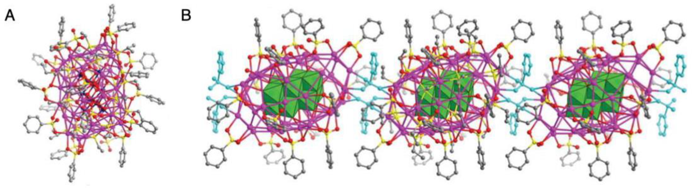
2.2. Connection via Ag−O Bonds

When Ag NCs contain acetic acid ions (CH3COO), trifluoroacetic acid ions (CF3COO), or nitrate ions (NO3) in the ligand layer, it is possible to connect Ag NCs by forming Ag−O bonds. Su et al. [147] first reported the formation of such a 1D CS in 2014. In this study, the 1D CS was obtained by crystallization of the product which was obtained by the reaction between AgS-tBu, (NH4)3[CrMo6O24H6] (Cr = chromium, Mo = molybdenum), Ni(CH3COO)2 (Ni = nickel), AgCF3COO, and AgBF4. The each Ag NC had a chemical composition of Ag20(CO3)(S-tBu)10(CH3COO)8(DMF)2 (CO32− = carbonate anion; S-tBu = tert-butylthiolate, Scheme 1(10), DMF = N,N-dimethylformamide). The Ag20(CO3) core of the NC was formed by the aggregation of Ag around CO32− (Figure 7A) as an anion template. In the crystal, the Ag NCs were connected in one dimension via two Ag−O−Ag bonds (Figure 7B). The obtained 1D CS was stable in both solid and solution states, had a bandgap of 3.22 eV, and exhibited reversible thermochromic emission.
Formation of 1D CSs based on a similar principle was also reported by Mak and co-workers in 2017 [148]. In their report, Ag18(CO3)(S-tBu)10(NO3)6(DMF)4 was linked by the formation of Ag−O bonds (Figure 8). The Ag18(CO3) core contained CO32− as an anion template at the center, like Ag20(CO3). As described in Section 3.1, this group also succeeded in forming a 2D CS of Ag20(CO3) by changing the SR structure.
Recently, Sun et al. [149] succeeded in the connection of Ag44(V10O28)(S-Et)20(PhSO3)18(H2O)2 (V10O286−, Scheme 1(11), PhSO3 = benzenesulfonic acid ion). In this 1D CS, the Ag44(V10O28) core was formed by using the polyoxometalate (POM) V10O286− as an anion template (Figure 9A). This was the first report of the formation of a structure in which V10O286− was covered with an Ag NC with SR as a ligand. This 1D CS assembled because two Ag−O bonds were formed between two PhSO3 in the ligand layer and one Ag44(V10O28)(S-Et)20 NC (Figure 9B).
In the 1D CS of [Au7Ag9(dppf)3(CF3COO)7BF4]n (dppf = 1,1′-bis(diphenylphosphino)ferrocene, Scheme 1(12), BF4 = tetrafluoroboric acid) reported by Wang et al. [150] in 2019, each NC was also connected via an Ag−O bond (Figure 10A), although this was not direct connection of metal NCs. In the above three NCs (i.e., Ag20(CO3)(S-tBu)10(CH3COO)8(DMF)2, Ag18(CO3)(S-tBu)10(NO3)6(DMF)4, and Ag44(V10O28)(S-Et)20(PhSO3)18(H2O)2), the anion template was contained in the center, whereas Au7Ag8(dppf)3(CF3COO)7 had an icosahedral metal core composed of Au7Ag8. Such an icosahedral core structure is often seen in metal NCs [27,53]. The 1D CS of [Au7Ag9(dppf)3(CF3COO)7BF4]n was synthesized in one pot. Probably, excess Ag binds to CF3COO in the ligand layer during synthesis, resulting in the formation of a 1D CS composed of Au7Ag8(dppf)3(CF3COO)7 NCs. The researchers also revealed that this 1D CS possessed a band gap of 2.18 eV (Figure 10B).

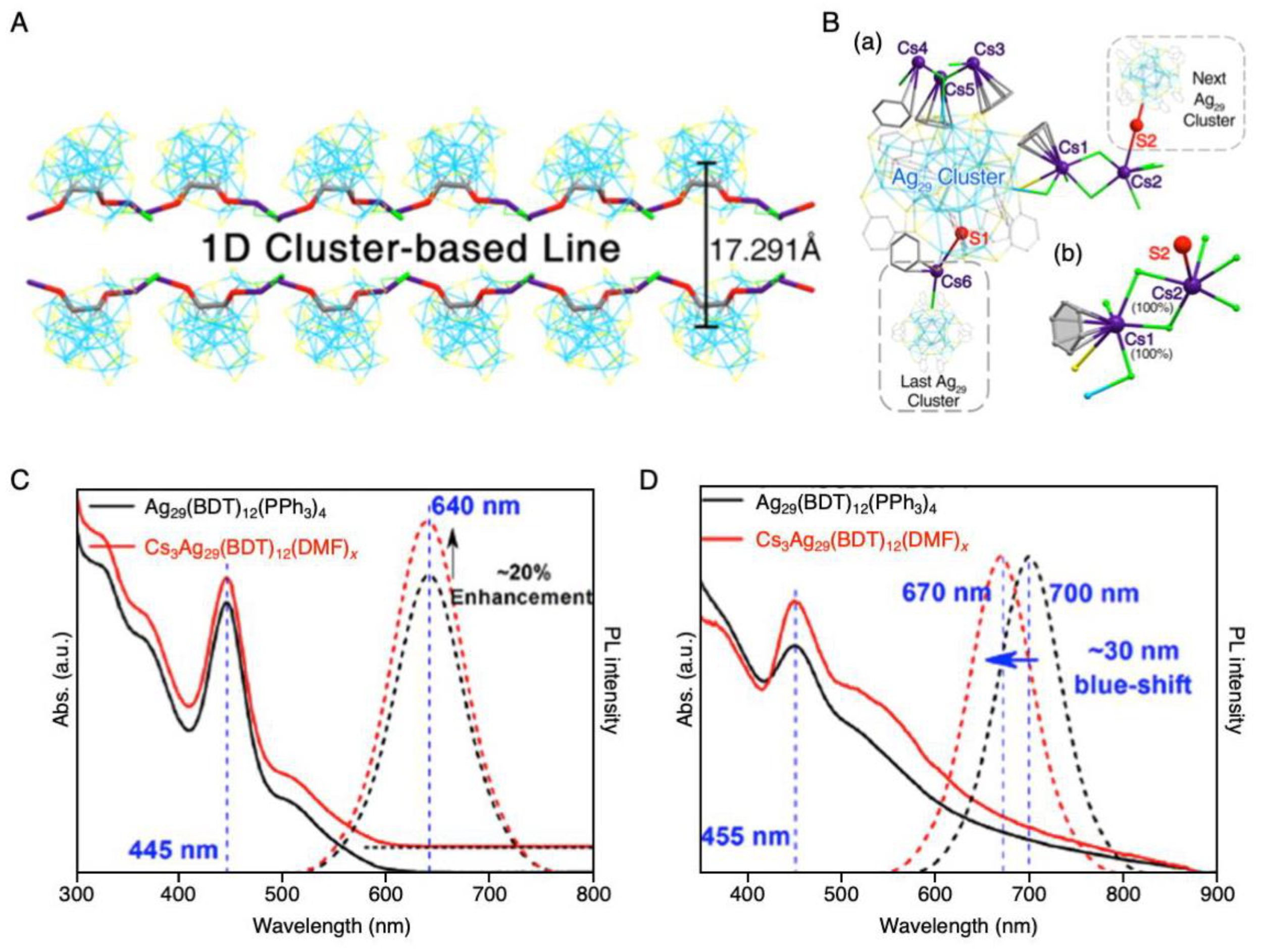
2.3. Control of Counterions

For certain metal NCs, the total number of valence electrons satisfies the number for the closed-shell electronic structure when it is a cation, so they are generated as a cation [151]. For example, [Au21(S-c-C6H11)12(DPPM)]+ (S-c-C6H11 = cyclohexanethiolate, Scheme 1(13), and DPPM = bis(diphenylphosphinomethane), Scheme 1(14)) is synthesized as a cation. In 2018, Jin et al. [152] revealed that [Au21(S-c-C6H11)12(DPPM)]+ formed a 1D CS in a crystal by assembling as a pair with the counter anion and that the structure of the 1D CS changed depending on the counterion (Figure 11A,B).
In this study, [Au21(S-c-C6H11)12(DPPM)2]+[AgCl2] and [Au21(S-c-C6H11)12(DPPM)2]+[Cl] were precisely synthesized and single crystals were grown. As shown in Figure 11B, a 1D CS was formed by the alternating connection of [Au21(S-c-C6H11)12(DPPM)2]+ and [AgCl2] in the [Au21(S-c-C6H11)12(DPPM)2]+[AgCl2] crystal. This 1D CS was considered to assemble via π-π, anion-π, and aryl C-H···Cl interactions. The connection pattern of [Au21(S-c-C6H11)12(DPPM)2]+ in the 1D CS changed slightly when the counterion was Cl rather than [AgCl2]. It was considered that the connection pattern of [Au21(S-c-C6H11)12(DPPM)2]+ changed because the arrangement of phenyl groups in the NC was affected by the counterion (Figure 11A).
The obtained 1D CSs of [Au21(S-c-C6H11)12(DPPM)2]+ had different electron transport properties depending on the counter anion. The 1D CS of [Au21(S-c-C6H11)12(DPPM)2]+[AgCl2] had a σ of only ~1.44 × 10⁻⁸ S/m, whereas that of [Au21(S-c-C6H11)12(DPPM)2]+[Cl] was σ ~2.38 × 10⁻⁶ S/m (Figure 11C). Changing the counter anion from [AgCl2] to [Cl] shortened the distance between NCs from 16.80 to 16.39 Å and formed an intra-cluster π-stacking structure that allowed electricity to flow easily (Figure 11B). These two reasons explained why σ of [Au21(S-c-C6H11)12(DPPM)2]+[Cl] was two orders of magnitude higher than that of [Au21(S-c-C6H11)12(DPPM)2]+[AgCl2] (Figure 11D).
There are not only metal NCs synthesized as cations but also metal NCs synthesized as anions. Because the total number of valence electrons of [Ag29(BDT)12(PPh3)4]3− (BDT = 1,3-benzenedithiolate, Scheme 1(15); PPh3 = triphenylphosphine, Scheme 1(16)) satisfies the number for a closed-shell electronic structure as the anion, it is generated as the anion [153]. In 2019, Zhu et al. [154] reported that mixing this NC with Cs acetate in DMF induced Cs+ attachment to the NC and PPh3 desorption from the NC, resulting in the formation of [Cs3Ag29(BDT)12(DMF)x]0 (x = 5 or 6) and that the obtained [Cs3Ag29(BDT)12(DMF)x]0 formed a 1D CS in its crystal. Figure 12A shows the resulting 1D CS. In the crystal, [Cs3Ag29(BDT)12(DMF)x]0 was connected by a series of bonds consisting of −Cs+−DMF−Cs+−S−Ag−Ag−S−. This 1D CS was considered to be formed because of the electrostatic attraction between [Ag29(BDT)12(DMF)x]3− and Cs+, Cs−S bond formation, and Cs···π interactions (Figure 12B).
Both [Ag29(BDT)12(PPh3)4]3− and [Cs3Ag29(BDT)12(DMF)x]0 solutions showed similar absorption and photoluminescence (PL) spectra (Figure 12C). This indicates that Cs+ attachment and PPh3 desorption did not markedly change the electronic structure of the Ag29(BDT)12 NCs. In contrast, the absorption and PL spectra of [Ag29(BDT)12(PPh3)4]3- and [Cs3Ag29(BDT)12(DMF)x]0 in the crystalline state were quite different (Figure 12D). The 1D CS of [Cs3Ag29(BDT)12(DMF)x]0 was considered to show different optical behavior from that of the individual [Ag29(BDT)12(PPh3)4]3− because of the electronic interactions between adjacent NCs in the 1D CS of [Cs3Ag29(BDT)12(DMF)x]0.

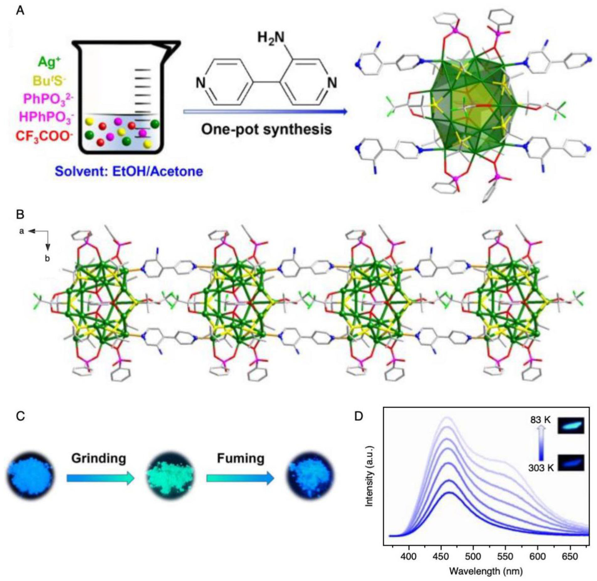
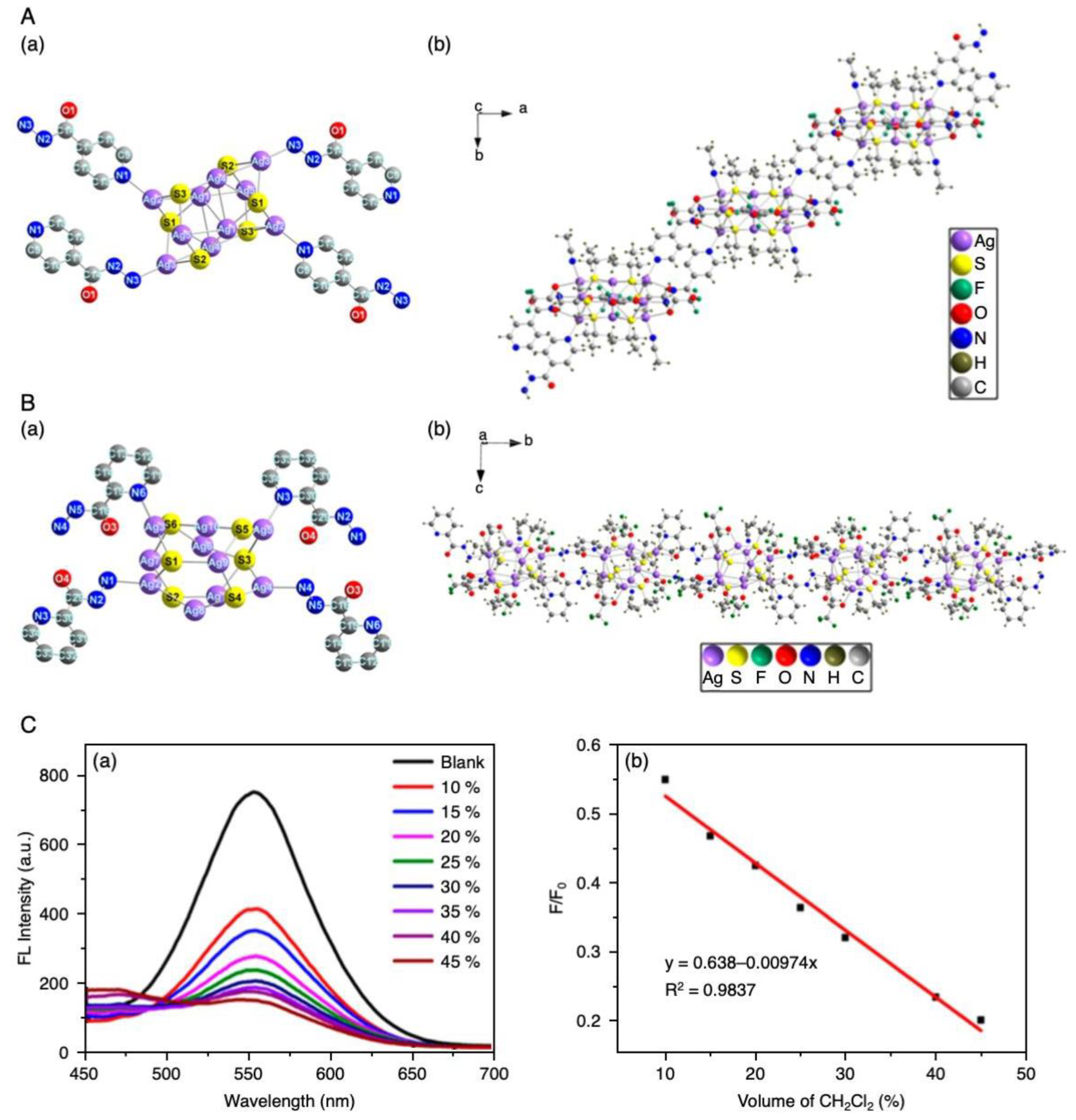
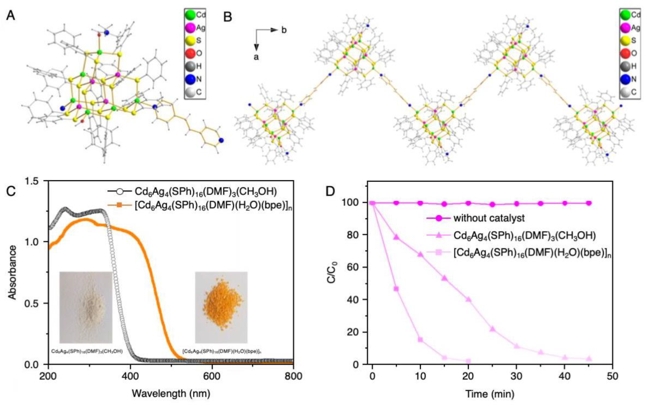
2.4. Introduction of Linker Molecules

In the examples described in Section 2.3, 1D CSs were formed by the counterion acting as a linker. When an organic molecule is used as the linker, the distance between NCs in a 1D CS can be freely controlled because the design of the structure of organic molecules is well understood. In fact, the geometry of an MOF is controlled by the design of the linker organic molecule [155]. In recent years, several 1D CSs of metal NCs with organic molecules as linkers have also been reported.
For example, in 2018, Zang et al. [156] reported a 1D CS in which Ag14(DT-o-C)6 NCs (DT-o-C = 1,2-dithiolate-o-carborane, Scheme 1(17)) were linked by pyrazine (Scheme 2(1)). In this study, first, [Ag14(DT-o-C)6(pyridine/p-methylpyridine)8] (Scheme 2(2),(3)) were identified as Ag NCs with high thermal stability that maintained their framework structure even at 150 °C or higher in air (Figure 13A). Then, they attempted to synthesize Ag NCs in which the pyridine or p-methylpyridine ligands of these Ag NCs were replaced by pyrazine. As a result, they obtained a 1D CS in which Ag14(DT-o-C)6 NCs were linked by pyrazine (Figure 13B). In the obtained structure, pyrazine was coordinated to each Ag14(DT-o-C)6 NC at a diagonal position, which caused the 1D CS to rotate in the clockwise direction with respect to the (001) axis. In this study, the researchers also succeeded in forming 2D and 3D CSs composed of Ag14(DT-o-C)6 NCs by changing the structure of the bipyridine ligand, as described later in Section 3.2 and Section 4.3, respectively.
Because N readily coordinates to Ag, bipyridine is often used to connect NCs containing Ag. In 2019, Zang and colleagues formed a 1D CS composed of Ag18(PhPO3)(S-tBu)10(CF3COO)2(PhPO3H)4 (PhPO32− = phenylphosphinic diion; PhPO3H = phenylphosphinic acid ion) NC nodes with bipyridine(3-amino-4,4′-bipyridine (bpy-NH2, Scheme 2(4)) linkers [157]. In this experiment, NC synthesis, ligation, and crystallization were performed simultaneously in one pot (Figure 14A). The node Ag18(PhPO3)(S-tBu)10 NCs contained PhPO32− as an anion template in their center. In the crystal, adjacent Ag18(PhPO3)(S-tBu)10 NCs were linked by two bpy-NH2 to form a 1D CS (Figure 14B).
The obtained 1D CS was stable up to 110 °C in a nitrogen (N2) atmosphere. When mechanical stimulation was applied to the 1D CS, its PL wavelength changed. When the 1D CS sample subjected to mechanical stimulation was recrystallized, its PL wavelength returned to the original value (Figure 14C). Thus, the PL of the 1D CS composed of Ag18(PhPO3)(S-tBu)10 NCs exhibited reversible mechanochromism. Because this 1D CS emitted light at two wavelengths and its PL intensity ratio changed with temperature (thermochromism; Figure 14D), the authors suggested that this 1D CS could be applied as a thermometer.
In 2019, Bakr et al. [158] also reported the connection of Ag NCs by bipyridine. In this study, a 1D CS was synthesized in one pot (Figure 15A). Ag15Cl(S-tBu)8(CF3COO)5.67(NO3)0.33(DMF)2 was used as the node, and 4,4’-bipyridine (bpy, Scheme 2(5)) was used as the linker. In Ag15Cl(S-tBu)8(CF3COO)5.67(NO3)0.33(DMF)2, Clacted as an anion template. The core of the Ag15Cl NC had a geometry in which one Ag was lost from the Ag16Cl core of the Ag16Cl(S-tBu)8(CF3COO)7(DMF)4(H2O) NC, which did not form a 1D CS, namely individual Ag16Cl(S-tBu)8(CF3COO)7(DMF)4(H2O) NCs (Figure 15B). The 1D CS with a ladder structure was formed by combining these Ag15Cl NCs with three adjacent Ag15Cl NCs via four bpy molecules (Figure 15C). It was found that the 1D CS displayed slightly higher thermal stability than that of the Ag16Cl NCs (Figure 15D).
In the above three studies, the bipyridines had a rigid framework structure. In 2019, Cao et al. formed 1D CSs of Ag NCs by using pyridine derivatives (p-iah = 4-pyridine carboxylic hydrazide, Scheme 2(6); o-iah = 2-carboxylic hydrazide, Scheme 2(7)) that contained N in both the rigid pyridine framework and flexible substituents [159]. In this study, the 1D CSs were obtained by reacting Ag12(S-tBu)6(CF3COO)6(CH3CN)6 (CH3CN = acetonitrile) with the above-mentioned pyridine derivatives. The SC-XRD analysis of the products revealed that Ag10(CF3COO)4(S-tBu)6(CH3CN)2 and Ag10(CF3COO)4(S-tBu)6(CH3CN) were the nodes in the 1D CSs with p-iah and o-iah, respectively (Figure 16A(a),B(a)). These 1D CSs containing p-iah and o-iah had cross-helical and parallel chain structures, respectively (Figure 16A(b),B(b)). The latter structure also contained hydrogen bonds (N−H···O) between the parallel linker molecules. It is interesting that different 1D CSs formed depending on the position of N in the linker molecule (Scheme 2(6),(7)).
Both 1D CSs showed PL and that with o-iah as the linker exhibited weak green PL in highly polar solvents and strong yellow PL in solvents with low polarity. Based on these characteristics, the authors suggested that the 1D CS with o-iah could be used to measure the concentration of dichloromethane (CH2Cl2, Figure 16C) or trichloromethane (CHCl3) in tetrachloromethane (CCl4).
Bipyridines can also be used as linkers to form 1D CSs of Ag chalcogenide NCs. Very recently, Xu and co-workers reported the formation of a zigzag-type of 1D CS with Cd6Ag4(S-Ph)16(DMF)(H2O) (S-Ph = benzenethiolate, Scheme 1(18) and Figure 17A) as a node and trans-1,2-bis(4-pyridyl)ethylene (bpe, Scheme 2(8)) as a linker (Figure 17B) [160]. This 1D CS was obtained by the reaction of Cd6Ag4(S-Ph)16(DMF)3(CH3OH) (CH3OH = methanol) with bpe. In the obtained 1D CS, N of bpe coordinated to Cd not Ag (Figure 17A). Such a coordination pattern has also been observed in 2D and 3D CSs composed of Cd6Ag4(S-Ph)16 and bpe previously reported by Zhang et al. [161,162].
They compared the electronic structures of the resulting 1D CS and individual Cd6Ag4(S-Ph)16(DMF)3(CH3OH) NCs. The results revealed that the band gap of the NCs was narrowed by the formation of the 1D CS (Figure 17C). In the 1D CS, the optical absorption onset was redshifted to the visible region. They used the 1D CS as a visible light (>420 nm)-responsive photocatalyst to decompose the organic dye Rhodamine B in water. The 1D CS exhibited higher photocatalytic activity toward Rhodamine B degradation than that of the Cd6Ag4(S-Ph)16 NCs (Figure 17D) and high stability during the photocatalytic reaction.

3. Two-Dimensional Structures

To date, Ag NCs have been used as the building blocks in almost all 2D CSs. Like Au NCs, Ag NCs have unique electronic and optical properties [68,163,164,165,166] and are expected to be applied in various fields. However, Ag NCs are less stable than Au NCs against external stimuli, such as light and solvents. Therefore, studies have been actively conducted to improve the stability of Ag NCs by assembly of CSs and thereby improve their physical properties. In Section 3.1 and Section 3.2 we focus on the connection of NCs by Ag−O bond formation (Figure 2B) and introducing linker molecules (Figure 2D), respectively. Table 2 summarizes the connection methods, NCs, linkers, reported years, and reference numbers of the relevant literature. Several of the ligands used in these studies are shown in Scheme 1. The organic molecules used as linkers are depicted in Scheme 2.

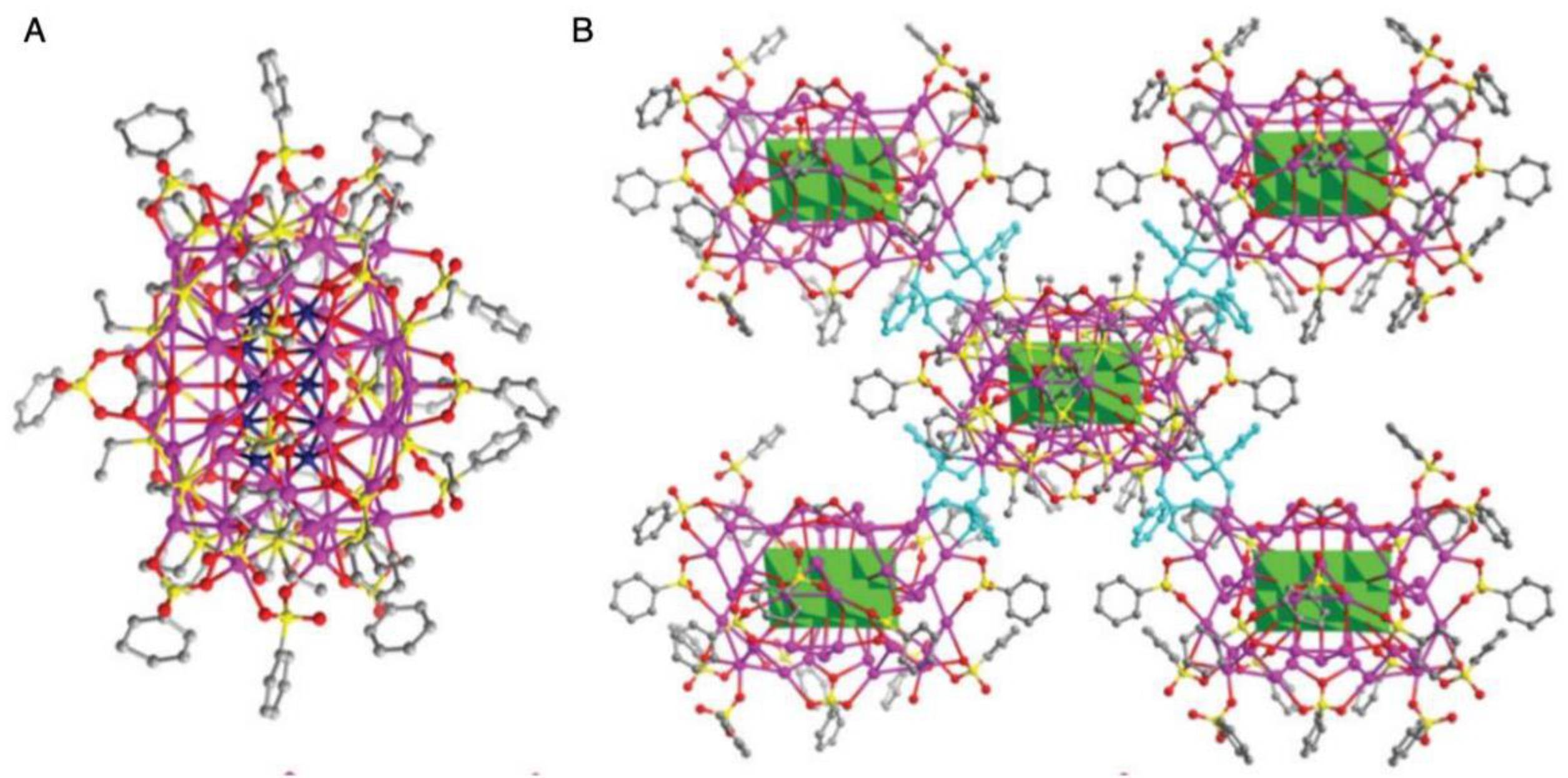
3.1. Connection via Ag−O Bonds

In 2017, Mak et al. [148] reported the formation of 2D CSs with Ag20(CO3)(S-iPr)10(CF3COO)9(CF3COOH)(CH3OH)2 (S-iPr = isopropylthiolate, Scheme 1(5)) or Ag20(CO3)(S-c-C6H11)10(CF3COO)10(CF3COOH)2(H2O)2 as building blocks in their paper on the formation of 1D CSs. These NCs contained CO32− as an anion template at the center of their cores (Figure 18A,B). The structures of the SR in these two types of Ag20(CO3)(SR)10 NCs were different (S-iPr vs. S-c-C6H11), which influenced the formation angle and bond distance between adjacent NCs in the 2D CSs. The O of CF3COO and Ag of an adjacent NC were directly linked via an Ag−O bond with a length of 14 Å. In addition, isolated Ag was trapped between CF3COO of adjacent NCs, so the adjacent NCs were connected via an O−Ag−O bond with a length of 17 Å. The 2D CS consisting of Ag20(CO3)(S-iPr)10(CF3COO)9(CF3COOH)(CH3OH)2 showed dual emission at room temperature. Because both zero-dimensional [Ag20(S-tBu)10(CF3COO)2]Cl·(CF3COO)7·5CH3OH NCs and the 1D CS of Ag20(CO3)(S-tBu)10(CH3COO)8(DMF)2 emit only single emission peaks, it was speculated that the formation of the 2D CS was related to the observed dual emission.
In 2019, Sun and co-workers also reported the formation of a 2D CS, using Ag NCs [149]. In this study, a 2D CS consisting of Ag46(V10O28)(S-Et)23(PhSO3)15(CO3) was formed (Figure 19), using a different solvent from the case of Ag44(V10O28)(S-Et)20(PhSO3)18(H2O)2, which formed a 1D CS (Figure 9). These Ag NCs have the same total number of ligands (S-Et and PhSO3) of 38 but different ratios of the ligand types. They considered that the ligand ratio affected the number of Ag atoms in the core and also the connection mode between adjacent NCs.
Xu et al. [166], also in 2019, reported 2D CSs of Ag11Cl(N-L)8(CF3COO)2·2CHCl3 (Figure 20), Ag11Cl(N-L)8(NO3)2·2CHCl3, and Ag11Cl(N-L)8(CF3SO3)2·2CHCl3 (N-L = 2-acetamido-5-methyl-1,3,4- thiadiazole, Scheme 1(19)), in which adjacent NCs are linked by Ag−O bonds. SR, alkyne, or phosphine ligands are generally used in metal NCs. In this study, their aim was to synthesize Ag NCs by using an N-donor ligand, which is not appropriate based on the hard/soft acid/base theory [167], and form corresponding CSs. The three kinds of 2D CSs obtained had similar frameworks regardless of the coordination ions (CF3COO, NO3, or CF3SO3), which means that the framework structure shown in Figure 20B is very rigid. It was found that Ag11Cl(N-L)8(CF3COO)2·2CHCl3 showed dual-emission behavior and that its PL peaks had different optimal excitation wavelengths.

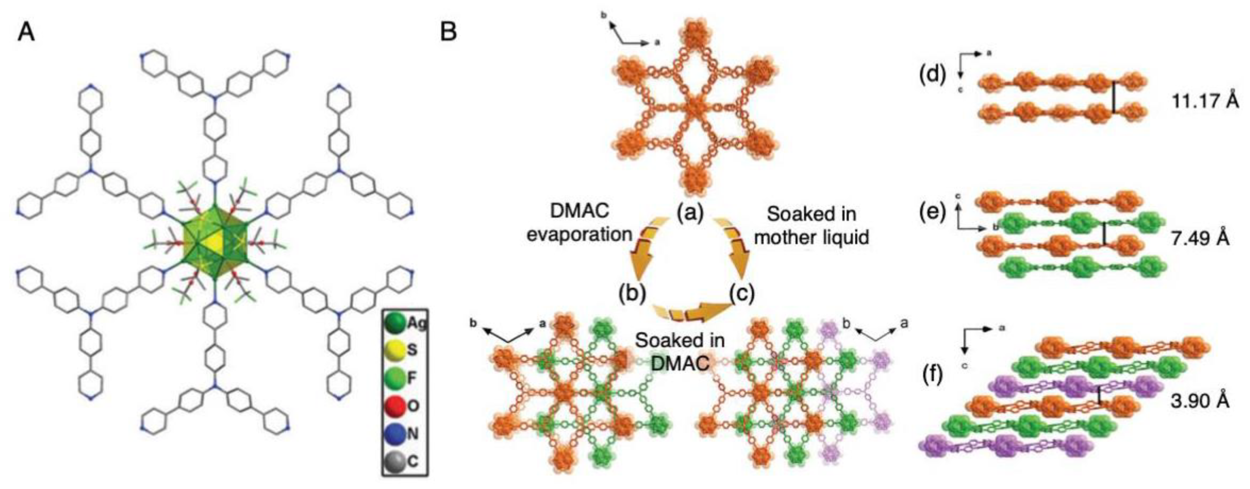
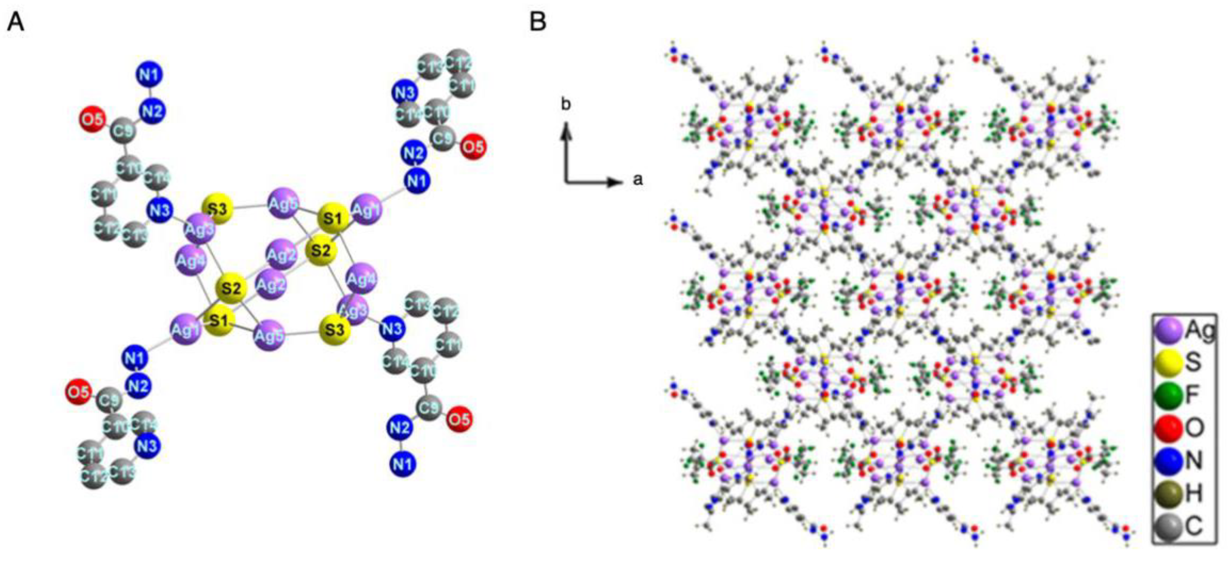
3.2. Introduction of Linker Molecules

As described below, in Section 4.3, in 2017, Zang et al. [168] reported the formation of a 3D CS in which Ag12(S-tBu)8(CF3COO)4 NCs were linked by bpy. This was a pioneering study on the formation of an MOF, using Ag NCs as nodes, and has greatly influenced subsequent studies. In 2018, they synthesized a 2D CS consisting of Ag12 NCs and bpy [169]. The core structure of the node was changed (isomerized) by dissolving an Ag12(S-tBu)6(CF3COO)6 NC MOF crystal in a mixed solvent consisting of N,N-dimethylethanamide (DMAC) and toluene, which changed the geometrical structure of the entire CS from 3D to 2D (Figure 21A,B). This result indicates that the solvent selection is important in the design of the structure of metal NCs and their CSs. In the 2D CS consisting of newly formed Ag12(S-tBu)6(CF3COO)6 NCs, each Ag12(S-tBu)6(CF3COO)6 NC was linked to six adjacent Ag12(S-tBu)6(CF3COO)6 NCs via linkers to produce a highly symmetric 2D CS (Figure 21C). The layers were separated by 7.23 Å, with weak interactions between them. It was also revealed that the reversible structural transformation between 3D and 2D CSs could be induced by appropriate solvent selection (Figure 21A,B).
Structural deformation of the CSs also induced changes in their electronic structure and PL properties. For example, the 3D CS only showed PL at a single wavelength, regardless of temperature and excitation wavelength, whereas the 2D CS exhibited PL of two colors (blue and red), depending on the excitation wavelength (Figure 21D). To enhance the blue emission of the 2D CS, the researchers introduced bpy-NH2, which itself emits blue light, as a linker, to fabricate a 2D CS containing two types of linkers, bpy and bpy-NH2. The intensity ratio of the red and blue PL signals depended on the mixing ratio of linker molecules. At the optimum linker mixing ratio, the PL intensity ratio of the red and blue peaks depended on temperature. Therefore, this 2D CS containing two types of linkers could be used as a temperature sensor (Figure 21E).
In 2018, the same group also reported the formation of a 2D CS consisting of Ag14(DT-o-C)6 NCs [156]. The 2D CS with Ag14(DT-o-C)6, as a structural unit (Figure 22A), was fabricated by changing the linker structure from that used to form the 1D CS (Section 2.4 and Figure 13) to dipyridin-4-yl-diazene (Scheme 2(9)). The obtained 2D CS possessed a rhombic network structure with Ag14(DT-o-C)6(CH3CN)4 as nodes (Figure 22B).
In 2018, Zang et al. [170] reported the formation of a 2D CS consisting of Ag12(S-tBu)6(CF3COO)6 and tris(4-pyridylphenyl)-amine (TPPA; Scheme 2(10) and Figure 23A). This structure is interesting because the distance between the 2D layers can be changed. In this 2D CS, DMAC used as a solvent existed between layers immediately after the synthesis and the 2D layers overlapped, as shown in Figure 23B(a),(d). When the DMAC was partially removed from this structure, the overlap of the 2D layers changed, as illustrated in Figure 23B(b),(e). Furthermore, when this structure was immersed again in the mother liquor, the structure changed to that depicted in Figure 23B(c),(f). It was also found that the size of the crystal and its emission characteristics changed in accordance with the overlap manner in the 2D CS.
Recently, this group also formed a 2D CS with Ag12(StBu)6(CF3COO)3 NCs as nodes by using 5,10,15,20-tetra(4-pyridyl)porphyrin (TPyP, Scheme 2(11)) as a linker (Figure 24A) [171]. TPyP has a photosensitizing effect. Therefore, the ability of the 2D CS to degrade the toxic substance 2-chloroethyl ethyl sulfide (CEES), also called mustard gas, was studied (Figure 24B). The obtained 2D CS showed higher photocatalytic activity than that of a reported MOF. This high photocatalytic activity was ascribed to the synergistic effect of Ag NCs and TPyP, promoting the production of singlet oxygen, which induced the degradation of CEES (Figure 24B). The 2D CS maintained its crystallinity after the photocatalytic reaction and was able to be used repeatedly. The authors pointed out that photocatalytic activity could be further increased by selecting appropriate Ag NCs and organic molecular linkers.
Two other types of 2D CSs were also reported in 2019. In their paper on 1D CS formation (Figure 15 and Section 2.4), Bakr et al. [158] also reported that a 2D CS with Ag14Cl(S-tBu)8(CF3COO)5(DMF) as nodes was formed by changing the concentration of bpy during synthesis (Figure 25A). This Ag14Cl core contained Cl at its center as an anion template. Compared with the Ag15Cl(S-tBu)8(CF3COO)5.67(NO3)0.33(DMF)2 node of the 1D CS, the node of the 2D CS (Ag14Cl(S-tBu)8(CF3COO)5(DMF)) had one less Ag atom. However, the frameworks of these NCs were similar to each other (Figure 25B). The 2D CS showed higher thermal stability than those of individual Ag NCs and the 1D CS (Figure 15D). Unlike individual Ag NCs and the 1D CS, the 2D CS emitted green light with a strong intensity, even at room temperature (Figure 25C). Based on the results of a DFT calculation, it was interpreted that the enhancement of PL intensity was caused by a linker-to-cluster charge transfer excitation. In addition, Gao et al. [159] recently formed a 2D CS (Figure 26) with Ag10(CF3COO)4(S-tBu)6(CH3CN)4 nodes, using 3-pyridine carboxylic hydrazide (m-iah, Scheme 2(12)) as a linker, which is the meta equivalent of p-iah and o-iah used to form 1D CSs (Figure 16).
Thus, 2D CS formation by using a linker leads to the assembly of a structure with high stability and quantum yield (QY). However, 2D CS formation decreases the solubility of NCs, which limits their processability and device applicability. Therefore, Zang et al. [172] recently established a method to polymerize 2D CS to overcome this problem and provide materials suitable for practical use (Figure 27A). In this study, Ag12(S-tBu)6(CF3COO)6 NCs reported in their previous work (Figure 21) [168] were used as nodes. Moreover, 1,4-bis (pyrid-4-yl)benzenamine (bpz-NH2, Scheme 2(13)) was used as the linker. The amino group of the bpz-NH2 linker played an important role in polymerization. First, 2D CS crystals consisting of Ag12(S-tBu)6(CF3COO)6 and bpz-NH2 were fabricated (Figure 27B). The crystal size was limited to about 200–300 nm by quenching the reaction within 1 min. A 2D CS film was obtained by reacting the crystals with methacrylic anhydride (MA). MA bound to the amino group of bpz-NH2 (Figure 27C) and was then polymerized with acrylate monomers butyl methacrylate (BMA) and triethylene glycol dimethacrylate (TEGDMA), as shown in Figure 27D.
The resulting membrane exhibited PL with a QY of 14.8%, which was higher than that of the unpolymerized 2D CS crystals (Figure 28A(a)). The increased PL intensity was ascribed to the polymerization strengthening the structure of the 2D CS, which suppressed molecular vibrations and thus nonradiative decay. The membrane was stable in water regardless of pH (Figure 28A(b)). The researchers also attempted to use the membrane to sense the harmful substance nitrobenzene in solution. The results revealed that the membrane was able to detect nitrobenzene with a sensitivity of 3.19 ppb (Figure 28B). This membrane also displayed high reusability (Figure 28C). These results indicate that polymerizing 2D CSs is an effective approach to obtain Ag NCs suitable for applications.

4. Three-Dimensional Structures

Ag NCs are often used as nodes in 3D CSs. Because 3D CSs generally possess stronger frameworks than those of 2D CSs, the formation of 3D CSs is effective to enhance the stability of Ag NCs and thereby improve their physical properties. In 3D CS formation, the principles of NC assembly are similar to those in 1D and 2D CS formation, although the ligands used are often different. In Section 4.1, Section 4.2 and Section 4.3, we focus on the assembly of 3D CSs via the formation of Ag−O, Ag−S, or Ag−Cl bonds (Figure 2B), control of counterions (Figure 2C), and the introduction of linker molecules (Figure 2D), respectively. The metal NCs, connection modes, linker molecules, year reported, and reference numbers for these studies are summarized in Table 3. Several of the ligands used in 3D CSs are shown in Scheme 1. The organic molecules used as linkers are illustrated in Scheme 2.

4.1. Connection via Ag−O, Ag−S, or Ag−Cl Bonds

In 2017, Mak et al. [148] formed a 3D CS consisting of Ag14(S-iPr)6(CF3COO)11(H2O)3(CH3OH) NCs (Figure 29A). The NCs were connected via O−Ag−O bonds formed between CF3COO and Ag ions (Figure 29B,C). Each Ag NC was connected to six other NCs, thereby forming a distorted octahedral-like coordination structure. It was speculated that this 3D CS formed by the assembly of NCs after NC generation.
In 2019, Sun and colleagues also produced a 3D CS, and theirs consisted of Ag44(Mo6O19)(S-Et)24(SCl4)3 NCs (Figure 30A) containing a POM as an anion template (Figure 30B); these NCs were reported in their paper on 1D CS (Figure 9) and 2D CS (Figure 19) formation [149]. In this 3D CS, Mo6O192− was used as an anion template, which was different from the case of the 1D and 2D CSs, in which the POM V10O286− was located in the center of the cluster. This was the first report in which Mo6O192− was used as an anion template of Ag NCs. Mo6O192− has octahedral symmetry, and thereby the outer Ag44(S-Et)24 layer also displayed high symmetry (Figure 30C). The Ag44 shell had six quadrangles and 24 pentagonal faces. Ag at the vertices of these six quadrangles was connected with one S atom and four Cl atoms, leading to the formation of a 3D CS consisting of Ag44(Mo6O19)(S-Et)24(SCl4)3 (Figure 30D). The S and Cl atoms used in the connections were generated by the decomposition of S-Et and CH2Cl2 during the CS synthesis.
The 3D CS in which Ag NCs are linked by dithiocarb, reported in 2019 by Gao et al. [173], should also be included in this category. The researchers first synthesized an Ag11S(C5NS2H10)9 precursor (C5NS2H10 = diethyldithiocarbamate, Scheme 1(20)) [174]. The obtained precursor was reacted under high pressure, in an autoclave, to form a 3D CS with Ag17(C5NS2H10)14 as a repeating unit. This structure consists of Ag9 NCs bound to twelve C5NS2H10 (Figure 31A) and Ag5 NCs containing six C5NS2H10 (Figure 31B). The 3D CS (Figure 31C) was formed by the sharing of S between the two types of NCs. In these structures, the Ag9 NCs were the nodes for three-point bridges and the Ag5 NCs were the nodes for four-point bridges.

4.2. Control of Counterions

Very recently, Zhu’s group synthesized two types of 3D CSs in which [Au1Ag22(S-Adm)12]3+ NCs (S-Adm = 1-adamantanethiolate, Scheme 1(21)) were connected in three dimensions via hexafluoroantimonate ions (SbF6) [175]. The [Au1Ag22(S-Adm)12]3+ node had a geometric structure in which an icosahedral Au1Ag12 alloy core (Figure 32A(a)) was surrounded by an oligomer with a chemical composition of Ag10(S-Adm)12 (Figure 32A(b),(c)). The [Au1Ag22(S-Adm)12]3+ NCs formed as a pair of optical isomers, depending on the winding method of the oligomer (Figure 32A(b),(c)). In the first 3D CS, [Au1Ag22(S-Adm)12](SbF6)2Cl was a structural unit, and two SbF6 were connected to [Au1Ag22(S-Adm)12]3+ via an Ag−F−Ag bond, to form the 3D CS (Figure 32A(d),(e)). This 3D CS possessed a diamondlike structure (Figure 32A(f)) consisting of interpenetrating clockwise and counterclockwise optical isomers (Figure 32A(g)), which led to a small pore diameter of 6.2 Å (Figure 32A(h)). In the second 3D CS, [Au1Ag22(S-Adm)12](SbF6)3 was a structural unit, and the 3D CS was formed by connecting [Au1Ag22(S-Adm)12]3+ to three SbF6 via Ag−F−Ag bonds (Figure 32B(a)–(c)). This structure only contained clockwise or counterclockwise optical isomers (Figure 32B(d)). As a result, this 3D CS had a larger pore diameter (15 Å, Figure 32B(e)) than that of the first 3D CS (6.2 Å, Figure 32A).
Study of the physical and chemical properties of the 3D CSs revealed that both exhibited red PL in the presence of polar solvents such as CH3OH, ethanol, and water, which disappeared when the solvent was evaporated (Figure 33A). This behavior indicates that the obtained 3D CSs can function as sensors for polar solvents. The 3D CS composed of only the right- or left-handed enantiomer exhibited circularly polarized luminescence (CPL) (Figure 33B).

4.3. Introduction of Linker Molecules

The formation of 3D CSs by using linker molecules is a technique often used to fabricate molecular assemblies and MOFs. When a 3D CS composed of metal NCs is formed by such a method, in addition to increasing the stability of the NCs, it is also expected to adsorb gas molecules within its pores and behave as a catalyst with high selectivity because of the narrow pores. Furthermore, because the metal NCs, which are used as nodes, have more diversity in terms of coordination direction than that of metal ions, metal NC-based MOFs may have different connection modes from those of normal MOFs formed by using metal ions as nodes, and thereby they construct novel framework structures. Thus, metal NC-based MOFs possess not only the characteristics of individual metal NCs and MOFs, but also the possibility to produce new functions through synergistic effects.
Zang’s group have been energetically researching 3D CSs with linkers, as well as the cases of 1D and 2D CSs. First, in 2017, Zang et al. [168] formed an Ag12 NC-based MOF (Ag12(S-tBu)8(CF3COO)4(bpy)4) in which Ag12(S-tBu)8(CF3COO)4 was bridged by bpy (Figure 34A). The obtained Ag12 NC-based MOF possessed a bilayer structure (Figure 34B). The formation of such a 3D CS markedly improved the stability of the Ag12 NCs. For example, a crystal of the individual Ag12(S-tBu)6(CF3COO)6(CH3CN)6 NCs discolored in just 30 min when left in the atmosphere. In contrast, the Ag12 NC-based MOF showed almost no change in crystallinity, even when left in the air for one year (Figure 34C). The 3D CS also showed high stability during long-term gas adsorption and irradiation with visible light for several hours.
The formation of the 3D CS greatly changed the PL properties of the NCs. The individual Ag12 NCs exhibited red PL with low QY. Conversely, the Ag12 NC-based MOF exhibited green PL under vacuum, which was quenched by O2 in the atmosphere (Figure 35A). The PL emission wavelength of the 3D CS under vacuum was independent of temperature and excitation wavelength, and its QY was 60 times higher than that of individual Ag12 NCs. The authors ascribed this high QY to the efficient suppression of nonradiative decay in the 3D CS. Moreover, the fact that the PL of the 3D CS is quenched by O2 means that it is highly sensitive to O2. The 3D CS showed a fast response to O2 in experiments in which the atmosphere was repeatedly switched between air and N2. No such O2 response was observed for the individual Ag12 NCs. Based on these results, they suggested that the Ag12 NC-based MOF can be applied as an O2 sensor. In addition, the Ag12 NC-based MOF was able to adsorb volatile organic compounds (VOCs) in its pores. The VOC-containing Ag12 NC-based MOF exhibited different PL colors, depending on the kind of VOC (Figure 35B). This indicates that the Ag12 NC-based MOF displays solvatochromism and therefore can be used for VOC detection.
In a paper on Ag14(DT-o-C)6 NCs published in 2018 (Figure 13 and Figure 22), the same group reported that a 3D CS containing Ag14(DT-o-C)6 NCs formed when bpy was used as a linker (Figure 36A) [156]. The Ag14 NC nodes in the 3D CS had a face-centered cubic structure like that of other Ag14 NCs. This 3D CS was formed by connecting the eight vertices of each Ag14 NC with bpy linker molecules. However, this 3D CS was not stable after solvent evaporation, similar to the case of the corresponding 1D CS (Figure 13) and 2D CS (Figure 22) [156]. Therefore, they synthesized a 3D CS with an interpenetrating framework by using 1,4-bis(4-pyridyl)benzene (Scheme 2(14)) as a linker, in order to decrease the pore size and form a 3D CS with a strong framework (Figure 36B). The obtained 3D CS showed high thermal stability, remaining intact up to 220 °C (Figure 36C), and possessed pores with a diameter of about 1.12 nm (Figure 36D). This 3D CS showed optical absorption over a wide wavelength range and thermochromism (Figure 36E).
Zang et al. [176] have also produced several other functional Ag NC-based MOFs. For example, in 2018, they reported the synthesis of a flexible Ag NC-based MOF. This structure consisted of 2D layers of Ag10(S-tBu)6(CF3COO)2(PhPO3H)2 NCs linked via bpy, which were stacked through hydrogen bond (O-H···O) and C-H···O interactions, to form the 3D CS (Figure 37A,B). The 2D CS layers were thus linked by weak interactions, which facilitated the sliding of the layers, allowing the 3D CS to undergo structural deformation in response to guest organic molecules (Figure 37C). This Ag10 NC-based MOF exhibited green PL in air. Upon inclusion of guest organic molecules, it exhibited PL with an emission color depending on the guest organic molecule (Figure 37D). As such, this Ag10 NC-based MOF has potential as a sensor for distinguishing VOCs by its PL color. In 2019, they also formed a 3D CS consisting of Ag12(S-tBu)6(CF3COO)6 NC nodes and 2,5-bis(4-cyanophenyl)-1,4-bis(4-(pyridine-4-yl)-phenyl)-1,4-dihydropyrrolo[3,2-b]pyrrole (CPPP, Scheme 2(15)) as a linker (Figure 38A) [177]. This was the first report in which a nitrile group (-CN) was used to link Ag NCs. The obtained 3D CS exhibited PL with a higher QY (61%) than that of CPPP in solution and solid states because the aggregation-induced quenching of CPPP was suppressed in the 3D CS (Figure 38B).
In the above 3D CSs, the nodes consisted of only one kind of Ag NCs. Tang et al. [178] synthesized an Ag NC-based MOF that had two types of Ag NCs as nodes. This Ag NC-based MOF was composed of 1,1,2,2-tetrakis(4-(pyridin-4-yl)phenyl)-ethene (tppe, Scheme 2(16)), Ag12(S-tBu)6(CF3COO)6, and Ag8(S-tBu)4(CF3COO)4 (Figure 39). In the 3D CS, one Ag12(S-tBu)6(CF3COO)6 NC and three Ag8(S-tBu)4(CF3COO)4 NCs were bound to the four N atoms of tppe. The estimated pore volume of this Ag NC-based MOF was 40.9%. DMAC, which was used as a solvent in the synthesis, was present in the pores of the 3D CS immediately after synthesis (Figure 40A). When the obtained 3D CS was exposed to the atmosphere, DMAC was removed, while maintaining the framework of the 3D CS. The Ag NC-based MOF thus obtained exhibited PL in the visible region because tppe is a light-emitting molecule. The PL wavelength of the 3D CS depended on the presence or absence of DMAC in its pores (Figure 40B). When DMAC was present in the pores of the framework, intramolecular rotation of tppe was suppressed, which changed the excited-state dynamics of the 3D CS. The change in the emission behavior of the Ag NC-based MOF induced by DMAC was ascribed to this change of its excited-state characteristics (Figure 40C).
Wang and colleagues reported the formation of a 3D CS, using metal NCs as linkers, before the use of metal NCs as nodes was developed [179]. In 2014, they succeeded in forming an NbO-type MOF by using Ag ions as nodes and [C(Au-mdppz)6](BF4)2] (mdppz = 2-(3-methylpyrazinyl)diphenylphosphine, Scheme 2(17)) NCs as linkers (Figure 41). [C(Au-mdppz)6](BF4)2 has a framework with C in the center (Figure 41A) and is luminescent. The 3D CS was formed by the outer N atom of mdppz (Scheme 2(17)) binding to an Ag ion (Figure 41B,C). The obtained 3D CS consisted of two interpenetrating frameworks (Figure 41D,E) with a 1D channel in the c-axis direction (Figure 41C). Because a luminescent NC was used as the linker, the obtained MOF also showed green PL. The 3D CS displayed a PL QY of 25.6%, which was much higher than that of the luminescent NCs (1.5%). This increase of QY was caused by the strengthening of the framework of the linker NCs upon MOF formation and the excited-state perturbation induced by the coordination of Ag ions.

5. Summary

In this review, representative studies on the formation of 1D, 2D, and 3D CSs in which metal NCs were self-organized and regularly linked were summarized. From this summary, the following points became clear.
(1)
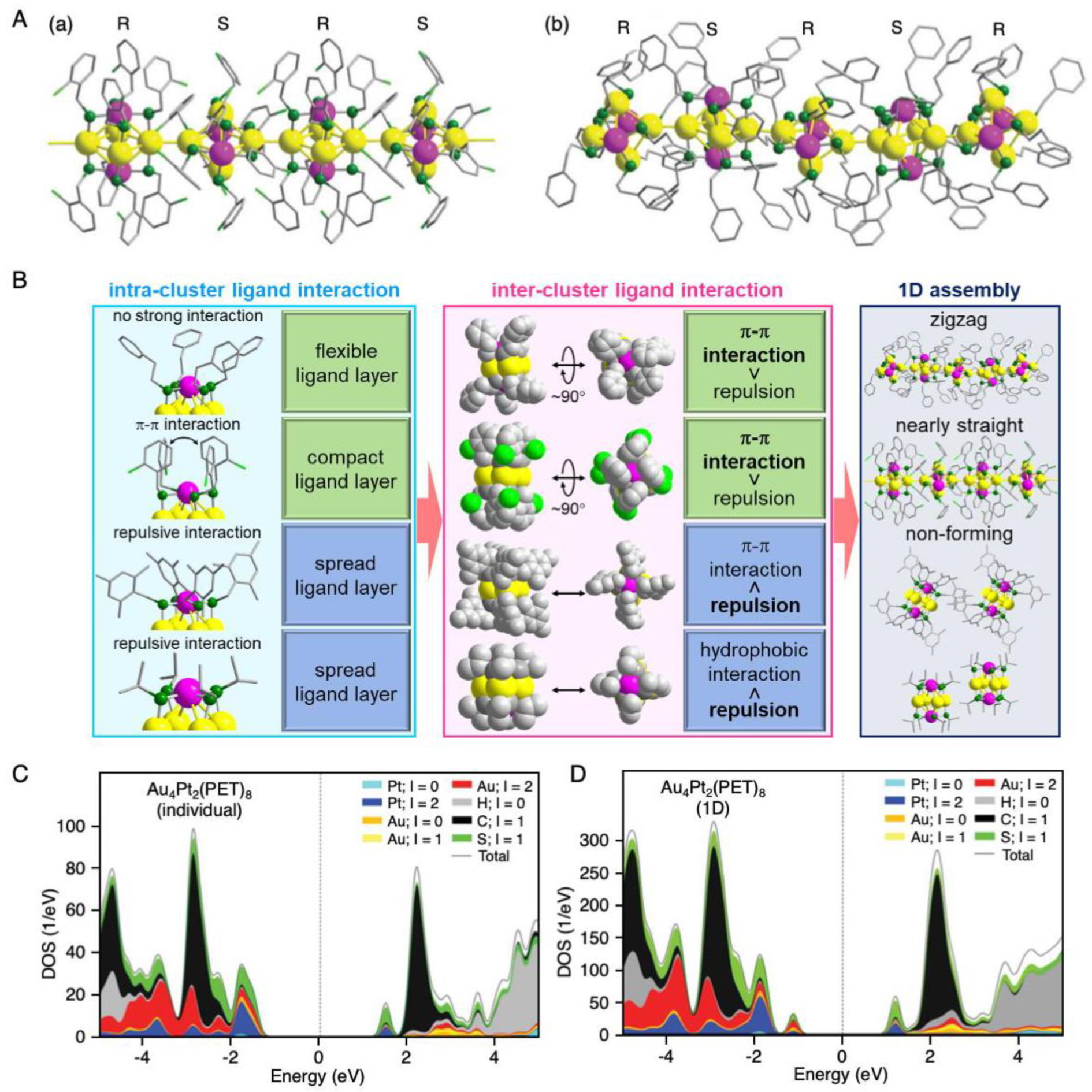
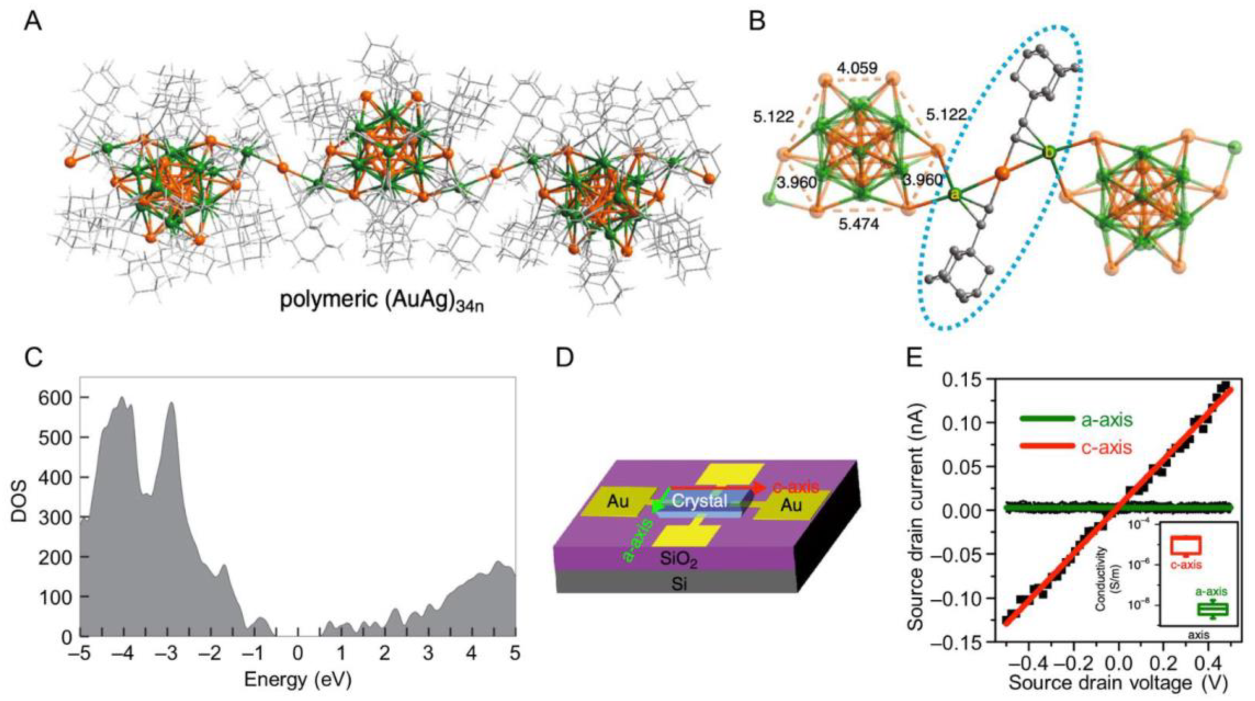
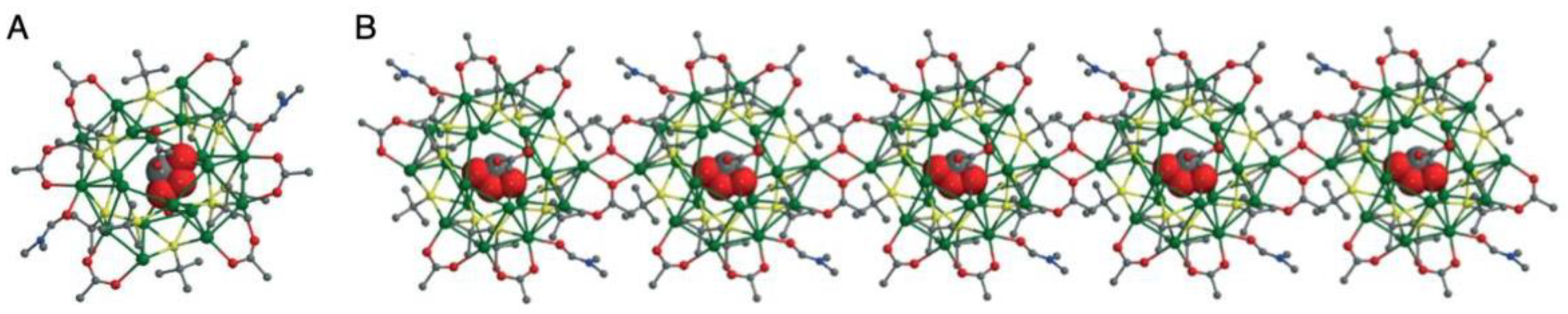
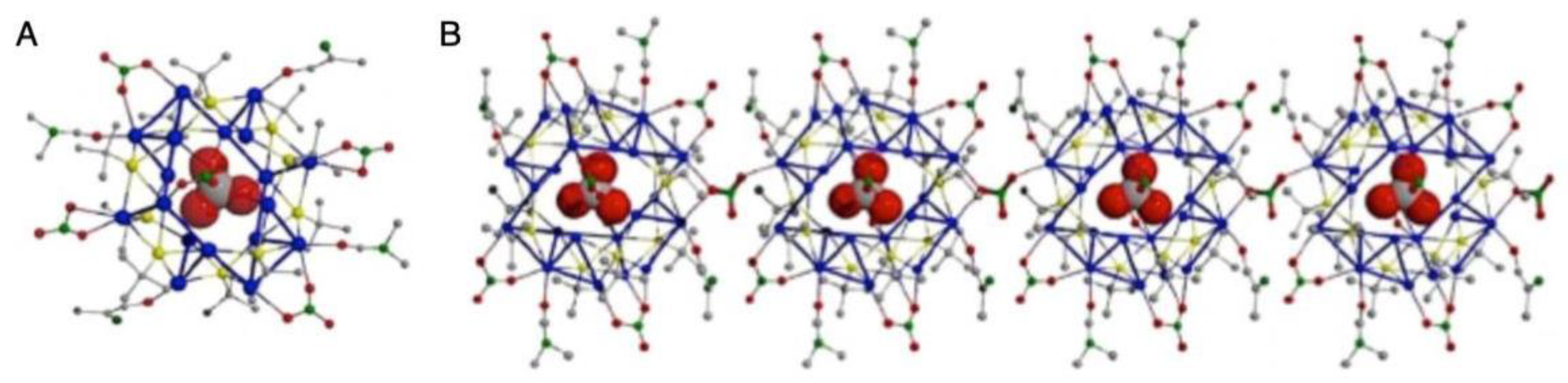
Methods. The methods to connect metal NCs that have been reported to date can be roughly divided into the following five categories: (i) direct connection by formation of metal−metal bonds (Figure 2A); (ii) connection by Ag−O, Ag−S, or Ag−Cl bond formation (Figure 2B); (iii) connection by counterions (Figure 2C); (iv) connection by linker molecules (Figure 2D); and (v) connection by inter-ligand interactions (Figure 2E; not introduced in this review).
(2)
Diversity. Among CSs produced by the above methods, there are many examples of the formation of 1D, 2D, and 3D CSs through the use of methods (ii) and (iv). An important point when constructing CSs by these methods is the design of the ligand of the NCs and linker, respectively. It is presumed that the control of these species is relatively easy, which has led to the wider utilization of methods (ii) and (iv) than of the other methods. In particular, for method (iv), existing knowledge obtained in the study of normal MOFs can be considered.
(3)
Metal element. To directly connect metal NCs, it is effective to use Au as a main element because it forms strong aurophilic interactions (intermetal interactions). In the connections involving metal−O or metal−Cl bonds, it is effective to use Ag as a main element because it readily bonds with O or Cl. Moreover, in the connections using bpy as a linker, Ag is attractive as the main element because of the high affinity of N and Ag.
(4)
Stability. The formation of a CS generally improves the thermal stability of the component metal NCs regardless of the connection mode.
(5)
Electronic structure. The formation of a CS often causes the band gap of the NC to narrow. This means that CS formation allows the use of a broader wavelength range of light, opening up the possibility of visible-light-driven photocatalysis by using CSs.
(6)
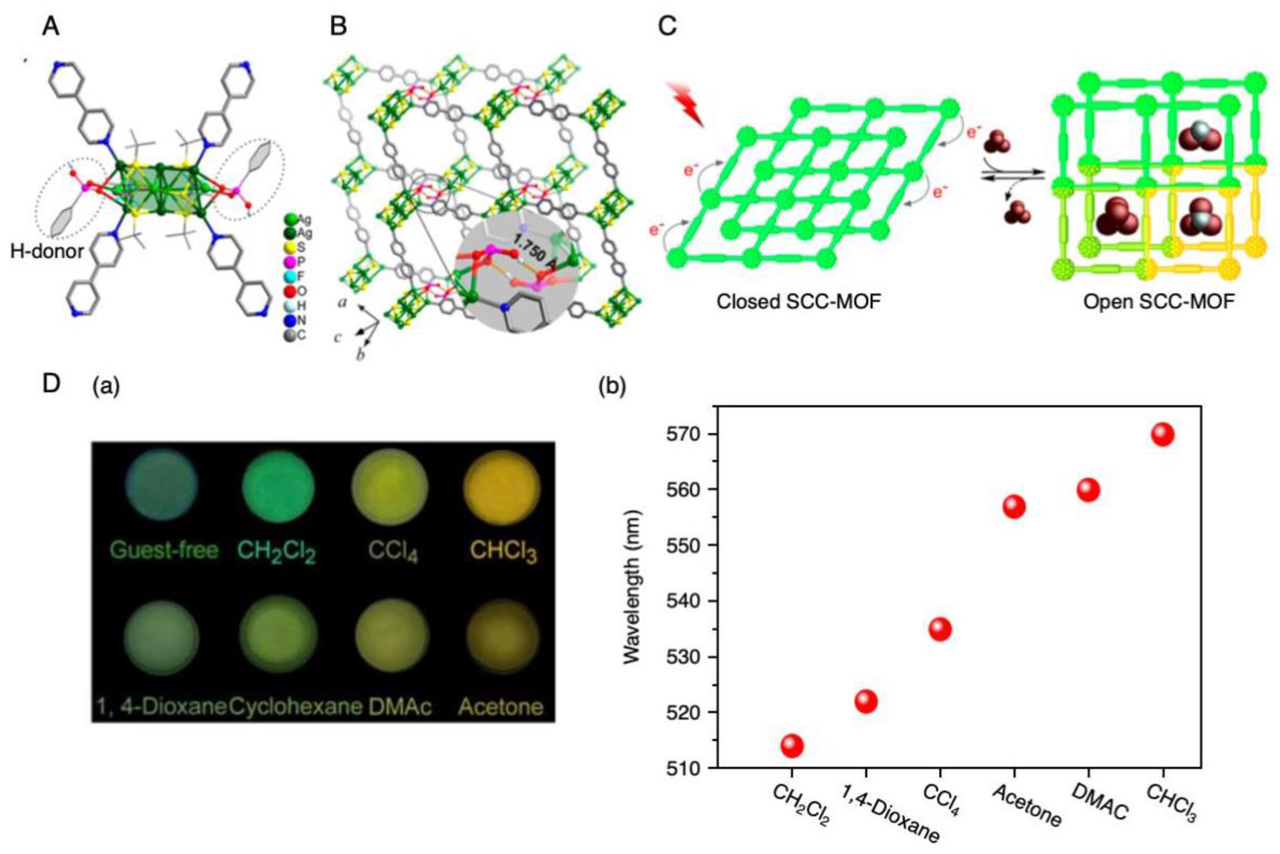
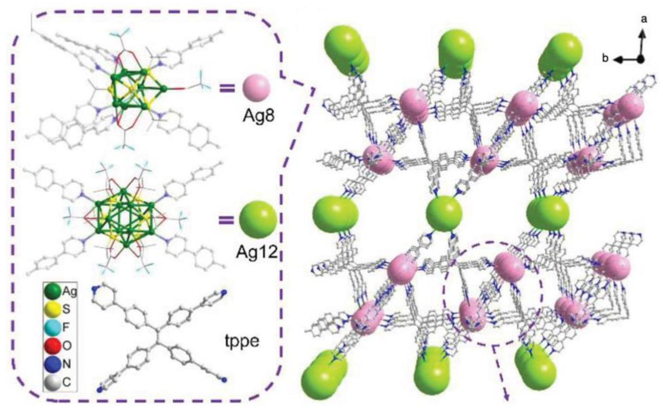
PL properties. For 2D and 3D CS using linkers, CS formation often leads to an increase in PL emission intensity. When metal NCs are the PL source, there are many cases in which dual emission peaks appear upon connection with a linker. In addition, the PL color of a CS often changes depending on the kind of VOC trapped in its pores.
(7)
Electrical conduction. The electron conductivity of CSs changes dramatically depending on the distance between each metal NC and the mode of connection; 1D CS formed by the direct connection via metal−metal bond shows the higher conductivity than 1D CS connected through counter ion.
(8)
Possible applications. The reported CSs have potential applications in fields such as electronic devices, luminescent devices, gas and temperature sensing, and photocatalysis.
This review allowed us to obtain a common understanding of the CSs reported to date and their functions. We hope that the knowledge thus clarified will lead to clear design guidelines for developing new CSs with desired functions in the future.

6. Outlook

It is expected that the following studies will be conducted in the future, leading to new CSs.
(1)
Use of other metal elements. At present, mostly Au and Ag are used as the metal element in CSs. This is largely related to the high stability of Au and Ag NCs. For Ag NCs, the good connectivity between Ag and linker molecules is also related to this fact. On the other hand, several syntheses of individual copper (Cu) NCs have been reported recently [10,180,181,182,183]. In addition, other metal ions are often used in normal MOFs with metal ions as nodes [153]. CS formation of NCs based on Cu or other metals may also lead to materials with high thermal stability. In the future, it is expected that many elements will be used in CSs, thereby realizing various functions and decreased cost of such materials.
(2)
Use of the alloying effect. At present, there are few examples in which alloy NCs are connected to form CSs [142,143,146]. Mixing different elements leads to NCs with physical/chemical properties and functions that are different from those of monometal NCs. In fact, for individual metal NCs, many cases have been reported in which new physical properties/functions appeared because of mixing/synergistic effects [66,184,185,186,187,188,189,190,191,192,193,194]. The previous studies have established basic techniques for the formation of CSs consisting of Ag NCs. In the future, it is expected that more functional materials will be created by extending such CS formation techniques to Ag-based alloy NCs.
(3)
Connection of reported metal NCs. Ag NC-based MOFs are interesting because they can be synthesized by a one-pot process. However, in CSs formed by such a method, metal NCs that are stable only in the CS are often found as nodes. For individual metal NCs, many NCs have already been synthesized with atomic precision [1,2,3,4,5,6,7,8,9,10,11,12,13,14,15,16,17,18,19,20,21,22,23,24,25,26,27,28,29,30,31,32,33,34,35,36,37,38,39,40,41,42,43,44,45,46,47,48,49,50,51,52,53,54,55,56,57,58,59,60,61,62,63,64,65]. In addition, much information has been obtained on methods to generate novel functions in such NCs, including alloying [66,67,68]. In the future, it is expected that a method to more effectively utilize the reported metal NCs in CSs will be found. To achieve this, it may be necessary to establish new connection methods different from those described in this review (Figure 2).
(4)
Elucidation of electronic conductivity. We believe that 1D CSs may be applied as nanodevices. However, at present, few experiments on the conductivity of 1D CSs have been reported [146,152]. In the future, it is expected that the conductivity of 1D CSs will be measured as a basic physical property. It is anticipated that the accumulation of such information will eventually lead to the production of nanodevices based on 1D CSs of metal NCs.
(5)
Exploration of other possible applications of connected structures. Various applications, such as gas storage, gas separation, gas conversion, and reaction-selective catalysis, have been studied for normal MOFs with metal ions as nodes [117]. It has also been reported that, in the case of self-assembled complexes, a reaction different from that in the case of using an ordinary flask proceeds in the cage structure (i.e., the cage behaves as a nanoflask) [116]. In the future, it is expected that these possibilities will be investigated for metal NC-based MOFs and that their functions will be much higher than those of conventional MOFs and self-assembled complexes.
As mentioned in Section 1, the advance of bottom-up technology is essential for the further development of nanotechnology in the future. In previous research, multiple techniques to generate metal atoms on the molar scale in a solution and to self-organize them to form nanomaterials with the same number of constituent atoms and the same number of molecules have been studied; that is, precise synthesis techniques of metal NCs have been developed. However, to apply these metal NCs as devices and next-generation materials, developing techniques to assemble metal NCs to a size that is easy to handle is necessary (Figure 1). We hope that technologies that allow the self-organization of regularly arranged CSs composed of metal NCs will be further developed in the future. Ultimately, such nanotechnology is expected to enable resource conservation, energy conservation, decreased waste and environmental load, and the better use of time by human society.

Author Contributions

Y.N. constructed the structure of this review; T.K., S.O., and S.K. wrote Section 1, Section 5, and Section 6 and compiled figures and tables; A.E. wrote Section 3 and Section 4; H.H. wrote Section 2; Y.N. and S.H. revised the entire draft before submission. All authors have read and agreed to the published version of the manuscript.

Funding

This work was supported by the Japan Society for the Promotion of Science (JSPS) KAKENHI (grant numbers JP16H04099, 16K21402, 20H02698, and 20H02552), Scientific Research on Innovative Areas “Coordination Asymmetry” (grant numbers 17H05385 and 19H04595), and Scientific Research on Innovative Areas “Innovations for Light-Energy Conversion” (grant numbers 18H05178 and 20H05115). Funding from the Asahi Glass Foundation, TEPCO Memorial Foundation Research Grant (Basic Research), and Kato Foundation for Promotion of Science (grant number KJ-2904) is also gratefully acknowledged.

Conflicts of Interest

There are no conflicts to declare.

References

  1. Pradeep, T. Nano: The Essentials, 3rd ed.; Tata McGraw-Hill Education: New Delhi, India, 2008. [Google Scholar]
  2. Jin, R.; Zeng, C.; Zhou, M.; Chen, Y. Atomically Precise Colloidal Metal Nanoclusters and Nanoparticles: Fundamentals and Opportunities. Chem. Rev. 2016, 116, 10346–10413. [Google Scholar] [CrossRef] [PubMed]
  3. Nasaruddin, R.R.; Chen, T.; Yan, N.; Xie, J. Roles of Thiolate Ligands in the Synthesis, Properties and Catalytic Application of Gold Nanoclusters. Coord. Chem. Rev. 2018, 368, 60–79. [Google Scholar] [CrossRef]
  4. Du, Y.; Sheng, H.; Astruc, D.; Zhu, M. Atomically Precise Noble Metal Nanoclusters as Efficient Catalysts: A Bridge between Structure and Properties. Chem. Rev. 2020, 120, 526–622. [Google Scholar] [CrossRef] [PubMed]
  5. Sakthivel, N.A.; Dass, A. Aromatic Thiolate-Protected Series of Gold Nanomolecules and a Contrary Structural Trend in Size Evolution. Acc. Chem. Res. 2018, 51, 1774–1783. [Google Scholar] [CrossRef]
  6. Kawasaki, H.; Kumar, S.; Li, G.; Zeng, C.; Kauffman, D.R.; Yoshimoto, J.; Iwasaki, Y.; Jin, R. Generation of Singlet Oxygen by Photoexcited Au25(SR)18 Clusters. Chem. Mater. 2014, 26, 2777–2788. [Google Scholar] [CrossRef]
  7. Yamamoto, K.; Imaoka, T.; Tanabe, M.; Kambe, T. New Horizon of Nanoparticle and Cluster Catalysis with Dendrimers. Chem. Rev. 2020, 120, 1397–1437. [Google Scholar] [CrossRef]
  8. Whetten, R.L.; Weissker, H.-C.; Pelayo, J.J.; Mullins, S.M.; López-Lozano, X.; Garzón, I.L. Chiral-Icosahedral (I) Symmetry in Ubiquitous Metallic Cluster Compounds (145A,60X): Structure and Bonding Principles. Acc. Chem. Res. 2019, 52, 34–43. [Google Scholar] [CrossRef] [PubMed] [Green Version]
  9. Bakar, M.A.; Sugiuchi, M.; Iwasaki, M.; Shichibu, Y.; Konishi, K. Hydrogen Bonds to Au Atoms in Coordinated Gold Clusters. Nat. Commun. 2017, 8, 576. [Google Scholar] [CrossRef]
  10. Sharma, S.; Chakrahari, K.K.; Saillard, J.-Y.; Liu, C.W. Structurally Precise Dichalcogenolate-Protected Copper and Silver Superatomic Nanoclusters and Their Alloys. Acc. Chem. Res. 2018, 51, 2475–2483. [Google Scholar] [CrossRef]
  11. Brust, M.; Walker, M.; Bethell, D.; Schiffrin, D.J.; Whyman, R. Synthesis of Thiol-derivatised Gold Nanoparticles in a Two-Phase Liquid-Liquid System. J. Chem. Soc. Chem. Commun. 1994, 801–802. [Google Scholar] [CrossRef]
  12. Whetten, R.L.; Khoury, J.T.; Alvarez, M.M.; Murthy, S.; Vezmar, I.; Wang, Z.L.; Stephens, P.W.; Cleveland, C.L.; Luedtke, W.D.; Landman, U. Nanocrystal Gold Molecules. Adv. Mater. 1996, 8, 428–433. [Google Scholar] [CrossRef]
  13. Schaaff, T.G.; Shafigullin, M.N.; Khoury, J.T.; Vezmar, I.; Whetten, R.L.; Cullen, W.G.; First, P.N.; Gutiérrez-Wing, C.; Ascensio, J.; Jose-Yacamán, M.J. Isolation of Smaller Nanocrystal Au Molecules:  Robust Quantum Effects in Optical Spectra. J. Phys. Chem. B 1997, 101, 7885–7891. [Google Scholar] [CrossRef]
  14. Donkers, R.L.; Lee, D.; Murray, R.W. Synthesis and Isolation of the Molecule-Like Cluster Au38(PhCH2CH2S)24. Langmuir 2004, 20, 1945–1952. [Google Scholar] [CrossRef]
  15. Ingram, R.S.; Hostetler, M.J.; Murray, R.W.; Schaaff, T.G.; Khoury, J.T.; Whetten, R.L.; Bigioni, T.P.; Guthrie, D.K.; First, P.N. 28 kDa Alkanethiolate-Protected Au Clusters Give Analogous Solution Electrochemistry and STM Coulomb Staircases. J. Am. Chem. Soc. 1997, 119, 9279–9280. [Google Scholar] [CrossRef]
  16. Schaaff, T.G.; Shafigullin, M.N.; Khoury, J.T.; Vezmar, I.; Whetten, R.L. Properties of a Ubiquitous 29 kDa Au:SR Cluster Compound. J. Phys. Chem. B 2001, 105, 8785–8796. [Google Scholar] [CrossRef]
  17. Murthy, S.; Bigioni, T.P.; Wang, Z.L.; Khoury, J.T.; Whetten, R.L. Liquid-Phase Synthesis of Thiol-Derivatized Silver Nanocrystals. Mater. Lett. 1997, 30, 321–325. [Google Scholar] [CrossRef]
  18. Link, S.; Beeby, A.; FitzGerald, S.; El-Sayed, M.A.; Schaaff, T.G.; Whetten, R.L. Visible to Infrared Luminescence from a 28-Atom Gold Cluster. J. Phys. Chem. B 2002, 106, 3410–3415. [Google Scholar] [CrossRef]
  19. Hostetler, M.J.; Wingate, J.E.; Zhong, C.-J.; Harris, J.E.; Vachet, R.W.; Clark, M.R.; Londono, J.D.; Green, S.J.; Stokes, J.J.; Wignall, G.D.; et al. Alkanethiolate Gold Cluster Molecules with Core Diameters from 1.5 to 5.2 nm:  Core and Monolayer Properties as a Function of Core Size. Langmuir 1998, 14, 17–30. [Google Scholar] [CrossRef]
  20. Hostetler, M.J.; Stokes, J.J.; Murray, R.W. Infrared Spectroscopy of Three-Dimensional Self-Assembled Monolayers: N-Alkanethiolate Monolayers on Gold Cluster Compounds. Langmuir 1996, 12, 3604–3612. [Google Scholar] [CrossRef]
  21. Terrill, R.H.; Postlethwaite, T.A.; Chen, C.-H.; Poon, C.-D.; Terzis, A.; Chen, A.; Hutchison, J.E.; Clark, M.R.; Wignall, G.; Londono, J.D.; et al. Monolayers in Three Dimensions: NMR, SAXS, Thermal, and Electron Hopping Studies of Alkanethiol Stabilized Gold Clusters. J. Am. Chem. Soc. 1995, 117, 12537–12548. [Google Scholar] [CrossRef]
  22. Schaaff, T.G.; Knight, G.; Shafigullin, M.N.; Borkman, R.F.; Whetten, R.L. Isolation and Selected Properties of a 10.4 kDa Gold: Glutathione Cluster Compound. J. Phys. Chem. B 1998, 102, 10643–10646. [Google Scholar] [CrossRef]
  23. Schaaff, T.G.; Whetten, R.L. Giant Gold–Glutathione Cluster Compounds:  Intense Optical Activity in Metal-Based Transitions. J. Phys. Chem. B 2000, 104, 2630–2641. [Google Scholar] [CrossRef]
  24. Alvarez, M.M.; Chen, J.; Plascencia-Villa, G.; Black, D.M.; Griffith, W.P.; Garzón, I.L.; José-Yacamán, M.; Demeler, B.; Whetten, R.L. Hidden Components in Aqueous “Gold-144” Fractionated by PAGE: High-Resolution Orbitrap ESI-MS Identifies the Gold-102 and Higher All-Aromatic Au-pMBA Cluster Compounds. J. Phys. Chem. B 2016, 120, 6430–6438. [Google Scholar] [CrossRef]
  25. Plascencia-Villa, G.; Demeler, B.; Whetten, R.L.; Griffith, W.P.; Alvarez, M.; Black, D.M.; José-Yacamán, M. Analytical Characterization of Size-Dependent Properties of Larger Aqueous Gold Nanoclusters. J. Phys. Chem. C 2016, 120, 8950–8958. [Google Scholar] [CrossRef]
  26. Bootharaju, M.S.; Burlakov, V.M.; Besong, T.M.D.; Joshi, C.P.; AbdulHalim, L.G.; Black, D.M.; Whetten, R.L.; Goriely, A.; Bakr, O.M. Reversible Size Control of Silver Nanoclusters via Ligand-Exchange. Chem. Mater. 2015, 27, 4289–4297. [Google Scholar] [CrossRef] [Green Version]
  27. Heaven, M.W.; Dass, A.; White, P.S.; Holt, K.M.; Murray, R.W. Crystal Structure of the Gold Nanoparticle [N(C8H17)4] [Au25(SCH2CH2Ph)18]. J. Am. Chem. Soc. 2008, 130, 3754–3755. [Google Scholar] [CrossRef] [PubMed]
  28. Negishi, Y.; Sakamoto, C.; Ohyama, T.; Tsukuda, T. Synthesis and the Origin of the Stability of Thiolate-Protected Au130 and Au187 Clusters. J. Phys. Chem. Lett. 2012, 3, 1624–1628. [Google Scholar] [CrossRef]
  29. Negishi, Y.; Nakazaki, T.; Malola, S.; Takano, S.; Niihori, Y.; Kurashige, W.; Yamazoe, S.; Tsukuda, T.; Häkkinen, H. A Critical Size for Emergence of Nonbulk Electronic and Geometric Structures in Dodecanethiolate-Protected Au Clusters. J. Am. Chem. Soc. 2015, 137, 1206–1212. [Google Scholar] [CrossRef]
  30. Negishi, Y.; Kurashige, W.; Niihori, Y.; Iwasa, T.; Nobusada, K. Isolation, Structure, and Stability of a Dodecanethiolate-Protected Pd1Au24 Cluster. Phys. Chem. Chem. Phys. 2010, 12, 6219–6225. [Google Scholar] [CrossRef]
  31. Negishi, Y.; Iwai, T.; Ide, M. Continuous Modulation of Electronic Structure of Stable Thiolate-Protected Au25 Cluster by Ag Doping. Chem. Commun. 2010, 46, 4713–4715. [Google Scholar] [CrossRef]
  32. Negishi, Y.; Kurashige, W.; Kobayashi, Y.; Yamazoe, S.; Kojima, N.; Seto, M.; Tsukuda, T. Formation of a Pd@Au12 Superatomic Core in Au24Pd1(SC12H25)18 Probed by 197Au Mössbauer and Pd K-Edge EXAFS Spectroscopy. J. Phys. Chem. Lett. 2013, 4, 3579–3583. [Google Scholar] [CrossRef]
  33. Negishi, Y.; Munakata, K.; Ohgake, W.; Nobusada, K. Effect of Copper Doping on Electronic Structure, Geometric Structure, and Stability of Thiolate-Protected Au25 Nanoclusters. J. Phys. Chem. Lett. 2012, 3, 2209–2214. [Google Scholar] [CrossRef] [PubMed]
  34. Niihori, Y.; Matsuzaki, M.; Pradeep, T.; Negishi, Y. Separation of Precise Compositions of Noble Metal Clusters Protected with Mixed Ligands. J. Am. Chem. Soc. 2013, 135, 4946–4949. [Google Scholar] [CrossRef] [PubMed]
  35. Niihori, Y.; Matsuzaki, M.; Uchida, C.; Negishi, Y. Advanced Use of High-Performance Liquid Chromatography for Synthesis of Controlled Metal Clusters. Nanoscale 2014, 6, 7889–7896. [Google Scholar] [CrossRef]
  36. Niihori, Y.; Kikuchi, Y.; Kato, A.; Matsuzaki, M.; Negishi, Y. Understanding Ligand Exchange Reactions on Thiolate-Protected Gold Clusters by Probing Isomer Distributions Using Reversed-Phase High-Performance Liquid Chromatography. ACS Nano 2015, 9, 9347–9356. [Google Scholar] [CrossRef]
  37. Niihori, Y.; Eguro, M.; Kato, A.; Sharma, S.; Kumar, B.; Kurashige, W.; Nobusada, K.; Negishi, Y. Improvements in the Ligand-Exchange Reactivity of Phenylethanethiolate-Protected Au25 Nanocluster by Ag or Cu Incorporation. J. Phys. Chem. C 2016, 120, 14301–14309. [Google Scholar] [CrossRef]
  38. Niihori, Y.; Koyama, Y.; Watanabe, S.; Hashimoto, S.; Hossain, S.; Nair, L.V.; Kumar, B.; Kurashige, W.; Negishi, Y. Atomic and Isomeric Separation of Thiolate-Protected Alloy Clusters. J. Phys. Chem. Lett. 2018, 9, 4930–4934. [Google Scholar] [CrossRef] [PubMed]
  39. Niihori, Y.; Hashimoto, S.; Koyama, Y.; Hossain, S.; Kurashige, W.; Negishi, Y. Dynamic Behavior of Thiolate-Protected Gold–Silver 38-Atom Alloy Clusters in Solution. J. Phys. Chem. C 2019, 123, 13324–13329. [Google Scholar] [CrossRef]
  40. Niihori, Y.; Kikuchi, Y.; Shima, D.; Uchida, C.; Sharma, S.; Hossain, S.; Kurashige, W.; Negishi, Y. Separation of Glutathionate-Protected Gold Clusters by Reversed-Phase Ion-Pair High-Performance Liquid Chromatography. Ind. Eng. Chem. Res. 2017, 56, 1029–1035. [Google Scholar] [CrossRef]
  41. Niihori, Y.; Shima, D.; Yoshida, K.; Hamada, K.; Nair, L.V.; Hossain, S.; Kurashige, W.; Negishi, Y. High-Performance Liquid Chromatography Mass Spectrometry of Gold and Alloy Clusters Protected by Hydrophilic Thiolates. Nanoscale 2018, 10, 1641–1649. [Google Scholar] [CrossRef]
  42. Murayama, H.; Narushima, T.; Negishi, Y.; Tsukuda, T. Structures and Stabilities of Alkanethiolate Monolayers on Palladium Clusters As Studied by Gel Permeation Chromatography. J. Phys. Chem. B 2004, 108, 3496–3503. [Google Scholar] [CrossRef]
  43. Tsunoyama, H.; Negishi, Y.; Tsukuda, T. Chromatographic Isolation of “Missing” Au55 Clusters Protected by Alkanethiolates. J. Am. Chem. Soc. 2006, 128, 6036–6037. [Google Scholar] [CrossRef] [PubMed]
  44. Negishi, Y.; Arai, R.; Niihori, Y.; Tsukuda, T. Isolation and Structural Characterization of Magic Silver Clusters Protected by 4-(tert-butyl) benzyl mercaptan. Chem. Commun. 2011, 47, 5693–5695. [Google Scholar] [CrossRef] [PubMed] [Green Version]
  45. Kurashige, W.; Yamazoe, S.; Yamaguchi, M.; Nishido, K.; Nobusada, K.; Tsukuda, T.; Negishi, Y. Au25 Clusters Containing Unoxidized Tellurolates in the Ligand Shell. J. Phys. Chem. Lett. 2014, 5, 2072–2076. [Google Scholar] [CrossRef]
  46. Negishi, Y.; Takasugi, Y.; Sato, S.; Yao, H.; Kimura, K.; Tsukuda, T. Structures, Stabilities and Physicochemical Properties of Organometallic Hybrid Clusters. J. Am. Chem. Soc. 2004, 126, 6518–6519. [Google Scholar] [CrossRef]
  47. Shichibu, Y.; Negishi, Y.; Tsunoyama, H.; Kanehara, M.; Teranishi, T.; Tsukuda, T. Extremely High Stability of Glutathionate-Protected Au25 Clusters Against Core Etching. Small 2007, 3, 835–839. [Google Scholar] [CrossRef]
  48. Shichibu, Y.; Negishi, Y.; Tsukuda, T.; Teranishi, T. Large-Scale Synthesis of Thiolated Au25 Clusters via Ligand Exchange Reactions of Phosphine-Stabilized Au11 Clusters. J. Am. Chem. Soc. 2005, 127, 13464–13465. [Google Scholar] [CrossRef]
  49. Ikeda, K.; Kobayashi, Y.; Negishi, Y.; Seto, M.; Iwasa, T.; Nobusada, K.; Tsukuda, T.; Kojima, N. Thiolate-Induced Structural Reconstruction of Gold Clusters Probed by 197Au Mössbauer Spectroscopy. J. Am. Chem. Soc. 2007, 129, 7230–7231. [Google Scholar] [CrossRef]
  50. Negishi, Y.; Takasugi, Y.; Sato, S.; Yao, H.; Kimura, K.; Tsukuda, T. Kinetic Stabilization of Growing Gold Clusters by Passivation with Thiolates. J. Phys. Chem. B 2006, 110, 12218–12221. [Google Scholar] [CrossRef]
  51. Omoda, T.; Takano, S.; Yamazoe, S.; Koyasu, K.; Negishi, Y.; Tsukuda, T. An Au25(SR)18 Cluster with a Face-Centered Cubic Core. J. Phys. Chem. C 2018, 122, 13199–13204. [Google Scholar] [CrossRef]
  52. Jadzinsky, P.D.; Calero, G.; Ackerson, C.J.; Bushnell, D.A.; Kornberg, R.D. Structure of a Thiol Monolayer-Protected Gold Nanoparticle at 1.1 Å Resolution. Science 2007, 318, 430–433. [Google Scholar] [CrossRef] [PubMed] [Green Version]
  53. Zhu, M.; Aikens, C.M.; Hollander, F.J.; Schatz, G.C.; Jin, R. Correlating the Crystal Structure of a Thiol-Protected Au25 Cluster and Optical Properties. J. Am. Chem. Soc. 2008, 130, 5883–5885. [Google Scholar] [CrossRef]
  54. Qian, H.; Eckenhoff, W.T.; Zhu, Y.; Pintauer, T.; Jin, R. Total Structure Determination of Thiolate-Protected Au38 Nanoparticles. J. Am. Chem. Soc. 2010, 132, 8280–8281. [Google Scholar] [CrossRef] [PubMed]
  55. Chen, Y.; Zeng, C.; Liu, C.; Kirschbaum, K.; Gayathri, C.; Gil, R.R.; Rosi, N.L.; Jin, R. Crystal Structure of Barrel-Shaped Chiral Au130(p-MBT)50 Nanocluster. J. Am. Chem. Soc. 2015, 137, 10076–10079. [Google Scholar] [CrossRef]
  56. Desireddy, A.; Conn, B.E.; Guo, J.; Yoon, B.; Barnett, R.N.; Monahan, B.M.; Kirschbaum, K.; Griffith, W.P.; Whetten, R.L.; Landman, U.; et al. Ultrastable Silver Nanoparticles. Nature 2013, 501, 399–402. [Google Scholar] [CrossRef] [PubMed]
  57. Yang, H.; Wang, Y.; Huang, H.; Gell, L.; Lehtovaara, L.; Malola, S.; Häkkinen, H.; Zheng, N. All-Thiol-Stabilized Ag44 and Au12Ag32 Nanoparticles with Single-Crystal Structures. Nat. Commun. 2013, 4, 2422. [Google Scholar] [CrossRef] [Green Version]
  58. Joshi, C.P.; Bootharaju, M.S.; Alhilaly, M.J.; Bakr, O.M. [Ag25(SR)18]: The “Golden” Silver Nanoparticle. J. Am. Chem. Soc. 2015, 137, 11578–11581. [Google Scholar] [CrossRef] [Green Version]
  59. Lei, Z.; Wan, X.-K.; Yuan, S.-F.; Guan, Z.-J.; Wang, Q.-M. Alkynyl Approach toward the Protection of Metal Nanoclusters. Acc. Chem. Res. 2018, 51, 2465–2474. [Google Scholar] [CrossRef]
  60. Kwak, K.; Lee, D. Electrochemistry of Atomically Precise Metal Nanoclusters. Acc. Chem. Res. 2019, 52, 12–22. [Google Scholar] [CrossRef]
  61. Kurashige, W.; Hayashi, R.; Wakamatsu, K.; Kataoka, Y.; Hossain, S.; Iwase, A.; Kudo, A.; Yamazoe, S.; Negishi, Y. Atomic-Level Understanding of the Effect of Heteroatom Doping of the Cocatalyst on Water-Splitting Activity in AuPd or AuPt Alloy Cluster-Loaded BaLa4Ti4O15. ACS Appl. Energy Mater. 2019, 2, 4175–4187. [Google Scholar] [CrossRef]
  62. Wang, S.; Meng, X.; Das, A.; Li, T.; Song, Y.; Cao, T.; Zhu, X.; Zhu, M.; Jin, R. A 200-Fold Quantum Yield Boost in the Photoluminescence of Silver-Doped AgxAu25−x Nanoclusters: The 13 th Silver Atom Matters. Angew. Chem. Int. Ed. 2014, 53, 2376–2380. [Google Scholar] [CrossRef]
  63. Li, Z.; Yang, X.; Liu, C.; Wang, J.; Li, G. Effects of Doping in 25-Atom Bimetallic Nanocluster Catalysts for Carbon–Carbon Coupling Reaction of Iodoanisole and Phenylacetylene. Prog. Nat. Sci. Mater. Int. 2016, 26, 477–482. [Google Scholar] [CrossRef] [Green Version]
  64. Liu, Y.; Chai, X.; Cai, X.; Chen, M.; Jin, R.; Ding, W.; Zhu, Y. Central Doping of a Foreign Atom into the Silver Cluster for Catalytic Conversion of CO2 toward C–C Bond Formation. Angew. Chem. Int. Ed. 2018, 57, 9775–9779. [Google Scholar] [CrossRef]
  65. Tsukuda, T. Toward an Atomic-Level Understanding of Size-Specific Properties of Protected and Stabilized Gold Clusters. Bull. Chem. Soc. Jpn. 2012, 85, 151–168. [Google Scholar] [CrossRef] [Green Version]
  66. Hossain, S.; Niihori, Y.; Nair, L.V.; Kumar, B.; Kurashige, W.; Negishi, Y. Alloy Clusters: Precise Synthesis and Mixing Effects. Acc. Chem. Res. 2018, 51, 3114–3124. [Google Scholar] [CrossRef]
  67. Takano, S.; Hasegawa, S.; Suyama, M.; Tsukuda, T. Hydride Doping of Chemically Modified Gold-Based Superatoms. Acc. Chem. Res. 2018, 51, 3074–3083. [Google Scholar] [CrossRef]
  68. Yan, J.; Teo, B.K.; Zheng, N. Surface Chemistry of Atomically Precise Coinage—Metal Nanoclusters: From Structural Control to Surface Reactivity and Catalysis. Acc. Chem. Res. 2018, 51, 3084–3093. [Google Scholar] [CrossRef]
  69. Gan, Z.; Xia, N.; Wu, Z. Discovery, Mechanism, and Application of Antigalvanic Reaction. Acc. Chem. Res. 2018, 51, 2774–2783. [Google Scholar] [CrossRef]
  70. Niihori, Y.; Kurashige, W.; Matsuzaki, M.; Negishi, Y. Remarkable Enhancement in Ligand-Exchange Reactivity of Thiolate-Protected Au25 Nanoclusters by Single Pd Atom Doping. Nanoscale 2013, 5, 508–512. [Google Scholar] [CrossRef]
  71. Xie, S.; Tsunoyama, H.; Kurashige, W.; Negishi, Y.; Tsukuda, T. Enhancement in Aerobic Alcohol Oxidation Catalysis of Au25 Clusters by Single Pd Atom Doping. ACS Catal. 2012, 2, 1519–1523. [Google Scholar] [CrossRef]
  72. Negishi, Y.; Igarashi, K.; Munakata, K.; Ohgake, W.; Nobusada, K. Palladium Doping of Magic Gold Cluster Au38(SC2H4Ph)24: Formation of Pd2Au36(SC2H4Ph)24 with Higher Stability than Au38(SC2H4Ph)24. Chem. Commun. 2012, 48, 660–662. [Google Scholar] [CrossRef]
  73. Yamazoe, S.; Kurashige, W.; Nobusada, K.; Negishi, Y.; Tsukuda, T. Preferential Location of Coinage Metal Dopants (M = Ag or Cu) in [Au25–xMx(SC2H4Ph)18] (x~1) As Determined by Extended X-ray Absorption Fine Structure and Density Functional Theory Calculations. J. Phys. Chem. C 2014, 118, 25284–25290. [Google Scholar] [CrossRef]
  74. Hossain, S.; Ono, T.; Yoshioka, M.; Hu, G.; Hosoi, M.; Chen, Z.; Nair, L.V.; Niihori, Y.; Kurashige, W.; Jiang, D.-E.; et al. Thiolate-Protected Trimetallic Au~20Ag~4Pd and Au~20Ag~4Pt Alloy Clusters with Controlled Chemical Composition and Metal Positions. J. Phys. Chem. Lett. 2018, 9, 2590–2594. [Google Scholar] [CrossRef]
  75. Sharma, S.; Kurashige, W.; Nobusada, K.; Negishi, Y. Effect of Trimetallization in Thiolate-Protected Au24–nCunPd Clusters. Nanoscale 2015, 7, 10606–10612. [Google Scholar] [CrossRef]
  76. Sharma, S.; Yamazoe, S.; Ono, T.; Kurashige, W.; Niihori, Y.; Nobusada, K.; Tsukuda, T.; Negishi, Y. Tuning the Electronic Structure of Thiolate-Protected 25-Atom Clusters by Co-Substitution with Metals Having Different Preferential Sites. Dalton Trans. 2016, 45, 18064–18068. [Google Scholar] [CrossRef]
  77. Nair, L.V.; Hossain, S.; Takagi, S.; Imai, Y.; Hu, G.; Wakayama, S.; Kumar, B.; Kurashige, W.; Jiang, D.-E.; Negishi, Y. Hetero-Biicosahedral [Au24Pd(PPh3)10(SC2H4Ph)5Cl2]+ Nanocluster: Selective Synthesis and Optical and Electrochemical Properties. Nanoscale 2018, 10, 18969–18979. [Google Scholar] [CrossRef] [PubMed]
  78. Kurashige, W.; Yamaguchi, M.; Nobusada, K.; Negishi, Y. Ligand-Induced Stability of Gold Nanoclusters: Thiolate Versus Selenolate. J. Phys. Chem. Lett. 2012, 3, 2649–2652. [Google Scholar] [CrossRef]
  79. Kurashige, W.; Munakata, K.; Nobusada, K.; Negishi, Y. Synthesis of Stable CunAu25–n Nanoclusters (n = 1–9) Using Selenolate Ligands. Chem. Commun. 2013, 49, 5447–5449. [Google Scholar] [CrossRef]
  80. Hossain, S.; Imai, Y.; Negishi, Y. Precise Synthesis of Platinum and Alloy Clusters and Elucidation of Their Structures. AIP Conf. Proc. 2019, 2186, 030018. [Google Scholar]
  81. Kawawaki, T.; Negishi, Y.; Kawasaki, H. Photo/Electrocatalysis and Photosensitization Using Metal Nanoclusters for Green Energy and Medical Applications. Nanoscale Adv. 2020, 2, 17–36. [Google Scholar] [CrossRef] [Green Version]
  82. Hossain, S.; Imai, Y.; Suzuki, D.; Choi, W.; Chen, Z.; Suzuki, T.; Yoshioka, M.; Kawawaki, T.; Lee, D.; Negishi, Y. Elucidating Ligand Effects in Thiolate-Protected Metal Clusters Using Au24Pt(TBBT)18 as a Model Cluster. Nanoscale 2019, 11, 22089–22098. [Google Scholar] [CrossRef] [Green Version]
  83. Ito, S.; Takano, S.; Tsukuda, T. Alkynyl-Protected Au22(C≡CR)18 Clusters Featuring New Interfacial Motifs and R-Dependent Photoluminescence. J. Phys. Chem. Lett. 2019, 10, 6892–6896. [Google Scholar] [CrossRef]
  84. Briant, C.E.; Theobald, B.R.C.; White, J.W.; Bell, L.K.; Mingos, D.M.P.; Welch, A.J. Synthesis and X-ray Structural Characterization of the Centred Icosahedral Gold Cluster Compound [Aul3(PMe2Ph)10Cl2](PF6)3; the Realization of a Theoretical Prediction. J. Chem. Soc. Chem. Commun. 1981, 201–202. [Google Scholar] [CrossRef]
  85. Schmid, G.; Pfeil, R.; Boese, R.; Bandermann, F.; Meyer, S.; Calis, G.H.M.; Van der Velden, J.W.A. Au55[P(C6H5)3]12CI6-Ein Goldcluster Ungewöhnlicher Größe. Chem. Ber. 1981, 114, 3634–3642. [Google Scholar] [CrossRef]
  86. Kurasov, S.S.; Eremenko, N.K.; Slovokhotov, Y.L.; Struchkov, Y.T. High-Nuclearity Icosahedral Carbonylphosphineplatinum Clusters: Synthesis and Crystal Structure of Pt17(μ2-CO)4(CO)8(PEt3)8. J. Organomet. Chem. 1989, 361, 405–408. [Google Scholar] [CrossRef]
  87. McPartlin, M.; Mason, R.; Malatesta, L. Novel Cluster Complexes of Gold(0)-Gold(I). J. Chem. Soc. D 1969, 7, 334. [Google Scholar] [CrossRef]
  88. Mednikov, E.G.; Dahl, L.F. Syntheses, Structures and Properties of Primarily Nanosized Homo/Heterometallic Palladium CO/PR3-Ligated Clusters. Philos. Trans. R. Soc. A 2010, 368, 1301–1332. [Google Scholar] [CrossRef] [Green Version]
  89. Schmid, G. Large Clusters and Colloids. Metals in the Embryonic State. Chem. Rev. 1992, 92, 1709–1727. [Google Scholar] [CrossRef]
  90. Schulz-Dobrick, M.; Jansen, M. Characterization of Gold Clusters by Crystallization with Polyoxometalates: The Intercluster Compounds [Au9(dpph)4] [Mo8O26], [Au9(dpph)4] [PW12O40] and [Au11(PPh3)8Cl2]2[W6O19]. Z. Anorg. Allg. Chem. 2007, 633, 2326–2331. [Google Scholar] [CrossRef]
  91. Teo, B.K.; Shi, X.; Zhang, H. Pure Gold Cluster of 1:9:9:1:9:9:1 Layered Structure: A Novel 39-Metal-Atom Cluster [(Ph3P)14Au39Cl6]Cl2 with an Interstitial Gold Atom in a Hexagonal Antiprismatic Cage. J. Am. Chem. Soc. 1992, 114, 2743–2745. [Google Scholar] [CrossRef]
  92. Vollenbroek, F.A.; Bour, J.J.; van der Veden, J.W.A. Gold-Phosphine Cluster Compounds: The Reactions of [Au9L8]3+ (L = PPh3) with L, SCN and Cl to [Au8L8]2+ (Au11L8(SCN)2]+ and [Au11L8Cl2]+. Recueil des Travaux Chimiques des Pays-Bas 1980, 99, 137–141. [Google Scholar] [CrossRef]
  93. Chini, P. Large Metal Carbonyl Clusters (LMCC). J. Organomet. Chem. 1980, 200, 37–61. [Google Scholar] [CrossRef]
  94. Roth, J.D.; Lewis, G.J.; Safford, L.K.; Jiang, X.; Dahl, L.F.; Weaver, M.J. Exploration of the Ionizable Metal Cluster-Electrode Surface Analogy: Infrared Spectroelectrochemistry of [Pt24(CO)30]n, [Pt26(CO)32]n, and [Pt38(CO)44]n (n = 0 to −10) and Comparisons with Potential-Dependent Spectra of CO Adlayers on Platinum Surfaces. J. Am. Chem. Soc. 1992, 114, 6159–6169. [Google Scholar] [CrossRef]
  95. Ceriotti, A.; Masciocchi, N.; Macchi, P.; Longoni, G. [Pt19(CO)21(NO)]3− and [Pt38(CO)44]2−: Nitrosyl Bending through Intramolecular Electron Transfer as an Intermediate Step in the Nucleation Process from Polydecker to ccp Platinum Carbonyl Clusters. Angew. Chem. Int. Ed. 1999, 38, 3724–3727. [Google Scholar] [CrossRef]
  96. Ciabatti, I.; Femoni, C.; Iapalucci, M.C.; Longoni, G.; Zacchini, S. Platinum Carbonyl Clusters Chemistry: Four Decades of Challenging Nanoscience. J. Clust. Sci. 2014, 25, 115–146. [Google Scholar] [CrossRef]
  97. Negishi, Y.; Shimizu, N.; Funai, K.; Kanako, R.; Wakamatsu, K.; Harasawa, A.; Hossain, S.; Schuster, M.E.; Ozkaya, D.; Kurashige, W.; et al. γ-Alumina-Supported Pt17 Cluster: Controlled Loading, Geometrical Structure, and Size-Specific Catalytic Activity for Carbon Monoxide and Propylene Oxidation. Nanoscale Adv. 2020, 2, 669–678. [Google Scholar] [CrossRef] [Green Version]
  98. Hao, L.; Spivak, G.J.; Xiao, J.; Vittal, J.J.; Puddephatt, R.J. First Octahedral Platinum Cluster: Structure as a Function of Electron Count in Pt6 Clusters. J. Am. Chem. Soc. 1995, 117, 7011–7012. [Google Scholar] [CrossRef]
  99. Cattabriga, E.; Ciabatti, I.; Femoni, C.; Funaioli, T.; Iapalucci, M.C.; Zacchini, S. Syntheses, Structures, and Electrochemistry of the Defective ccp [Pt33(CO)38]2− and the bcc [Pt40(CO)40]6− Molecular Nanoclusters. Inorg. Chem. 2016, 55, 6068–6079. [Google Scholar] [CrossRef]
  100. Cesari, C.; Ciabatti, I.; Femoni, C.; Iapalucci, M.C.; Mancini, F.; Zacchini, S. Heteroleptic Chini-Type Platinum Clusters: Synthesis and Characterization of Bis-Phospine Derivatives of [Pt3n(CO)6n]2− (n = 2–4). Inorg. Chem. 2017, 56, 1655–1668. [Google Scholar] [CrossRef]
  101. Kawawaki, T.; Negishi, Y. Gold Nanoclusters as Electrocatalysts for Energy Conversion. Nanomaterials 2020, 10, 238. [Google Scholar] [CrossRef] [Green Version]
  102. Xie, J.; Zheng, Y.; Ying, J.Y. Highly selective and ultrasensitive detection of Hg2+ based on fluorescence quenching of Au nanoclusters by Hg2+–Au+ interactions. Chem. Commun. 2010, 46, 961–963. [Google Scholar] [CrossRef]
  103. Li, G.; Jin, R. Atomically Precise Gold Nanoclusters as New Model Catalysts. Acc. Chem. Res. 2013, 46, 1749–1758. [Google Scholar] [CrossRef]
  104. Kurashige, W.; Kumazawa, R.; Ishii, D.; Hayashi, R.; Niihori, Y.; Hossain, S.; Nair, L.V.; Takayama, T.; Iwase, A.; Yamazoe, S.; et al. Au25-Loaded BaLa4Ti4O15 Water-Splitting Photocatalyst with Enhanced Activity and Durability Produced Using New Chromium Oxide Shell Formation Method. J. Phys. Chem. C 2018, 122, 13669–13681. [Google Scholar] [CrossRef]
  105. Negishi, Y.; Matsuura, Y.; Tomizawa, R.; Kurashige, W.; Niihori, Y.; Takayama, T.; Iwase, A.; Kudo, A. Controlled Loading of Small Aun Clusters (n = 10–39) onto BaLa4Ti4O15 Photocatalysts: Toward an Understanding of Size Effect of Cocatalyst on Water-Splitting Photocatalytic Activity. J. Phys. Chem. C 2015, 119, 11224–11232. [Google Scholar] [CrossRef]
  106. Kurashige, W.; Mori, Y.; Ozaki, S.; Kawachi, M.; Hossain, S.; Kawawaki, T.; Shearer, C.J.; Iwase, A.; Metha, G.F.; Yamazoe, S.; et al. Activation of Water-Splitting Photocatalysts by Loading with Ultrafine Rh–Cr Mixed-Oxide Cocatalyst Nanoparticles. Angew. Chem. Int. Ed. 2020, 59, 7076–7082. [Google Scholar] [CrossRef]
  107. Chen, Y.-S.; Choi, H.; Kamat, P.V. Metal-Cluster-Sensitized Solar Cells. A New Class of Thiolated Gold Sensitizers Delivering Efficiency Greater Than 2%. J. Am. Chem. Soc. 2013, 135, 8822–8825. [Google Scholar] [CrossRef]
  108. Sakai, N.; Tatsuma, T. Photovoltaic Properties of Glutathione-Protected Gold Clusters Adsorbed on TiO2 Electrodes. Adv. Mater. 2010, 22, 3185–3188. [Google Scholar] [CrossRef]
  109. Teranishi, T.; Sugawara, A.; Shimizu, T.; Miyake, M. Planar Array of 1D Gold Nanoparticles on Ridge-and-Valley Structured Carbon. J. Am. Chem. Soc. 2002, 124, 4210–4211. [Google Scholar] [CrossRef]
  110. Yonezawa, T.; Onoue, S.-Y.; Kimizuka, N. Metal Coating of DNA Molecules by Cationic, Metastable Gold Nanoparticles. Chem. Lett. 2002, 31, 1172–1173. [Google Scholar] [CrossRef]
  111. Negishi, Y.; Tsunoyama, H.; Yanagimoto, Y.; Tsukuda, T. Subnanometer-sized Gold Clusters with Dual Molecular Receptors: Synthesis and Assembly in One-dimensional Arrangements. Chem. Lett. 2005, 34, 1638–1639. [Google Scholar] [CrossRef]
  112. Yokoyama, T.; Hirata, N.; Tsunoyama, H.; Negishi, Y.; Nakajima, A. Characterization of Floating-Gate Memory Device with Thiolate-Protected Gold and Gold-Palladium Nanoclusters. AIP Adv. 2018, 8, 065002. [Google Scholar] [CrossRef] [Green Version]
  113. Zhang, H.; Yasutake, Y.; Shichibu, Y.; Teranishi, T.; Majima, Y. Tunneling Resistance of Double-Barrier Tunneling Structures with an Alkanethiol-Protected Au Nanoparticle. Phys. Rev. B 2005, 72, 205441. [Google Scholar] [CrossRef]
  114. Yoon, B.; Luedtke, W.D.; Barnett, R.N.; Gao, J.; Desireddy, A.; Conn, B.E.; Bigioni, T.; Landman, U. Hydrogen-Bonded Structure and Mechanical Chiral Response of a Silver Nanoparticle Superlattice. Nat. Mater. 2014, 13, 807–811. [Google Scholar] [CrossRef]
  115. Zeng, C.; Chen, Y.; Kirschbaum, K.; Lambright, K.J.; Jin, R. Emergence of Hierarchical Structural Complexities in Nanoparticles and Their Assembly. Science 2016, 354, 1580–1584. [Google Scholar] [CrossRef] [Green Version]
  116. Yoshizawa, M.; Tamura, M.; Fujita, M. Diels-Alder in Aqueous Molecular Hosts: Unusual Regioselectivity and Efficient Catalysis. Science 2006, 312, 251–254. [Google Scholar] [CrossRef]
  117. Kitao, T.; Zhang, Y.; Kitagawa, S.; Wang, B.; Uemura, T. Hybridization of MOFs and Polymers. Chem. Soc. Rev. 2017, 46, 3108–3133. [Google Scholar] [CrossRef]
  118. Kang, X.; Zhu, M. Intra-Cluster Growth Meets Inter-Cluster Assembly: The Molecular and Supramolecular Chemistry of Atomically Precise Nanoclusters. Coord. Chem. Rev. 2019, 394, 1–38. [Google Scholar] [CrossRef]
  119. Wu, Z.; Yao, Q.; Zang, S.; Xie, J. Directed Self-Assembly of Ultrasmall Metal Nanoclusters. ACS Mater. Lett. 2019, 1, 237–248. [Google Scholar] [CrossRef]
  120. Wu, Z.; Du, Y.; Liu, J.; Yao, Q.; Chen, T.; Cao, Y.; Zhang, H.; Xie, J. Aurophilic Interactions in the Self-Assembly of Gold Nanoclusters into Nanoribbons with Enhanced Luminescence. Angew. Chem. Int. Ed. 2019, 58, 8139–8144. [Google Scholar] [CrossRef]
  121. Goswami, N.; Lin, F.; Liu, Y.; Leong, D.T.; Xie, J. Highly Luminescent Thiolated Gold Nanoclusters Impregnated in Nanogel. Chem. Mater. 2016, 28, 4009–4016. [Google Scholar] [CrossRef]
  122. Nardi, M.D.; Antonello, S.; Jiang, D.-E.; Pan, F.; Rissanen, K.; Ruzzi, M.; Venzo, A.; Zoleo, A.; Maran, F. Gold Nanowired: A Linear (Au25)n Polymer from Au25 Molecular Clusters. ACS Nano 2014, 8, 8505–8512. [Google Scholar] [CrossRef] [PubMed]
  123. Negishi, Y.; Nobusada, K.; Tsukuda, T. Glutathione-Protected Gold Clusters Revisited:  Bridging the Gap between Gold (I)–Thiolate Complexes and Thiolate-Protected Gold Nanocrystals. J. Am. Chem. Soc. 2005, 127, 5261–5270. [Google Scholar] [CrossRef]
  124. Kang, X.; Chong, H.; Zhu, M. Au25(SR)18: The Captain of the Great Nanocluster Ship. Nanoscale 2018, 10, 10758–10834. [Google Scholar] [CrossRef]
  125. Luo, Z.; Nachammai, V.; Zhang, B.; Yan, N.; Leong, D.T.; Jiang, D.-E.; Xie, J. Toward Understanding the Growth Mechanism: Tracing All Stable Intermediate Species from Reduction of Au(I)–Thiolate Complexes to Evolution of Au25 Nanoclusters. J. Am. Chem. Soc. 2014, 136, 10577–10580. [Google Scholar] [CrossRef]
  126. Dharmaratne, A.C.; Krick, T.; Dass, A. Nanocluster Size Evolution Studied by Mass Spectrometry in Room Temperature Au25(SR)18 Synthesis. J. Am. Chem. Soc. 2009, 131, 13604–13605. [Google Scholar] [CrossRef] [PubMed]
  127. Parker, J.F.; Fields-Zinna, C.A.; Murray, R.W. The Story of a Monodisperse Gold Nanoparticle: Au25L18. Acc. Chem. Res. 2010, 43, 1289–1296. [Google Scholar] [CrossRef] [PubMed]
  128. Shibu, E.S.; Muhammed, M.A.H.; Tsukuda, T.; Pradeep, T. Ligand Exchange of Au25SG18 Leading to Functionalized Gold Clusters: Spectroscopy, Kinetics, and Luminescence. J. Phys. Chem. C 2008, 112, 12168–12176. [Google Scholar] [CrossRef]
  129. Ni, T.W.; Tofanelli, M.A.; Phillips, B.D.; Ackerson, C.J. Structural Basis for Ligand Exchange on Au25(SR)18. Inorg. Chem. 2014, 53, 6500–6502. [Google Scholar] [CrossRef]
  130. Dainese, T.; Antonello, S.; Gascón, J.A.; Pan, F.; Perera, N.V.; Ruzzi, M.; Venzo, A.; Zoleo, A.; Rissanen, K.; Maran, F. Au25(SEt)18, a Nearly Naked Thiolate-Protected Au25 Cluster: Structural Analysis by Single Crystal X-ray Crystallography and Electron Nuclear Double Resonance. ACS Nano 2014, 8, 3904–3912. [Google Scholar] [CrossRef]
  131. Jiang, D.-E.; Kühn, M.; Tang, Q.; Weigend, F. Superatomic Orbitals under Spin–Orbit Coupling. J. Phys. Chem. Lett. 2014, 5, 3286–3289. [Google Scholar] [CrossRef]
  132. Liu, C.; Lin, S.; Pei, Y.; Zeng, X.C. Semiring Chemistry of Au25(SR)18: Fragmentation Pathway and Catalytic Active site. J. Am. Chem. Soc. 2013, 135, 18067–18079. [Google Scholar] [CrossRef] [PubMed]
  133. Tlahuice-Flores, A.; Whetten, R.L.; Jose-Yacaman, M. Ligand Effects on the Structure and the Electronic Optical Properties of Anionic Au25(SR)18 Clusters. J. Phys. Chem. C 2013, 117, 20867–20875. [Google Scholar] [CrossRef]
  134. Zhang, P. X-ray Spectroscopy of Gold–Thiolate Nanoclusters. J. Phys. Chem. C 2014, 118, 25291–25299. [Google Scholar] [CrossRef]
  135. Chong, H.; Li, P.; Wang, S.; Fu, F.; Xiang, J.; Zhu, M.; Li, Y. Au25 Clusters as Electron-Transfer Catalysts Induced the Intramolecular Cascade Reaction of 2-nitrobenzonitrile. Sci. Rep. 2013, 3, 3214. [Google Scholar] [CrossRef] [Green Version]
  136. Kwak, K.; Kumar, S.S.; Pyo, K.; Lee, D. Ionic Liquid of a Gold Nanocluster: A Versatile Matrix for Electrochemical Biosensors. ACS Nano 2014, 8, 671–679. [Google Scholar] [CrossRef]
  137. Wu, Z.; Jiang, D.-E.; Mann, A.K.P.; Mullins, D.R.; Qiao, Z.-A.; Allard, L.F.; Zeng, C.; Jin, R.; Overbury, S.H. Thiolate Ligands as a Double-Edged Sword for CO Oxidation on CeO2 Supported Au25(SCH2CH2Ph)18 Nanoclusters. J. Am. Chem. Soc. 2014, 136, 6111–6122. [Google Scholar] [CrossRef] [PubMed]
  138. Stamplecoskie, K.G.; Kamat, P.V. Size-Dependent Excited State Behavior of Glutathione-Capped Gold Clusters and Their Light-Harvesting Capacity. J. Am. Chem. Soc. 2014, 136, 11093–11099. [Google Scholar] [CrossRef] [PubMed]
  139. Negishi, Y. Toward the Creation of Functionalized Metal Nanoclusters and Highly Active Photocatalytic Materials Using Thiolate-Protected Magic Gold Clusters. Bull. Chem. Soc. Jpn. 2014, 87, 375–389. [Google Scholar] [CrossRef] [Green Version]
  140. Antonello, S.; Dainese, T.; Pan, F.; Rissanen, K.; Maran, F. Electrocrystallization of Monolayer-Protected Gold Clusters: Opening the Door to Quality, Quantity, and New Structures. J. Am. Chem. Soc. 2017, 139, 4168–4174. [Google Scholar] [CrossRef] [Green Version]
  141. Fei, W.; Antonello, S.; Dainese, T.; Dolmella, A.; Lahtinen, M.; Rissanen, K.; Venzo, A.; Maran, F. Metal Doping of Au25(SR)18 Clusters: Insights and Hindsights. J. Am. Chem. Soc. 2019, 141, 16033–16045. [Google Scholar] [CrossRef]
  142. Hossain, S.; Imai, Y.; Motohashi, Y.; Chen, Z.; Suzuki, D.; Suzuki, T.; Kataoka, Y.; Hirata, M.; Ono, T.; Kurashige, W.; et al. Understanding and Designing One-Dimensional Assemblies of Ligand-Protected Metal Nanoclusters. Mater. Horiz. 2020, 7, 796–803. [Google Scholar] [CrossRef] [Green Version]
  143. Chen, J.; Liu, L.; Liu, X.; Liao, L.; Zhuang, S.; Zhou, S.; Yang, J.; Wu, Z. Gold-Doping of Double-Crown Pd Nanoclusters. Chem. Eur. J. 2017, 23, 18187–18192. [Google Scholar] [CrossRef]
  144. Jiang, D.-E.; Dai, S. From Superatomic Au25(SR)18 to Superatomic M@Au24(SR)18q Core–Shell Clusters. Inorg. Chem. 2009, 48, 2720–2722. [Google Scholar] [CrossRef] [PubMed]
  145. Qian, H.; Jiang, D.-E.; Li, G.; Gayathri, C.; Das, A.; Gil, R.R.; Jin, R. Monoplatinum Doping of Gold Nanoclusters and Catalytic Application. J. Am. Chem. Soc. 2012, 134, 16159–16162. [Google Scholar] [CrossRef] [PubMed]
  146. Yuan, P.; Zhang, R.; Selenius, E.; Ruan, P.; Yao, Y.; Zhou, Y.; Malola, S.; Häkkinen, H.; Teo, B.K.; Cao, Y.; et al. Solvent-Mediated Assembly of Atom-Precise Gold–Silver Nanoclusters to Semiconducting One-Dimensional Materials. Nat. Commun. 2020, 11, 2229. [Google Scholar] [CrossRef]
  147. Zhou, K.; Qin, C.; Wang, X.-L.; Shao, K.-Z.; Yan, L.-K.; Su, Z.-M. Unexpected 1D Self-Assembly of Carbonate-Templated Sandwich-Like Macrocycle-Based Ag20S10 Luminescent Nanoclusters. CrystEngComm 2014, 16, 7860–7864. [Google Scholar] [CrossRef]
  148. Chen, Z.-Y.; Tam, D.Y.S.; Zhang, L.L.-M.; Mak, T.C.W. Silver Thiolate Nano-Sized Molecular Clusters and Their Supramolecular Covalent Frameworks: An Approach Toward Pre-Templated Synthesis. Chem. Asian J. 2017, 12, 2763–2769. [Google Scholar] [CrossRef]
  149. Wang, Z.; Sun, Y.-M.; Qu, Q.-P.; Liang, Y.-X.; Wang, X.-P.; Liu, Q.-Y.; Kurmoo, M.; Su, H.-F.; Tung, C.-H.; Sun, D. Enclosing Classical Polyoxometallates in Silver Nanoclusters. Nanoscale 2019, 11, 10927–10931. [Google Scholar] [CrossRef]
  150. Wen, Z.-R.; Guan, Z.-J.; Zhang, Y.; Lin, Y.-M.; Wang, Q.-M. [Au7Ag9(dppf)3(CF3CO2)7BF4]n: A Linear Nanocluster Polymer from Molecular Au7Ag8 Clusters Covalently Linked by Silver Atoms. Chem. Commun. 2019, 55, 12992–12995. [Google Scholar] [CrossRef]
  151. Li, Q.; Luo, T.-Y.; Taylor, M.G.; Wang, S.; Zhu, X.; Song, Y.; Mpourmpakis, G.; Rosi, N.L.; Jin, R. Molecular “Surgery” on a 23-Gold-Atom Nanoparticle. Sci. Adv. 2017, 3, e1603193. [Google Scholar] [CrossRef] [Green Version]
  152. Li, Q.; Russell, J.C.; Luo, T.-Y.; Roy, X.; Rosi, N.L.; Zhu, Y.; Jin, R. Modulating the Hierarchical Fibrous Assembly of Au Nanoparticles with Atomic Precision. Nat. Commun. 2018, 9, 3871. [Google Scholar] [CrossRef] [PubMed] [Green Version]
  153. AbdulHalim, L.G.; Bootharaju, M.S.; Tang, Q.; Gobbo, S.D.; AbdulHalim, R.G.; Eddaoudi, M.; Jiang, D.-E.; Bakr, O.M. Ag29(BDT)12(TPP)4: A Tetravalent Nanocluster. J. Am. Chem. Soc. 2015, 137, 11970–11975. [Google Scholar] [CrossRef] [PubMed] [Green Version]
  154. Wei, X.; Kang, X.; Yuan, Q.; Qin, C.; Jin, S.; Wang, S.; Zhu, M. Capture of Cesium Ions with Nanoclusters: Effects on Inter- and Intramolecular Assembly. Chem. Mater. 2019, 31, 4945–4952. [Google Scholar] [CrossRef]
  155. Kitagawa, S.; Kitaura, R.; Noro, S.-I. Functional Porous Coordination Polymers. Angew. Chem. Int. Ed. 2004, 43, 2334–2375. [Google Scholar] [CrossRef]
  156. Wang, Z.-Y.; Wang, M.-Q.; Li, Y.-L.; Luo, P.; Jia, T.-T.; Huang, R.-W.; Zang, S.-Q.; Mak, T.C.W. Atomically Precise Site-Specific Tailoring and Directional Assembly of Superatomic Silver Nanoclusters. J. Am. Chem. Soc. 2018, 140, 1069–1076. [Google Scholar] [CrossRef]
  157. Ma, X.-H.; Wang, J.-Y.; Guo, J.-J.; Wang, Z.-Y.; Zang, S.-Q. Reversible Wide-Range Tuneable Luminescence of a Dual-Stimuli-Responsive Silver Cluster-Assembled Material. Chin. J. Chem. 2019, 37, 1120–1124. [Google Scholar] [CrossRef]
  158. Alhilaly, M.J.; Huang, R.-W.; Naphade, R.; Alamer, B.; Hedhili, M.N.; Emwas, A.-H.; Maity, P.; Yin, J.; Shkurenko, A.; Mohammed, O.F.; et al. Assembly of Atomically Precise Silver Nanoclusters into Nanocluster-Based Frameworks. J. Am. Chem. Soc. 2019, 141, 9585–9592. [Google Scholar] [CrossRef] [Green Version]
  159. Lu, S.-H.; Li, Y.; Yang, S.-X.; Zhao, R.-D.; Lu, Z.-X.; Liu, X.-L.; Qin, Y.; Zheng, L.-Y.; Cao, Q.-E. Three Silver Coordination Polymers with Diverse Architectures Constructed from Pyridine Carboxylic Hydrazide Ligands. Inorg. Chem. 2019, 58, 11793–11800. [Google Scholar] [CrossRef]
  160. Wang, Z.-K.; Sheng, M.-M.; Qin, S.-S.; Shi, H.-T.; Strømme, M.; Zhang, Q.-F.; Xu, C. Assembly of Discrete Chalcogenolate Clusters into a One-Dimensional Coordination Polymer with Enhanced Photocatalytic Activity and Stability. Inorg. Chem. 2020, 59, 2121–2126. [Google Scholar] [CrossRef]
  161. Xu, C.; Hedin, N.; Shi, H.-T.; Zhang, Q.-F. A Semiconducting Microporous Framework of Cd6Ag4(SPh)16 Clusters Interlinked Using Rigid and Conjugated Bipyridines. Chem. Commun. 2014, 50, 3710–3712. [Google Scholar] [CrossRef] [Green Version]
  162. Xu, C.; Sheng, M.-M.; Shi, H.-T.; Strømme, M.; Zhang, Q.-F. Interlinking Supertetrahedral Chalcogenolate Clusters with Bipyridines to Form Two-Dimensional Coordination Polymers for Photocatalytic Degradation of Organic Dye. Dalton Trans. 2019, 48, 5505–5510. [Google Scholar] [CrossRef] [Green Version]
  163. Ghosh, A.; Mohammed, O.F.; Bakr, O.M. Atomic-Level Doping of Metal Clusters. Acc. Chem. Res. 2018, 51, 3094–3103. [Google Scholar] [CrossRef] [PubMed] [Green Version]
  164. Bhattarai, B.; Zaker, Y.; Atnagulov, A.; Yoon, B.; Landman, U.; Bigioni, T.P. Chemistry and Structure of Silver Molecular Nanoparticles. Acc. Chem. Res. 2018, 51, 3104–3113. [Google Scholar] [CrossRef] [PubMed]
  165. Chakraborty, I.; Pradeep, T. Atomically Precise Clusters of Noble Metals: Emerging Link between Atoms and Nanoparticles. Chem. Rev. 2017, 117, 8208–8271. [Google Scholar] [CrossRef]
  166. Li, X.-Y.; Su, H.-F.; Xu, J. A 2D Layer Network Assembled from an Open Dendritic Silver Cluster Cl@Ag11N24 and an N-Donor Ligand. Inorg. Chem. Front. 2019, 6, 3539–3544. [Google Scholar] [CrossRef]
  167. Pearson, R.G. Hard and Soft Acids and Bases. J. Am. Chem. Soc. 1963, 85, 3533–3539. [Google Scholar] [CrossRef]
  168. Huang, R.-W.; Wei, Y.-S.; Dong, X.-Y.; Wu, X.-H.; Du, C.-X.; Zang, S.-Q.; Mak, T.C.W. Hypersensitive Dual-Function Luminescence Switching of a Silver-Chalcogenolate Cluster-Based Metal–Organic Framework. Nat. Chem. 2017, 9, 689–697. [Google Scholar] [CrossRef]
  169. Huang, R.-W.; Dong, X.-Y.; Yan, B.-J.; Du, X.-S.; Wei, D.-H.; Zang, S.-Q.; Mak, T.C.W. Tandem Silver Cluster Isomerism and Mixed Linkers to Modulate the Photoluminescence of Cluster-Assembled Materials. Angew. Chem. Int. Ed. 2018, 57, 8560–8566. [Google Scholar] [CrossRef]
  170. Du, X.-S.; Yan, B.-J.; Wang, J.-Y.; Xi, X.-J.; Wang, Z.-Y.; Zang, S.-Q. Layer-Sliding-Driven Crystal Size and Photoluminescence Change in a Novel SCC-MOF. Chem. Commun. 2018, 54, 5361–5364. [Google Scholar] [CrossRef]
  171. Cao, M.; Pang, R.; Wang, Q.-Y.; Han, Z.; Wang, Z.-Y.; Dong, X.-Y.; Li, S.-F.; Zang, S.-Q.; Mak, T.C.W. Porphyrinic Silver Cluster Assembled Material for Simultaneous Capture and Photocatalysis of Mustard-Gas Simulant. J. Am. Chem. Soc. 2019, 141, 14505–14509. [Google Scholar] [CrossRef]
  172. Wang, Y.-M.; Zhang, J.-W.; Wang, Q.-Y.; Li, H.-Y.; Dong, X.-Y.; Wang, S.; Zang, S.-Q. Fabrication of Silver Chalcogenolate Cluster Hybrid Membranes with Enhanced Structural Stability and Luminescence Efficiency. Chem. Commun. 2019, 55, 14677–14680. [Google Scholar] [CrossRef] [PubMed]
  173. Wu, T.; Yin, D.; Hu, X.; Yang, B.; Liu, H.; Xie, Y.-P.; Liu, S.-X.; Ma, L.; Gao, G.-G. A Disulfur Ligand Stabilization Approach to Construct a Silver(I)-Cluster-Based Porous Framework as a Sensitive SERS Substrate. Nanoscale 2019, 11, 16293–16298. [Google Scholar] [CrossRef]
  174. Su, W.; Hong, M.; Jiang, F.; Liu, H.; Zhou, Z.; Wu, D.; Mak, T.C.W. A Cleavage of the S–C Bond in 2-aminothiophenal: Synthesis and Crystal Structure of [Ag11(μ5-S)(μ4-S2CNEt2)6(μ3-S2CNEt2)3]. Polyhedron 1996, 15, 4047–4051. [Google Scholar] [CrossRef]
  175. Chen, S.; Du, W.; Qin, C.; Liu, D.; Tang, L.; Liu, Y.; Wang, S.; Zhu, M. Assembly of the Thiolated [Au1Ag22(S-Adm)12]3+ Superatom Complex into a Framework Material through Direct Linkage by SbF6 Anions. Angew. Chem. Int. Ed. 2020, 59, 7542–7547. [Google Scholar] [CrossRef]
  176. Dong, X.-Y.; Huang, H.-L.; Wang, J.-Y.; Li, H.-Y.; Zang, S.-Q. A Flexible Fluorescent SCC-MOF for Switchable Molecule Identification and Temperature. Chem. Mater. 2018, 30, 2160–2167. [Google Scholar] [CrossRef]
  177. Wei, Z.; Wu, X.-H.; Luo, P.; Wang, J.-Y.; Li, K.; Zang, S.-Q. Matrix Coordination Induced Emission in a Three-Dimensional Silver Cluster-Assembled Material. Chem. Eur. J. 2019, 25, 2750–2756. [Google Scholar] [CrossRef] [Green Version]
  178. Wu, X.-H.; Luo, P.; Wei, Z.; Li, Y.-Y.; Huang, R.-W.; Dong, X.-Y.; Li, K.; Zang, S.-Q.; Tang, B.Z. Guest-Triggered Aggregation-Induced Emission in Silver Chalcogenolate Cluster Metal–Organic Frameworks. Adv. Sci. 2019, 6, 1801304. [Google Scholar] [CrossRef] [Green Version]
  179. Lei, Z.; Pei, X.-L.; Jiang, Z.-G.; Wang, Q.-M. Cluster Linker Approach: Preparation of a Luminescent Porous Framework with NbO Topology by Linking Silver Ions with Gold(I) Clusters. Angew. Chem. Int. Ed. 2014, 53, 12771–12775. [Google Scholar] [CrossRef]
  180. Nguyen, T.-A.D.; Jones, Z.R.; Goldsmith, B.R.; Buratto, W.R.; Wu, G.; Scott, S.L.; Hayton, T.W. A Cu25 Nanocluster with Partial Cu(0) Character. J. Am. Chem. Soc. 2015, 137, 13319–13324. [Google Scholar] [CrossRef] [Green Version]
  181. Cook, A.W.; Jones, Z.R.; Wu, G.; Scott, S.L.; Hayton, T.W. An Organometallic Cu20 Nanocluster: Synthesis, Characterization, Immobilization on Silica, and “Click” Chemistry. J. Am. Chem. Soc. 2018, 140, 394–400. [Google Scholar] [CrossRef]
  182. Nguyen, T.-A.D.; Jones, Z.R.; Leto, D.F.; Wu, G.; Scott, S.L.; Hayton, T.W. Ligand-Exchange-Induced Growth of an Atomically Precise Cu29 Nanocluster from a Smaller Cluster. Chem. Mater. 2016, 28, 8385–8390. [Google Scholar] [CrossRef] [Green Version]
  183. Chakrahari, K.K.; Liao, J.-H.; Kahlal, S.; Liu, Y.-C.; Chiang, M.-H.; Saillard, J.-Y.; Liu, C.W. [Cu13{S2CNnBu2}6(acetylide)4]+: A Two-Electron Superatom. Angew. Chem. Int. Ed. 2016, 55, 14704–14708. [Google Scholar] [CrossRef] [PubMed]
  184. Negishi, Y.; Kurashige, W.; Niihori, Y.; Nobusada, K. Toward the Creation of Stable, Functionalized Metal Clusters. Phys. Chem. Chem. Phys. 2013, 15, 18736–18751. [Google Scholar] [CrossRef]
  185. Puls, A.; Jerabek, P.; Kurashige, W.; Förster, M.; Molon, M.; Bollermann, T.; Winter, M.; Gemel, C.; Negishi, Y.; Frenking, G.; et al. A Novel Concept for the Synthesis of Multiply Doped Gold Clusters [(M@AunM′m)Lk]q+. Angew. Chem. Int. Ed. 2014, 53, 4327–4331. [Google Scholar] [CrossRef]
  186. Kurashige, W.; Niihori, Y.; Sharma, S.; Negishi, Y. Recent Progress in the Functionalization Methods of Thiolate-Protected Gold Clusters. J. Phys. Chem. Lett. 2014, 5, 4134–4142. [Google Scholar] [CrossRef]
  187. Kurashige, W.; Niihori, Y.; Sharma, S.; Negishi, Y. Precise Synthesis, Functionalization and Application of Thiolate-Protected Gold Clusters. Coord. Chem. Rev. 2016, 320–321, 238–250. [Google Scholar] [CrossRef]
  188. Niihori, Y.; Hossain, S.; Kumar, B.; Nair, L.V.; Kurashige, W.; Negishi, Y. Perspective: Exchange Reactions in Thiolate-Protected Metal Clusters. APL Mater. 2017, 5, 053201. [Google Scholar] [CrossRef]
  189. Niihori, Y.; Hossain, S.; Sharma, S.; Kumar, B.; Kurashige, W.; Negishi, Y. Understanding and Practical Use of Ligand and Metal Exchange Reactions in Thiolate-Protected Metal Clusters to Synthesize Controlled Metal Clusters. Chem. Rec. 2017, 17, 473–484. [Google Scholar] [CrossRef]
  190. Kumar, B.; Kawawaki, T.; Shimizu, N.; Imai, Y.; Suzuki, D.; Hossain, S.; Nair, L.V.; Negishi, Y. Gold Nanoclusters as Electrocatalysts: Size, Ligands, Heteroatom Doping, and Charge Dependences. Nanoscale 2020, 12, 9969–9979. [Google Scholar] [CrossRef] [Green Version]
  191. Zhang, H.; Watanabe, T.; Okumura, M.; Haruta, M.; Toshima, N. Catalytically Highly Active Top Gold Atom on Palladium Nanocluster. Nat. Mater. 2012, 11, 49–52. [Google Scholar] [CrossRef]
  192. Kusada, K.; Yamauchi, M.; Kobayashi, H.; Kitagawa, H.; Kubota, Y. Hydrogen-Storage Properties of Solid-Solution Alloys of Immiscible Neighboring Elements with Pd. J. Am. Chem. Soc. 2010, 132, 15896–15898. [Google Scholar] [CrossRef] [PubMed]
  193. Akutsu, M.; Koyasu, K.; Atobe, J.; Hosoya, N.; Miyajima, K.; Mitsui, M.; Nakajima, A. Experimental and Theoretical Characterization of Aluminum-Based Binary Superatoms of Al12X and Their Cluster Salts. J. Phys. Chem. A 2006, 110, 12073–12076. [Google Scholar] [CrossRef] [PubMed]
  194. Negishi, Y.; Nakamura, Y.; Nakajima, A.; Kaya, K. Photoelectron Spectroscopy of Gold–Silver Binary Cluster Anions (AunAgm; 2 ≤ n + m ≤ 4). J. Chem. Phys. 2001, 115, 3657. [Google Scholar] [CrossRef]
Figure 1. Fine processing techniques, including top-down (cyan) and bottom-up (red) methods. IC = integrated circuit.
Nanomaterials 10 01105 g001
Scheme 1. Molecules used in the synthesis of metal NCs: (1) S-Bu, (2) PET, (3) S-Et, (4) S-Pen, (5) S-iPr, (6) SCH2Ph(CH3)3, (7) SCH2PhtBu, (8) SCH2PhCl, (9) A-Adm, (10) S-tBu, (11) V10O286−, (12) dppf, (13) S-c-C6H11, (14) DPPM, (15) BDT, (16) PPh3, (17) DT-o-C, (18) S-Ph, (19) N-L, (20) C5NS2H10, and (21) S-Adm.
Nanomaterials 10 01105 sch001
Scheme 2. Linker molecules used to connect metal NCs: (1) pyrazine, (2) pyridine, (3) p-methylpyridine, (4) bpy-NH2, (5) bpy, (6) p-iah, (7) o-iah, (8) bpe, (9) dipyridin-4-yl-diazene, (10) TPPA, (11) TPyP, (12) m-iah, (13) bpz-NH2, (14) 1,4-bis(4-pyridyl)benzene, (15) CPPP, (16) tppe, and (17) mdppz.
Nanomaterials 10 01105 sch002
Figure 2. Representative methods for connecting metal NCs: (A) formation of metal−metal bond; (B) formation of Ag−O, Ag−S, and Ag−Cl bonds; (C) control of counterions; (D) introduction of linker molecules; and (E) use of inter-ligand interactions. In this review, 1D, 2D, and 3D CSs formed by inter-ligand interactions (E) are not introduced.
Nanomaterials 10 01105 g002
Figure 3. (A,B) Crystal structures of (a) [Au25(S-Bu)18]0 and (b) [Au25(S-Et)18]0. In (B), R groups are omitted for clarity. (C) Crystal structure of [Au25(S-Pen)18]0. In (A−C), Au = yellow, S = red, C = light blue, and H = white. (D) Comparison of the continuous wave-electron paramagnetic resonance (EPR) spectra of solid (blue traces) and frozen toluene solution (red traces) for (a) [Au25(S-Bu)18]0 and (b) [Au25(S-Et)18]0 at −253 °C. The inset shows the same spectra with normalized peak intensity. The black curve corresponds to the EPR cavity signal, which is subtracted in the inset for clarity. All spectra were obtained by using the following parameters: microwave frequency = 9.733 GHz; microwave power = 150 μW; amplitude modulation = 1 G. Reproduced with permission from References [122,140]. Copyright 2014 American Chemical Society and 2017 American Chemical Society.
Nanomaterials 10 01105 g003
Figure 4. Crystal unit cell of [Au4Pd2(PET)8]0. S = yellow, Au = red and orange, Pd = olive, C = gray. Reproduced with permission from Reference [143]. Copyright 2017 Wiley-VCH.
Nanomaterials 10 01105 g004
Figure 5. (A) Crystal unit cells of (a) [Au4Pt2(SCH2PhCl)8]0 and (b) [Au4Pt2(PET)8]0. Au = yellow, Pt = magenta, S = green, Cl = light green, C = gray. R and S indicate two enantiomers in each NC. (B) Relationships between intra-cluster ligand interactions, which are related to the distribution of the ligands within each cluster, inter-cluster ligand interactions, and 1D assembly. Projected density of states of (C) an individual [Au4Pt2(PET)8]0 NC and (D) the 1D CS of [Au4Pt2(PET)8]0. Reproduced with permission from Reference [142]. Copyright 2020 Royal Society of Chemistry.
Nanomaterials 10 01105 g005
Figure 6. (A) Structures of the cluster polymer (approximately orthogonal to the c-axis). (B) Au–Au distances in the distorted Au6 hexagon and Ag–Ag distance in the “Ag–Au–Ag” unit of between alloy NCs. Au/Ag = golden and green, C = gray. All hydrogen atoms are omitted for clarity. (C) DFT-computed electronic density of states (DOS) of the cluster polymer crystal. Cluster model was used to build the periodic crystal, and the integration over the Brilloin zone was done in a 4 × 4 × 4 Monkhorst–Pack k-point mesh. The band gap is centered around zero. (D,E) Electrical transport properties of the cluster polymer crystals; (D) structure of the polymer crystal FET; (E) IV plot of the polymer crystal along a-axis and c-axis, respectively, with the range of corresponding conductivity values shown in the inset. Reproduced with permission from Reference [146]. Copyright 2020 Springer-Nature.
Nanomaterials 10 01105 g006
Figure 7. (A) Structure of Ag20(CO3)(S-tBu)10(CH3COO)8(DMF)2. (B) Ball-and-stick view of the 1D chain of Ag20(CO3)(S-tBu)10(CH3COO)8(DMF)2. Ag = green, S = yellow, N = blue, O = red, C = gray. Reproduced with permission from Reference [147]. Copyright 2014 Royal Society of Chemistry.
Nanomaterials 10 01105 g007
Figure 8. (A) Structure of Ag18(CO3)(S-tBu)10(NO3)6(DMF)4. (B) Ball-and-stick view of the 1D chain of Ag18(CO3)(S-tBu)10(NO3)6(DMF)4. Ag = blue, S = yellow, O = red, C = gray, N = green. Reproduced with permission from Reference [148]. Copyright 2017 Wiley-VCH.
Nanomaterials 10 01105 g008
Figure 9. (A) Structure of Ag44(V10O28)(S-Et)20(PhSO3)18(H2O)2 (B) 1D chain structure of Ag44(V10O28)(S-Et)20(PhSO3)18(H2O)2 with all bridging PhSO3 ligands highlighted in cyan and V10O286 anions shown as green polyhedra. Ag = purple, V = dark blue, S = yellow, C = gray, O = red. All H atoms are omitted. Reproduced with permission from Reference [149]. Copyright 2019 Royal Society of Chemistry.
Nanomaterials 10 01105 g009
Figure 10. (A) View of the whole structure of [Au7Ag9(dppf)3(CF3COO)7BF4]n (anions and H atoms are omitted for clarity). Ag = green, Au = orange, O = red, P = purple, C = gray, Fe = blue. (B) Absorption spectrum of [Au7Ag9(dppf)3(CF3COO)7BF4]n in CH2Cl2 solution. Inset: absorption spectrum on the energy scale (eV) and photographs showing actual colors of [Au7Ag9(dppf)3(CF3COO)7BF4]n in CH2Cl2 and the crystalline state. Reproduced with permission from Reference [150]. Copyright 2019 Royal Society of Chemistry.
Nanomaterials 10 01105 g010
Figure 11. (A) Site-specific tailoring of the surface motifs and associated counterions of Au NCs. The two RS-Au-SR (R is cyclohexyl) surface motifs in Au23 (precursor NC) were replaced by two DPPM motifs in Au21. Each P atom was connected to two phenyl rings. Dashed lines indicate the motifs. (B) Packing of [Au21(S-c-C6H11)12(DPPM)2]+[AgCl2] and [Au21(S-c-C6H11)12(DPPM)2]+[Cl] in their 1D assemblies. The orientation of Au NCs is modulated by the counterion. Au = magenta, Ag = gray, Cl = light green, S = yellow, P = orange, C = green. All H atoms are omitted for clarity. Yellow areas are the surface hooks connecting neighboring NCs. (C) Room-temperature conductivity of single crystals of [Au21(S-c-C6H11)12(DPPM)2]+[AgCl2] (green) and [Au21(S-c-C6H11)12(DPPM)2]+[Cl] (red). (D) Schematic diagram of electron hopping in Au21 NC assemblies. Different configurations of the interacting π–π pairs result in tunneling barriers of different heights (white solid squares), thus changing the electron conductivity (e represents an electron, σ is the conductivity, d is the interparticle distance, and β is the tunneling decay constant). Reproduced with permission from Reference [152]. Copyright 2018 Springer-Nature.
Nanomaterials 10 01105 g011
Figure 12. (A) 1D linear assembly of [Cs3Ag29(BDT)12(DMF)x]0 in the crystal lattice. Ag = light blue/gray, Cs = dark purple, S = yellow and red, O = green. For clarity, all H, C, and N atoms, some Cs+, and DMF molecules are omitted. Each O atom represents a DMF molecule. (B) (a) Overall surface structure of [Cs3Ag29(BDT)12(DMF)x]0 and (b) interactions between Ag29(BDT)12, Cs1, Cs2, and DMF. (C) Comparison of optical absorption and emission spectra of Ag29(BDT)12(PPh3)4 (black) and Cs3Ag29(BDT)12(DMF)x (red) NCs dissolved in DMF. (D) Comparison of optical absorption and emission spectra of Ag29(BDT)12(PPh3)4 (black) and Cs3Ag29(BDT)12(DMF)x (red) NCs in crystalline films. Reproduced with permission from Reference [154]. Copyright 2019 American Chemical Society.
Nanomaterials 10 01105 g012
Figure 13. (A) Structure of Ag14(DT-o-C)6(pyridine/p-methylpyridine)8. (B) 1D helix of Ag14(DT-o-C)6 NC. Ag = green and pink, S = yellow, C = gray, N = blue, carborane = turquoise. Reproduced with permission from Reference [156]. Copyright 2018 American Chemical Society.
Nanomaterials 10 01105 g013
Figure 14. (A) Schematic representation of the one-pot synthesis of [Ag18(PhPO3)(S-tBu)10(CF3COO)2(PhPO3H)4(bpy-NH2)2]·(PhPO3H2). (B) 1D structure of [Ag18(PhPO3)(S-tBu)10(CF3COO)2(PhPO3H)4(bpy-NH2)2]·(PhPO3H2). Ag = green, S = yellow, C = gray, N = blue, O = red, F = light green, P = purple. H atoms are omitted for clarity. (C) Luminescent images of the as-synthesized, ground, and fumed [Ag18(PhPO3)(S-tBu)10(CF3COO)2(PhPO3H)4(bpy-NH2)2] under ultraviolet light irradiation. (D) Temperature-dependent luminescence spectra of [Ag18(PhPO3)(S-tBu)10(CF3COO)2(PhPO3H)4(bpy-NH2)2] from 30 to −190 °C in the solid state. The inset photographs show the emission of [Ag18(PhPO3)(S-tBu)10(CF3COO)2(PhPO3H)4(bpy-NH2)2] in the solid state under ultraviolet light irradiation at room temperature and liquid nitrogen temperature. Reproduced with permission from Reference [157]. Copyright 2019 Wiley-VCH.
Nanomaterials 10 01105 g014
Figure 15. (A) Synthesis of Ag NCs and NC-based frameworks. (B) Top views of the core structures of (a) Ag16Cl(S-tBu)8(CF3COO)7(DMF)4(H2O) and (b) Ag15Cl(S-tBu)8(CF3COO)5.67(NO3)0.33(DMF)2. (C) Crystal structure of the corresponding 1D CS. Free (co-crystallized) DMF molecules are not shown. The green semitransparent spheres in the Ag clusters are shown as a visual guide. H atoms were omitted for clarity. (D) Thermogravimetric analysis curves of NCs, 1D CS, and 2D CS (see Section 3.2). Reproduced with permission from Reference [158]. Copyright 2019 American Chemical Society.
Nanomaterials 10 01105 g015
Figure 16. (a) Structural units and (b) spatial stacking diagrams of (A) Ag10(CF3COO)4(S-tBu)6(CH3CN)2(p-iah)2 and (B) Ag10(CF3COO)4(S-tBu)6(CH3CN)(o-iah)2. (C) (a) PL spectra of Ag10(CF3COO)4(S-tBu)6(CH3CN)2(o-iah)4 in CCl4 with various volume fractions of CH2Cl2. (b) Linear plot of fluorescence intensity against the volume fraction of CH2Cl2 in CCl4. Reproduced with permission from Reference [159]. Copyright 2019 American Chemical Society.
Nanomaterials 10 01105 g016
Figure 17. (A) Structures of Cd6Ag4(S-Ph)16(DMF)(H2O) and (B) 1D CS of Cd6Ag4(S-Ph)16(DMF)(H2O)(bpe). (C) Solid-state ultraviolet-visible diffuse reflectance spectra of the discrete Cd6Ag4(SPh)16(DMF)3(CH3OH) (open circles) and 1D CS of Cd6Ag4(S-Ph)16(DMF)(H2O)(bpe) (filled squares). (D) Comparison of the photocatalytic-degradation efficiencies of the discrete Cd6Ag4(S-Ph)16(DMF)3(CH3OH) (triangles), 1D CS of Cd6Ag4(S-Ph)16(DMF)(H2O)(bpe) (squares), and without a catalyst (circles). Reproduced with permission from Reference [160]. Copyright 2020 American Chemical Society.
Nanomaterials 10 01105 g017
Figure 18. (A) The molecular building block in Ag20(CO3)(S-iPr)10(CF3COO)9(CF3COOH)(CH3OH)2 with its four linking sites, and condensation of blocks into a 4,4-net. (B) Similar condensation of molecular building blocks of Ag20(CO3)(S-c-C6H11)10(CF3COO)10(CF3COOH)2(H2O)2. Note the difference between the ‘arms’ with lengths of 14 Å (orange) and 17 Å (cyan). Ag = blue and cyan, S = yellow, O = red, C = gray, F = green. Reproduced with permission from Reference [148]. Copyright 2017 Wiley-VCH.
Nanomaterials 10 01105 g018
Figure 19. (A) Structure and (B) 2D extended layer structure of Ag46(V10O28)(S-Et)23(PhSO3)15(CO3) with all bridging PhSO3 ligands highlighted in cyan and V10O286− shown as green polyhedra. Ag = purple, V = dark blue, S = yellow, C = gray, O = red. All H atoms are omitted. Reproduced with permission from Reference [149]. Copyright 2019 Royal Society of Chemistry.
Nanomaterials 10 01105 g019
Figure 20. (A) Structure of Ag11Cl(N-L)8(CF3COO)2·2CHCl3 and (B) simplified 2D network featuring a four-connected topology. Ag = purple, S = yellow, O = red, C = gray, Cl = dark green, N = blue, F = neon green. Reproduced with permission from Reference [166]. Copyright 2019 Royal Society of Chemistry.
Nanomaterials 10 01105 g020
Figure 21. Comparison of the Ag12 core structures in (A) Ag12(S-tBu)6(CF3COO)6(bpy)3 (Ag12bpy-2) and (B) Ag12(S-tBu)8(CF3COO)4(bpy)4 (Ag12bpy). (C) (a) Perspective view of an Ag12S6 node with six pendant bpy linkers (ORTEP drawing at the 50% probability level). (b) Stacking of the 2D network structure of Ag12(S-tBu)6(CF3COO)6(bpy)3 viewed along the crystallographic c-axis. Ag = green, S = yellow, C = gray, N = blue; CF3COO, tBu, and H atoms are omitted for clarity. (D) 3D-excitation emission matrix of Ag12(S-tBu)6(CF3COO)6(bpy)3 measured at −190 °C. (E) Thermochromic images of the (a) exterior {001} surfaces and (b) exposed interior {010}/{100} planes of Ag12(S-tBu)6(CF3COO)6(bpy)3/NH2⋅(bpy:bpy-NH2 = 20:1) solvated single crystals under ultraviolet light irradiation. Reproduced with permission from Reference [169]. Copyright 2018 Wiley-VCH.
Nanomaterials 10 01105 g021
Figure 22. (A) Structural unit and (B) 2D CS of Ag14(DT-o-C)6(CH3CN)4(dipyridin-4-yl-diazene)2. Reproduced with permission from Reference [156]. Copyright 2018 American Chemical Society.
Nanomaterials 10 01105 g022
Figure 23. (A) Perspective view of an Ag12S6 subunit with six pendant TPPA linkers in each layer. (B) Stacking of the 2D network structure of Ag12(S-tBu)6(CF3COO)6 by TPPA. AA stacking viewed along the (a) c-axis and (d) b-axis, AB stacking viewed along the (b) c-axis and (e) a-axis, and ABC stacking viewed along the (c) c-axis and (f) a-axis. Reproduced with permission from Reference [170]. Copyright 2018 Royal Society of Chemistry.
Nanomaterials 10 01105 g023
Figure 24. (A) Synthesis of Ag12(S-tBu)6(CF3COO)3(TPyP). (B) Schematic illustration of the capture and photodetoxification of CEES by Ag12(S-tBu)6(CF3COO)3(TPyP). Reproduced with permission from Reference [171]. Copyright 2019 American Chemical Society.
Nanomaterials 10 01105 g024
Figure 25. (A) Structure of Ag14Cl(S-tBu)8(CF3COO)5(DMF)(bpy)2. Free (co-crystallized) DMF molecules are not shown. (B) Top views of the core structures of (a) Ag15Cl(S-tBu)8(CF3COO)5.67(NO3)0.33(DMF)2 and (b) Ag14Cl(S-tBu)8(CF3COO)5(DMF). The green semitransparent spheres in the Ag NCs are shown as a visual guide. H atoms have been omitted for clarity. (C) Steady-state PL and excitation spectra of 2D CS crystals measured at room temperature (~25 °C). Emission spectra were measured under 365 nm excitation. Reproduced with permission from Reference [158]. Copyright 2019 American Chemical Society.
Nanomaterials 10 01105 g025
Figure 26. (A) Structural unit and (B) spatial stacking diagram of Ag10(CF3COO)4(S-tBu)6(CH3CN)4(m-iah)4. Reproduced with permission from Reference [159]. Copyright 2019 American Chemical Society.
Nanomaterials 10 01105 g026
Figure 27. (A) Schematic illustration of the fabrication process of an Ag NC-based membrane. (B) Structure views of Ag12(S-tBu)6(CF3COO)6(bpz-NH2)3. (C) Fabrication process of the membrane. (D) Chemical reactions in the post-modification and cross-linking steps. Reproduced with permission from Reference [172]. Copyright 2019 Royal Society of Chemistry.
Nanomaterials 10 01105 g027
Figure 28. (A) (a) Photographs of the Ag12 clusters, nano-NH2-Ag12bpz, and an Ag12bpz membrane under 365 nm ultraviolet light irradiation. (b) PXRD patterns of NH2-Ag12bpz and the Ag12bpz membrane upon treatment with water, base, and acid for different periods. (B) Fluorescence spectra showing the response of the Ag12bpz membrane to the incremental addition of a nitrobenzene solution. (C) Cycling test of the Ag12bpz membrane upon exposure to nitrobenzene vapor. Reproduced with permission from Reference [172]. Copyright 2019 Royal Society of Chemistry.
Nanomaterials 10 01105 g028
Figure 29. (A) Perspective view of Ag14(S-iPr)6(CF3COO)11(H2O)3(CH3OH)Ag3. (B) Ball-and-stick and (C) space-filling diagrams showing the spatial arrangement of a central cluster surrounded by six adjacent clusters. Ag = blue, cyan, and green, S = yellow, O = red, C = gray. Reproduced with permission from Reference [148]. Copyright 2017 Wiley-VCH.
Nanomaterials 10 01105 g029
Figure 30. (A) Structure of (a) Ag44(Mo6O19)(S-Et)24(SCl4)3 and (b) the Mo6O192− anion template. Tetragons (yellow) and pentagons (green) in an Ag44 cage are shown. (B) Connections (cyan polyhedra) between Ag44 subunits (highlighted in different colors) in the 3D framework. (C) Framework and (D) simplified primitive cubic topology with the Ag44 subunit as a node (represented as red balls) of the Ag44(Mo6O19)(S-Et)24(SCl4)3 3D CS. Reproduced with permission from Reference [149]. Copyright 2019 Royal Society of Chemistry.
Nanomaterials 10 01105 g030
Figure 31. (A) Structures of the Ag9 cluster, (B) Ag5 subunits, and (C) 3D framework of Ag17(C5NS2H10)14. Reproduced with permission from Reference [173]. Copyright 2019 Royal Society of Chemistry.
Nanomaterials 10 01105 g031
Figure 32. (A) Structure of the Au1Ag22 superatom complex and interpenetrating 3D channel framework assembled from alloy NC monomers (for clarity, C and H atoms are omitted). (a) Icosahedral Au1Ag12 core, (b) cage-like Ag10(SR)12 complex shell, (c) a pair of Au1Ag22 isomers, (d) the connection of SbF6 and alloy NCs, (e) two alloy NCs connected by SbF6, (f) tetrahedral structure of NC monomers (the inset shows methane), (g) topology of the diamond-like structure, and (h) interconnected channels of Au1Ag22 along the z-axis. The left- and right-handed enantiomers in (c), (g), and (h) are highlighted in pink and yellow, respectively. Atoms are denoted in conventional colors: Au = gold, Ag in core and the Agμ2 motif = pale blue, Ag in the Agμ3 motif = green, S = red, F = light turquoise, Sb = purple. (B) Crystal and channel structure of left-handed chiral 3D channel framework (C and H atoms are omitted for clarity). (a) The connection of Ag and SbF6, (b) the connection of Ag and SbF6, (c) two alloy NCs linked by SbF6, (d) illustration of the hexagonal network structure, and (e) schematic of the large hexagonal channel structure. Note that the packing pattern of the right-handed chiral 3D channel framework was the same as that of the left-handed chiral 3D channel framework. Reproduced with permission from Reference [175]. Copyright 2020 Wiley-VCH.
Nanomaterials 10 01105 g032
Figure 33. (A) Luminescence switching response to protic solvents. Fluorescence of films coated with (a) the interpenetrating 3D CS (SCIF-1) and (b) the left-handed 3D CS (SCIF-2) before and after solvent evaporation. Inset images show solvatochromic photographs of the corresponding films excited with 365 nm ultraviolet light before (left) and after desolvation (middle), and fluorescence recovery after treatment with n-hexane containing 5% ethanol (right). (B) CPL spectra of SCIF-1, SCIF-2 (left-handed), and SCIF-2 (right-handed) single crystals and the superstructures of these three crystal samples. (a) CPL spectra of SCIF-1, SCIF-2 (left-handed), and SCIF-2 (right-handed). Insets show photographs of the corresponding crystals. (b) Crystal structure of the SCIF-1 framework. (c) Crystal structure of the SCIF-2 (left-handed framework). (d) Crystal structure of the SCIF-2 (right-handed) framework. Reproduced with permission from Reference [175]. Copyright 2020 Wiley-VCH.
Nanomaterials 10 01105 g033
Figure 34. (A) Schematic representation of the ligand-exchange strategy used to obtain Ag12(S-tBu)8(CF3COO)4(bpy)4 crystals (Method 1, giving low yield) and one-pot synthesis (Method 2, for gram-quantity production) under identical conditions. Interconnected channels of Ag12(S-tBu)8(CF3COO)4(bpy)4 viewed along the a and b axes, where the yellow surface represents the pore surface. Ag = green, C = gray, O = red, S = yellow, F = turquoise. H atoms are omitted for clarity. Inset are photographs showing the changes of Ag12(S-tBu)6(CF3COO)6(CH3CN)6 and Ag12(S-tBu)8(CF3COO)4(bpy)4 crystals under ambient conditions. (B) Schematic representation of the topology of Ag12(S-tBu)8(CF3COO)4(bpy)4 along the c-axis. The square windows in one double layer are blocked by Ag–S cluster nodes of adjacent layers. (C) PXRD patterns of Ag12(S-tBu)8(CF3COO)4(bpy)4 (in ascending order): simulated, experimental, gram-scale synthesis, after gas adsorption experiments (O2, N2, ethanol), after sensing experiments (O2/N2, O2/vacuum, ethanol/air), after 10 h of visible-light irradiation under a Xe lamp equipped with a 420 nm cutoff filter, and the sample vial after one year under ambient conditions. Reproduced with permission from Reference [168]. Copyright 2017 Springer-Nature.
Nanomaterials 10 01105 g034
Figure 35. (A) Photographs of Ag12(S-tBu)8(CF3COO)4(bpy)4 excited by 365 nm light in a glass tube, beginning under vacuum and then filling with air (from left to right). (B) Photographs of the luminescence responses of Ag12(S-tBu)8(CF3COO)4(bpy)4 to different VOCs under 365 nm ultraviolet light irradiation. Reproduced with permission from Reference [168]. Copyright 2017 Springer-Nature.
Nanomaterials 10 01105 g035
Figure 36. Three-dimensional CSs composed of (A) Ag14(DT-o-C)6 NCs and bpy (SCAM-3) and (B) Ag14(DT-o-C)6 NCs and 1,4-bis(4-pyridyl)benzene (SCAM-4). (C) Variable-temperature PXRD of SCAM-4 from 25 to 350 °C. (D) Different view of SCAM-4. (E) Evacuated SCAM-4 (excited at 380 nm) from −190 to 25 °C in air. Inset are corresponding photographs of SCAM-4 under 365 nm ultraviolet light irradiation. Reproduced with permission from Reference [156]. Copyright 2018 American Chemical Society.
Nanomaterials 10 01105 g036
Figure 37. (A) Perspective view of the coordination environment of the Ag10(S-tBu)6 core in Ag10(S-tBu)6(CF3COO)2(PhPO3H)2(bpy)2 at −173 °C. (B) Two-layer stack of the host framework of Ag10(S-tBu)6(CF3COO)2(PhPO3H)2(bpy)2 with complementary hydrogen bonding (O−H···O; the H···O distance is 1.750 Å) between interlayer −PO2OH moieties. (C) Illustration of reversible pore open/closed structural transformation induced by CH2Cl2, CHCl3, and CCl4 (represented as space-filling models) and switchable solvatochromism. (D) (a) Luminescence images of Ag10(S-tBu)6(CF3COO)2(PhPO3H)2(bpy)2/solvent (guest free, CH2Cl2, CHCl3, CCl4, 1,4-dioxane, cyclohexane, DMAC, and acetone) combinations under 365 nm ultraviolet light irradiation. (b) Emission maxima of various Ag10(S-tBu)6(CF3COO)2(PhPO3H)2(bpy)2/solvent combinations at room temperature. Reproduced with permission from Reference [176]. Copyright 2018 American Chemical Society.
Nanomaterials 10 01105 g037
Figure 38. (A) Structures of (a) Ag chalcogenolate cluster nodes, (b) cage in Ag12(S-tBu)6(CF3COO)6(CPPP)2 (Ag12CPPP), and (c) distribution of the cages in Ag12CPPP. All H atoms and guest solvent molecules are omitted for clarity. (B) Solid-state absorption (dashed lines) and emission (solid lines) spectra of Ag12CPPP and CPPP at room temperature. Inset are photographs of the crystals of CPPP and Ag12CPPP under 365 nm ultraviolet light irradiation. Reproduced with permission from Reference [177]. Copyright 2019 Wiley-VCH.
Nanomaterials 10 01105 g038
Figure 39. Structure of the Ag8 cluster, Ag12 cluster, and tppe ligand, and single net of the [Ag12(S-tBu)6(CF3COO)6]0.5[Ag8(S-tBu)4(CF3COO)4](tppe)2(DMAC)10 framework viewed along the c-axis. DMAC molecules are omitted for clarity. Reproduced with permission from Reference [178]. Copyright 2019 Wiley-VCH.
Nanomaterials 10 01105 g039
Figure 40. (A) Distribution of DMAC molecules in the [Ag12(S-tBu)6(CF3COO)6]0.5[Ag8(S-tBu)4(CF3COO)4](tppe)2(DMAC)10 framework. (B) (a) Gradual fluorescence changes of the same [Ag12(S-tBu)6(CF3COO)6]0.5[Ag8(S-tBu)4(CF3COO)4](tppe)2(DMAC)10 crystal under atmospheric exposure and (b) normalized fluorescence spectra of [Ag12(S-tBu)6(CF3COO)6]0.5[Ag8(S-tBu)4(CF3COO)4](tppe)2(DMAC)10. (C) (a) Proposed fluorescence decay paths in [Ag12(S-tBu)6(CF3COO)6]0.5[Ag8(S-tBu)4(CF3COO)4](tppe)2(DMAC)10 (path a) and [Ag12(S-tBu)6(CF3COO)6]0.5[Ag8(S-tBu)4(CF3COO)4](tppe)2 (1) (path b) and (b) fluorescence decay profiles of [Ag12(S-tBu)6(CF3COO)6]0.5[Ag8(S-tBu)4(CF3COO)4](tppe)2 in DMAC, THF, toluene, and DMF (denoted as 1⊃DMAC, 1⊃THF, 1⊃Toluene, and 1⊃DMF, respectively). Reproduced with permission from Reference [178]. Copyright 2019 Wiley-VCH.
Nanomaterials 10 01105 g040
Figure 41. (A) Structure of [C(Au-mdppz)6](BF4)2. (B) Four extensions: Ag3, Ag3a, Ag3b, and Ag3c. Note that Ag2 and Ag2a are not involved in the structural extension. (C) Perspective view of the 3D CS along the c direction. Au = orange, Ag = green, P = purple, N = blue, C = gray. (D) Two interpenetrating nets shown in different colors; anions and solvent molecules are omitted for clarity. (E) Schematic representation of NbO topology in the 3D CS. Reproduced with permission from Reference [179]. Copyright 2014 Wiley-VCH.
Nanomaterials 10 01105 g041
Table 1. Connection modes, NCs, linkers, publication years, and references for 1D CS.
Connection ModeNCLinkerYearRef.
Formation of metal−metal bond
(Figure 2A)
[Au25(S-Bu)18]0-2014[122]
[Au25(S-Pen)18]0-2017[140]
[Au24Hg(S-Bu)18]0-2019[141]
[Au24Cd(S-Bu)18]0-
[Au4Pd2(PET)8]0-2017[143]
[Au4Pt2(SCH2PhCl)8]0-2020[142]
[Au4Pt2(PET)8]0-
(AuAg)34(A-Adm)20-2020[146]
Formation of Ag−O, Ag−S, Ag−Cl bond, etc.
(Figure 2B)
Ag20(CO3)(S-tBu)10(CH3COO)8(DMF)2-2014[147]
Ag18(CO3)(S-tBu)10(NO3)6(DMF)4-2017[148]
Ag44(V10O28)(S-Et)20(PhSO3)18(H2O)2-2019[149]
Au7Ag8(dppf)3(CF3COO)7-2019[150]
Control of counter ion
(Figure 2C)
[Au21(S-c-C6H11)12(DPPM)2]+[AgCl2]2018[152]
[Au21(S-c-C6H11)12(DPPM)2]+[Cl]
[Ag29(BDT)12(PPh3)4]3−[Cs]+2019[154]
Introduction of linker molecule
(Figure 2D)
Ag14(DT-o-C)6pyrazine a2018[156]
Ag18(PhPO3)(S-tBu)10(CF3COO)2(PhPO3H)4bpy-NH2 a2019[157]
Ag15Cl(S-tBu)8(CF3COO)5.67(NO3)0.33(DMF)2bpy a2019[158]
Ag10(CF3COO)4(S-tBu)6(CH3CN)2p-iah a2019[159]
Ag10(CF3COO)4(S-tBu)6(CH3CN)o-iah a
Cd6Ag4(S-Ph)16(DMF)3(CH3OH)bpe a2020[160]
a See Scheme 2.
Table 2. Connection modes, NCs, linkers, publication years, and references for 2D CS.
Connection ModeNCLinkerYearRef.
Formation of Ag−O, Ag−S, Ag−Cl bond, etc.
(Figure 2B)
Ag20(CO3)(S-iPr)10(CF3COO)9(CF3COOH)(CH3OH)2-2017[148]
Ag20(CO3)(S-Cy)10(CF3COO)10(CF3COOH)2(H2O)2-
Ag46(V10O28)(S-Et)23(PhSO3)15(CO3)-2019[149]
Ag11Cl(N-L)8(CF3COO)2·2CHCl3-2019[166]
Ag11Cl(N-L)8(NO3)2·2CHCl3-
Ag11Cl(N-L)8(CF3SO3)2·2CHCl3-
Introduction of linker molecule
(Figure 2D)
Ag12(S-tBu)6(CF3COO)6bpy a2018[169]
Ag14(DT-o-C)6dipyridin-4-yl-diazene a2018[156]
Ag12(S-tBu)6(CF3COO)6TPPA a2018[170]
Ag12(S-tBu)6(CF3COO)3TPyP a2019[171]
Ag14Cl(S-tBu)8(CF3COO)5(DMF)bpy a2019[158]
Ag10(CF3COO)4(S-tBu)6(CH3CN)4m-iah a2019[159]
Ag12(S-tBu)6(CF3COO)6(CH3CN)6bpz-NH2 a2019[172]
a See Scheme 2.
Table 3. Connection modes, NCs, linkers, publication years, and references for 3D CS.
Connection ModeNC or Metal IonLinkerYearRef.
Formation of Ag−O, Ag−S, Ag−Cl bond, etc.
(Figure 2B)
Ag14(S-iPr)6(CF3COO)11(H2O)3(CH3OH)-2017[148]
Ag44(Mo6O19)(S-Et)24(SCl4)3-2019[149]
Ag17(C5NS2H10)14-2019[173]
Control of counter ion
(Figure 2C)
[Au1Ag22(S-Adm)12Cl]2+SbF62020[175]
[Au1Ag22(S-Adm)12]3+SbF6
Introduction of linker molecule
(Figure 2D)
Ag12(S-tBu)8(CF3COO)4bpy a2017[168]
Ag14(DT-o-C)61,4-bis(4- pyridyl)benzene a2018[156]
Ag10(S-tBu)6(CF3COO)2(PhPO3H)2bpy a2018[176]
Ag12(S-tBu)6(CF3COO)6CPPP a2019[177]
Ag12(S-tBu)6(CF3COO)6
Ag8(S-tBu)4(CF3COO)4
tppe a2019[178]
Ag+[C(Au-mdppz)6](BF4)2 a2014[179]
a See Scheme 2.

