Article

Contribution of the Paragenetic Sequence of Clay Minerals to Re-Examination of the Alteration Zoning in the Krafla Geothermal System

1
Géosciences Montpellier, Université de Montpellier, Campus Triolet, Place Eugène Bataillon, CEDEX 05, 34095 Montpellier, France
2
Institut de Chimie des Milieux et Matériaux de Poitiers, 7285/Université de Poitiers, B24, UMR, CNRS, 6 Rue Michel Brunet, TSA 51106, CEDEX 9, 86073 Poitiers, France
3
ÍSOR—Iceland GeoSurvey, Grensásvegur 9, 108 Reykjavík, Iceland
4
Institute of Earth Sciences (ISTerre), Université Grenoble Alpes, Université Savoie Mont Blanc, Université Gustave Eiffel, CNRS, IRD, F-38000 Grenoble, France
5
Landsvirkjun Power, Háaleitisbraut 68, 103 Reykjavik, Iceland
*
Author to whom correspondence should be addressed.
Minerals 2021, 11(9), 935; https://doi.org/10.3390/min11090935
Submission received: 3 June 2021 / Revised: 9 July 2021 / Accepted: 13 July 2021 / Published: 27 August 2021

Abstract

:
This paper revisits the clay mineralogy of the “smectite” alteration zone in the Krafla geo-thermal field via the study of an exploratory well in which temperatures range from 40 °C to 215 °C. The clay alteration consists of several mineral assemblages superimposed in time and space, resulting from different stages of water-rock interaction. Trioctahedral clay minerals (chlorite, corrensite and smectite) are observed throughout the studied section. These minerals can form in nearly closed systems as replacements of groundmass minerals/glass after interactions with resident and nearly stagnant fluids not far from chemical equilibrium (neutral to basic pH conditions) or from direct precipitation from geothermal fluids. They are locally superimposed by Al clay phases (smectite, illite/smectite and kaolinite), which result from intense leaching of the host rocks due to their interaction with low pH fluids under strong W/R ratios. The absence of mineralogical zoning is explained by the fact that hydrothermal alteration is strongly dependent on very recent hydrodynamics. The current fluid circulation generates trioctahedral clays at depth that cannot be distinguished from pervasive earlier alteration. The only easily detectable signature of current activity and the most relevant signature for geothermal exploration is the presence of Al dioctahedral phases since it indicates leaching and intense hydrothermal activity.

1. Introduction

In the context of global warming, with the stated objective of diminishing greenhouse gases, the geothermal industry appears to be a major target for the production of more renewable and less polluting energy. Benefiting from its high volcanic activity, Iceland is one of the main pioneers in developing geothermal energy research and exploiting active geothermal systems in basaltic rocks. At the present time, geothermal energy in Iceland represents 25% of the country’s total electrical production and 90% of space heating; additionally, local companies export geothermal knowledge and technologies throughout the world (from National Energy Authority, https://nea.is/geothermal/ accessed on 15 July 2021).
Geothermal prospecting focuses on finding subsurface reservoirs presenting high temperature and high permeability that favor hot-fluid circulation. The two main pros-pecting techniques are geophysical soundings and borehole drilling, although this second technique is highly expensive, making geothermal exploration difficult to execute. This is the reason why a large effort has been focused on understanding the dynamics of geothermal reservoirs through geophysical soundings, in particular using electrical methods (e.g., [1]). Studies on electrical soundings and geochemical/mineralogical analyses on core samples have pointed out a correlation between temperature, electrical resistivity, and areas of clay-rich hydrothermal alteration. This correlation has led to the creation of models describing the architecture of high-temperature geothermal reservoirs ([2,3], Figure 1).
According to these models, the spatial distribution of mineral parageneses in geothermal fields, in particular clay minerals, is primarily controlled by the temperature of resident fluids. As clay minerals present detectable electrical signatures in fluid-saturated rocks (e.g., [4]), it is possible to infer subsurface reservoir geometry by performing electrical soundings [3,5]. In particular, a highly conductive zone is shown to be correlated with the presence of a smectite-zeolite alteration zone overlying a more resistive zone where alteration minerals have a lower impact on electrical conduction and where pore fluid conduction dominates.
Figure 1. Resistivity structure and alteration of a high-temperature geothermal system in the basaltic crust in Iceland summarized in [3], modified from [5]. Figure modified.
Minerals 11 00935 g001
These models are useful in improving geothermal prospecting; however, their use is still limited by the fact that the spatial distribution of clay minerals is examined from a static point of view: each type of clay mineral is considered to have been formed under conditions of (or close to) thermal equilibrium with the resident fluids. However, the persistence of thermal equilibrium seems difficult to assume in active geothermal fields in which the physical and chemical conditions of fluid-rock interactions may change a-bruptly at any scale during the lifetime of these dynamic systems in response to tectono-magmatic activity. Moreover, as clay minerals persist in the reservoir rocks long after hydrothermal circulation has ceased, they may be indicative of fossil, as well as current, reservoirs. In this case, electrical signatures may not be witnessing present-day hydrothermal activity and/or high temperatures at depth, as found in some wells in the Krafla geothermal reservoir [6].
Many research studies have demonstrated that temperature is not the only parameter controlling the clay parageneses observed in fossil [7,8,9,10,11] as well as in active geothermal systems (e.g., [9,12,13,14,15,16,17], among others). According to these authors, the amount of expan-dable layers in mixed-layer minerals that are major clay components in geothermal systems is interpreted as depending as much on kinetic effects as on temperature alone. Indeed, the fluid-rock ratio, as well as the mode of fluid transport or the cooling rate, could control the rate at which mixed-layer minerals are formed or converted to non-expandable end members (i.e., chlorite or illite).
Thus, palagonitization of basaltic glass (i.e., hydration of volcanic glass) may contri-bute to the neogenesis of clay minerals [18] as much as fluid-rock interactions strictly related to large-scale water circulation. Thus, detailed analysis of clay minerals in altered cores from a geothermal system, combined with petrography, is essential to obtain information about the present and past dynamics of this system through the identification of superimposed hydrothermal stages.
The objective of this study is to re-examine the hydrothermal alteration of an explo-ratory well drilled in 2007 in the Krafla geothermal field to (1) build a paragenetic model for clay minerals at the drill hole scale and (2) provide clues for the exploration of such systems, particularly to show the implications of this model of clay distribution on electrical sounding approaches. Krafla is one of the main geothermal fields in Iceland (with a capacity of 60 MW since 1978). The entire area is affected by intense hydrothermal alteration produced by past and present volcanic activity. The studied well KH6 is an exploratory well drilled in the northwestern zone of the Krafla geothermal field for which a detailed petrophysical study has been performed based on laboratory measurements on drilled cores [4,19]. The well has a depth of 733 m, and in-hole temperatures reach over 215 °C. This domain is considered to belong to the so-called smectite-zeolite zone reported in the literature ([20,21,22,23] among others).

2. Geological Background

Iceland is a basaltic plateau that is 300 km × 500 km in size reaching over 3000 m above the seafloor, situated at the junction of the mid-Atlantic ridge and Greenland-Iceland-Faeroe ridge. It is also located on top of a hotspot presumed to be fed by a deep mantle plume [24]. The eastern part of this plateau sits on the Eurasian Plate, and the western part sits on the North American Plate. Oblique spreading affects Iceland, resulting in the formation of a transform fault system. Normal faults and fissures are purely divergent, but where the rift spreads obliquely, strike-slip tectonics prevails [25,26].
The axial rift zone in northern Iceland is a plate boundary composed of five volcanic systems with 60 to 100 km-long swarms of “en echelon” fissures striking north-northeast (Figure 2). Pure extension (tension) fractures, normal faults, grabens and volcanic fissures are the main structural elements of these systems [27].
The Krafla fissure swarm is 80 km long and 10 km wide. According to [28], the ave-rage length of measured tectonic fractures is approximately 350 m with a maximum length of 3.5 km, and the average estimated depth is approximately 100 m. Most fractures strike north to north-northeast. They gradually thin out at their ends, but several wide tension fractures end in tectonic caves only a few meters beneath the surface. New lava has flowed into some of the major fractures in the area forming pseudo-dikes and locally used a part of a pre-existing fracture as a pathway to the surface.
The Krafla volcano area has been active for at least the last 300,000 years ([6] for a review). During the Eemian interglacial period (126,000–115,000 years), extensive lava flows erupted in a subaerial environment, which was subsequently covered by explosive rhyolitic deposits caused by large-scale eruptions during the early stages of the Weichsel ice age (115,000–60,000 years) [29]. These events are believed to have caused the formation of the inner caldera that is 8 by 10 km in size. Heat is provided to the geothermal system through dikes intruded at depth. The top of the magmatic chamber is situated at a depth of approximately 3 km, while the bottom is probably at a depth of less than 7 km [30,31]. The volcanic activity at Krafla is episodic and dominated by basalt, although more evolved eruptions and magmas are also present [29].
A mixed sequence of lavas and hyaloclastites is encountered below the surface of the Krafla field down to approximately 1.5 km and is progressively replaced by a dominantly intrusive sequence below this depth. The subsurface sequence is also dominated by basaltic compositions with occurrences of more evolved intrusive rocks (rhyolitic dikes). The caldera is mostly filled with hyaloclastite(s)/palagonite(s) and lava from its own eruptions [32].
The west flank was active during the late Weichselian glacial period [33], generating andesitic lava flows and the formation of maars (Krókóttuvötn). The east flank was then active during the postglacial period (8000–11,000 years ago), with lava eruptions from fissures and pumice eruptions (Hveragil). The activity shifted westward 8000 years ago and stayed in this area for 5000 years. The east flank has been active for the last 3000 years, during which time occurred six rifting events followed by volcanic activity, lava eruptions from fissures, and pumice eruptions (Víti) from maars. The eruptions occurred at irregular intervals [33] at approximately 250–1000 year intervals, and each episode lasted 10 to 20 years [34].
The Krafla geothermal area is divided into four subfields on the basis of surface activity and geothermal fluid properties: Leirhnjukur, Leirbotnar, Sudurhlidar and Hvitholar. Leirhnjukur, close to the KH6 drill hole, is the only subfield not currently being exploited [35,36].
Figure 3 illustrates a hydrologic model for the Krafla geothermal system. This shows that all fluids have a meteoric source coming from the northeast [37]. Groundwater flows along the N-S trending fissure swarms in the western zone of the geothermal field, following a southeastern gradient and flowing in discrete permeable zones separated by low-permeable lithologies. Groundwater flow occurs primarily along the lithological boundary between the upper sequence of hyaloclastites and lavas and the lower intrusive-dominated region. Less extensive horizontal flow occurs below ~1900 m, where groundwater is heated to boiling by a conductive layer of superheated steam overlying the magma heat source and injections of high-level dikes and sills in the caldera fill [38].
In Leirbotnar and Sudurhlidar, the upper reservoir is considered water dominated, and the lower reservoir is considered vapor dominated. In the deeper zone, temperatures and pressures follow the boiling-point curve (280–340 °C) down to at least 2200 m [39].
The deep fluids are supplied with chemical elements and heat from the shallow magma chamber before rising into the fracture zones where pressure decreases, leading to boiling of the hydrothermal fluid. The steam rises and mixes with colder groundwater at shallow depths and then condenses. The variability in geothermal fluids is supposed to be the result of localized boiling and phase separation with variable mobilization of the vapor and liquid fractions [38].

3. Materials and Methods

A total of 66 core samples were collected from well KH6, an exploratory vertical well drilled into the western zone of the Krafla geothermal field and cored from approximately 280 m to 730 m in depth.
The cores sampled had a diameter of approximately 4 cm. Therefore, the original cores were drilled transversally to obtain 25 mm diameter plugs for petrophysical purposes [4,19]. The edges of each core were kept after sawing to prepare (1) powders for X-ray diffraction (XRD), cation exchange capacity (CEC) measurements and (2) thin sections.

3.1. X-ray Diffraction

The mineralogical content of each sample was analyzed by XRD using randomly o-riented bulk rock powders. The measurements were performed at the University of Montpellier with a Philips X’Pert PRO Multi-Purpose Diffractometer, and the Rietveld analysis of diffractograms was performed using BGMN software (for more details, see [40] and Table S1 in the Supplementary Material). The powders were front-loaded onto the sample holder using a razor blade to smooth out the surface and to minimize possible preferred orientation of lamellar minerals.
Clay mineralogy was specifically investigated on oriented preparations of clay separates (granulometric fraction less than 2 μm) to enhance the basal 00l reflections and to ease the determination of the layer-to-layer distance.
The protocol used to extract the clay fraction from rock samples was as follows. First, samples (20–30 g) were disaggregated by using cryogenic liquid nitrogen (−180 °C) to avoid any grinding. At ISTerre (University of Grenoble), the samples were treated with acetic acid/Na acetate buffer at pH = 5 to remove carbonates. After treatment, the samples were washed with deionized in water by centrifugation. The infra 2 μm clay mineral suspension was obtained by centrifugation, and the clay fraction was saturated with Na by using NaCl (1 M). The Na-saturated clay suspensions were then deposited on a glass slide and slowly dried at 40 °C. Data were collected under both air-dried (AD) conditions and after ethylene glycol solvation (EG) using a Bruker D8 diffractometer equipped with Cu Kα radiation (γ = 1.5418 Å) and a SolXE solid-state detector (Baltic Scientific Instrument, Riga, Latvia). Data were collected from 2–50 °2θ Cu Kα in step scan mode, with 6 s counting times per 0.04 °2θ step.
Additional data collection was done at the IC2MP Institute. Disaggregation was performed by ultrasonic treatment. Fine-grained fraction separation was obtained by sedimentation. Acquisitions were performed on a Bruker D8 Advance diffractometer (40 kV and 40 mA) coupled with a copper source. The analytical conditions of the XRD acquisition on the oriented preparations were: 2–30 °2θ, step size of 0.01 °2θ and acquisition time per step of 0.5 s. XRD data acquisition was conducted in AD and EG conditions to point out the occurrence of expandable phases.

3.2. CEC Analysis

Cation exchange capacity represents the total number of chemically mobile cations per unit mass of mineral [41] and is expressed in mmol per 100 g of rock. Given that its value is strongly dependent on mineralogy, CEC may provide mineralogical information. In particular, expandable minerals, such as smectite, display large CECs, as do zeolites. In hydrothermally altered rocks, both minerals are present and thus their discrimination via CEC measurements may not be possible. As clays are markers of hydrothermal conditions that sought to be accurately investigated in the present study, methods for CEC measurement that allow for the discrimination of zeolites and clays were needed. One of these methods relies on cation exchange with a large molecule, Cu-trien (for copper-triethylene tetramine, see [42,43]). This method has been optimized at ÍSOR (Iceland Geological Survey) to quantify smectite content in hydrothermally altered rocks containing smectite mass fractions ranging from 0 to 70% and was applied to samples from KH6 [4]. Large molecules, such as Cu-trien, cannot interact with zeolite internal surfaces, and their exchange provides a very low CEC; whereas small molecules, such as ammonium, provide a large CEC. Regarding clay minerals, there is limited cation exchange dependence on molecule size, and the use of Cu-trien provides consistent results with other methods [44]. In a series of hydrothermally altered rocks from boreholes situated in the Krafla area, including the samples from KH6, it has been shown that CEC, obtained by this technique, is proportional to the smectite content evaluated by quantification by Rietveld refinements of XRD scans on unoriented powders [4,40].

3.3. Petrographic Observations and Punctual Chemical Analyses

Petrographic observations were systematically performed on thin sections to define the lithology, rock texture, and mineralogy with special attention to hydrothermal alteration mineralogy.
Optical microscopy information was completed by electron scanning microscopy (SEM) observations and chemical analysis for several samples chosen previously in accordance with optical and XRD observations. Chemical analyses of clay minerals were conducted on a JSM IT500 scanning electron microscope coupled with a Bruker LINXEYE energy dispersive X-ray spectrometer (EDX). The conditions of the analyses were as follows: 15 kV, 1 nA, WD 11 mm, and 50 s of acquisition time. Analyses were calibrated using natural standards: albite (Na, Al, Si), almandine (Mg, Fe), diopside (Ca), orthoclase (K), spessartine (Mn) and Ti metal (Ti), and were corrected by using the PhiRhoZ method.

3.4. Porosity

Porosity was determined by using the triple weight method, according to [4]. First, the plug mass was measured under dry conditions after being dried at 60 °C for at least 48 h in an oven. Then, the plugs were saturated with low salinity degassed water (0.05 wt% NaCl) after evacuating air-filled pores in a vacuum chamber. The plug mass was then measured in saturated and immersed conditions.

4. Results

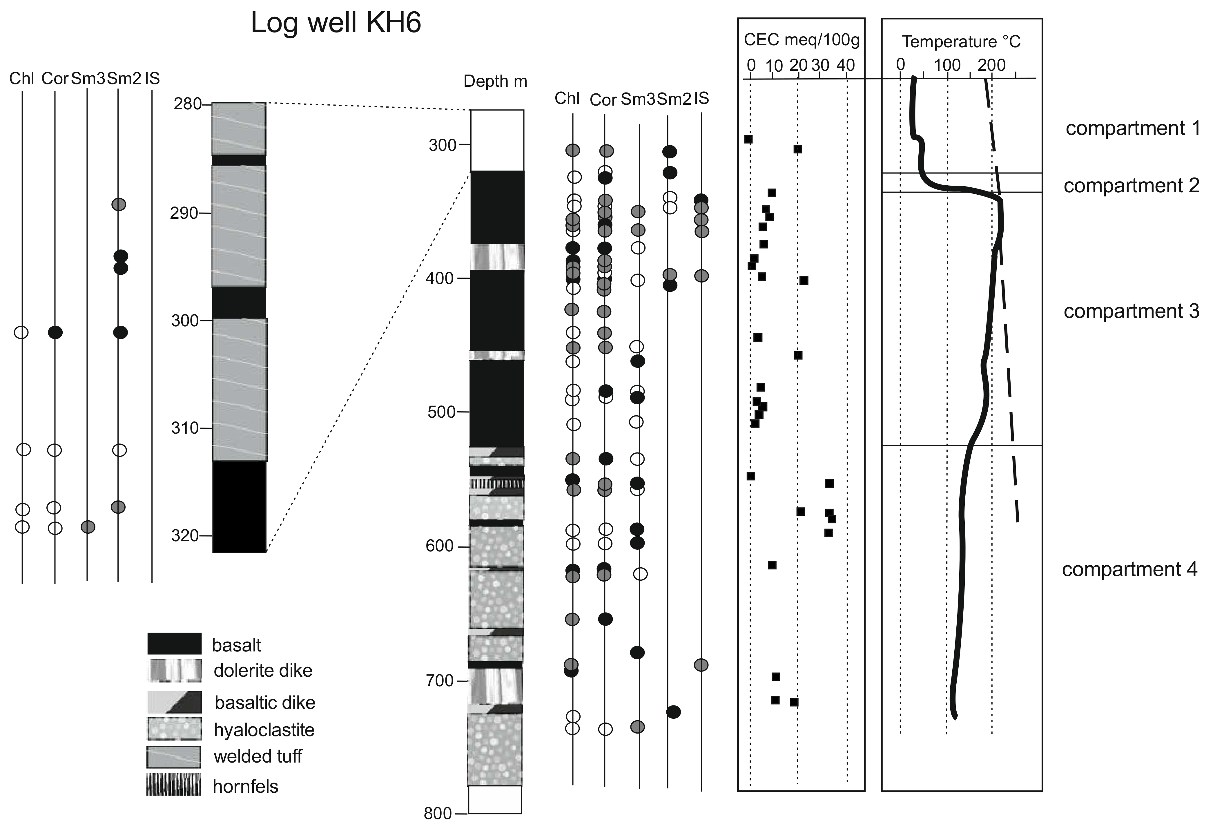
4.1. Lithology and Temperature of the KH6 Drill Hole

Macroscopic and microscopic observations of the selected samples helped to create the proposed lithological log (Figure 4), which is in agreement with the log established by [45]. The in-hole lithology is composed of basaltic tuffs and lavas in the upper part and hyaloclastite toward the bottom of the depth interval studied. All these formations are intersected by several basaltic and doleritic dikes and show evidence of clay-rich hydrothermal alteration throughout the well.
Basaltic rocks commonly have aphanitic to porphyritic textures dominated by pla-gioclase (labradorite/bytownite) and clinopyroxene phenocrysts (diopside/augite) embedded in a microlithic matrix composed mostly of plagioclases and clinopyroxenes. These volcanic rocks present millimeter-sized vesicles commonly filled with clays, quartz and/or calcite and zeolite minerals. The other dominant types of lithology are hyaloclastite resulting from subaerial eruptions in glacial environments and composed mostly of cryptocrystalline altered glass and mm- to cm-sized basalt clasts that account for 10–20% of the total rock volume. The basaltic glasses found in these environments are typically sideromelane and tachylite forms [46]. Sideromelane glass is the most abundant primary constituent of hyaloclastites and has been partially to completely altered. Alteration consists of dissolution and partial replacement of glass by secondary phases such as palagonite (amorphous alteration products ± smectite), clay minerals, zeolites, or carbonates. Altered hyaloclastite rocks are highly porous (20–30%, see [4,19]) and cover approximately 150 m of the well.
Both basaltic and hyaloclastite rocks are intruded by basaltic and doleritic dikes. Do-leritic rocks are coarser grained and less porous than the basaltic rocks but have the same mineralogical composition as basaltic rocks, with 60 to 80% plagioclase and clinopyroxene as essential minerals and subordinate quartz and magnetite.
A temperature log (Figure 4) was performed immediately after drilling completion [45]. Even if temperatures had not completely equilibrated, the thermal pattern recorded from in-hole temperature measurements indicates four different compartments throughout the well:
-
The first compartment (compartment 1, as indicated in Figure 4) is located from the surface down to a 300–320 m depth, where the temperature was stable at approximately 20–40 °C. This level constitutes the upper part of the drill hole where thermal transfers are mainly convective (low vertical thermal gradient). In this interval, the lithology is dominated by altered to strongly altered tuffs with some intercalations of poorly altered basalts. Outside the basaltic intercalations, the porosity reaches 35% and is mainly linked to the microporous clay matrixes. The bottom of this interval corresponds to a major change in lithology.
-
The second compartment, which is ten to twenty meters thick, corresponds to dominant basaltic lavas with the occurrence of an intercalated doleritic dike at a 324 m depth. Along this interval, the temperature abruptly increased to reach a maximum temperature of 215 °C, which exceeds that of the boiling curve of geothermal fluids near 350 m depths. Associated thermal transfers are mainly conductive, and this compartment seems to act as a cap for the deeper high-temperature geothermal system.
-
Below 350 m and above approximately a 530 m depth (compartment 3), the tempe-rature slightly and progressively decreased to 180 °C to a 475 m depth and increased again up to 190 °C near a 490 m depth before sharply decreasing to a 550 m depth. The shape of the thermal gradient in this zone suggests that this level is affected by fracture-controlled circulation of hot fluids close to boiling conditions. This compartment corresponds to a fractured reservoir with a lateral recharge of hot fluids. The lithology consists of basaltic lavas intercalated by two doleritic dikes. This compartment includes (in its upper part) the main fractured zones identified in the well. Due to fracture-controlled alteration, the porosity of the rocks in this compartment is variable, with values ranging from 5% to 35%.
-
Below a 550 m depth (compartment 4), the temperature is nearly constant (125–130 °C) until the well bottom. This shape of the thermal gradient is associated with convective thermal transfers. In this compartment, the lithology changes drastically with the predominance of hyaloclastic breccias originating from subglacial eruptions. Fractures are scarce, but the still high porosity (25–30%) and permeability can be explained by the textural properties of the rocks.

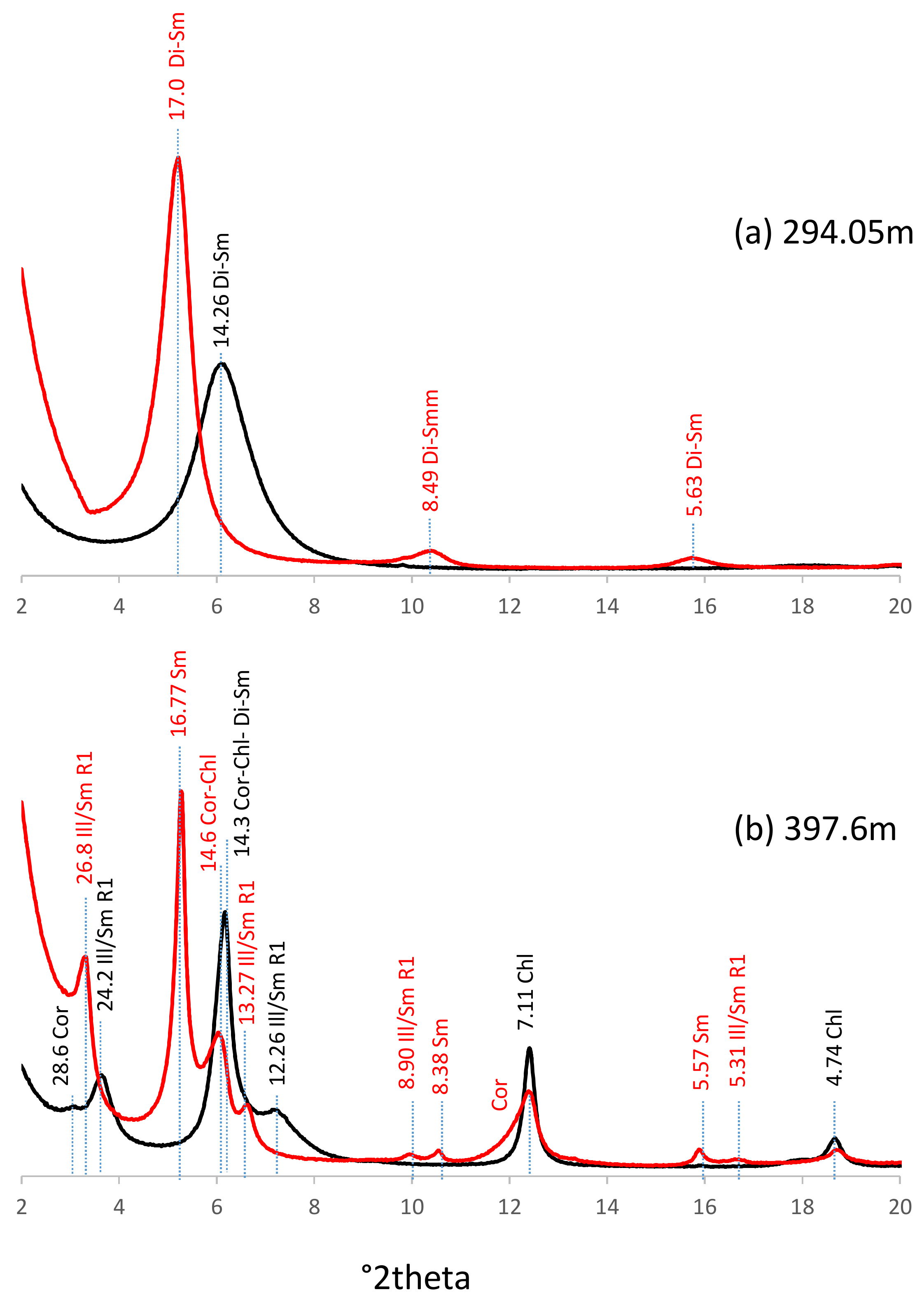
4.2. X-ray Identification of Clay Species

Almost all core samples analyzed display evidence of clay alteration at different grades. In strongly altered rocks, clay minerals may account for more than 50% of the rock volume. Throughout the drill hole, clay minerals consist predominantly of saponite, corrensite and chlorite (Figure 5a–c). These minerals are known to constitute the trioctahedral clay mineral series involved in the chloritization process in subsurface geological systems ([47] and references therein). More locally, occurrences of kaolinite, dioctahedral smectite and illite/smectite-mixed layers (Ill/Sm) are also observed (Figure 6a,b).
These minerals were identified using X-ray diffraction from oriented AD and EG clay fractions according to the recommendations of [48]. Saponite was identified from basal spacings close to 16.7–17, 8.3–8.5 and 5.6 Å on oriented mounts after EG treatment. Corrensite, which is a regular 1:1 chlorite/smectite mineral, was characterized from rational 00l peaks at approximately 31, 15.3, 7.75, 5.16 and 4.43 Å after EG solvation. Chlorite was identified by rational basal spacings close to 14.2, 7.1 and 4.73 Å; reflection profiles were unchanged upon EG solvation. If saponite, corrensite and chlorite are the predominant trioctahedral clay minerals in the altered samples, XRD patterns also show evidence of mixed layering between chlorite and an expandable phase. The presence of broad and (often weak) peaks between d002chl (7.1A) and d004cor (7.75), and between d003chl (4.74) and both d006cor (5.16) and d007cor (4.43) reflections after EG saturation (Figure 7), supports the presence of chlorite/corrensite-mixed layers (Chl/Cor) [11,49].
Dioctahedral smectite and saponite have essentially similar basal spacings. Distinction between di- and tri-smectite can be obtained by their 06–33 reflection positions, which range from 1.49 to 1.50 Å and from 1.52 to 1.54 Å, respectively. Regular illite/smectite (~1:1 Ill/Sm R1 with a maximum possible degree of ordering) was characterized by a super-reflection close to 27 Å and by a rational series of 00l peaks at approximately 13.5, 8.9 and 3.34 Å after EG treatment. Finally, kaolinite was identified by 00l reflections close to 7.14 and 3.58 Å.

4.3. Vertical Distribution of Clay Species

The clay distribution is summarized in Figure 4 and presented by compartments.
The first compartment, which corresponds to altered or strongly altered tuff, is cha-racterized by a predominance of dioctahedral smectite (±kaolinite) and minor amounts of corrensite and chlorite (+Chl/Cor). Trioctahedral smectite is only observed at the base of the unit in basaltic lavas whose alteration is weaker than in tuffaceous rock.
Only one sample was collected in compartment 2 in the doleritic dike. It contains both corrensite and chlorite (±Chl/Cor). No dioctahedral clay phases were identified in this sample.
The third compartment, which corresponds to an upper reservoir where porosity is controlled by fractures, contains variable amounts of clays with variable mineralogy. It can be divided into two parts: above and below 410 m (highest temperature zone). The upper part is characterized by both dioctahedral and trioctahedral clay minerals. Dioctahedral clays are represented by dioctahedral smectites at the top and base of this zone and Ill/Sm in the total domain (except in the doleritic dike). In the doleritic dike, chlorite (+Chl/Cor) and corrensite are the dominant trioctahedral clay phases. Below 410 m, only trioctahedral phases are observed with dominant trioctahedral smectite and corrensite relative to chlorite.
The fourth compartment does not contain dioctahedral clays except in one hornfels sample situated close to a doleritic dike. This compartment is dominated by trioctahedral clay phases with variable amounts of saponite, corrensite and chlorite. Nevertheless, sa-ponite seems to dominate in hyaloclastic formations, while chlorite and corrensite dominate in intercalated lavas or dikes.
From these results, it appears that the hydrothermal mineralogy in the KH6 drill hole is more variable than previously supposed and that the so-called “smectite-zeolite” zone, which corresponds to the temperature range of KH6 (30–215 °C), is complex and consists of several paragenetic assemblages that were superimposed at the scale of the petrographic thin section. Regardless of the temperature, chlorite and corrensite were observed throughout the drill hole, including the upper low-temperature compartment. Accor-ding to the literature on geothermal systems, whereas dioctahedral smectites are generally found at temperatures lower than 100–150 °C and more occasionally up to 200 °C, trioctahedral smectites may occur throughout the temperature range measured in the KH6 well [50]. In the KH6 well, dioctahedral smectites and Ill/Sm were identified at depths between 300 and 420 m, where the highest fluid temperatures were reached (215 °C).

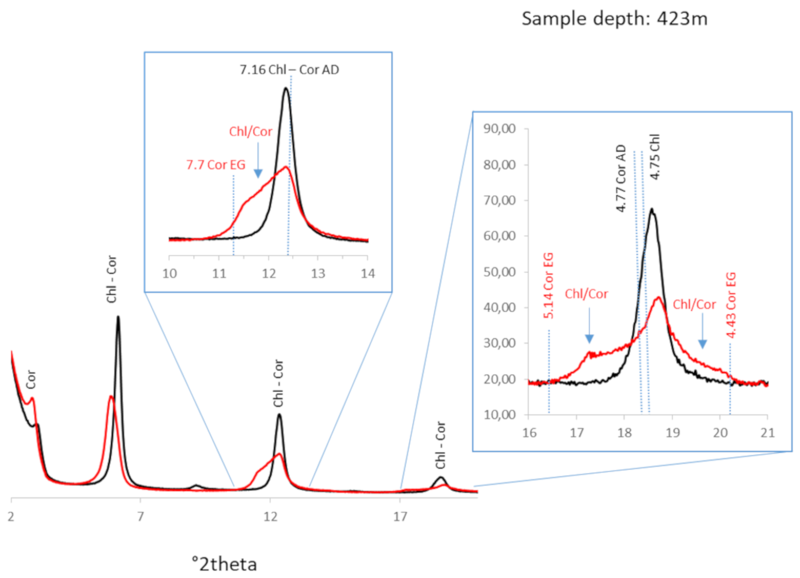
4.4. Alteration Parageneses

From petrographic observations, several alteration stages were observed. The first alteration stage is characterized by the crystallization of chlorite and corrensite (+Chl/Cor). Chlorite (+Chl/Cor) was found, associated with corrensite, throughout the interval of study in all compartments and in all types of lithology: basalts, hyaloclastites and basaltic/doleritic intrusives even in the upper part of the well. These trioctahedral minerals developed mostly inside gas cavities (vacuoles and vesicles) and pore spaces, such as dikytaxitic voids or dissolution voids, within the rock (Figure 8). They precipitated from fluids that interacted with the glassy groundmass of the rocks. Indeed, they crystallized in open spaces with drusy organizations, but glass near the contact was replaced by trioctahedral clay minerals and titanite (Figure 8). In addition to clay minerals, the filling of the cavities may consist of quartz, calcite and/or zeolite, wairakite and Na-rich feldspars. These cavities infilled by alteration products are also found in samples with no connection to fractures, in which there is partial preservation of fresh basaltic glass (in hyaloclastite formations).
A second alteration stage is expressed by trioctahedral smectites (Figure 9). These smectites occur in all compartments but dominate in the deeper compartment (4th), where hyaloclastites are abundant. Indeed, even if they occur in both basaltic (lavas and dikes) and hyaloclastite rocks, they are predominant within this last group. In basaltic rocks, saponite is found mostly within the volcanic rock mesostasis in replacement of the in-terstitial glass or partial replacement of primary minerals. It postdates the chlorite and corrensite (or Chl/Cor), which filled vugs earlier (Figure 9). In the case of hyaloclastite rocks, saponite is primarily related to glass alteration.
Close to intrusions of basaltic dikes, hyaloclastite rocks could also contain minerals indicative of contact metamorphism, such as garnet (grossular-andradite) and/or actinolite [51].
The two aforementioned alteration stages are found extensively over the 727 m of well cores studied, in which the present temperature ranges from 40 to 215 °C, with no relationships with permeable fractures (pervasive alterations).
Three different clay parageneses associated with horizons affected by fracturing were observed in the upper part of the interval (top of the third compartment described above).
(1)
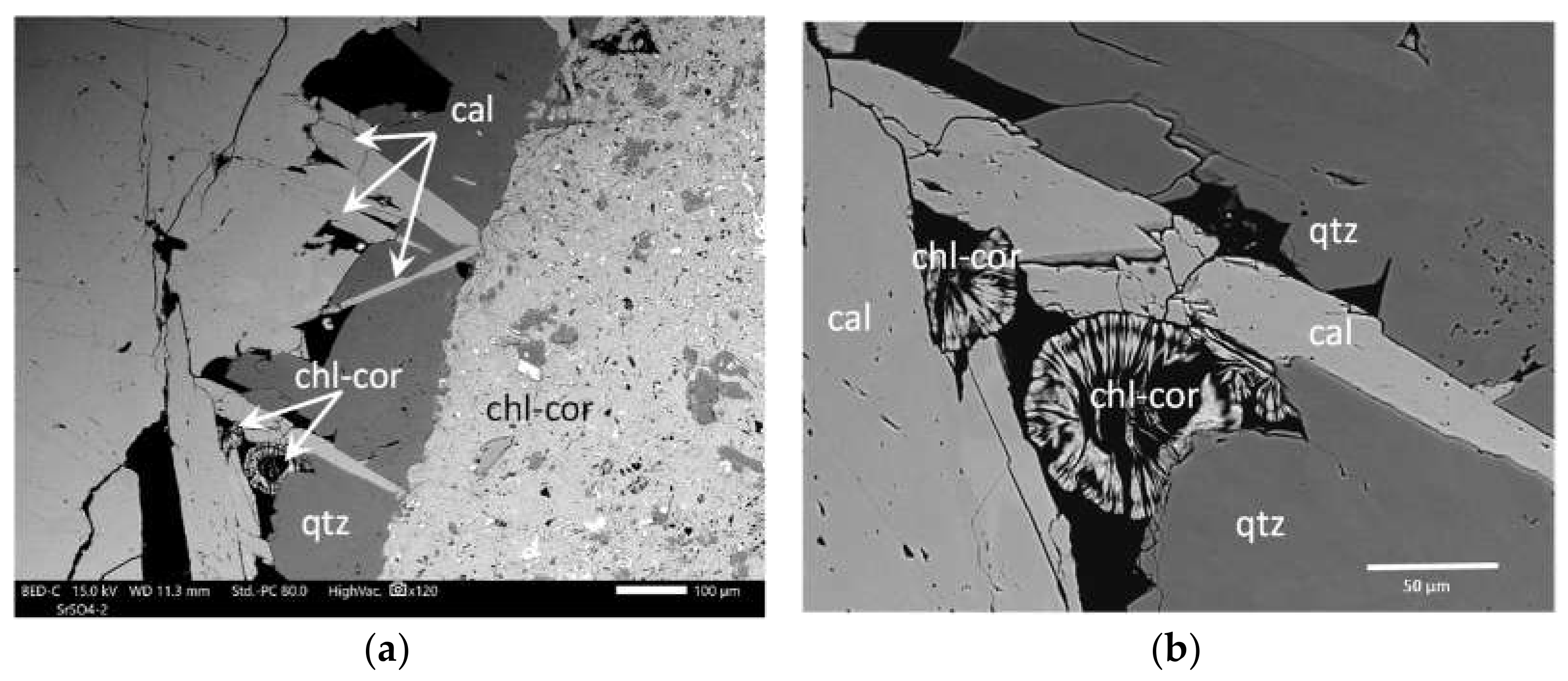
A first stage of argillization linked to fracture-controlled fluid circulation (vein infillings) is expressed by coprecipitation of chlorite (+ Chl/Cor), corrensite, platy calcite and quartz with some “feathery” habits (Figure 10). It is particularly developed in the third compartment at a depth of approximately 425 m. Chlorite and corrensite (+ Chl/Cor) are very abundant alteration products of the wall rock in which they have replaced all mesostases and most coarser-grained primary (or secondary) minerals.
In fractures, small amounts of chlorite and corrensite (+Chl/Cor) were observed as spherules that formed contemporaneously with the calcite and quartz crystals, whose texture (bladed calcite, recrystallization texture of quartz) is characteristic of crystallization under boiling conditions.
Trioctahedral smectites occurred farther from the veins. As chlorite (±corrensite) mi-nerals crystallized inside and at the selvage of hydrothermal veins that overprinted the saponite-rich pervasive alteration observed throughout the rock mesostasis, we can infer that at least one generation of saponite was present before the hydrothermal alteration related to open fractures.
(2)
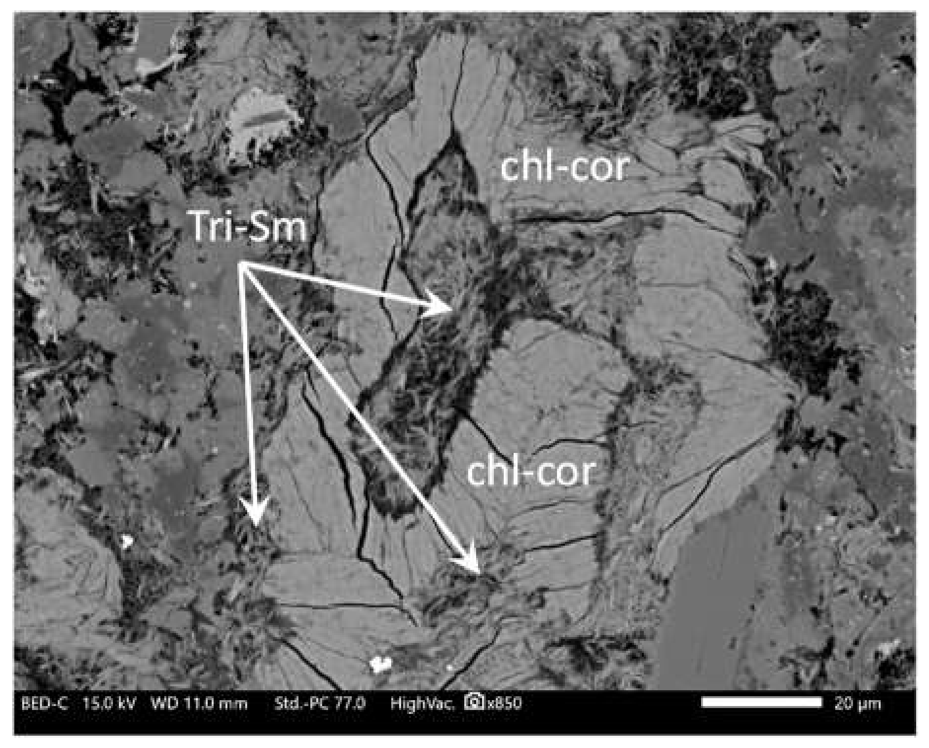
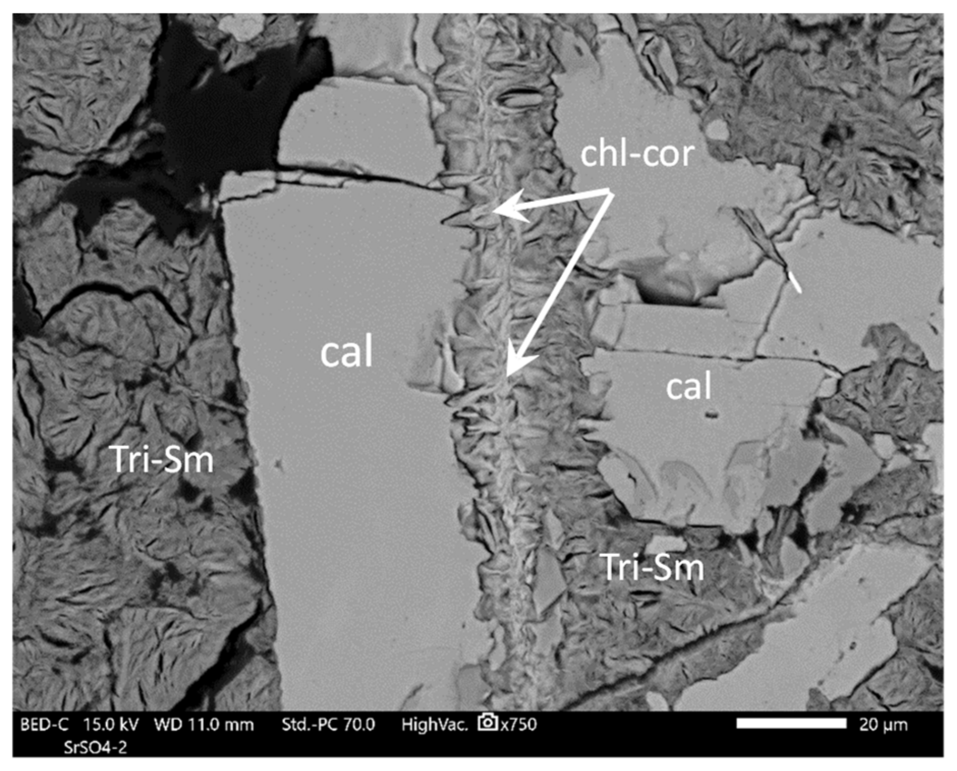
An alteration stage with trioctahedral smectite + calcite + quartz as vein infillings is also observed locally. Its relationships with chlorite-bearing veins are complex, suggesting that both types of veins are contemporaneous. Sometimes saponite veins postdate chlorite veins, while chlorite (±Chl/Cor) veins seem to postdate saponite veins in other places (Figure 11).
(3)
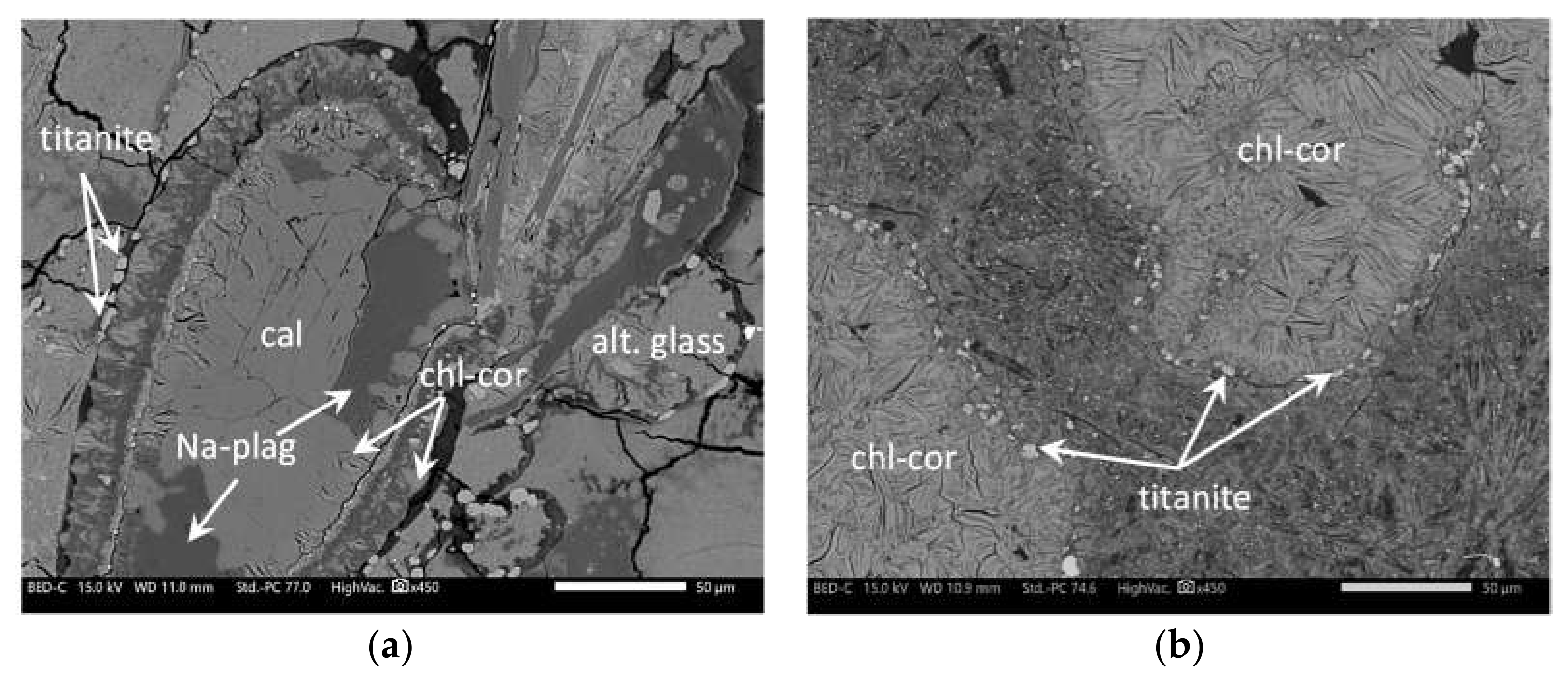
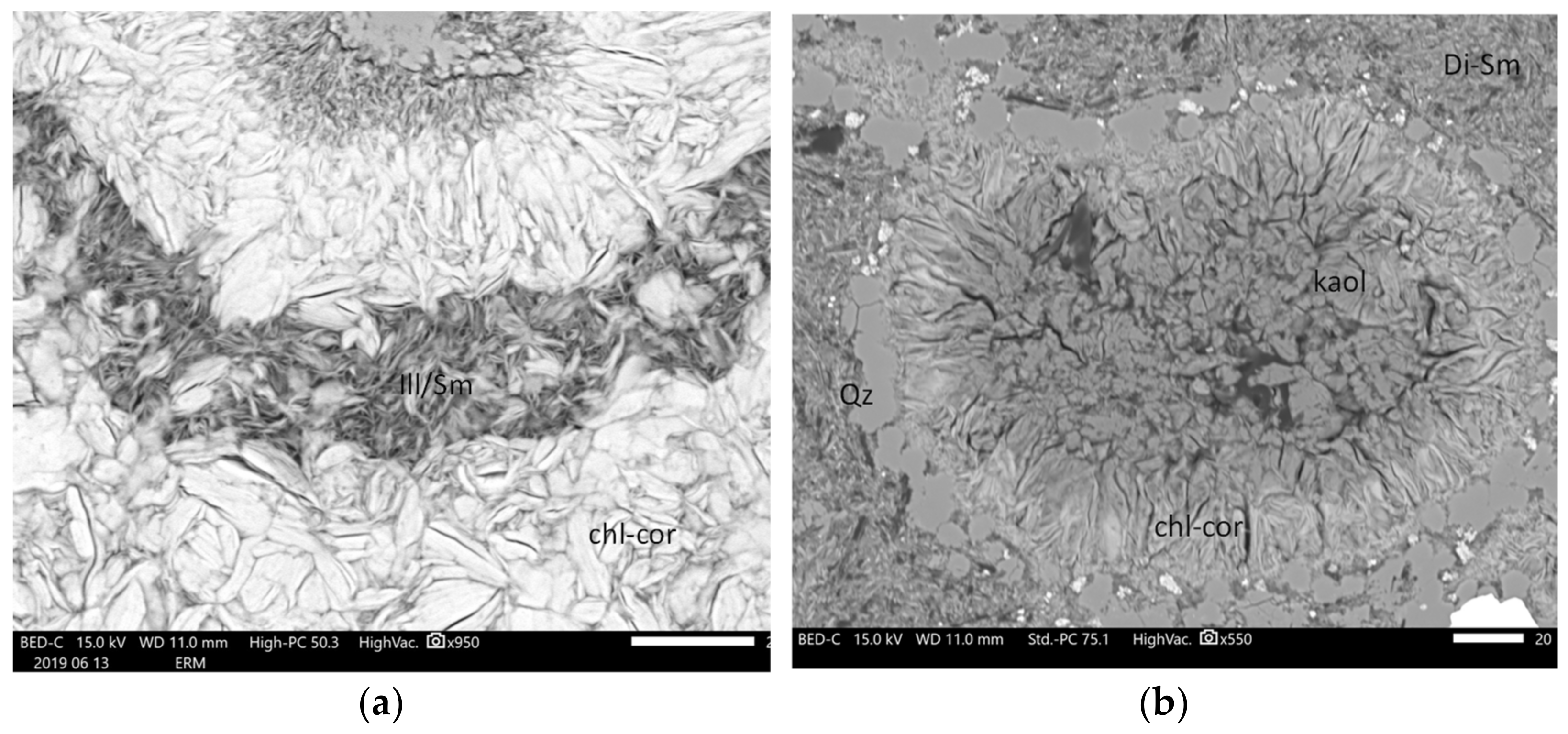
Another paragenetic assemblage, located at the top of the studied section (first and third compartments), is expressed by the crystallization of aluminous clay minerals, including dioctahedral smectite, Ill/Sm and scarce kaolinite. Ill/Sm are observed at the top of the third compartment from 340 to 400 m depth, mainly in the replacement of plagioclase microlites or as veinlets crosscutting earlier aggregates of chlorite-corrensite minerals (Figure 12). Aluminous smectites are observed in the first compartment and on the top and base of Ill/Sm zones. They replace feldspar microlites in basaltic lavas. These zones are highly altered with almost complete replacement of primary minerals. Kaolinite is observed in one sample in the first compartment (Figure 12). This event is associated with intense leaching of the basaltic rocks and tuffs, which resulted in strongly argillized rock (compared with deeper compartments) and is not related to felsic rocks. Aluminous clay minerals are associated with quartz and calcite ± pyrite.

4.5. Crystal Chemical Properties of Clay Minerals

4.5.1. Chloritic Phases

Chlorite, corrensite and Chl/Cor are intimately associated in vugs, veins and replacement of the mesostasis. As a consequence, among all SEM/EDS point analyses of chlorite-like minerals, it was not possible to obtain a chemical analysis of pure chlorite.
All analyses indicate the presence of low but significant amounts of Ca, which is indicative of mixing and/or mixed layering of chlorite with expandable trioctahedral clay minerals such as corrensite or saponite. The lowest value obtained for the interlayer charge was 0.04 aphfu (atom per half formula unit) (Table 1), and the average was close to 0.2, suggesting systematic mixing or mixed layering with expandable trioctahedral phyllosilicates. Regardless of their crystallization site and the amount of corrensite in the mixture, the Fe/(Fe + Mg) ratio is very variable (0.40 to 0.63 for corrensite-rich mixtures; 0.45 to 0.62 for chlorite-rich mixtures), with average values of 0.51 and 0.52 for the corrensite-rich and chlorite-rich mixtures, respectively. No distinction can be made between chloritic minerals in vugs and in replacement of the mesostasis. Octahedral occupancies of chlorite are lower than 6 aphfu due to intimate mixing or mixed layering with corrensite. For “almost pure” chlorite analyses (no interlayer cations), the octahedral occupancies reach 5.9 aphfu, confirming the tri-trioctahedral nature of chlorite (Figure 13a).
For almost pure corrensite (octahedral occupancy close to 9 aphfu), the layer charge of the smectite layer is approximately 0.6 (Table 2 and Figure 13b).

4.5.2. Trioctahedral Smectites

The octahedral occupancy is close to 3 aphfu (2.90 to 3.1) (Table 3). The Fe/(Fe + Mg) ratio is very close to that mentioned previously for chlorite and corrensite and ranges from 0.42 to 0.63 with an average value of 0.57. The interlayer charge (due to important Si4+/Al3+ substitutions in the tetrahedral sheet), which averages 0.6, is mainly compensated by Ca and Na, and the proportion varies between the two. The highest proportions of Na cor-respond to smectites developed in the mesostasis of the doleritic intrusion.

4.5.3. Dioctahedral Smectites

Dioctahedral smectites have different compositions according to their location (Table 4). Dioctahedral smectites located in the cap rock are richer in magnesium and silica than smectites located at the base of the Ill/Sm alteration zone (0.2 versus 0.1 Mg aphu) (3.7 against 3.5 Si aphfu), suggesting a montmorillonitic to beidellitic trend with increasing temperature. Fe is always low even if it seems slightly higher in surficial smectites. Both smectites have intermediate layer charges (approximately 0.40 phfu) compensated by Na and Ca cations and K (in the more beidellitic smectites).

4.5.4. Illite/Smectite

Ill/Sm corresponds to regular mixed layers with a composition close to 1:1. Their interlayer charge is approximately 0.7 phfu, mainly compensated by K cations. Si is close to 3.3 aphfu, suggesting that the layer charge is linked to substitutions in tetrahedral sheets and that smectite is a highly charged beidellitic smectite. Mg is the main divalent cation in the octahedral sheet (0.10–0.17 aphfu) (Table 4).

5. Discussion

5.1. Chronology of Hydrothermal Events and Associated (Paleo) Conditions

In this study, the first distinction we used to classify clay mineral assemblages was based on whether they occurred in an open or in a rather closed chemical system. We define highly permeable fracture-controlled horizons or zones in which mineral reactions proceeded under an active flow regime and resulted in vein alteration as open alteration systems. Conversely, in closed alteration systems, mineral reactions proceeded by the interaction of rather stagnant fluids with the reactive minerals of host rocks and mostly resulted in pervasive alteration.
From the petrographic data and the mineralogy of altered rocks presented herein, it appears that clay alteration in the KH6 drill hole is a composite of four different mineral assemblages that may have been sequential in time and frequently superimposed in space. These assemblages provide insight into the vertical variation in the hydrothermal alteration and related subsurface, past to present, dynamics of geothermal fluids in the northwestern zone of the Krafla geothermal field. The first two assemblages are related to alteration processes that do not present any direct relations with fluid flow in permeable fractures.

5.1.1. Earlier Chlorite-Corrensite Assemblage

In all compartments, petrographic observations confirm that infilling of gas cavities by chlorite-corrensite is the first hydrothermal stage generating clay minerals. In addition to trioctahedral clays, quartz, wairakite, zeolites, pyrite and Na feldspars are sometimes identified (especially in hyaloclastites). The fact that chlorite-corrensite occurred as vug infillings without any significant alteration of the glass (except in a thin rim around the cavities), as illustrated in some hyaloclastites, suggests that this argillization stage is not related to fluid flow in narrow drains or fluid/rock interactions related to external downward fluid infiltration of surficial waters. Indeed, according to the experimental work of [52], the hydrothermal alteration of glassy fragments of hyaloclastites is very fast, from a few hours to a few years. The alteration of a thin layer of glass at the interface between cavities and glass is evidenced by the occurrence of Ti-rich minerals (anatase and titanite) which concentrate immobile elements [52,53,54]. Therefore the clay minerals occurring in cavities can then be understood as a result of both direct precipitation from trapped fluids and glass alteration at contact. The fact that some cavities are totally filled by secondary minerals also confirms that alteration is not limited to mineral precipitation related to cooling of trapped fluids. This paragenesis has already been described by [10], who observed the association of chlorite, quartz, carbonates, alkali feldspars and pyrite as pore-filling material resulting from tardi-magmatic precipitation in quartz-syenite hypabyssal sheets.
This type of chlorite-corrensite assemblage is found throughout the four compartments, including the upper part of the well currently infiltrated by low-temperature fluids (except tuffaceous formations). As the formation temperatures of corrensite and chlorite are well known to exceed 150 and 200 °C respectively ([47] and references therein), these clay minerals must be linked to an earlier HT event (late to tardi-magmatic stage) in a relatively closed system. As found by [10], we consider here that chlorite-corrensite in vugs results from the interaction of an exsolved volatile-rich supercritical fluid (tardi-magmatic fluid) with the glass material of the host rocks. The glass alteration would have provided the Al, Fe, and Mg (±Ca) required for the sequential crystallization of chlorite-corrensite minerals and finally carbonates or zeolites.
Regarding temperature, if chlorite can be observed up to 500 °C in a “closed” metamorphic environment [55,56,57], corrensite and Chl/Cor generally occur at temperatures between 150 and 250 °C even if the presence of corrensite has been noted at temperatures of up to ~300 °C [47,58,59]. Nevertheless, they can be synthesized at much higher temperatures (up to 500 °C; [60]) as metastable phases. Occurrences of disseminated garnet (grossular andradite) in the altered glass, even if they are the product of thermal metamorphism around doleritic dikes, also confirm temperatures temporarily higher than 300 °C [61,62].

5.1.2. Pervasive Replacement of the Groundmass by Trioctahedral Clay Minerals (Chlorite, Corrensite, and Smectite)

Trioctahedral clay minerals replacing the groundmass are common in nonfractured altered basaltic rocks. This clay mineral assemblage is controlled by host rock chemistry, which favors the formation of trioctahedral clays, in this case saponite, corrensite and Fe-Mg chlorites (and their mixed layers) [63]. These clay minerals occur in the mesostasis of basalts, dolerites and hyaloclastites and throughout almost all studied samples, except at the top of the first compartment.
The semi-quantitative estimations of clay mineral phases deduced from X-ray diffraction on randomly oriented powders show higher smectite content in hyaloclastites than in crystalline rocks, and conversely, chlorite content is usually higher for crystalline samples (Figure 14). The spatial distribution of the trioctahedral clays is not correlated with hole temperature or depth, as usually observed in the classical pattern of clay mineral distribution ([20,21,22,23], among others).
The unusual vertical alteration zoning observed in the KH6 drill hole with dominant chlorite-like minerals in the upper part and dominant trioctahedral smectite at greater depths, where hyaloclastite is abundant, is likely due to the control of lithology on clay alteration.
Regarding temperature, considering the thermal range studied (if we exclude the first compartment), both trioctahedral smectite, corrensite, Chl/Cor and chlorite can co-exist. Indeed, chlorite can form at approximately 200 °C, while corrensite is generally observed between 150 and 300 °C and saponite up to 300 °C ([47] and references therein). Despite the local occurrence of high-temperature minerals such as garnet in hyaloclastite rock, alteration of the glass was mainly smectitic. Therefore, the direct use of clay mine-ralogy as a temperature indicator must be treated with caution.
As the Si/Al ratio is higher in saponite than in chlorite [64], rock chemistry could be a key factor controlling the predominance of smectite or chlorite in a closed system (without taking into account the temperature). Indeed, this ratio in basaltic glass is greater than that in crystalline basaltic rocks, which could explain how lithology affects the predominance of smectite or chlorite. Smectite is also a common product after hydration and alteration of basaltic glass. Indeed, it is generally accepted that palagonite (±zeolites or carbonates) is the first metastable product resulting from these processes, which can develop at temperatures as low as ambient temperatures [65,66] and whose main component is smectite (nontronite and/or saponite).

5.1.3. Clay Minerals Related to Fracture-Controlled Fluid Circulation

In the upper part of the interval of study (down to 500 m), some horizons are affected by fractures and a connected network of microcracks that created a permeable medium that enhances the circulation of fluids and aqueous species.
Two different clay parageneses have been distinguished: (1) clay minerals resulting from direct precipitation from geothermal fluids; and (2) clay minerals formed after dissolution of reactive minerals and leaching of mobile elements from the host rock.

Clay Minerals Resulting from Direct Precipitation from Geothermal Fluids

Vein infilling is characterized by chlorite-corrensite spherules associated with bladed calcite and feathery quartz that are indicative of precipitation from boiling geothermal fluids [67]. These veins are observed at approximately 400–500 m depth (which coincides with the bottom of the thermal anomaly) with a present-day temperature close to 200 °C, only slightly lower than the current boiling conditions. This alteration event can then be considered to have been very recent. The crystal chemistry of the chloritic phases (especially the Fe/(Fe + Mg) ratio) is similar to that previously described in trioctahedral clays, suggesting that the geothermal fluid was close to chemical equilibrium with the hosting basaltic rocks (we speculate this may owe to the boiling of resident fluid). The amount of clays resulting from direct precipitation in veins is low, whereas chloritic phases predo-minate in the wall rock alteration halo as the result of dissolution/recrystallization processes instead of saponite, which is observed farther from the vein.
The occurrence of trioctahedral smectite + calcite is also observed locally, but their relationships with this event are not clear.

Clay Minerals Associated with Intense Leaching of the Host Rocks

The occurrence of dioctahedral clay minerals is poorly documented in Icelandic geothermal systems; however, they were mentioned by [68,69]. In basaltic environments, the massive crystallization of Al-rich phases must be the result of strong hydrolysis of basaltic minerals (Ca-rich plagioclases and clinopyroxenes) and glass in open systems combined with strong leaching of mobile elements such as Na, Ca and Mg. This leaching is favored by moderately acidic solutions, which results in important dissolution of primary mineral phases. Because KH6 rock samples are mostly dominated by plagioclases and basaltic glass, the major immobile element after dissolution is aluminum; therefore, aluminous clay minerals such as dioctahedral smectite, kaolinite or Ill/Sm will be good markers of this phenomenon.
A low pH environment can be generated when vapors (H2O, H2S, CO2, and HCl), released from depressurization boiling, mix with meteoric groundwaters that contain atmospheric oxygen [70], thereby oxidizing H2S to SO42−. This results in a strong drop in pH (i.e., 2–3), which triggers the acidic leaching of near-surface zones [52]. Under these acidic conditions, Ca-rich plagioclases that were not affected by previous alteration stages (contrary to basaltic glass) tend to dissolve, providing Al for the crystallization of Al-rich clay phases. These aluminous clays are commonly associated with quartz and calcite (and sometimes pyrite).
In well KH6, there are several zones displaying hydrothermal alteration by mode-rately acidic fluids (compartment 1 and top of compartment 3). This observation is consistent with the hydrological model [38]. These authors observed a large spatial variation in the stable isotope composition of geothermal fluids, which was explained by the ascent of steam from a deep aquifer zone into a shallower zone of sub-boiling water and their mixing in variable proportion.
The spatial distribution of regular Ill/Sm, which coincides with the present-day boi-ling zone, suggests that crystallization of Ill/Sm is still active. Moreover, the upper temperature range for these phases is generally close to 200 °C [71,72], suggesting that these phases are not linked to retrograde metamorphism [68]. These phases have also been observed in the Jökulhlaups deposit and are considered as a low-temperature (100–140 °C) hydrothermal alteration of basaltic material within the subglacial environment [73]. Occurrences of Ill/Sm suppose a strong leaching of Mg, Ca and Fe, which necessarily involves a strong W/R ratio (and hence strong renewal of the solutions).
The occurrence of Al-smectite and Ill/Sm can be explained both by temperature conditions and the aK+/aH+ activity ratio. Al-smectite is observed mainly on both sides of the Ill/Sm domain (maximum present-day temperature of approximately 215 °C) and in the top compartment: montmorillonite is observed in compartment 1 at approximately 40 °C, and beidellite is observed at higher temperatures (compartment 2) up to the Ill/Sm domain at temperatures close to 200 °C. Several authors have suggested a close relationship between formation temperature and the crystallochemistry of hydrothermal smectites. The existence of thermal control of the nature of dioctahedral smectites has been documented in the Chipilapa geothermal field [74]. In this field, beidellite is only found in reservoir areas located between 500 and 1200 m deep and in which the average temperature is approximately 200 °C; whereas montmorillonite-type smectite is only encountered on the surface at temperatures below 130 °C. In the Ohaaki-Broadlands geothermal system, [75] the presence of montmorillonite in the superficial parts of the field and a tendency for beidellite enrichment with increasing depth and temperature have also been noted. The same type of observation was made by [76] in the geothermal field of Kakkonda. Nevertheless, increasing the W/R interaction with basaltic rock could also be the source of increasing Mg input. Indeed, in the Bouillante geothermal field [77], montmorillonite resulted from interactions of both geothermal and meteoric fluids with andesitic rocks, providing a Mg supply, while beidellite resulted from a direct discharge from the high-temperature geothermal fluid, depleted in Mg.
The smectite to kaolinite transition is poorly constrained by temperature but strongly controlled by pH or leaching intensity (i.e., W/R ratio) [78,79,80,81]. If the pH of geothermal fluids in the Krafla area is typically near neutral (~6–7), a massive influx of magmatic gases can result in pH values as low as 2 in some places. Nevertheless, this mineral is seldom in the studied section (only one occurrence). These clay minerals have already been reported in acidic sulfate alteration developed at the surface in Krafla geothermal areas; the Al smectitic component is observed on the margin of acid sulfate fumaroles and hot springs, while kaolinite is related to fumarolic alteration [82]. Here, the absence of strong gas influx is evidenced by the absence of major sulfate minerals and the predominance of montmorillonite over kaolinite. According to [69], smectite and kaolinite are indicators of intermediate argillic alteration, typical of slightly acidic pH and temperatures lower than 200 °C. Kaolinite-rich zones correspond to conduits for acidic hydrothermal fluids, whereas the fluids infiltrating the surrounding rocks were progressively neutralized as water-rock interactions progressed.

5.2. Relationships between Hydrothermal Alteration and Hydrodynamics

Except for the earlier alteration that had been active in the past throughout the entire studied section of the KH6 drill hole, the recent hydrothermal alteration is strongly dependent on the present hydrodynamics of geothermal fluids in the system. Hydrodyna-mics are controlled by lithology through the petrophysical properties of the rocks. Indeed, the nonfractured basaltic lavas and dolerite intercepted at depths of approximately 300–320 m by the KH6 drill hole (compartment 2) constitute a thermal barrier and act as cap rock for a shallow reservoir. In compartment 1, located just above the caprock, fluids heated by conduction at the contact of the basaltic lavas interact with the host tuffaceous rock. Heat transfer seems convective inside this permeable compartment characterized by very high matrix porosity (35%). The abundance of aluminous smectites and kaolinite suggests a strong chemical disequilibrium between basaltic rock and fluid and a high fluid/rock ratio characteristic of open systems. This alteration requires near neutral to acidic aqueous fluids and temperatures lower than 100–120 °C. The main clay phases identified are montmorillonite and subordinate kaolinite.
A shallow reservoir is hosted in fractured basalt (compartment 3), and this reservoir is laterally recharged in connection with the major permeable fracture network. Currently, the temperature is close to boiling conditions. The small quantities of trioctahedral clays (chlorite-corrensite) that fill the open cracks, in addition to feathery quartz and lamellar calcite, precipitated directly from the liquid phase which was oversaturated after expulsion of the vapor phase. The condensates of the vapor phase at the top of the reservoir generate acidic fluids that promote the formation of Ill/Sm and beidellitic smectite. The diphasic state of the hydrothermal fluid can explain the syn-crystallization of dioctahedral and trioctahedral clays (same moment but in different places). Considering the present-day temperature, this alteration stage is probably very recent (temperature is 25 to 40 degrees below the boiling temperature, in the absence of any decrease in hydrostatic pressure due to fracture opening). Separated from this shallow reservoir by aquiclude formations that consist of basaltic dikes and hornfels (approximately 530–560 m depth), hyaloclastic formations can be considered a deeper reservoir with low- to moderate-temperature fluids (125–130 °C) and very high permeability (gas permeability on the order of mDa and water permeability of 10−3–10−2 mD according to [83]). In these formations (compartment 4), the porosity is high (20–30%) but mostly related to matrixial porosity and brecciated rocks. These formations are not linked to the main recharge of HT geothermal fluid, as suggested by the strong decrease in temperature. Nevertheless, the vertical thermal gradient suggests the establishment of a convection cell; the fluid being close to che-mical equilibrium with the host rocks with occurrences of trioctahedral clays whose nature depends on lithochemical and petrophysical constraints.
Regarding the hydrothermal clays, trioctahedral smectite, corrensite, chlorite and attendant mixed layers are widespread. In the basaltic context, they are the main products of fluid rock alteration, and all of them may form in a relatively similar thermal range but result from several alteration processes, as confirmed by petrographic examination. Moreover, due to kinetic factors, the composition of clay minerals may be highly heterogeneous for a given alteration process. Under these conditions, it is challenging to state which clay species are in thermodynamic equilibrium with the fluids of the present geothermal reservoirs.
The fact that hydrothermal alteration is controlled by the evolution of the fracture network and attendant hydrodynamics of the geothermal fluids results in the absence of mineralogical zoning at a large scale, frequently described as a function of temperature (smectite, smectite/chlorite, chlorite, chlorite/illite, epidote, and actinolite zones with increasing temperature) in the Icelandic systems ([20,34,84,85,86], among others). The occurrence of large-scale alteration zoning is not in agreement with the strong variation in the W/R ratio related to hydrothermal aquifers and aquicludes. Franzson et al. [23] also mentioned the disagreement between the classical model and clay distribution in the Nesjavellir hydrothermal system. They clearly showed that clay mineralogy depends on rock permeability. In this system, smectite and interstratified clays (trioctahedral clays) are frequently observed within the chlorite and chlorite-epidote zones. This observation also supports the fact that temperature is not the only key parameter in interpreting the spatial distribution of clay parageneses [17]. Studies of the smectite to chlorite reaction pathway in hydrothermally altered metabasites also demonstrated that the degree of reaction progress was not linked to thermal gradients but to kinetic effects related to the fluid/rock ratio and contrast between advective and diffusive fluid transport. Here, pe-trographic examinations allowed us to determine present-day or very recent hydrothermal clay crystallization and associated hydrodynamics (“closed” versus open compartments, connections with major drains).

5.3. Implications for Geothermal Exploration

In recent decades, electrical and electromagnetic (EM) methods have been developed as high-temperature geothermal reservoir prospecting tools (e.g., [87,88,89,90,91,92]). These EM data, along with borehole data [90], served to create a general model of geothermal reservoirs by correlating temperature and resistivity measurements with hydrothermal alteration. Most high-temperature geothermal reservoirs within basaltic rocks, as is the case for the Icelandic context, present a similar 3D resistivity distribution, with the occurrences of a low resistivity anomaly at shallow depths (for temperatures ranging from 110 to 200 °C) underlain by a more resistive core (dominated by chlorite and epidote minerals and for which temperatures exceed 250 °C). However, the longevity of activity in the systems, which is expressed by successive pulses of water/rock interaction, as evidenced herein, leads to a single resistivity that integrates both active and fossil periods. Therefore, even if EM methods are an essential approach for obtaining 3D imaging of entire systems at the field scale, complementary data are needed to constrain the model by including their dynamics and weighing the contribution of past and present hydrothermal processes in the observed alteration patterns.
Based on the results obtained for the KH6 drill hole, two major issues must be noted:
-
First, both di- and trioctahedral smectites and/or expandable clay minerals are observed frequently and not strictly linked to cap rock formations. Indeed, smectites have been identified everywhere both close to the surface and at the base of the fracturated zone affected by current fluid flows (dioctahedral smectites) or as replacements of basaltic glass and vein infillings (trioctahedral smectites).
-
Second, chlorite and corrensite are also present everywhere and result from different hydrothermal processes, some of which are not representative of fluid circulation.
In the study area of the Krafla geothermal system, the cap is mostly composed of dioctahedral smectites, while in the palagonitized zones, the smectitic material is mainly trioctahedral. EM approaches will not be able to discriminate trioctahedral smectites resulting from palagonitization of basaltic glass from smectites strictly controlled by large-scale fluid circulation. Any approach to differentiate between these two types of smectites would help to discern the alteration zones related to diffusive fluid transport from those related to advective fluid transport.
Furthermore, it has been shown that the current (or subcurrent) fluid circulation at the highest temperatures (approximately 200 °C) generates, at depth, a chlorite/corrensite (and the possible presence or absence of trioctahedral smectites) + calcite + quartz assemblage that cannot be distinguished from pervasive early alteration. The only observable signature of current activity today is the presence of dioctahedral phases (especially Ill/Sm) at depths of 300–400 m, at temperatures close to their thermal stability range (i.e., 200 °C) and resulting from rock interactions with steam condensates from the boiling geothermal fluid. In the studied drill hole, Ill/Sm can therefore be considered relevant mi-neralogical markers of conduits that channel the fluid from deep HT reservoirs, as also identified in the Námafjall geothermal field [69]. This specific occurrence of dioctahedral clay minerals definitely indicates leaching of basaltic rocks and intense hydrothermal activity. The identification of these phases would then highlight connections with deep HT reservoirs.
A key point therefore seems to be the recognition and identification of secondary aluminous clay phases. XRD is a classical approach to identify these phases, but this technique requires regular sampling and remains expensive and time consuming. A field approach using alternative equipment such as portable X-ray fluorescence or SWIR (short wave infrared) would be preferable. The added value of the latter is that we would be able to distinguish the different dioctahedral clays (montmorillonite, beidellite, illite or kaolinite) on the basis of their absorption bands. This equipment, which is largely used by mi-ning companies, is still poorly developed in geothermal system prospecting and is most often used for qualitative approaches (determination of alteration zoning). However, quantitative development is feasible, as illustrated by [93,94], if a careful calibration is performed at the field scale beforehand. Therefore, combining EM surveys, which are mandatory to obtain 3D imaging of the field, and SWIR logging could be a very promising approach for geothermal system prospecting in the future and could achieve a better dynamic picture of these systems.

6. Conclusions

The vertical distribution of hydrothermal clay minerals in the 733 m deep well KH6 appears much more complex than the classical “smectite zeolite zone” described for <200 °C alteration zones. This “low” temperature zone, which is generally poorly studied in comparison with the “high” (i.e., >250 °C) temperature zones can nevertheless be very informative. The classical pattern described for Icelandic systems in the literature takes temperature distribution as the principal factor controlling clay paragenesis, but the spatial distribution of clay minerals does not seem to be constrained only by temperature, at least in the range of the studied interval, 30–220 °C. Generally, hyaloclastite rocks present more smectite minerals, and crystalline rocks develop more chlorite and corrensite mi-nerals.
Instead of temperature control, the presence of a fracture network appears to explain the higher alteration degree and variability of secondary clay minerals. The samples showing fractures or those situated nearby present intense leaching, leading to Al-rich clay species. This alteration is interpreted as indicative of vents connected to the present HT reservoir.
A key point for prospecting geothermal systems, therefore, seems to be the recognition and identification of aluminous clay phases. The recognition of these phases and their distribution could then, via a crossed interpretation with geophysical data, better constrain the present-day dynamics of the geothermal system.

Supplementary Materials

The following are available online at https://www.mdpi.com/article/10.3390/min11090935/s1. Table S1. Rietveld quantification performed using the BGMN software.

Author Contributions

P.P., D.B., B.G. and L.L.: conceptualization and methodology; D.E., P.P., D.B., B.G. and N.F.: investigation and data acquisition; D.E., P.P., D.B., B.G. and A.M.: writing—original draft preparation and review and editing; P.P. and L.L.: project administration; P.P., L.L. and B.G.: funding acquisition; and A.M.: sampling and well data. All authors have read and agreed to the published version of the manuscript.

Funding

This research was partly funded by TelluS-CESSUR (CNRS-INSU).

Institutional Review Board Statement

Not applicable.

Informed Consent Statement

Not applicable.

Data Availability Statement

Please contact the authors for data requests.

Acknowledgments

The authors thank the power company Landsvirkjun for providing access to core samples several times in very good conditions. L.L. thanks ÍSOR for the help with handling the samples and understanding their mineralogy, in particular Sigurdur Sveinn Jonsson. Christophe Nevado and Doriane Delmas are warmly thanked for the preparation of high-quality thin sections. This work was supported by a PhD grant from Paris Sciences et Lettres to Léa Lévy and the IMAGE FP7 EC and GEMex H2020 projects (grant agreements 608553 and 727550), as well as by a CNRS-INSU grant (TelluS program) attributed to the project AGERG. Fundings for travelling were provided by the PHC program JulesVerne, granted to Ecole Normale Supérieure and University of Iceland, by the Icelandic Centre for Research (Rannis) and the French Ministries of Foreign Affairs and International Development and of Education, Teaching and Research. The authors gratefully acknowledge also funding from the European Union (ERDF), ‘‘Region Nouvelle Aquitaine’’.

Conflicts of Interest

The authors declare no conflict of interest.

References

  1. Hersir, G.; Flóvenz, Ó. Resistivity surveying and electromagnetic methods. In IGA Academy Report 0110–2013, Geothermal Exploration Best Practices, Geology, Exploration Drilling, Geochemistry, Geophysics; Bracke, R., Harvey, C., Rueter, H., Eds.; IGA: Bochum, Germany, 2013; Volume 1, p. 10. [Google Scholar]
  2. Einarnason, P. Plate boundaries, rifts and transforms in Iceland. Jökull 2008, 58, 35–58. [Google Scholar]
  3. Flóvenz, Ó.G.; Hersir, G.P.; Saemundsson, K.; Ármannsson, H.; Fridriksson, T.H. Geothermal energy exploration techniques. In Comprehensive Renewable Energy; Sayigh, A., Ed.; Elsevier: Oxford, UK, 2012; Volume 7, pp. 51–95. [Google Scholar]
  4. Lévy, L.; Gibert, B.; Sigmundsson, F.; Flóvenz, Ó.G.; Hersir, G.P.; Briole, P.; Pezard, P.A. The role of smectites in the electrical conductivity of active hydrothermal systems: Electrical properties of core samples from Krafla volcano, Iceland. Geophys. J. Intern. 2018, 215, 1558–1582. [Google Scholar] [CrossRef]
  5. Flóvenz, Ó.G.; Spangenberg, E.; Kulenkampff, J.; Árnason, K.; Karlsdóttir, R.; Huenges, E. The role of electrical conduction in geothermal exploration. In Proceedings of the World Geothermal Congress, Antalya, Turkey, 24–29 April 2005. [Google Scholar]
  6. Arnason, K. New conceptual model for the magma-hydrothermal-tectonic system of Krafla, NE Iceland. Geosciences 2020, 10, 34. [Google Scholar] [CrossRef] [Green Version]
  7. Beaufort, D.; Patrier, P.; Meunier, A.; Ottaviani, M.M. Chemical variations in assemblages including epidote and/or chlorite in the fossil hydrothermal system of Saint Martin (Lesser Antilles). J. Volcanol. Geotherm. Res. 1992, 51, 95–114. [Google Scholar] [CrossRef]
  8. Inoue, A.; Kitagawa, R. Morphological characteristics of illitic clay minerals from a hydrothermal system. Am. Mineral. 1994, 79, 700–711. [Google Scholar]
  9. Essene, E.J.; Peacor, D.R. Clay mineral thermometry. A critical perspective. Clays Clay Miner. 1995, 43, 540–553. [Google Scholar] [CrossRef]
  10. Berger, G.; Beaufort, D.; Antoine, R. Clay minerals related to the late magmatic activity of the Piton des Neiges (Réunion Island): Consequence for the primitive crusts. Clay Miner. 2018, 53, 675–690. [Google Scholar] [CrossRef]
  11. Yoneda, T.; Mokko, H.; Matsumoto, A.; Sato, T. Comparison of smectite–corrensite–chlorite series minerals in the todoroki and hishikari Au–Ag deposits: Applicability of mineralogical properties as exploration index for epithermal systems. Nat. Resour. Res. 2020, 1–20. [Google Scholar] [CrossRef]
  12. Lonker, S.W.; Fitz Gerald, J.D.; Hedenquist, J.W.; Walshe, J.L. Mineral-fluid interactions in the Broadlands-Ohaaki geothermal system, New Zealand. Am. J. Sci. 1990, 290, 995–1068. [Google Scholar] [CrossRef]
  13. De Caritat, P.; Hutcheon, I.; Walshe, J.L. Chlorite geothermometry: A review. Clays Clay Miner. 1993, 41, 219–239. [Google Scholar] [CrossRef]
  14. Beaufort, D.; Papapanagiotou, P.; Fujimoto, K.; Patrier, P.; Kasai, K. High temperature smectites in active geothermal systems. In Water–Rock Interaction; Kharaka, Y.K., Chudaev, O.V., Eds.; Taylor & Francis: Abingdon, UK, 1995; pp. 493–496. [Google Scholar]
  15. Patrier, P.; Papapanagiotou, P.; Beaufort, D.; Traineau, H.; Bril, H.; Rojas, J. Role of permeability versus temperature in the distribution of the fine (<0.2 µm) clay fraction in the Chipilapa geothermal system (El Salvador, Central America). J. Volcanol. Geotherm. Res. 1996, 72, 101–120. [Google Scholar] [CrossRef]
  16. Martinez-Serrano, R.G.; Dubois, M. Chemical variations in chlorite at the Los Humeros geothermal system, Mexico. Clays Clay Miner. 1998, 46, 615–628. [Google Scholar] [CrossRef]
  17. Robinson, D.; Schmidt, S.T.; De Zamora, A.S. Reaction pathways and reaction progress for the smectite-to-chlorite transformation: Evidence from hydrothermally altered metabasites. J. Metamorph. Geol. 2002, 20, 167–174. [Google Scholar] [CrossRef]
  18. Staudigel, H.; Hart, S.R. Alteration of basaltic glass: Mechanisms and significance for the oceanic crust-sea water budget. Geochim. Cosmochim. Acta 1983, 47, 337–350. [Google Scholar] [CrossRef]
  19. Lévy, L.E.; Gibert, B.; Escobedo, D.; Patrier, P.; Lanson, B.; Beaufort, D.; Loggia, D.; Pezard, P.A.; Marino, N. Relationships between lithology, permeability, clay mineralogy and electrical conductivity in Icelandic altered volcanic rocks. In Proceedings of the World Geothermal Congress, Reykjavik, Iceland, 21–26 April 2020. [Google Scholar]
  20. Kristmandottir, H. Alteration of basaltic rock by hydrothermal activity at 100–300 °C. In International Clay Conference; Mortland, M.M., Farmer, V.C., Eds.; Elsevier: Amsterdam, The Netherlands, 1979; pp. 359–367. [Google Scholar]
  21. Bakht, M.S. Drill hole geology and hydrothermal alteration of well KJ- 28 Krafla high temperature area, NE-Iceland. In Proceedings of the 26th Workshop on Geothermal Reservoir Engineering Stanford University, Stanford, CA, USA, 29–31 January 2001. [Google Scholar]
  22. Franzson, H.; Zierenberg, R.; Schiffman, P. Chemical transport in geothermal systems in Iceland evidence from hydrothermal alteration. J. Volcanol. Geotherm. Res. 2008, 173, 217–229. [Google Scholar] [CrossRef]
  23. Franzson, H.; Gunnlaugsson, E. Formation of clays and chlorites in the upper Icelandic crust. In Proceedings of the World Geothermal Congress 2020, Reykjavik, Iceland, 21–26 April 2020. [Google Scholar]
  24. Gudmundsson, A. Dynamics of volcanic systems in Iceland: Example of tectonism and volcanism at juxtaposed hot spot and mid-ocean ridge systems. Annu. Rev. Earth Planet. Sci. 2000, 28, 107–140. [Google Scholar] [CrossRef]
  25. Einarsson, P. Earthquakes and present-day tectonism in Iceland. Tectonophysics 1991, 189, 261–279. [Google Scholar] [CrossRef]
  26. Einarsson, P. Structure and evolution of the Iceland hotspot. Deutsch. Geophys. Ges. Mitt. 2001, 1, 11–14. [Google Scholar]
  27. Saemundsson, K. Outline of the geology of Iceland. Jokull 1979, 29, 7–28. [Google Scholar]
  28. Opheim, J.A.; Guðmundsson, A. Formation and geometry of fractures, and related volcanism, of the Krafla fissure swarm, northeast Iceland. Geol. Soc. Am. Bull. 1989, 101, 1608–1622. [Google Scholar] [CrossRef]
  29. Saemundsson, K. Geology of the Krafla system. In The Natural History of Lake Myvatn; Gardarsson, A., Einarsson, P., Eds.; The Icelandic Natural History Society: Reykjavık Iceland, 1991; pp. 24–95. (In Icelandic) [Google Scholar]
  30. Einarsson, P. S-wave shadows in the Krafla caldera in NE-Iceland, evidence for a magma chamber in the crust. Bull. Volcanol. 1978, 41, 187–195. [Google Scholar] [CrossRef]
  31. Brandsdottir, B.; Menke, W.; Einarsson, P.; White, R.S.; Staples, R.K. Färoe-Iceland ridge experiment 2. Crustal structure of the Krafla central volcano. J. Geophys. Res. 1997, 102, 7867–7886. [Google Scholar] [CrossRef] [Green Version]
  32. Mortensen, A.K.; Egilson, T.; Gautason, B.; Árnadóttir, S.; Gudmundsson, Á. Stratigraphy, alteration mineralogy, permeability and temperature conditions of well IDDP-1, Krafla, NE-Iceland. Geothermics 2014, 49, 31–41. [Google Scholar] [CrossRef]
  33. Thordarson, T.; Larsen, G. Volcanism in Iceland in historical time: Volcano types, eruption styles and eruptive history. J. Geodyn. 2007, 43, 118–152. [Google Scholar] [CrossRef]
  34. Armannsson, H.; Gudmundsson, A.; Steingrimsson, B. Exploration and development of the Krafla geothermal area. Jokull 1987, 37, 13–30. [Google Scholar]
  35. Langella, G.; Paoletti, V.; Dipippoc, R.; Amoresano, A.; Steinunnardóttir, K.; Milano, M.; Langella, G.; Paoletti, V.; Dipippoc, R.; Amoresano, A.; et al. Krafla geothermal system, northeastern Iceland: Performance assessment of alternative plant configurations. Geothermics 2017, 69, 74–92. [Google Scholar] [CrossRef]
  36. Fridleifsson, G.Ó.; Ármannsson, H.; Mortensen, A.K. Geothermal Conditions in the Krafla Caldera with Focus on Well KG-26; Iceland Geosurvey: Reykjavík, Iceland, 2006; p. 37. [Google Scholar]
  37. Arnorsson, S. Geothermal systems in Iceland. Structure and conceptual models-1. High temperature areas. Geothermics 1995, 24, 561–601. [Google Scholar] [CrossRef]
  38. Pope, E.C.; Bird, D.; Arnosson, S.; Giroud, N. Hydrogeology of the Krafla geothermal system, northeast Iceland. Geofluids 2016, 16, 175–197. [Google Scholar] [CrossRef]
  39. Gudmundsson, Á.; Mortensen, A.K. Well locations consideration of purpose, objectives and achievement with emphasis on recent drilling in the Krafla geothermal area. In Proceedings of the World Geothermal Congress 2015, Melbourne, Australia, 19–24 April 2015. [Google Scholar]
  40. Lévy, L.; Fridriksson, T.; Findling, N.; Lanson, B.; Fraisse, B.; Marino, N.; Gibert, B. Smectite quantification in hydrothermally altered volcanic rocks. Geothermics 2020, 85, 101748. [Google Scholar] [CrossRef]
  41. Meunier, A. Les argiles par la pratique: Cristallochimie, minéralogie, géologie. In Sciences & Techniques; Vuibert: Paris, France, 2013. [Google Scholar]
  42. Ammann, L.; Bergaya, F.; Lagaly, G. Determination of the cation exchange capacity of clays with copper complexes revisited. Clay Miner. 2005, 40, 441–453. [Google Scholar] [CrossRef]
  43. Stanjek, H.; Kunkel, D. CEC determination with Cu triethylene tetramine: Recommendations for improving reproducibility and accuracy. Clay Miner. 2016, 51, 1–17. [Google Scholar] [CrossRef]
  44. Meier, L.; Kahr, G. Determination of the cation exchange capacity (CEC) of clay miner. Using the complexes of copper(II) ion with triethylenetetramine and tetraethylenepentamine. Clays Clay Miner. 1999, 47, 386–388. [Google Scholar] [CrossRef]
  45. Gautason, B.; Egilson, T.; Blishke, A.; Danielsen, P.E. Krafla: Borun Tveggja Kjarnahola, KH5 og KH6, Veturinn 2006–2007; ISOR: Reykjavik, Iceland, 2007. [Google Scholar]
  46. Franzson, H.; Gudfinnsson, G.H.; Frolova, J.; Helgadóttir, H.M.; Pauly, B.; Mortensen, A.K.; Jakobsson, S.P. Icelandic Hyaloclastite Tuffs, Petrophysical Properties, Alteration and Geochemical Mobility; ISOR: Reykjavik, Iceland, 2011. [Google Scholar]
  47. Beaufort, D.; Rigault, C.; Billon, S.; Billault, V.; Inoue, A.; Inoue, S.; Patrier, P. Chlorite and chloritization processes through mixed-layer mineral series in low-temperature geological systems—A review. Clay Miner. 2015, 50, 497–523. [Google Scholar] [CrossRef]
  48. Brindley, G.W.; Brown, G. X-ray diffraction procedures for clay mineral identification. In Crystal Structures of Clay Mineral and Their X-ray Identification; Brindley, G.W., Brown, G., Eds.; Mineralogical Society: Chantilly, VA, USA, 1980; pp. 305–356. [Google Scholar]
  49. Beaufort, D.; Baronnet, A.; Lanson, B.; Meunier, A. Corrensite: A single phase or a mixed-layer phyllosilicate in the saponite-to-chlorite conversion series? A case study of Sancerre-Couy deep drill hole (France). Am. Mineral. 1997, 82, 109–124. [Google Scholar] [CrossRef]
  50. Vidal, O.; Baldeyrou, A.; Beaufort, D.; Fritz, B.; Geoffroy, N.; Lanson, B. Experimental study of the stability and phase relations of clays at high temperature in a thermal gradient. Clays Clay Miner. 2012, 60, 200–225. [Google Scholar] [CrossRef]
  51. Gudmundsson, B.T.; Arnosson, S. Secondary mineral–fluid equilibria in the Krafla and Namafjall geothermal systems, Iceland. Appl. Geochem. 2005, 20, 1607–1625. [Google Scholar] [CrossRef]
  52. Thien, B.M.J.; Kosakowski, G.; Kulik, D.A. Differential alteration of basaltic lava flows and hyaloclastites in Icelandic hydrothermal systems. Geotherm. Energy 2015, 3, 11. [Google Scholar] [CrossRef] [Green Version]
  53. Merle, R.; Caroff, M.; Girardeau, J.; Cotten, J.; Guivel, C. Segregation vesicles, cylinders, and sheets in vapor-differentiated pillow lavas: Examples from Tore-Madeira Rise and Chile triple junction. J. Volcanol. Geotherm. Res. 2005, 141, 109–122. [Google Scholar] [CrossRef]
  54. Meunier, A.; Petit, S.; Ehlmann, B.L.; Dudoignon, P.; Westall, F.; Mas, A.; El Albani, A.; Ferrage, E. Magmatic precipitation as a possible origin of Noachian clays on Mars. Nat. Geosci. 2012, 5, 739–743. [Google Scholar] [CrossRef]
  55. De Andrade, V.; Vidal, O.; Lewin, E.; O’Brien, P.; Agard, P. Quantification of electron microprobe compositional maps of rock thin sections: An optimized method and examples. J. Metamorph. Geol. 2006, 24, 655–658. [Google Scholar] [CrossRef]
  56. Muñoz, M.; De Andrade, V.; Vidal, O.; Lewin, É.; Pascarelli, S.; Susini, J. Redox and speciation micromapping using dispersive X-ray absorption spectroscopy: Application to iron in chlorite mineral of a metamorphic rock thin section. Geochem. Geophys. Geosyst. 2006, 7, 11. [Google Scholar] [CrossRef]
  57. Vidal, O.; Lanari, P.; Munoz, M.; Bourdelle, F.; De Andrade, V. Deciphering temperature, pressure and oxygen-activity conditions of chlorite formation. Clays Miner. 2016, 51, 615–633. [Google Scholar] [CrossRef] [Green Version]
  58. Schiffman, P.; Fridleifsson, G.O. The smectite chlorite transition in drillhole NJ-15, Nesjavellir geothermal field, Iceland—XRD, BSE and electron-microscope investigations. J. Metamorph. Geol. 1991, 9, 679–696. [Google Scholar] [CrossRef]
  59. Shau, Y.H.; Peacor, D.R. Phyllosilicates in hydrothermally altered basalts from DSDP Hole 504B, Leg 83—A TEM and AEM study. Contrib. Miner. Pet. 1992, 112, 119–133. [Google Scholar] [CrossRef]
  60. Roberson, H.E.; Reynolds, R.C., Jr.; Jenkins, D.M. Hydrothermal synthesis of corrensite: A study of the transformation of saponite to corrensite. Clays Clay Miner. 1999, 47, 212–218. [Google Scholar] [CrossRef]
  61. Reyes, A.G. Petrology of Philippine geothermal systems and the application of alteration mineralogy to their assessment. J. Volcanol. Geotherm. Res. 1990, 43, 279–309. [Google Scholar] [CrossRef]
  62. Inoue, A. Formation of clay minerals in hydrothermal environments. In Origin and Mineralogy of Clays; Velde, B., Ed.; Springer: Berlin, Germany, 1995; pp. 268–329. [Google Scholar]
  63. Meunier, A.; Mas, A.; Beaufort, D.; Patrier, P.; Dudoignon, P. Clay minerals in basalt-hawaiite rocks from Mururoa atoll (French) Polynesia. II. Petrography and geochemistry. Clays Clay Miner. 2008, 56, 730–750. [Google Scholar] [CrossRef]
  64. Deer, W.A. An Introduction to the Rock Forming Minerals; Deer, W.A., Howie, R.A., Zussman, J., Eds.; Mineralogical Society: Chantilly, VA, USA, 2013. [Google Scholar]
  65. Le Gal, X.; Crovisier, J.L.; Gauthier Lafaye, F.; Honnorez, J.; Grambow, B. Altération météorique de verres volcaniques d’Islande: Changement du mécanisme à long terme: Meteoric alteration of Icelandic volcanic glass: Long-term changes in the mechanism. Earth Planet. Sci. 1999, 329, 175–181. [Google Scholar]
  66. Stroncik, N.A.; Schmincke, H.-U. Palagonite—A review. Int. J. Earth Sci. 2002, 91, 680–697. [Google Scholar] [CrossRef]
  67. Simmons, S.F.; Christenson, S.W. Origins of calcite in a boiling geothermal system. Am. J. Sci. 1994, 294, 361–400. [Google Scholar] [CrossRef]
  68. Marosvölgyi, K.; Kristmannsdóttir, H.; Lacasse, C. Retrograde alteration of basaltic rocks in the Theistareykir high-temperature geothermal field, North-Iceland. In Proceedings of the World Geothermal Congress 2010, Bali, Indonesia, 25–30 April 2010; p. 9. [Google Scholar]
  69. Mingez, H.A.; Ortega, L.; Lunar, R.; Frias, J.M.; Ruben, P. Mineralogy of the hydrothermal alteration in the námafjall geothermal field (Iceland). Rev. Soc. Esp. Mineral. 2011, 15, 25–26. [Google Scholar]
  70. Markusson, S.H.; Stefansson, A. Geothermal surface alteration of basalts, Krysuvik Iceland-alteration mineralogy, water chemistry and the effects of acid supply on the alteration process. J. Volcanol. Geotherm. Res. 2011, 206, 46–59. [Google Scholar] [CrossRef]
  71. Beaufort, D.; Westercamp, D.; Legendre, O.; Meunier, A. The fossil hydrothermal system of Saint Martin, Lesser Antilles: Geology and lateral distribution of alterations. J. Volcanol. Geotherm. Res. 1990, 40, 219–243. [Google Scholar] [CrossRef]
  72. Pirajno, F. Hydrothermal Mineral Deposits, Principles and Fundamental Concepts for the Exploration Geologist; Springer: Berlin, Germany, 1992; p. 709. [Google Scholar]
  73. Warmer, N.H.; Farmer, J.D. Subglacial hydrothermal alteration minerals in Jökulhlaup deposits of southern Iceland, with implications for detecting past or present habitable environments on Mars. Astrobiology 2010, 10, 5. [Google Scholar] [CrossRef]
  74. Papapanagiotou, P. Evolution des Minéraux Argileux en Relation avec la Dynamique des Champs Géothermiques Haute Enthalpie: L’exemple du Champ de Chipilapa (Salvador). Ph.D. Thesis, University of Poitiers, Poitiers, France, 1994. [Google Scholar]
  75. Yang, K.; Browne, P.R.L.; Huntington, J.F.; Walshe, J.L. Characterising the hydrothermal alteration of the Broadlands Ohaaki geothermal system, New Zealand, using short-wave infrared spectroscopy. J. Volcanol. Geotherm. Res. 2001, 106, 53–65. [Google Scholar] [CrossRef]
  76. Inoue, A.; Meunier, A.; Beaufort, D. Illite-smectite mixed-layer minerals in felsic volcaniclastic rocks from drill cores, Kakkonda, Japan. Clays Clay Miner. 2004, 52, 66–84. [Google Scholar] [CrossRef]
  77. Guisseau, D.; Patrier, P.; Beaufort, D.; Girard, J.P.; Inoue, A.; Sanjuan, B.; Genter, A.; Lens, A. Significance of the depth-related transition montmorillonite-beidellite in the geothermal field of Bouillante (Guadeloupe, Lesser Antilles). Am. Mineral. 2007, 92, 1800–1813. [Google Scholar] [CrossRef]
  78. Hemley, J.J.; Jones, W.R. Chemical aspects of hydrothermal alteration with emphasis on hydrogen metasomatism. Econ. Geol. 1964, 59, 538–569. [Google Scholar] [CrossRef]
  79. Dekov, V.M.; Scholten, J.; Botz, R.; Garbe-Schönberg, D.; Thiry, M.; Stoffers, P.; Schmidt, M. Occurrence of kaolinite and mixed-layer kaolinite/smectite in hydrothermal sediments of Grimsey Graben, Tjörnes Fracture Zone (north of Iceland). Mar. Geol. 2005, 215, 159–170. [Google Scholar] [CrossRef]
  80. Beane, R.E. Hydrothermal alteration in silicate rocks: South-Western North America. In Advances in Geology of the Porphyry COPPER Deposits, South-Western North America; Titley, S.R., Ed.; University of Arizona Press: Tucson, AZ, USA, 1982; pp. 117–138. [Google Scholar]
  81. Velde, B. Clay Minerals a Physico-Chemical Explanation of Their Occurrence; Elsevier: Amsterdam, The Netherlands, 1985; p. 427. [Google Scholar]
  82. Carson, G.L. Hydrothermal Acid-sulfate Alteration at Krafla and Námafjall, Ne Iceland: Implications for Gusev Crater and Meridiani Planum, Mars. Master’s Thesis, University of Wisconsin Milwaukee, Milwaukee, WI, USA, 2015. [Google Scholar]
  83. Escobedo, D. Study of Hydrothermal Alteration and Petrophysical Properties of Well KH6 Krafla Geothermal Field, NE Iceland. Master’s Thesis, Geosciences Montpellier, Montpellier, France, 2018. [Google Scholar]
  84. Lonker, S.W.; Franzson, H.; Kristmannsdottir, H. Mineral-fluid interactions in the Reykjanes and Svartsengi geothermal systems, Iceland. Am. J. Sci. 1993, 293, 605–670. [Google Scholar] [CrossRef]
  85. Franzson, H.; Thordarson, S.; Bjornsson, G.; Gudlaugsson, S.T. Reykjanes high-temperature field, SW-Iceland. In Geology and hydrothermal alteration of well RN-10. In Proceedings of the twenty-seventh Workshop on Geothermal Reservoir Engineering Stanford University, Stanford, CA, USA, 28–30 January 2002. [Google Scholar]
  86. Friðleifsson, G.Ó.; Elders, W.A. The Iceland deep drilling project: A search for deep unconventional geothermal resources. Geothermics 2005, 34, 269–285. [Google Scholar] [CrossRef]
  87. Komori, S.; Kagiyama, T.; Hoshizumi, H.; Takakura, S.; Mimura, M. Vertical mapping of hydrothermal fluids and alteration from bulk conductivity: Simple interpretation on the USDP-1 site, Unzen Volcano, SW Japan. J. Volcanol. Geotherm. Res. 2010, 198, 339–347. [Google Scholar] [CrossRef]
  88. Gonzales, K.; Finizola, A.; Lénat, J.F.; Macedo, O.; Ramos, D.; Thouret, J.C.; Fournier, N.; Cruz, V.; Pistre, K. Asymmetrical structure, hydrothermal system and edifice stability: The case of Ubinas volcano, Peru, revealed by geophysical surveys. J. Volcanol. Geotherm. Res. 2014, 276, 132–144. [Google Scholar] [CrossRef] [Green Version]
  89. Muñoz, G. Exploring for geothermal resources with electromagnetic methods. Surv. Geophys. 2014, 35, 101–122. [Google Scholar] [CrossRef]
  90. Gasperikova, E.; Rosenkjaer, G.; Arnason, K.; Newman, G.; Lindsey, N. Resistivity characterization of the Krafla and Hengill geothermal fields through 3D MT inverse modeling. Geothermics 2015, 57, 246–257. [Google Scholar] [CrossRef] [Green Version]
  91. Hersir, G.P.; Árnason, K.; Vilhjálmsson, A.M.; Saemundsson, K.; Ágústsdóttir, Þ.; Fridleifsson, G.Ó. Krýsuvík high temperature geothermal area in SW Iceland: Geological setting and 3D inversion of magnetotelluric (MT) resistivity data. J. Volcanol. Geotherm. Res. 2020, 391, 106500. [Google Scholar] [CrossRef]
  92. Lévy, L.; Maurya, P.K.; Byrdina, S.; Vandemeulebrouck, J.; Sigmundsson, F.; Arnason, K.; Ricci, T.; Deldicque, D.; Roger, M.; Gibert, B.; et al. Electrical resistivity tomography and time-domain induced polarization field investigations of geothermal areas at Krafla, Iceland: Comparison to borehole and laboratory frequency-domain electrical observations. Geophys. J. Int. 2019, 218, 1469–1489. [Google Scholar] [CrossRef] [Green Version]
  93. Hebert, B. Approche Quantitative par Spectrométrie Vis-NIR des Minéraux Argileux et Uranifères Dans les Sables du Gisement de Tortkuduk, Kazakhstan. Ph.D. Thesis, University of Poitiers, Poitiers, France, 2018. [Google Scholar]
  94. Glaas, C.; Vidal, J.; Patrier, P.; Girard, J.F.; Beaufort, D.; Petit, S.; Genter, A. How do secondary minerals in granite help distinguish paleo—From present-day permeable fracture zones? Joint interpretation of SWIR spectroscopy and geophysical logs in the geothermal wells of Northern Alsace. Geofluids 2019, 2019, 8231816. [Google Scholar] [CrossRef]
Figure 2. Aerial photograph showing the location of well KH6 within the Krafla geothermal field. Fissures are shown as thin lines, and the Krafla caldera rims are also reported.
Minerals 11 00935 g002
Figure 3. Updated model of hydrogeology in the Krafla geothermal system (modified after [38]).
Minerals 11 00935 g003
Figure 4. Well KH6-Log shows the in-hole temperature, CEC and secondary minerals present in the analyzed core samples. Chl: chlorite, Cor: corrensite, Sm3: trioctahedral smectite, Sm2: dioctahedral smectite, and I/S: Ill/Sm R1. Black dot: abundant, grey dot: intermediate, white dot: lower amount (qualitative analysis).
Minerals 11 00935 g004
Figure 5. X-ray diffractograms of oriented preparations: infra 2 µm clay fraction. In black: air dried; and in red: ethylene glycol-solvated preparation. Tri-Sm: tri-smectite, Cor: corrensite, and Chl: chlorite.
Minerals 11 00935 g005
Figure 6. X-ray diffractograms of oriented preparations: infra 2 µm clay fraction. In black: air dried; in red: ethylene glycol-solvated preparation. Di-Sm: dioctahedral smectite, Ill/Sm R1: regular illite/smectite, Cor: corrensite, and Chl: chlorite. The dioctahedral nature of smectite was confirmed by chemical microanalyses using SEM-EDS.
Minerals 11 00935 g006
Figure 7. X-ray diffractograms of oriented preparations: infra 2 µm clay fraction. In black: air dried; in red: ethylene glycol-solvated preparation. Cor: corrensite, Chl: chlorite, and Chl/Cor: chlorite/corrensite.
Minerals 11 00935 g007
Figure 8. SEM petrographic observations in back-scattered electron mode. Chlorite (Chl), corrensite (Cor) ± Chl/Cor crystallizing inside vugs (filled by later calcite (cal) and Na plagioclase (Na-plag) (a)). Alteration of glass is underlined by titanite crystals. Alt glass: altered glass (a): glassy basaltic dike at 556 m, (b): basaltic lava at 305.1 m.
Minerals 11 00935 g008
Figure 9. SEM petrographic observations in back-scattered electron mode. Saponite (Tri-Sm) postdating chlorite (chl) and corrensite (cor) or Chl/Cor. Basaltic lava at 405 m.
Minerals 11 00935 g009
Figure 10. SEM petrographic observations in back-scattered electron mode. Co-precipitation of chlorite, corrensite (± Chl/Cor), platy calcite and quartz. Basaltic lava at 426 m. (a) General view, and (b) zoomed-in viewing showing mutual stopping between quartz, calcite and trioctahedral clays.
Minerals 11 00935 g010
Figure 11. SEM petrographic observations in back-scattered electron mode. Chlorite and corrensite (±Chl/Cor) in veins postdating saponite (Tri-Sm) and calcite (cal). Basaltic lava at 405 m.
Minerals 11 00935 g011
Figure 12. SEM petrographic observations in back-scattered electron mode. (a) Ill/Sm R1 crosscutting earlier chlorite and corrensite (±Chl/Cor) in basaltic lava at 344.5 m; and (b) kaolinite (kaol) replacing earlier chlorite and corrensite in vugs (chl-cor). Di-Sm: dioctahedral smectite in the groundmass in basaltic lava at 305.0 m.
Minerals 11 00935 g012
Figure 13. (a) Octahedral occupancies as a function of the interlayer charge for chlorite. Structural formulas are calculated per half formula unit (14 O). (b) Octahedral occupancies as a function of the interlayer charge for corrensite. Structural formulas are calculated per half formula unit (25 O). Black dot: compartment 1, white dot: compartment 2, grey dot: compartment 3.
Minerals 11 00935 g013
Figure 14. Chlorite and smectite quantification (volume percentage) from XRD measurements. X axis: analyzed samples (5 samples for hyaloclastites, 21 samples for crystalline rocks).
Minerals 11 00935 g014
Table 1. Representative chemical compositions of chlorite. Structural formulas are calculated (per14 oxygens). Analyses obtained by EDS on polished thin sections.
Chlorite
486.5 m727.3 m356.3 m461.32 m387 m364.5 m405 m
Na2O0.320.120.330.170.440.100.130.050.040.030.080.120.070.050.070.090.080.110.12
MgO12.4311.8816.4915.3911.2713.8613.5615.1613.9314.8814.3013.3612.5212.6414.0313.6914.1713.6914.42
Al2O315.9212.5818.0316.5714.0316.6616.9916.4917.2216.3416.5617.0016.3515.1015.9315.6517.2616.5217.22
SiO226.3324.2930.3029.3629.8928.1427.4828.6627.8428.4628.0827.8126.6528.0029.8629.8426.3826.2727.72
K2O0.030.050.000.000.000.000.000.000.020.000.000.000.020.000.000.030.000.000.00
CaO0.240.350.310.390.190.250.180.110.280.120.140.260.410.200.260.310.190.220.21
TiO20.000.020.000.000.000.040.010.000.000.040.000.020.000.000.000.010.010.000.00
MnO0.210.220.260.380.170.160.200.340.300.270.330.230.210.140.150.210.270.150.27
FeO27.9522.6224.5126.4632.9426.7427.8327.4628.8127.5827.7728.2327.4829.7729.0829.0522.1223.5323.42
Si2.983.143.063.073.233.052.983.032.963.033.013.003.003.093.133.152.993.013.04
AlIV1.020.860.940.930.770.951.020.971.040.970.991.001.000.910.870.851.010.990.96
AlVI1.111.061.211.111.011.171.161.081.121.081.111.161.161.061.101.091.301.241.27
Mg2.102.292.492.401.812.242.192.392.212.362.292.152.102.082.192.152.402.342.36
Ti0.000.000.000.000.000.000.000.000.000.000.000.000.000.000.000.000.000.000.00
Mn0.020.020.020.030.020.010.020.030.030.020.030.020.020.010.010.020.030.010.03
Fe2+2.652.452.072.312.972.422.532.432.562.462.492.552.582.752.552.562.102.252.15
oct5.885.835.795.855.815.855.905.935.925.925.925.885.865.905.855.835.825.845.81
Na0.070.030.060.030.090.020.030.010.010.010.020.020.020.010.010.020.020.020.03
Ca0.030.050.030.040.020.030.020.010.030.010.020.030.050.020.030.030.020.030.02
K0.000.010.000.000.000.000.000.000.000.000.000.000.000.000.000.000.000.000.00
Int Ch0.130.140.130.120.140.080.070.040.070.040.050.080.120.060.070.090.060.080.08
Fe/(Fe + Mg)0.560.520.450.490.620.520.540.500.540.510.520.540.550.570.540.540.470.490.48
Table 2. Representative chemical compositions of corrensite. Structural formulas are calculated per half formula unit (25 oxygens). Analyses obtained by EDS on polished thin sections.
Corrensite
364.5 m425 m582.1461.32305.1 m501 m
Na2O0.570.570.680.600.570.620.370.530.640.981.041.070.040.500.410.930.500.050.11
MgO16.3115.9718.9016.2416.2115.1715.6315.7011.799.9610.2710.7613.7413.1712.7710.1811.7212.0011.97
Al2O315.7315.3017.5415.5413.7315.9816.9216.8812.1112.6213.1013.6015.0814.6314.7314.1513.9915.1415.93
SiO233.2932.6436.8033.1433.3831.5331.4432.1129.2831.6232.3932.3030.0129.5329.4330.7631.1531.3730.82
K2O0.030.000.000.000.000.040.020.050.030.050.050.040.000.040.010.030.030.020.02
CaO0.780.780.720.780.830.960.891.040.930.610.560.470.880.740.740.600.921.191.18
TiO20.020.000.000.020.000.020.030.000.010.000.060.030.050.100.100.070.000.020.12
MnO0.170.240.150.210.260.190.210.150.190.120.130.210.150.220.130.160.220.280.25
FeO22.1322.6322.2522.4523.4921.8422.6222.6725.0630.5331.4831.6022.8223.6823.1629.4626.7725.8426.36
Si6.005.976.015.996.115.885.765.816.086.196.166.075.895.865.906.006.066.005.86
AlIV2.002.031.992.011.892.122.242.191.921.811.841.932.112.142.102.001.942.002.14
AlVI1.341.271.391.301.081.391.411.411.051.101.101.091.371.281.381.261.261.421.43
Mg4.384.364.604.374.434.224.264.233.652.912.913.024.023.903.822.963.403.423.40
Ti0.000.000.000.000.000.000.000.000.000.000.010.000.010.010.010.010.000.000.02
Mn0.030.040.020.030.040.030.030.020.030.020.020.030.020.040.020.030.040.040.04
Fe2+3.333.463.043.393.603.413.463.434.355.005.014.973.743.933.884.814.354.144.19
oct9.089.139.069.109.149.059.179.099.099.039.059.129.179.169.119.069.059.039.08
Na0.200.200.220.210.200.220.130.180.260.370.380.390.020.190.160.350.190.020.04
Ca0.150.150.130.150.160.190.170.200.210.130.110.100.190.160.160.130.190.240.24
K0.010.000.000.000.000.010.010.010.010.010.010.010.000.010.000.010.010.000.00
Ch int0.500.510.470.510.530.620.490.600.680.640.620.590.390.520.480.610.580.510.52
Fe/(Fe + Mg)0.430.440.400.440.450.450.450.450.540.630.630.620.480.500.500.620.560.550.55
Table 3. Representative chemical compositions of trioctahedral smectite. Structural formulas are calculated per half formula unit (11 oxygens). Analyses obtained by EDS on polished thin sections.
Trioctahedral Smectite
727.3 m461.32 m501 m582.1 m
Na2O0.930.291.613.262.952.603.233.002.851.751.511.441.601.591.612.520.54
MgO12.4613.2013.898.989.0910.159.679.218.819.629.108.809.199.258.369.7010.10
Al2O38.479.298.7111.3411.0812.2711.4911.0310.7610.7310.0610.1810.4910.4710.1911.007.41
SiO237.6938.2139.7441.0340.0640.3741.6140.6839.5539.5936.8237.2238.4338.3534.6039.7932.03
K2O0.060.050.040.190.170.100.220.220.230.040.050.020.030.040.030.050.09
CaO3.133.161.191.191.140.930.891.001.012.951.861.881.991.721.491.521.88
TiO21.290.890.000.050.140.000.060.040.021.120.130.000.140.020.020.000.03
MnO0.140.130.100.120.130.140.120.100.120.240.180.240.350.280.150.140.17
FeO16.3518.5818.0225.9726.9027.6626.1826.6126.8022.8823.8423.9824.0623.1924.4824.0117.49
Si3.213.153.273.183.143.083.173.173.163.153.153.173.173.193.083.183.21
AlIV0.790.850.730.820.860.920.830.830.840.850.850.830.830.810.920.820.79
AlVI0.070.060.120.220.170.180.210.180.170.150.160.190.190.220.150.210.09
Mg1.581.631.701.041.061.151.101.071.051.141.161.121.131.151.111.151.51
Ti0.080.060.000.000.010.000.000.000.000.070.010.000.010.000.000.000.00
Mn0.010.010.010.010.010.010.010.010.010.020.010.020.020.020.010.010.01
Fe2+1.171.281.241.681.761.761.671.731.791.521.701.711.661.621.821.601.47
oct2.913.033.072.953.013.102.983.003.022.903.043.033.013.013.102.983.09
Na0.150.050.260.490.450.380.480.450.440.270.250.240.260.260.280.390.11
Ca0.290.280.110.100.100.080.070.080.090.250.170.170.180.150.140.130.20
K0.010.010.000.020.020.010.020.020.020.000.010.000.000.000.000.000.01
Int ch0.730.610.470.710.660.550.640.640.640.780.600.580.610.570.570.660.52
Fe/(Fe + Mg)0.420.440.420.620.620.600.600.620.630.570.600.600.590.580.620.580.49
Table 4. Representative chemical compositions of dioctahedral smectites and Ill/Sm. Structural formulas are calculated per half formula unit (11O). Analyses obtained by EDS on polished thin sections.
Dioctahedral SmectitesIll/Sm
305.1 m405 m356.3 m
Na2O1.142.350.560.520.410.750.860.790.820.951.251.061.281.381.570.260.080.290.270.350.250.28
MgO2.851.771.662.041.931.041.071.020.691.091.051.121.071.271.221.791.221.561.141.101.321.31
Al2O318.7818.8723.6322.5420.9828.2628.9027.9827.9627.6928.0026.2326.9327.0429.2734.5033.0734.5134.5634.9934.2834.66
SiO243.6646.4148.6649.1945.0449.4849.4347.4648.9349.5249.3847.3248.3648.7152.1151.7049.1452.5151.2651.8151.5451.96
K2O0.150.180.170.190.181.551.441.900.080.370.950.410.790.800.687.847.878.297.867.716.888.10
CaO1.501.481.541.901.631.201.681.181.791.311.031.210.900.881.090.500.420.460.580.780.630.62
TiO20.030.420.070.230.180.070.030.000.000.010.010.000.030.050.040.130.000.030.000.070.050.00
MnO0.000.000.000.020.050.020.000.020.000.040.020.000.000.070.010.000.000.000.010.030.000.01
FeO2.591.601.241.071.910.250.200.270.230.300.440.420.440.680.331.210.660.950.500.440.570.56
Si3.703.793.693.733.693.543.503.493.563.573.553.573.573.563.553.273.283.303.283.283.313.29
AlIV0.300.210.310.270.310.460.500.510.440.430.450.430.430.440.450.730.720.700.720.720.690.71
AlVI1.581.601.801.741.721.921.911.921.951.931.921.911.911.891.911.841.891.851.901.891.901.88
Mg0.360.220.190.230.240.110.110.110.080.120.110.130.120.140.120.170.120.150.110.100.130.12
Ti0.000.030.000.010.010.000.000.000.000.000.000.000.000.000.000.010.000.000.000.000.000.00
Mn0.000.000.000.000.000.000.000.000.000.000.000.000.000.000.000.000.000.000.000.000.000.00
Fe2+0.180.110.080.070.130.010.010.020.010.020.030.030.030.040.020.060.040.050.030.020.030.03
oct2.121.952.072.052.102.052.042.052.042.072.062.062.062.072.052.082.042.052.032.022.062.03
Na0.190.370.080.080.070.100.120.110.120.130.170.160.180.200.210.030.010.040.030.040.030.03
Ca0.140.130.120.150.140.090.130.090.140.100.080.100.070.070.080.030.030.030.040.050.040.04
K0.020.020.020.020.020.140.130.180.010.030.090.040.070.070.060.630.670.660.640.620.560.65
Int ch0.480.650.350.400.370.430.500.480.400.370.420.390.400.410.430.730.740.760.760.770.680.77
Publisher’s Note: MDPI stays neutral with regard to jurisdictional claims in published maps and institutional affiliations.

