
High Gain Triple-Band Metamaterial-Based Antipodal Vivaldi MIMO Antenna for 5G Communications

 ,
, 
 , , ,
, , ,
Abstract
:1. Introduction
2. Design and Characterization of the Proposed MIMO Antenna
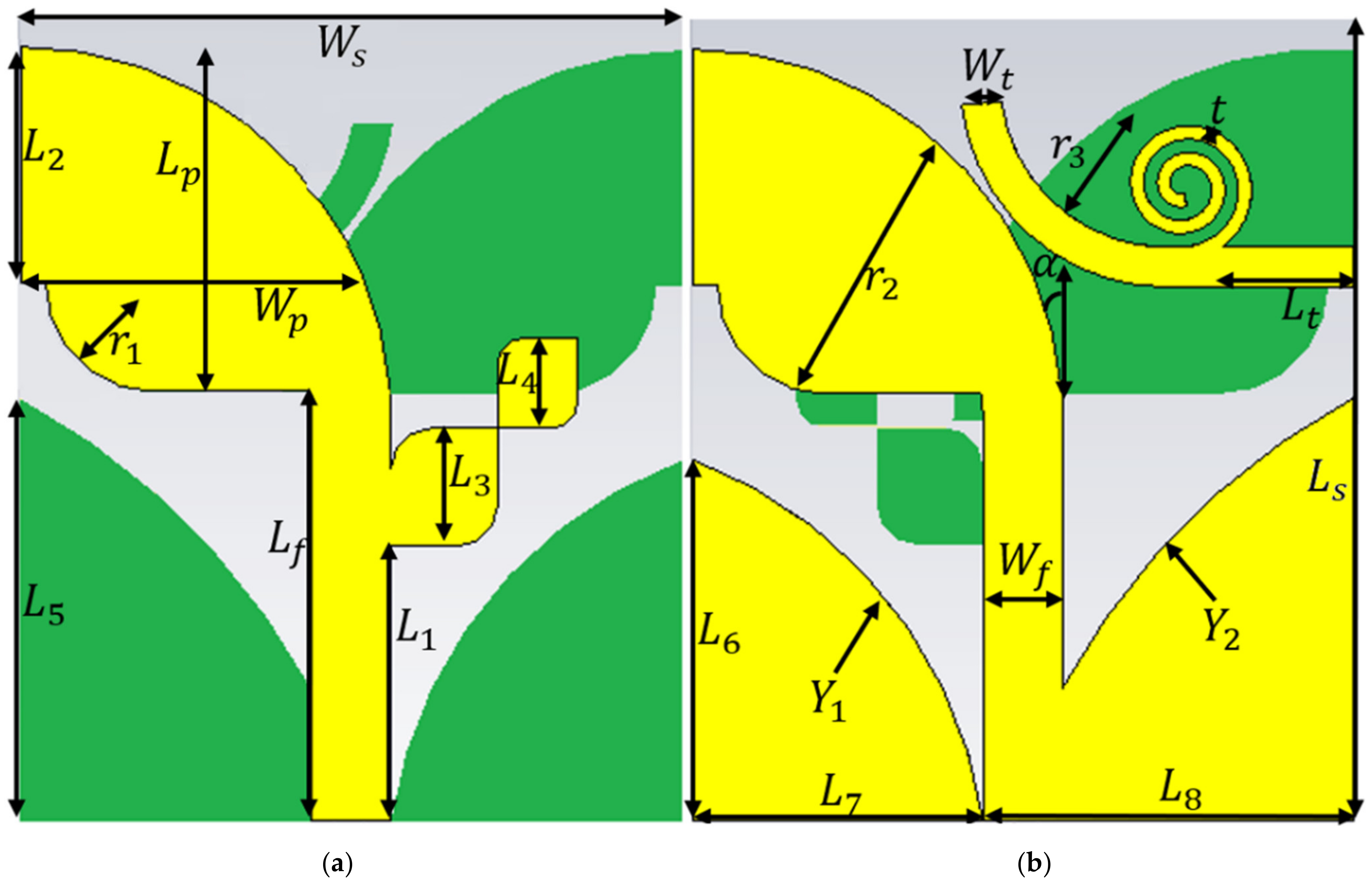
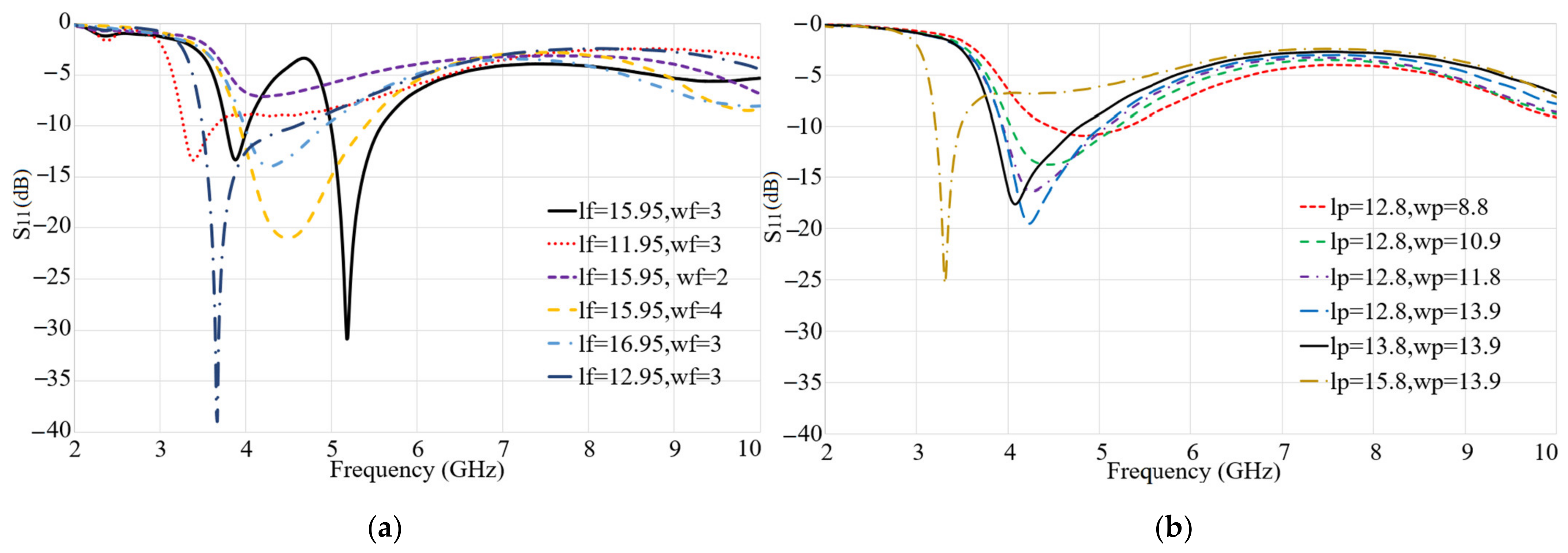
2.1. Antipodal Antenna and Spiral Patch Antenna Design Configuration
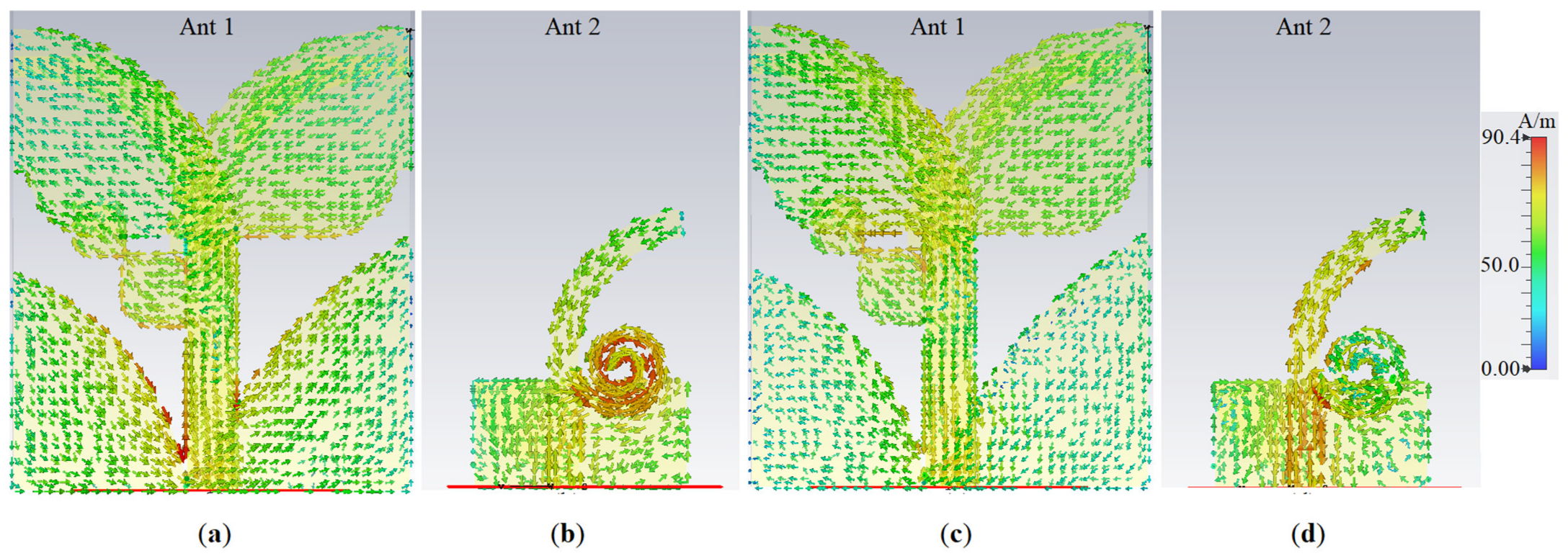
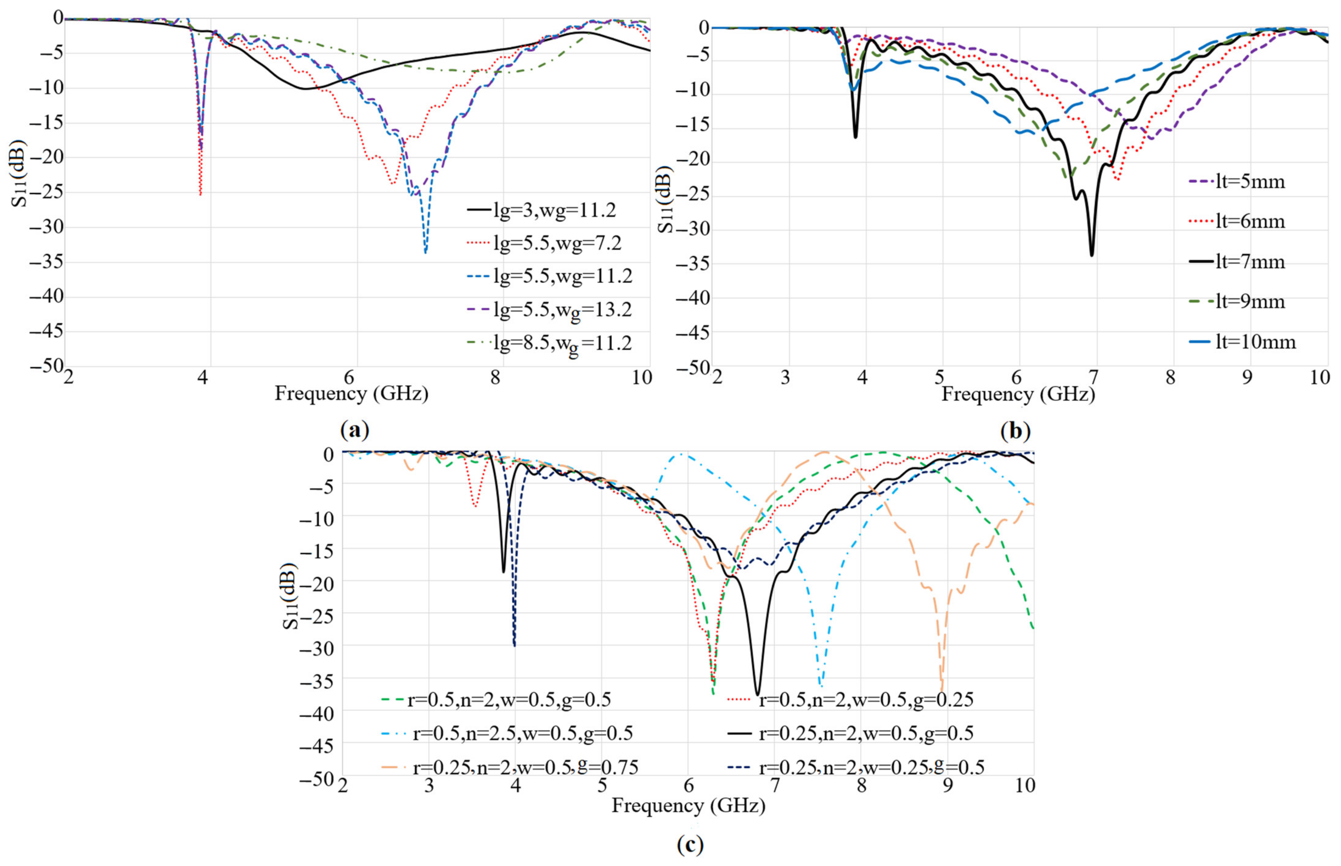
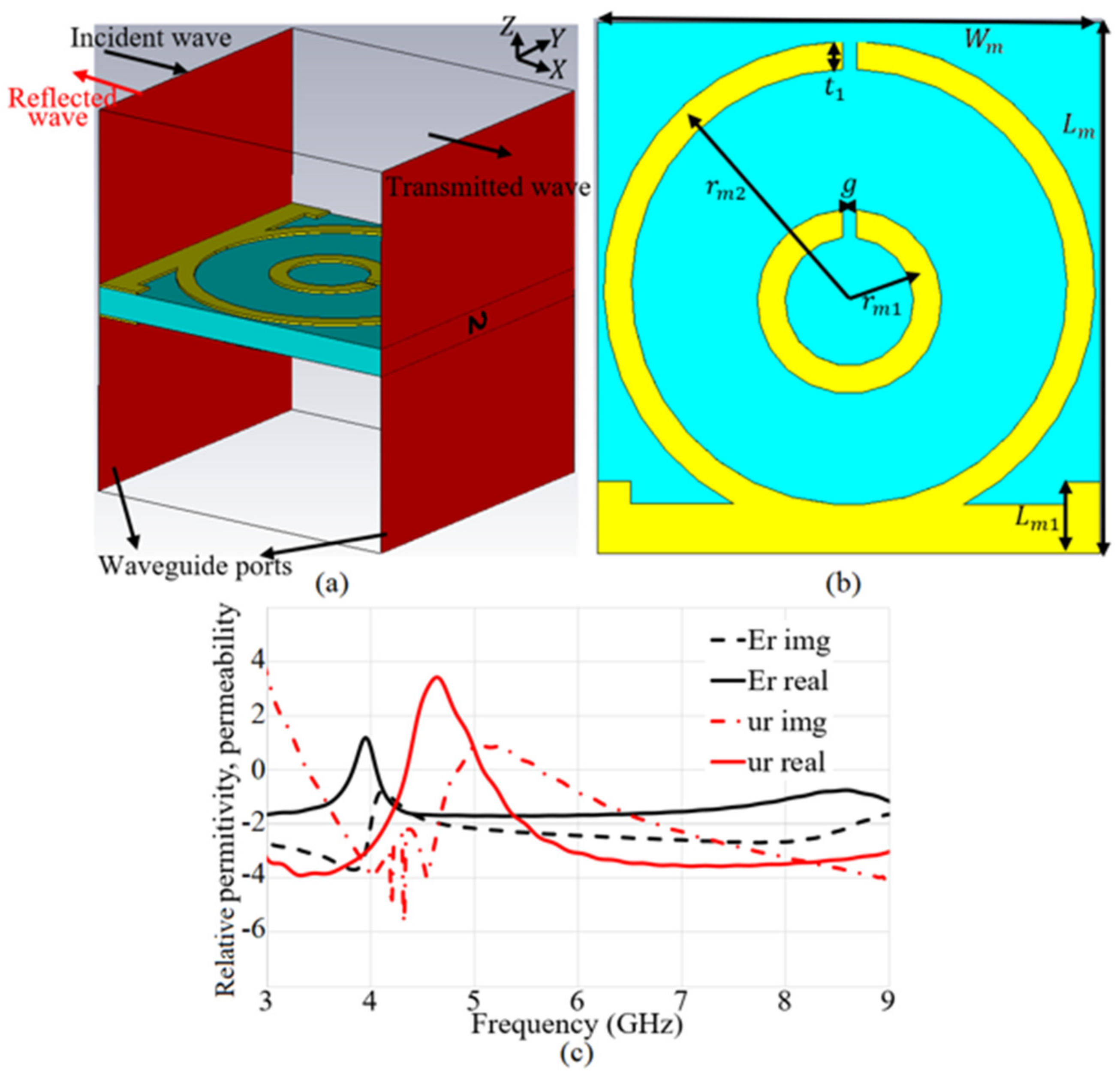
2.2. Single Element Metamaterial Antenna and the Array Configurations
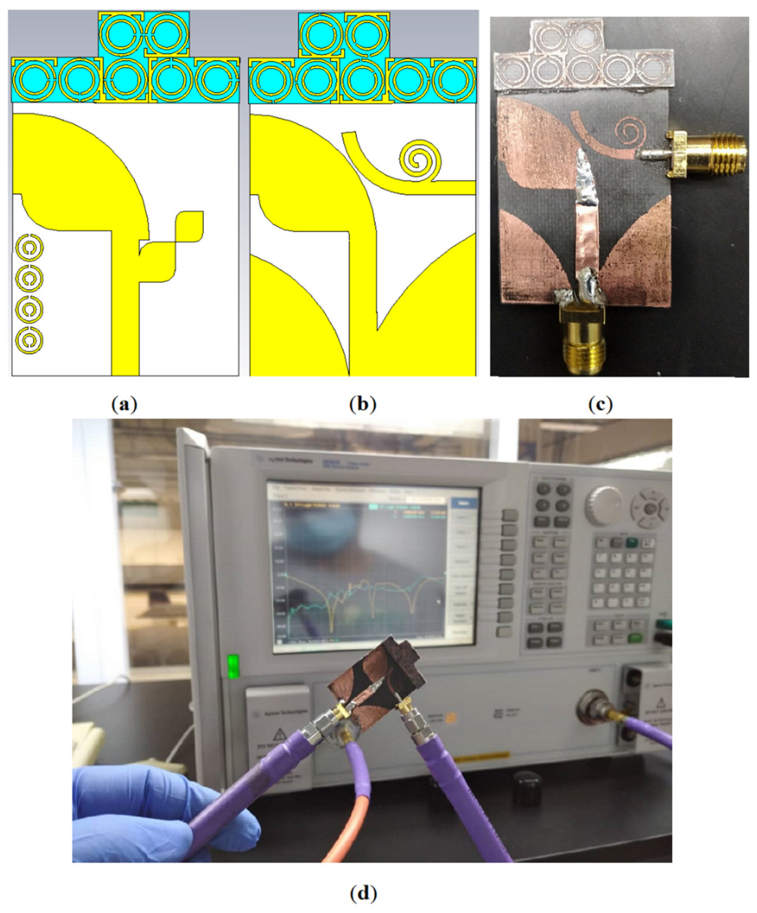
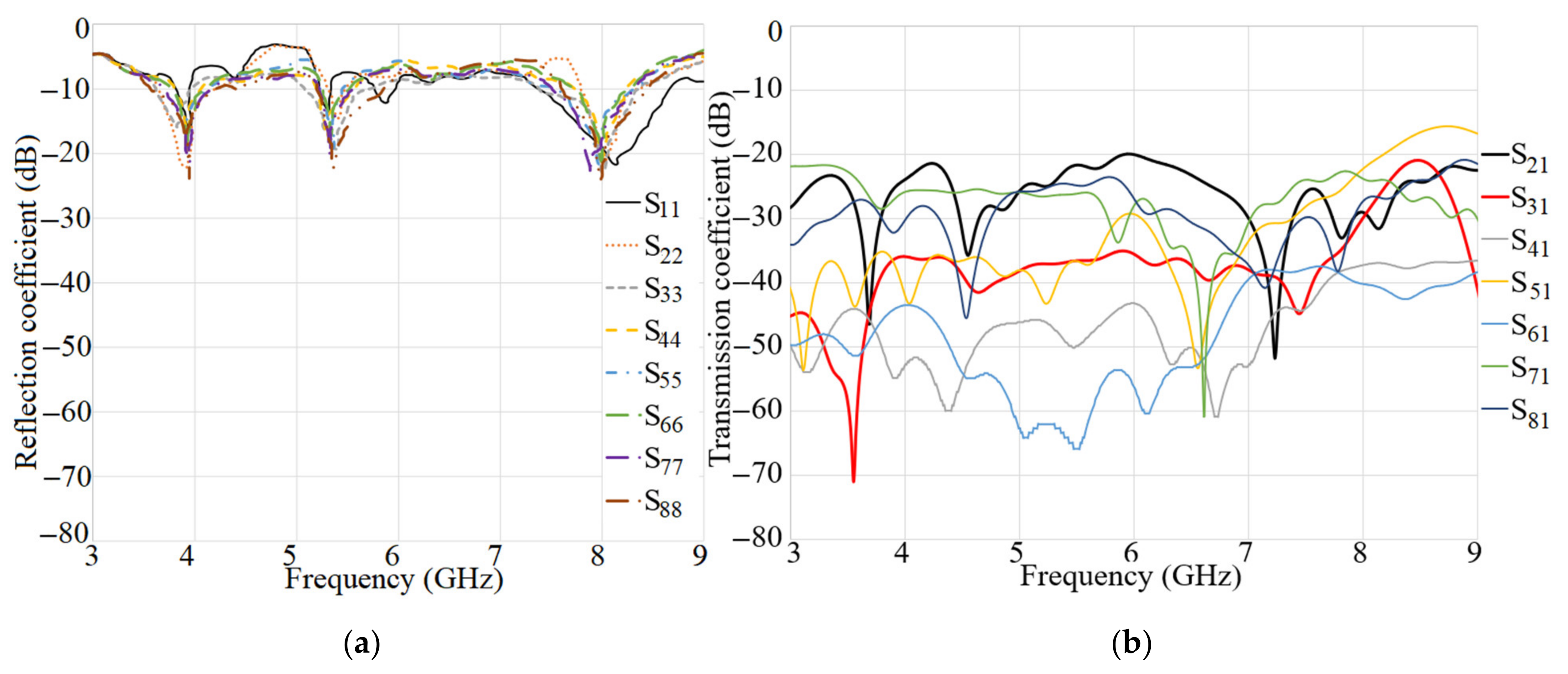
2.3. Design and Characterization of MIMO Antenna Integrated with MTM Structure
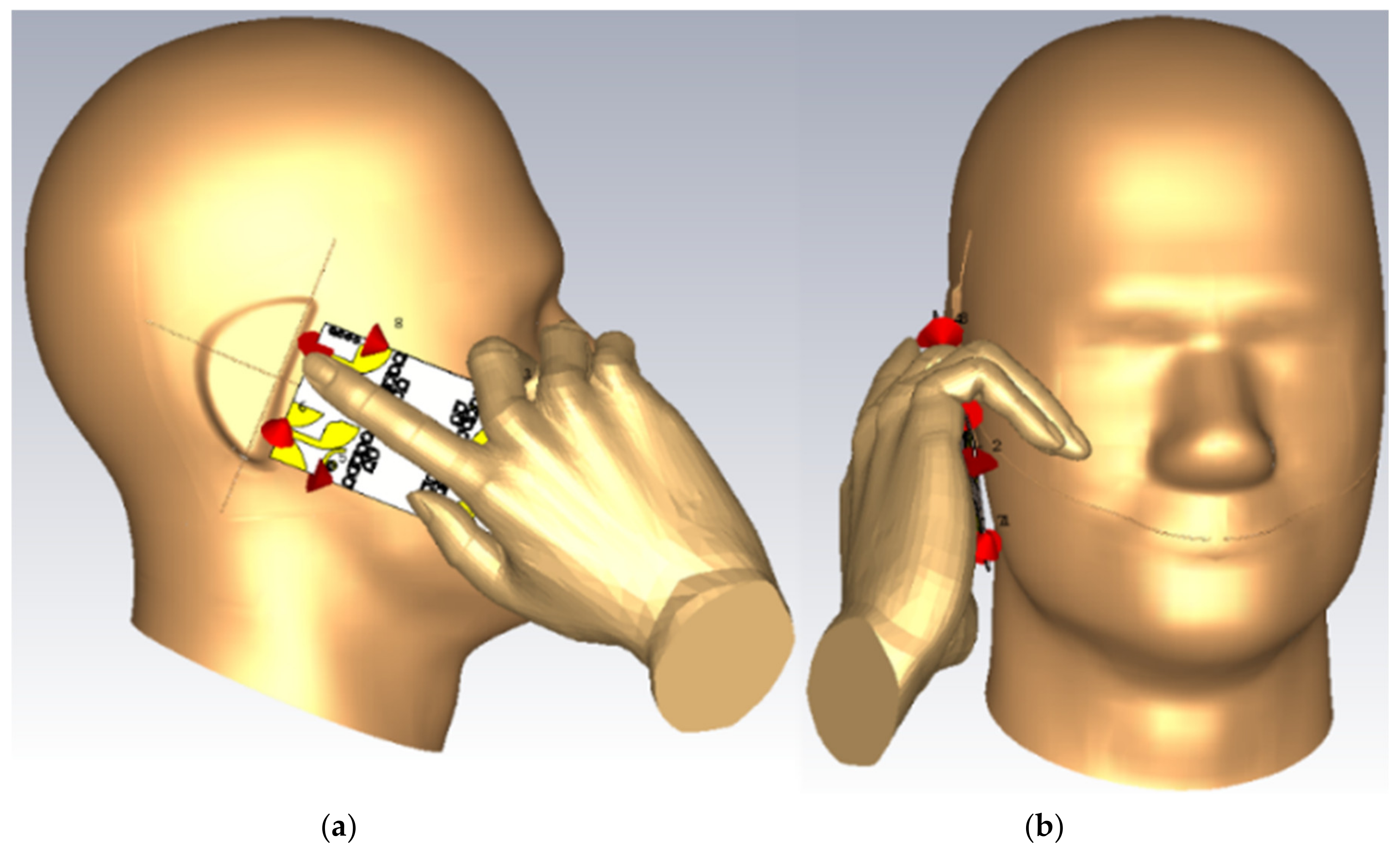
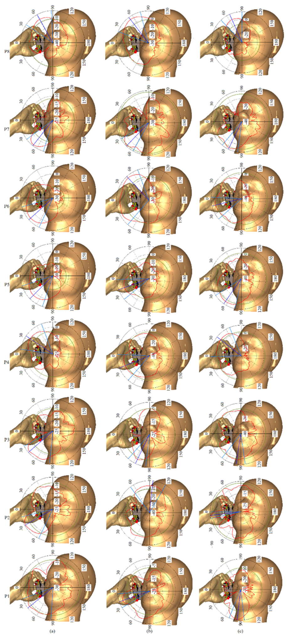
3. Proposed MIMO Antenna for Smartphones
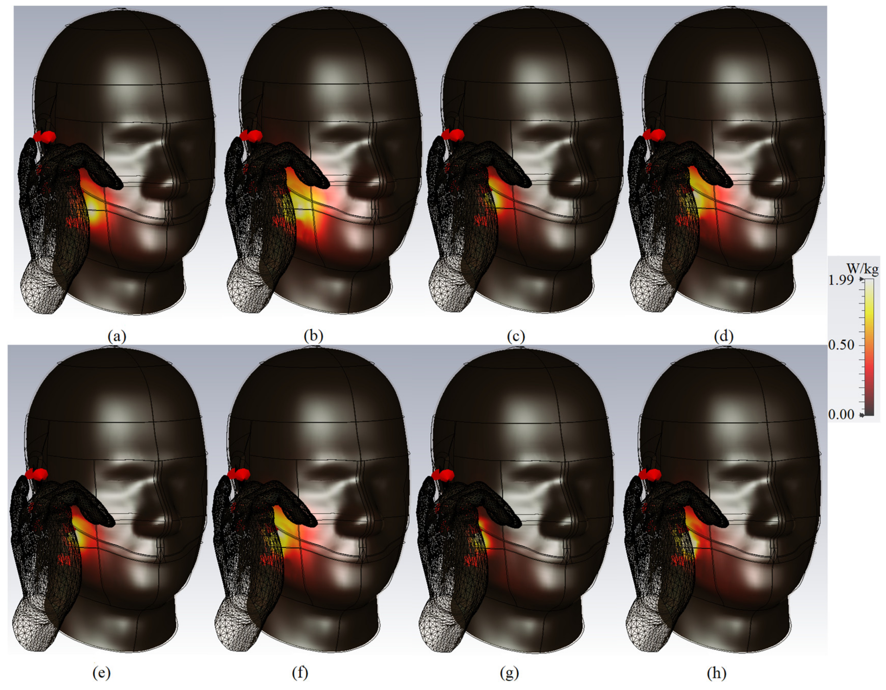
Specific Absorption Rate
4. Conclusions
Author Contributions
Funding
Acknowledgments
Conflicts of Interest
References
- Global Mobile Suppliers Association. A GSA Executive Report from Ericsson, “The Road to 5G: Drivers, Applications, Requirements and Technical Development”; Global Mobile Suppliers Association: Shenzhen, China, 2015. [Google Scholar]
- Sharony, J. Introduction to Wireless MIMO-Theory and Applications. Available online: https//ieee.li/pdf/viewgr-aphs/Introd (accessed on 15 November 2006).
- Shoaib, N.; Shoaib, S.; Khattak, R.Y.; Shoaib, I.; Chen, X.; Perwaiz, A. MIMO antennas for smart 5G devices. IEEE Access 2018, 6, 77014–77021. [Google Scholar] [CrossRef]
- Sultan, K.S.; Abdullah, H.H.; Abdallah, E.A.; El-Hennawy, H.S. Metasurface-based dual polarized MIMO Antenna for 5G smartphones using CMA. IEEE Access 2020, 8, 37250–37264. [Google Scholar] [CrossRef]
- Sarkar, D.; Srivastava, K.V. Compact four-element SRR-loaded dual-band MIMO antenna for WLAN/WiMAX/WiFi/4G-LTE and 5G applications. Electron. Lett. 2017, 53, 1623–1624. [Google Scholar] [CrossRef]
- Al Abbas, E.; Ikram, M.; Mobashsher, A.T.; Abbosh, A. MIMO antenna system for multi-band millimeter-wave 5G and wideband 4G mobile communications. IEEE Access 2019, 7, 181916–181923. [Google Scholar] [CrossRef]
- Ni, J.; Hong, J. Compact continuously tunable microstrip low-pass filter. IEEE Trans. Microw. Theory Tech. 2013, 61, 1793–1800. [Google Scholar] [CrossRef]
- Syeda, I.; Hussain, N.; Iqbal, A.; Rahman, M. Integrated LTE and millimeter-wave 5G MIMO antenna system for 4G/5G wireless terminals. Sensors 2020, 20, 3926. [Google Scholar]
- Uthansakul, P.; Assanuk, D.; Uthansakul, M. An optimal design of multiple antenna positions on mobile devices based on mutual coupling analysis. Int. J. Antennas Propag. 2011, 2011, 791697. [Google Scholar] [CrossRef] [Green Version]
- Chen, X.; Zhang, S.; Li, Q. A review of mutual coupling in MIMO systems. IEEE Access 2018, 6, 24706–24719. [Google Scholar] [CrossRef]
- Ban, Y.L.; Li, C.; Sim, C.Y.D.; Wu, G.; Wong, K.L. 4G/5G multiple antennas for future multi-mode smartphone applications. IEEE Access 2016, 4, 2981–2988. [Google Scholar] [CrossRef]
- Wong, K.L.; Chang, H.J. Hybrid dual-antenna for the 3.6-GHz LTE operation in the tablet computer. Microw. Opt. Technol. Lett. 2015, 57, 592–2598. [Google Scholar] [CrossRef]
- Lin, Y.; Chen, W.; Chen, C.; Liao, C.; Chuang, N.; Chen, H. High-gain MIMO dipole antennas with mechanical steerable main beam for 5G small cell. IEEE Antennas Wirel. Propag. Lett. 2019, 18, 1317–1321. [Google Scholar] [CrossRef]
- Wang, Z.; Du, Y.A. Wideband printed dual-antenna with three neutralization lines for mobile terminals. IEEE Trans. Antennas Propag. 2014, 62, 1495–1500. [Google Scholar] [CrossRef]
- Su, F.S.; Lee, S.W.; Chang, C.T. Printed MIMO-antenna system using neutralization-line technique for wireless USB-dongle applications. IEEE Trans. Antennas Propag. 2012, 60, 456–463. [Google Scholar] [CrossRef]
- Zhao, K.L.; Wu, L.A. Decoupling technique for four-element symmetric arrays with reactively loaded dummy elements. IEEE Trans. Antennas Propag. 2014, 62, 4416–4421. [Google Scholar] [CrossRef]
- Yeung, Y.E.; Wang, L.K. Mode-based beamforming arrays for miniaturized platforms. IEEE Trans. Microw. Theory Tech. 2009, 57, 45–52. [Google Scholar] [CrossRef]
- Wang, T.F.; Li, K.; Eibert, L. Comparison of compact monopole antenna arrays with eigenmode excitation and multiport conjugate matching. IEEE Trans. Antennas Propag. 2013, 61, 4054–4062. [Google Scholar] [CrossRef]
- Andersen, J.; Rasmussen, H. Decoupling and descattering networks for antennas. IEEE Trans. Antennas Propag. 1976, 24, 841–846. [Google Scholar] [CrossRef]
- Wei, R.; Li, K.; Wang, J.Y.; Xing, L.; Xu, Z.J. Mutual coupling reduction by novel fractal defected ground structure bandgap filter. IEEE Trans. Antennas Propag. 2016, 64, 4328–4335. [Google Scholar] [CrossRef]
- Mavridou, P.; Feresidis, M.; Gardner, A.P. Tunable double-layer EBG structures and application to antenna isolation. IEEE Trans. Antennas Propag. 2016, 64, 70–79. [Google Scholar] [CrossRef]
- Pan, B.C.; Tang, W.X.; Qi, M.Q.; Ma, H.F.; Tao, Z.; Cui, T.J. Reduction of the spatially mutual coupling between dual-polarized patch antennas using coupled metamaterial slabs. Sci. Rep. 2016, 6, 30288. [Google Scholar] [CrossRef] [Green Version]
- Wang, Z.; Zhao, L.; Cai, Y.; Zheng, S.; Yin, Y. A Meta-Surface Antenna Array Decoupling (MAAD) method for mutual coupling reduction in a MIMO antenna system. IEEE Access 2018, 8, 61797–61805. [Google Scholar] [CrossRef]
- Park, J.; Ko, J.; Kwon, H.; Kang, B.; Park, B.; Kim, D. A tilted combined beam antenna for 5G communications using a 28-GHz band. IEEE Antennas Wirel. Propag. Lett. 2016, 15, 1685–1688. [Google Scholar] [CrossRef]
- Ta, S.X.; Choo, H.; Park, I. Broadband printed-dipole antenna and its arrays for 5G applications. IEEE Antennas Wirel. Propag. Lett. 2017, 16, 2183–2186. [Google Scholar] [CrossRef]
- Mak, K.M.; Lai, H.W.; Luk, K.M.; Chan, C.H. Circularly polarized patch antenna for future 5G mobile phones. IEEE Access 2014, 2, 1521–1529. [Google Scholar]
- Juan, Y.; Che, W.; Yang, W.; Chen, Z.N. Compact pattern reconfigurable monopole antenna using parasitic strips. IEEE Antennas Wirel. Propag. Lett. 2017, 16, 557–560. [Google Scholar] [CrossRef]
- Farzami, F.; Khaledian, S.; Smida, B.; Erricolo, D. Pattern reconfigurable printed dipole antenna using loaded parasitic elements. IEEE Antennas Wirel. Propag. Lett. 2017, 16, 1151–1154. [Google Scholar] [CrossRef]
- Wen, D.L.; Zheng, D.Z.; Chu, Q.X. A dual-polarized antenna using four folded dipole and its array for base stations. IEEE Trans. Antennas Propag. 2016, 64, 5536–5542. [Google Scholar] [CrossRef]
- Bao, Z.; Nie, Z.; Zong, A. A novel broadband dual-polarization antenna utilizing strong mutual coupling. IEEE Trans. Antennas Propag. 2014, 62, 450–454. [Google Scholar] [CrossRef]
- Weller, T.M.; Nassar, I.T. A novel method for improving antipodal Vivaldi antenna performance. IEEE Trans. Antennas Propag. 2015, 63, 3321–3324. [Google Scholar]
- De Oliveira, A.M.; Perotoni, M.B.; Kofuji, S.T.; Justo, J.F. A palm tree antipodal Vivaldi antenna with exponential slot edge for improved radiation pattern. IEEE Antennas Wirel. Propag. Lett. 2015, 14, 1334–1337. [Google Scholar] [CrossRef]
- Amiri, M.; Tofigh, F.; Yazdi, A.M.; Abolhasan, M. Exponential antipodal Vivaldi antenna with exponential dielectric lens. IEEE Antennas Wirel. Propag. Lett. 2017, 16, 1792–1795. [Google Scholar] [CrossRef]
- Gazit, E. Improved design of the Vivaldi antenna. IEE Proc. H (Microw. Antennas Propag.) 1988, 135, 89–92. [Google Scholar] [CrossRef]
- Ostadrahimi, M.; Noghanian, S.; Shafai, L.; Zakaria, A.; Kaye, C.; LoVetri, J. Investigating double-layer Vivaldi antenna for fixed array field measurement. Int. J. Ultra Wideband Commun. Syst. Spec. Issue Appl. UWB Biomed. 2010, 1, 282–290. [Google Scholar] [CrossRef] [Green Version]
- Ostadrahimi, M.; Mojabi, P.; Noghanian, S.; Shafai, L.; Pistorius, S.; LoVetri, J. A novel microwave tomography system based on the scattering probe technique. IEEE Trans. Instrum. Measur. 2012, 61, 379–390. [Google Scholar] [CrossRef]
- Wang, Y.; Yu, Z. A novel symmetric double-slot structure for antipodal Vivaldi antenna to lower cross-polarization level. IEEE Trans. Antennas Propag. 2017, 65, 5599–5604. [Google Scholar] [CrossRef]
- Moosazadeh, M.; Kharkovsky, S. A compact high-gain and front-to-back ratio elliptically tapered antipodal Vivaldi antenna with trapezoid-shaped dielectric lens. IEEE Antennas Wirel. Propag. Lett. 2016, 15, 552–555. [Google Scholar] [CrossRef]
- Chen, L.; Lei, Z.; Yang, R.; Fan, J.; Shi, X. A broadband artificial material for gain enhancement of antipodal tapered slot antenna. IEEE Trans. Antennas Propag. 2015, 63, 395–400. [Google Scholar] [CrossRef]
- Zhang, J.; Zhang, X.; Xiao, S. Antipodal Vivaldi antenna to detect uhf signals that leaked out of the joint of a transformer. Int. J. Antennas Propag. 2017, 2017, 9627649. [Google Scholar] [CrossRef] [Green Version]
- Garg, R.; Bhartia, P.; Bahl, I.; Ittipiboon, A. Microstrip Antenna Design Handbook; Artech House INC: Norwood, MA, USA, 2001. [Google Scholar]
- Eichenberger, J.; Yetisir, E.; Ghalichechi, N. High-Gain Antipodal Vivaldi Antenna with Pseudoelement and Notched Tapered Slot Operating at (2.5 to 57) GHz. IEEE Trans. Antennas Propag. 2019, 67, 4357–4366. [Google Scholar] [CrossRef]
- Islam, M.M.; Islam, M.T.; Samsuzzaman, M.; Faruque, M.R. Compact metamaterial antenna for UWB applications. Electron. Lett. 2015, 51, 1222–1224. [Google Scholar] [CrossRef]
- Smith, S.; Padilla, D.R.; Vier, W.J.; Nemat-Nasser, D.; Schultz, S.C. Composite medium with simultaneously negative permeability and permittivity. Phys. Rev. Lett. 2000, 84, 4184. [Google Scholar] [CrossRef] [PubMed] [Green Version]
- Dong, T.Y.; Toyao, H.; Itoh, T. Design and characterization of miniaturized patch antennas loaded with complementary split-ring resonators. IEEE Trans. Antennas Propag. 2012, 60, 772–785. [Google Scholar] [CrossRef]
- Mousavi Razi, Z.; Rezaei, P. Fabry cavity antenna based on capacitive loaded strips superstrate for X-Band satellite communication. ARS J. 2013, 2, 26–30. [Google Scholar]
- Rothwell, E.J.; Frasch, J.L.; Ellison, S.M.; Chahal, P.; Ouedraogo, R.O. Analysis of the Nicolson-Ross-Weir method for characterizing the electromagnetic properties of engineered materials. Prog. Electromagn. Res. 2016, 157, 31–47. [Google Scholar] [CrossRef] [Green Version]
- Gao, P.; He, S.; Wei, X.; Xu, Z.; Wang, N.; Zheng, Y. Compact printed UWB diversity slot antenna with 5.5-GHz band-notched characteristics. IEEE Antennas Wirel. Propag. Lett. 2014, 13, 376–379. [Google Scholar] [CrossRef]
- Tripathi, S.; Mohan, A.; Yadav, S. A compact Koch fractal UWB MIMO antenna with WLAN band-rejection. IEEE Antennas Wirel. Propag. Lett. 2015, 14, 1565–1568. [Google Scholar] [CrossRef]
- Li, Y.; Sim, C.-Y.-D.; Luo, Y.; Yang, G. 12-port 5G massive MIMO antenna array in sub-6GHz mobile handset for LTE bands 42/43/46 applications. IEEE Access 2018, 6, 344–354. [Google Scholar] [CrossRef]
- Sultan, K.S.H.; Abdullah, H.; Abdallah, E.A.; Hashish, E.A. Low- SAR, miniaturized printed antenna for mobile, ISM, and WLAN services. IEEE Antennas Wirel. Propag. Lett. 2013, 12, 1106–1109. [Google Scholar] [CrossRef]
- Abdullah, H.H.; Sultan, K.S. Multiband compact low SAR mobile handheld antenna. Prog. Electromagn. Res. Lett. 2014, 49, 65–71. [Google Scholar] [CrossRef] [Green Version]
- Sultan, K.S.; Abdullah, H.H.; Abdullah, E.A. Comprehensive study of printed antenna with the handset modeling. Microw. Opt. Technol. Lett. 2016, 58, 974–980. [Google Scholar] [CrossRef]
- IEEE. IEEE Standard for Safety Levels with Respect to Human Exposure to Electric, Magnetic, and Electromagnetic Fields, 0 Hz to 300 GHz; IEEE Access: Bucharest, Romania, 2019. [Google Scholar] [CrossRef]
- Si, L.; Jiang, H.; Lv, X.; Ding, J. Broadband extremely close-spaced 5G MIMO antenna with mutual coupling reduction using metamaterial-inspired superstrate. Opt. Express 2019, 27, 3472–3482. [Google Scholar] [CrossRef] [PubMed]
- Al-Tarifi, M.A.; Sharawi, M.S.; Shamim, A. Massive MIMO antenna system for 5G base stations with directive ports and switched beam steering capabilities. IET Microw. Antennas Propag. 2018, 12, 1709–1718. [Google Scholar] [CrossRef] [Green Version]
- Wu, C.; Lu, C.; Cao, W. Wideband dual polarization slot antenna with high isolation by using microstrip line Balun feed. IEEE Antennas Wirel. Propag. Lett. 2017, 16, 1759–1762. [Google Scholar] [CrossRef]
- Wong, K.; Chang, H.; Chen, J.; Wang, K. Three wideband monopolar patch antennas in a Y-shape structure for 5G multi-input-multi-output access points. IEEE Antennas Wirel. Propag. Lett. 2020, 19, 393–397. [Google Scholar] [CrossRef]
- Chattha, H.T. 4-Port 2-element MIMO antenna for 5G portable applications. IEEE Access 2019, 7, 96516–96520. [Google Scholar] [CrossRef]
- Parchin, N.O.; Al-Yasir, Y.I.A.; Ali, A.H.; Elfergani, I.; Noras, J.M.; Rodriguez, J.; Abdalhameed, R.A. Eight-element dual-polarized MIMO slot antenna system for 5G smartphone applications. IEEE Access 2020, 7, 15612–15622. [Google Scholar] [CrossRef]
- Guo, J.; Cui, L.; Li, C.; Sun, B. Side-edge frame printed eight-port dual-band antenna array for 5G smartphone applications. IEEE Trans. Antennas Propag. 2018, 66, 7412–7417. [Google Scholar] [CrossRef]
- Li, M.; Ban, Y.; Xu, Z.; Wu, G.; Sim, C.Y.D.; Kang, K.; Yu, Z. 8-port orthogonally dual-polarized antenna array for 5G smartphone applications. IEEE Trans. Antennas Propag. 2016, 64, 3820–3830. [Google Scholar] [CrossRef]
- Li, Y.; Sim, C.; Luo, Y.; Yang, G. Multi-Band 10-antenna array for Sub-6 GHz MIMO applications in 5G smartphones. IEEE Access 2018, 6, 28041–28053. [Google Scholar] [CrossRef]


| Parameters | Dimensions (mm) | Parameters | Dimensions (mm) |
|---|---|---|---|
| 30 | 13.9 | ||
| 15.95 | 12.8 | ||
| 7 | 13.9 | ||
| 10.3 | 24.8 | ||
| 8.85 | 3 | ||
| 4.4 | 1.5 | ||
| 3.4 | 4.25 | ||
| 15.8 | 12 | ||
| 13.5 | 6.25 | ||
| 10.9 | t | 0.5 |
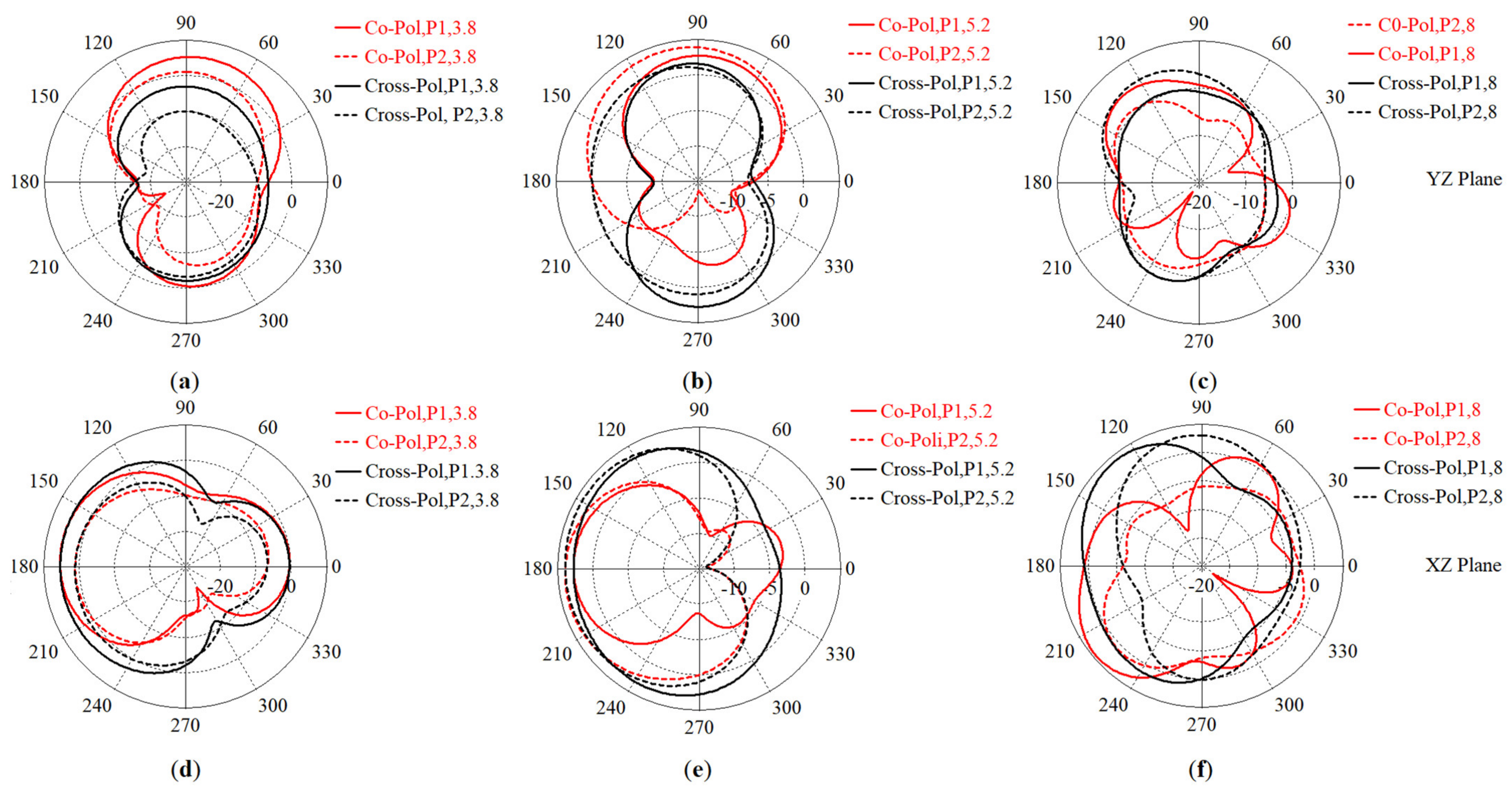
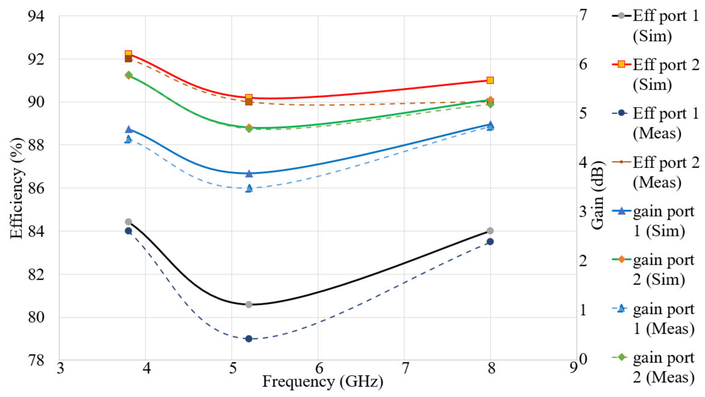
| Gain (dBi) Port 1 Sim/Meas | Gain (dBi) Port 2 Sim/Meas | Eff (%) Port 1 Sim/Meas | Eff (%) Port 2 Sim/Meas | |
|---|---|---|---|---|
| 3.8 | 4.70/4.50 | 5.78/5.80 | 84.42/84.00 | 92.00/91.00 |
| 5.2 | 3.80/3.50 | 4.73/4.70 | 80.58/79.00 | 90.19/89.50 |
| 8.0 | 4.80/4.75 | 5.29/5.20 | 84.00/83.50 | 91.00/90.00 |
| Parameters | Dimensions (mm) |
|---|---|
| 5 | |
| 1 | |
| 5 | |
| 1.4 | |
| 2.2 | |
| 0.35 | |
| g | 0.25 |
| Parameters | ||
|---|---|---|
| Operating BW (GHz) | 0–3.8, 4.1–9.0 | 0–4.2, 5.35–9.0 |
| Port 1/fr | 3.8 GHz | 5.2 GHz | 5.4 GHz | 8 GHz |
|---|---|---|---|---|
| SAR 1g | 0.526 | 0.723 | 0.990 | 1.091 |
| SAR 10 g | 0.391 | 1.121 | 1.540 | 1.991 |
| Reference Number | Dimensions (mm) | Max Isolation (dB) | Max Gain (dBi) | Band (GHz) | Efficiency (%) | Max ECC |
|---|---|---|---|---|---|---|
| [8] | 75 × 25 | 20 | 5.3 | 5.29–6.12, 26.0–29.5 | 73 | 0.05 |
| [55] | 58 × 40 | 15 | 6.59 | 4.20–5.25 | - | - |
| [56] | 74 × 74 | 14.9 | 9.41 | 3.45–3.55 | 64 | 0.1192 |
| [57] | 150 × 150 | 35 | 8.5 | 2.40–4.26 | - | - |
| [58] | 45.8 × 52.9 | <20 | - | 3.3–4.2 | 88 | <0.1 |
| [59] | 50 × 100 | 25 | >3 | 2.7–3.6 | 92 | <0.009 |
| Proposed | 24.8 × 40 | >22 | 6.75 | 3.30–4.45, 4.7–5.3, 7.7–8.25 | 91 | <0.089 |
| Reference Number | Phone Board (mm2) | MIMO Order | Max Gain (dBi) | Max Isolation (dB) | Efficiency (%) | Max ECC |
|---|---|---|---|---|---|---|
| [4] | 100 × 60 | 8 | 11 | 40 | 90 | 0.001 |
| [6] | 136 × 68 | 4 | 7.2 | <60 | - | - |
| [60] | 75 × 150 | 8 | 4 | 25 | >70 | - |
| [61] | 150 × 75 | 8 | 4 | 11.5 | 85 | <0.08 |
| [62] | 68 × 136 | 8 | - | >18 | ~60 | <0.15 |
| [63] | 150 × 80 | 10 | - | >11 | <82 | <0.2 |
| Proposed | 100 × 60 | 8 | 13.5 | <40 | 94 | 0.009 |
Publisher’s Note: MDPI stays neutral with regard to jurisdictional claims in published maps and institutional affiliations. |
© 2021 by the authors. Licensee MDPI, Basel, Switzerland. This article is an open access article distributed under the terms and conditions of the Creative Commons Attribution (CC BY) license (http://creativecommons.org/licenses/by/4.0/).
Share and Cite
Saeidi, T.; Ismail, I.; Noghanian, S.; Alhawari, A.R.H.; Abbasi, Q.H.; Imran, M.A.; Zeain, M.Y.; Ali, S.M. High Gain Triple-Band Metamaterial-Based Antipodal Vivaldi MIMO Antenna for 5G Communications. Micromachines 2021, 12, 250. https://doi.org/10.3390/mi12030250
Saeidi T, Ismail I, Noghanian S, Alhawari ARH, Abbasi QH, Imran MA, Zeain MY, Ali SM. High Gain Triple-Band Metamaterial-Based Antipodal Vivaldi MIMO Antenna for 5G Communications. Micromachines. 2021; 12(3):250. https://doi.org/10.3390/mi12030250
Chicago/Turabian StyleSaeidi, Tale, Idris Ismail, Sima Noghanian, Adam R. H. Alhawari, Qammer H. Abbasi, Muhammad Ali Imran, M. Y. Zeain, and Shahid M. Ali. 2021. "High Gain Triple-Band Metamaterial-Based Antipodal Vivaldi MIMO Antenna for 5G Communications" Micromachines 12, no. 3: 250. https://doi.org/10.3390/mi12030250