Diffusion Bonding of 9Cr Martensitic/Ferritic Heat-Resistant Steels with an Electrodeposited Ni Interlayer

State Key Lab of Hydraulic Engineering Simulation and Safety, School of Materials Science & Engineering, Tianjin University, Tianjin 300354, China
*
Author to whom correspondence should be addressed.
Metals 2018, 8(12), 1012; https://doi.org/10.3390/met8121012
Submission received: 3 November 2018
/
Revised: 21 November 2018
/
Accepted: 30 November 2018
/
Published: 2 December 2018
Abstract
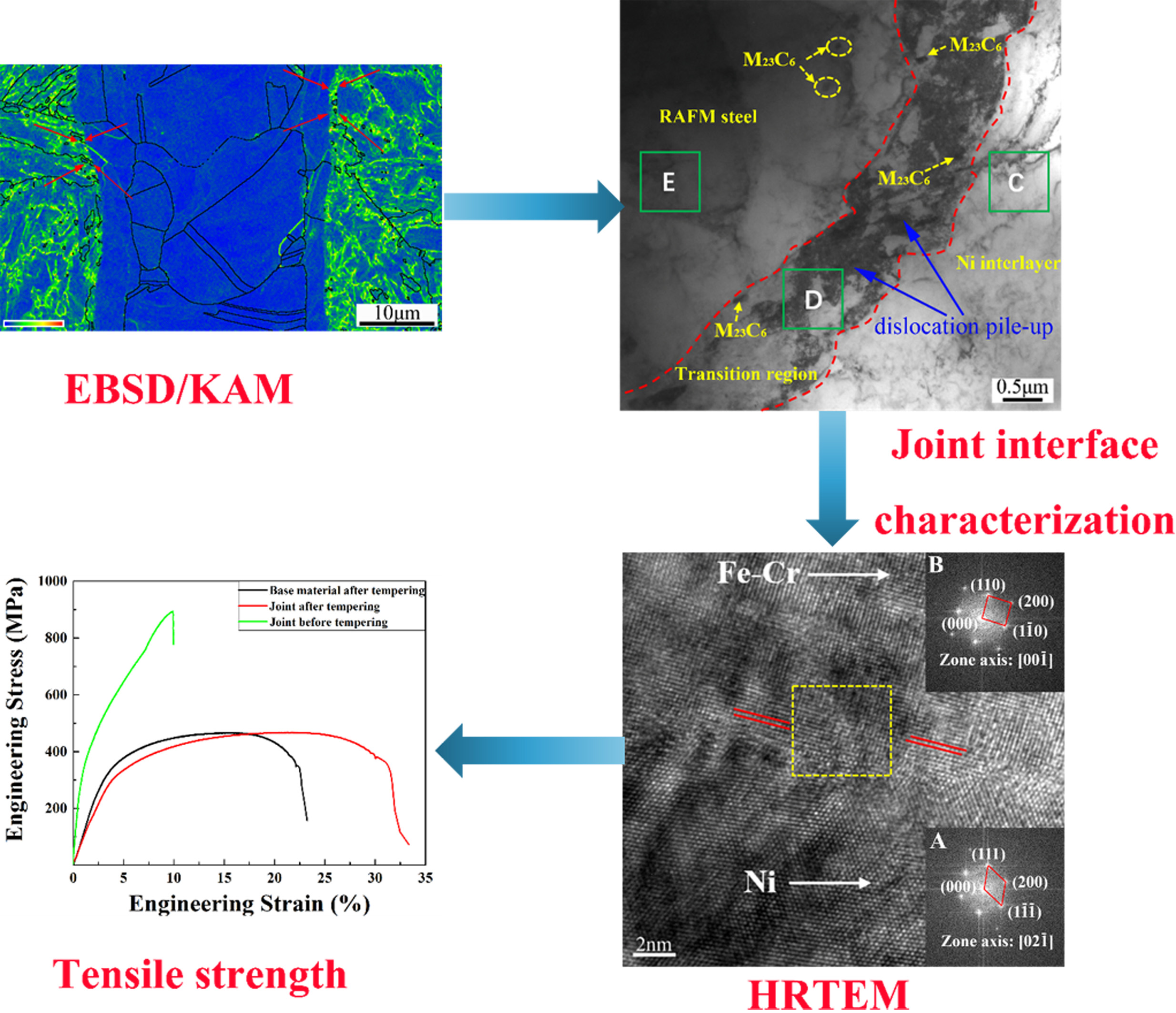
:In this paper, diffusion bonding was adopted to join 9Cr martensitic/ferritic heat-resistant steels using an electrodeposited Ni interlayer with a thickness of 40 μm. In addition, the effect of tempering treatment after diffusion bonding on the microstructure evolution and mechanical properties of the bonding joints was investigated. It was found that a transition region with face-centered cubic (FCC) structure was formed between the steel and Ni interlayer. The transition region was the solid solution of (γFe,Ni) rich in Ni component, being related to martensite in the base metal by the Kurdjumov–Sachs (K-S) orientation relationship. No intermetallic compounds were detected at the bonding joints before and after tempering treatment. After tempering treatment, the transition region had higher dislocation density than other regions, due to the higher pinning effect of solute atoms acting on the dislocation than that of the matrix. Tensile tests indicated that tempering treatment improved the mechanical properties of the joint, since the samples after tempering treatment fractured in the base metal, whereas the specimens without tempering treatment fractured at the joint interface.

1. Introduction
Nuclear energy has been considered preferentially to meet energy shortages and environmental stewardship challenges in the future owing to its abundance, environmental compatibility, cost-effective operation, and zero carbon emissions [1,2]. The 9Cr martensitic/ferritic heat-resistant steel has been selected as the primary candidate structural material for blanket components in nuclear reactors due to its outstanding comprehensive performance, such as low thermal expansion coefficient, high thermal conductivity, and favorable radiation swelling resistance in a high-radiation-flux environment [3,4,5,6].
The welding techniques are critical to the practical application of 9Cr martensitic/ferritic heat-resistant steel in nuclear reactors. In order to join this steel to the same steel or other materials, a variety of fusion welding technologies have been employed, including electron beam (EB) welding [7,8], laser welding [8], hybrid welding [8,9], and tungsten inert gas (TIG) welding [10,11]. Fusion welding will change the microstructure of the matrix adjacent to the weld bead. Traditional fusion welding usually involves the microstructure gradients in the heat-affected zones of welds, which include overtempered regions, intercritical regions, fine-grain regions, and coarse-grain regions [12]. The existence of these regions can decrease the joint strength and toughness. However, diffusion bonding as a solid-state welding technique has nearly no phase transformation or microstructure change after bonding [13]. Therefore, with diffusion bonding it is feasible to produce joints of near base material quality for complex structures. Zhou et al. [14] studied the uniaxial diffusion bonding of China low-activation martensitic (CLAM) steels and attained good interface connectivity with optimal mechanical properties. However, the diffusion rate of elements in solid is very slow and the plastic deformation of solid materials is difficult during diffusion bonding, so that higher bonding temperature and pressure and more time are required to eliminate interface holes and attain reliable joints, but increasing these parameters will cause appreciable macroscopic deformation and low productivity [15]. Nevertheless, the bonding temperature, time, and pressure during the diffusion bonding process can be reduced by using the interlayer; meanwhile, it can also improve the joint qualities. In order to improve the joint qualities and reduce the bonding parameters, Reuven et al. [16,17,18] did a lot of work to join 316L stainless steels by diffusion bonding using electroless nickel plating as interlayer. Tiwari et al. [19] studied the effect of nickel nanoparticle (NiNP) interlayer application to diffusion bonding of stainless steel. Transient liquid phase bonding with Ni-based amorphous foil as interlayer was adopted to join CLAM/CLAM steels; however, the combined effects of the alloying elements in the amorphous foil and the produced abundant boundaries in austenite transformation could result in a fine-grain region adjacent to the interlayer, similar to the case in fusion welding [20]. Ni is always used as interlayer for diffusion bonding, as Ni layer has excellent plasticity. Meanwhile, Ni layer can form continuous solid solutions with iron at high temperature, but no intermetallic compounds are formed in the Ni/steel diffusion couple [21,22,23].
In this work, the electrodeposited nickel layer is considered as a constructive intermediate material to join 9Cr martensitic/ferritic heat-resistant steels because of its remarkable adhesion to steel substrates with arbitrary shape. This study was aimed at exploring the interfacial microstructure evolution and mechanical properties using electrodeposited Ni as the interlayer metal by the diffusion bonding method. Furthermore, a tempering treatment was applied to promote interface bonding at the joints. The effect of tempering treatment on the possible microstructure evolution, especially adjacent to the joint interface, and the mechanical properties were also evaluated.
2. Material and Methods
The chemical composition of the 9Cr martensitic/ferritic heat-resistant steels used in this study is listed in Table 1. Prior to diffusion bonding, martensitic/ferritic steel after rolling was usually normalized at 1050 °C for 30 min followed by air cooling to room temperature, then tempered at 750 °C for 90 min, followed by air cooling to room temperature. Nominal dimensions of the specimens were all cut into a cylindrical shape with a size of 10 mm diameter × 10 mm length. The joint surface of the martensitic/ferritic steels was cleaned up and sanded flat with a series of SiC sandpaper from 240 to 1500 grit, and then polished. An ultrasonic cleaning process with alcohol for 10 min was used after grinding and polishing, followed by drying. Pure Ni coating, selected as the intermediate material, was coated on the surface of the martensitic/ferritic steel by electroplating. Prior to deposition of the Ni layer, the substrates were sequentially alkaline washed in 10% sodium hydroxide solution followed by cleaning with alcohol, then acid activated in 5% dilute sulfuric acid solution and rinsed with alcohol, followed by drying. The appropriate bath formula and deposition conditions of electrodeposited Ni layer are given in Table 2. The electrodeposition process was performed by SMD-60P pulse plating power supply under constant voltage mode and a current density of 3 A/dm2 was applied for 60 min. The thickness of the electrodeposited Ni layer was about 40 μm, measured by means of metallographic method and vernier caliper. Prior to diffusion bonding, a pair of specimens, one with an electrodeposited Ni layer and the other without, was assembled and encapsulated in the capsule of a diffusion bonding oven. The diffusion bonding process used high vacuum so that the capsule was outgassed to 1.0 × 10⁻³ Pa. The Gleeble 3500 (DSI, St. Paul, MN, USA) was used to perform the diffusion bonding process. After that, the diffusion bonding process was conducted in vacuum at 1050 °C for 60 min and the uniaxial pressure was 20 MPa; the heating rate was 4 °C/min during the bonding process. Finally, the samples were moved into air and cooled to room temperature. The diffusion bonding scheme for 9Cr martensitic/ferritic heat-resistant steels is given in Figure 1a. Then, in order to study the effect of tempering treatment on the mechanical properties of diffusion bonding, tempering treatment was conducted at 750 °C for 90 min by an SX-G03163 chamber electric furnace (ZHONGHUAN Experiment Electric Furnace Co., Ltd, Tianjin, China), followed by cooling in air to room temperature, as shown in Figure 1a.
The microstructures of bonded joints before and after tempering treatment were characterized by optical microscopy (OM, Leica DMI 8, Leica, Solms, Germany), scanning electron microscopy (SEM, SU1510, Hitachi, Tokyo, Japan), and transmission electron microscopy (TEM, JEM-2100f, JEOL, Akishima, Tokyo, Japan). The distribution of various elements across the joint region was examined by energy dispersive X-ray spectroscopy (EDS, EDAX, Mahwah, NJ, USA). For optical microscopy characterization, the samples were ground and polished, then etched by a mixed solution of 5% nitric acid, 2% hydrofluoric acid, and 93% water. In addition, the TEM specimens were prepared by the ion-beam thinning method. The tensile specimen had a gauge length of 4 mm, as shown in Figure 1b. A special clamp was used to mount the tensile samples on the Instron 8871, as shown in Figure 1c. Tensile tests were carried out on the Instron 8871 (Instron, Boston, MA, USA) at room temperature with a nominal strain rate of 10−3 s−1 to evaluate the reliability of joints. Two groups of samples prepared with the same bonding parameters were tested separately, and each group included 3 samples. For the electron back-scattered diffraction (EBSD) test, the samples were prepared by the electrolytic polishing method to acquire very smooth surfaces without causing damage. EBSD was used to determine the microstructures, phase distribution, and orientation relationships, and the data were analyzed with HKL (Channel 5, Oxford, Oxford, England) software. The step size of 0.01 µm was used to reveal finer orientation details. The fracture surfaces of tensile specimens were characterized by SEM.
3. Results and Discussion
3.1. Microstructural Observation
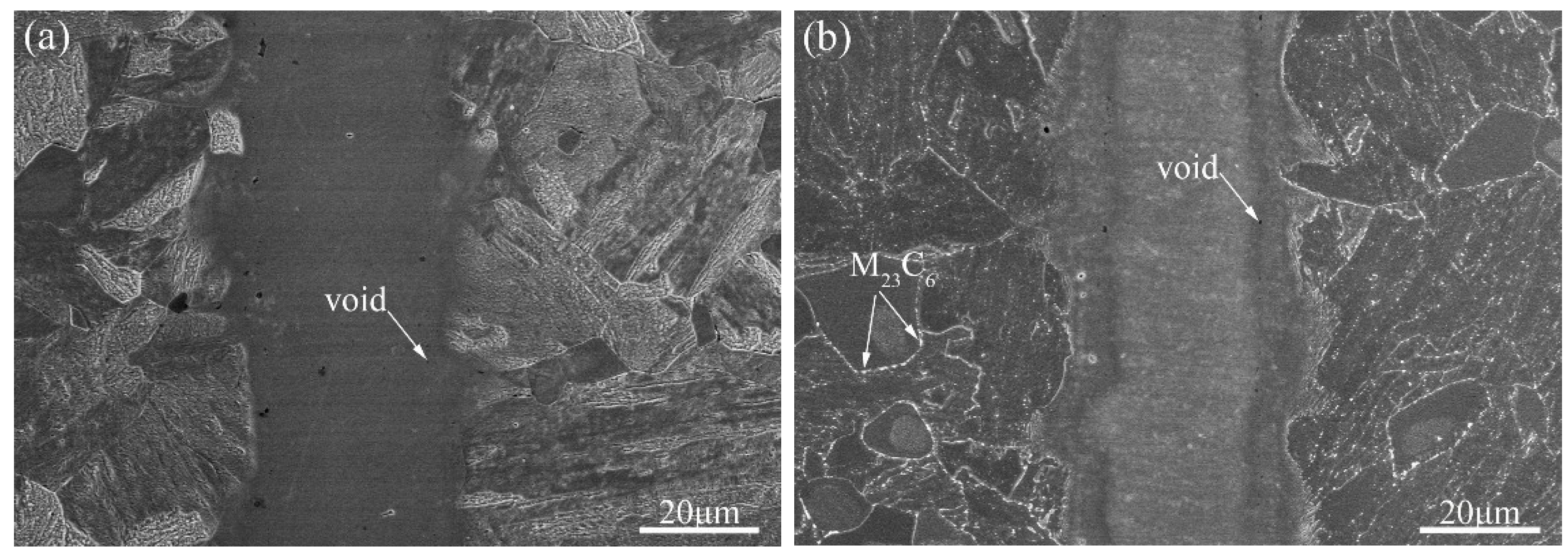
Figure 2 shows the interfacial microstructure of the diffusion-bonded joints before and after tempering treatment. The intermediate part is the interlayer of nickel and the contrast was opposite to that of the microstructures on both sides of the intermediate layer. Lath martensite and a small amount of δ-ferrite compose the microstructures on both sides of the intermediate layer. Two types of precipitates are usually formed along lath martensite and prior austenite boundaries during the tempering process, mainly M23C6 and MX [24]. M23C6 carbide and MX carbonitride facilitate the dispersion strengthening of 9Cr martensitic/ferritic heat-resistant steels during heat treatment [14,25,26,27]. MX carbonitride is much smaller than M23C6 carbide. M23C6 carbides are mainly distributed along lath, block, packet, and prior austenite grain boundaries, while MX carbonitrides are mainly distributed in the lath. Thus, the precipitates along the boundaries were identified as M23C6 type carbides, shown in Figure 2b. In addition, few voids were observed in the region adjacent to parent materials on both sides of the Ni/steel interface and no crack occurred in the joint region.
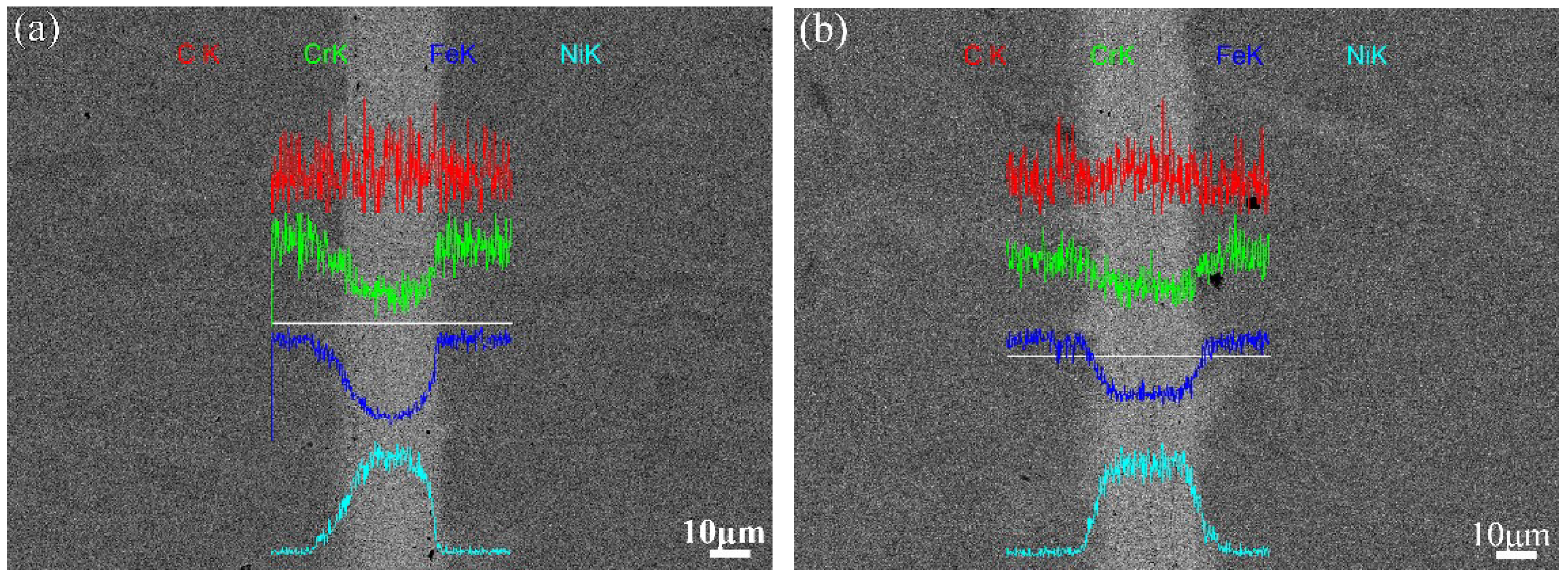
The nickel, iron, and chromium atoms interdiffused at the steel/Ni interfaces during the diffusion bonding process. At the bonding temperature, iron and nickel formed continuous solid solutions with irregular shapes. The qualitative line analyses for Ni, Fe, and Cr across the joint are also superimposed in Figure 3 to show these elements’ distribution. The alloying element transition was relatively smooth without evident gradient. It was observed that the most Fe atoms were enriched in the region adjacent to the base metal and depleted in the central part. The distribution of Cr showed a similar pattern to that of Fe. The Ni component was concentrated in the center part, and less Ni was detected at the two sides off the central part. Meanwhile, the solid-state diffusion bonding process was also constrained by grain boundary diffusion and volume diffusion, which plays an important role in the atomic motion of alloying elements [28,29].
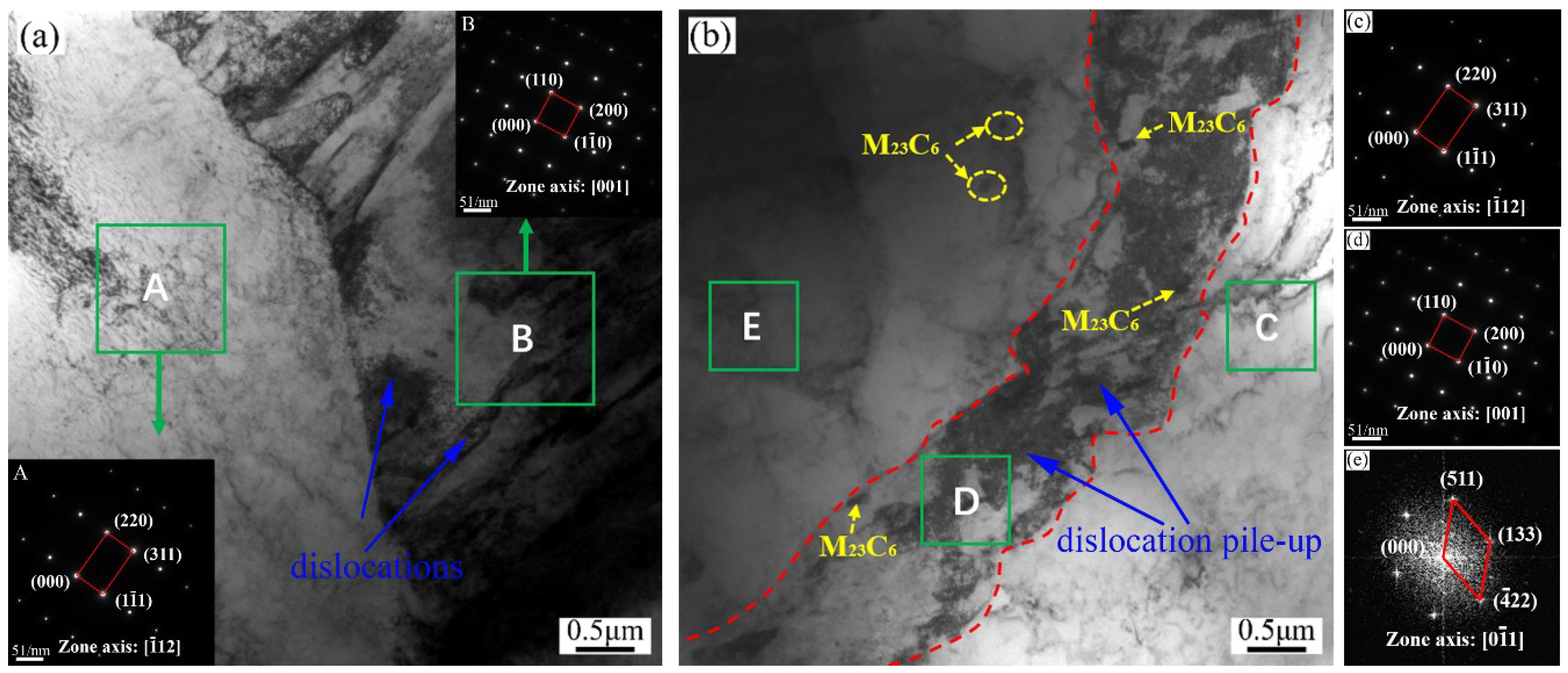
To reveal more details about interfacial microstructure, Figure 4 presents TEM images of the joint region before and after tempering treatment. No intermetallic compounds and reaction products were observed, as shown in Figure 4. This is in good agreement with the reported information of the binary phase diagrams for Fe–Ni and Cr–Ni [30]. At 1050 °C, which is higher than the austenization temperature of martensitic/ferritic steel, the material transforms into austenite, leading to the formation of many prior austenite boundaries. The formed prior austenite boundaries can accelerate the grain boundary diffusion of the alloying elements as additional diffusion paths [20]. In addition, it has been reported that nickel diffuses faster than iron and chromium in stainless steel alloys [20]. Referring to binary phase diagrams for Fe–Ni, Ni-rich solid solutions of the (γFe,Ni) forms along both sides of the bonding interface in the parent materials, which would promote good bonding between steels and interlayer. During cooling after diffusion bonding, austenite will transform into martensite laths, as shown in Figure 4a. A high density of tangled dislocations in martensite laths was also found due to large lattice distortions during martensite transformation. Meanwhile, Ni-rich solid solutions retained austenite structure, as nickel element promotes austenite stability at room temperature. Nevertheless, the austenite structure adjacent to the solid solution in steels is metastable because of less enrichment in nickel content, so it would transform into martensite at room temperature. After tempering treatment, the prior martensite transformed into tempered martensite composed of a ferrite matrix with carbide precipitates. Although massive carbide particles precipitated along the prior austenite and martensite lath boundaries during the tempering treatment, the dislocation density in martensite laths reduced significantly due to dislocation recovery. As shown in Figure 4b, the microstructure in region C is retained austenite according to the selected-area diffraction pattern (SADP). It is also the (γFe,Ni) solid solution rich in nickel, as confirmed by EDS analysis, listed in Table 3. Additionally, regions D and E consisted of tempered martensite. The interface in region D still had a higher density of dislocations and less nickel content, since the dislocation recovery was hindered by solute atoms [31]. This elucidates that nickel atoms diffuse faster and concentrate in steels, resulting in the formation of Ni-rich solid solutions.
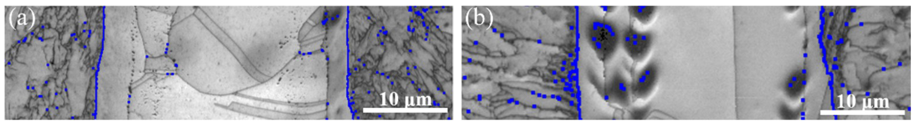
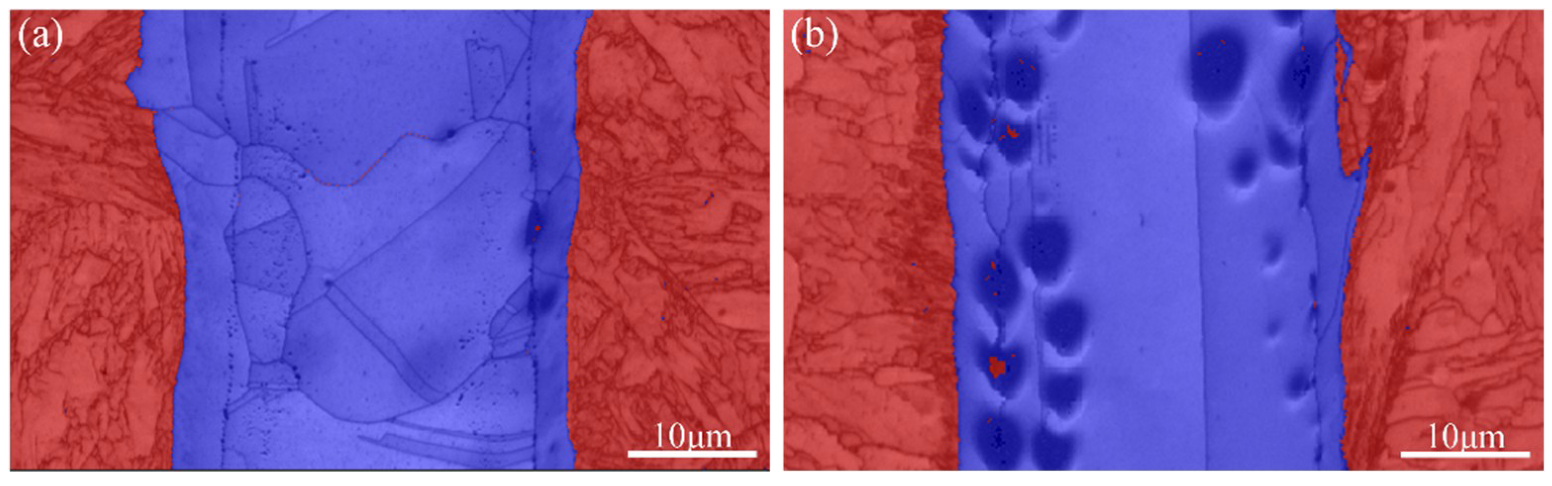
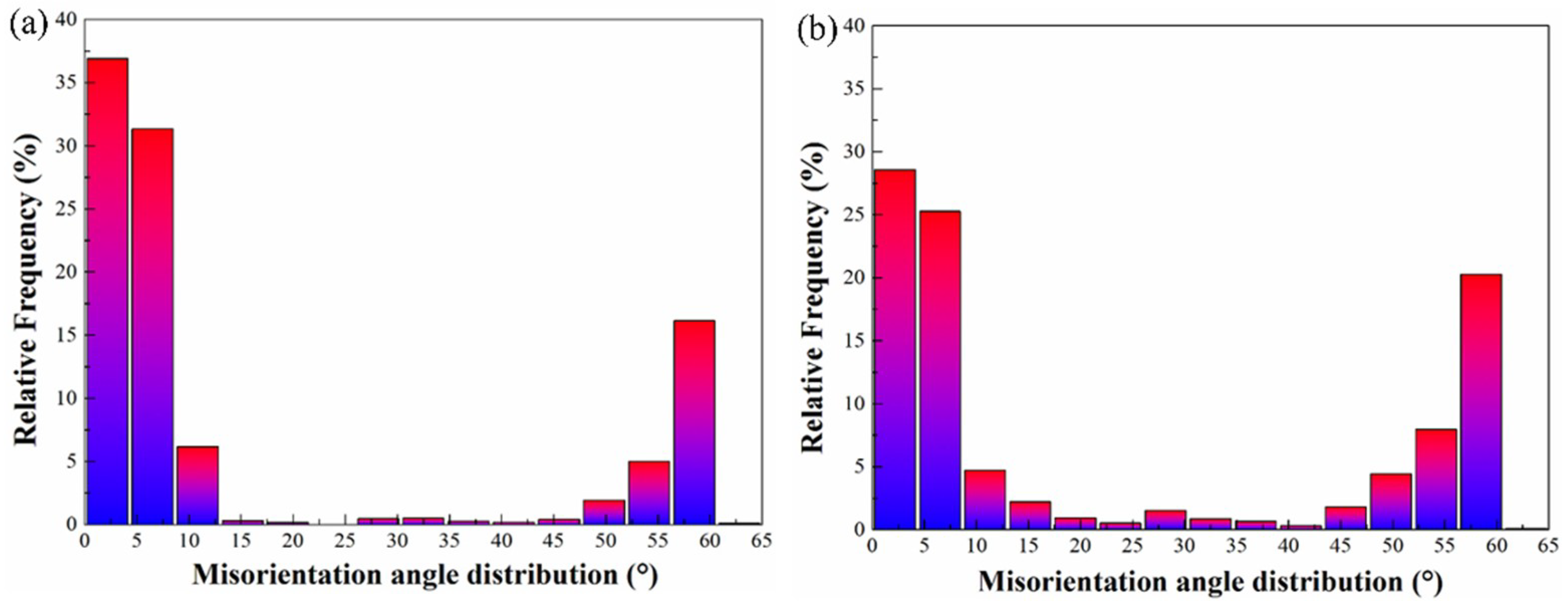
Figure 5 shows the corresponding band contrast (BC) maps from an area of joint region. After analyzing the microstructural constituents of martensite and austenite on the interface highlighted with blue lines, a Kurdjumov–Sachs (K-S) orientation relationship (OR) , between martensite and austenite could be identified [32]. With the transformation of austenite during diffusion bonding, the crystallographic orientation relationships are maintained, thus the retained austenite exists on both sides of the interface [33]. A phase map displays the distribution of martensite and austenite in Figure 6. In addition, misorientation angle distribution before and after the tempering treatment is illustrated in Figure 7. During tempering treatment, the small-angle grain boundaries between the martensite laths disappear and the adjacent laths merge together in good agreement with reliable statistical analysis, attributed to moving, merging, and recombination of the dislocations [34].
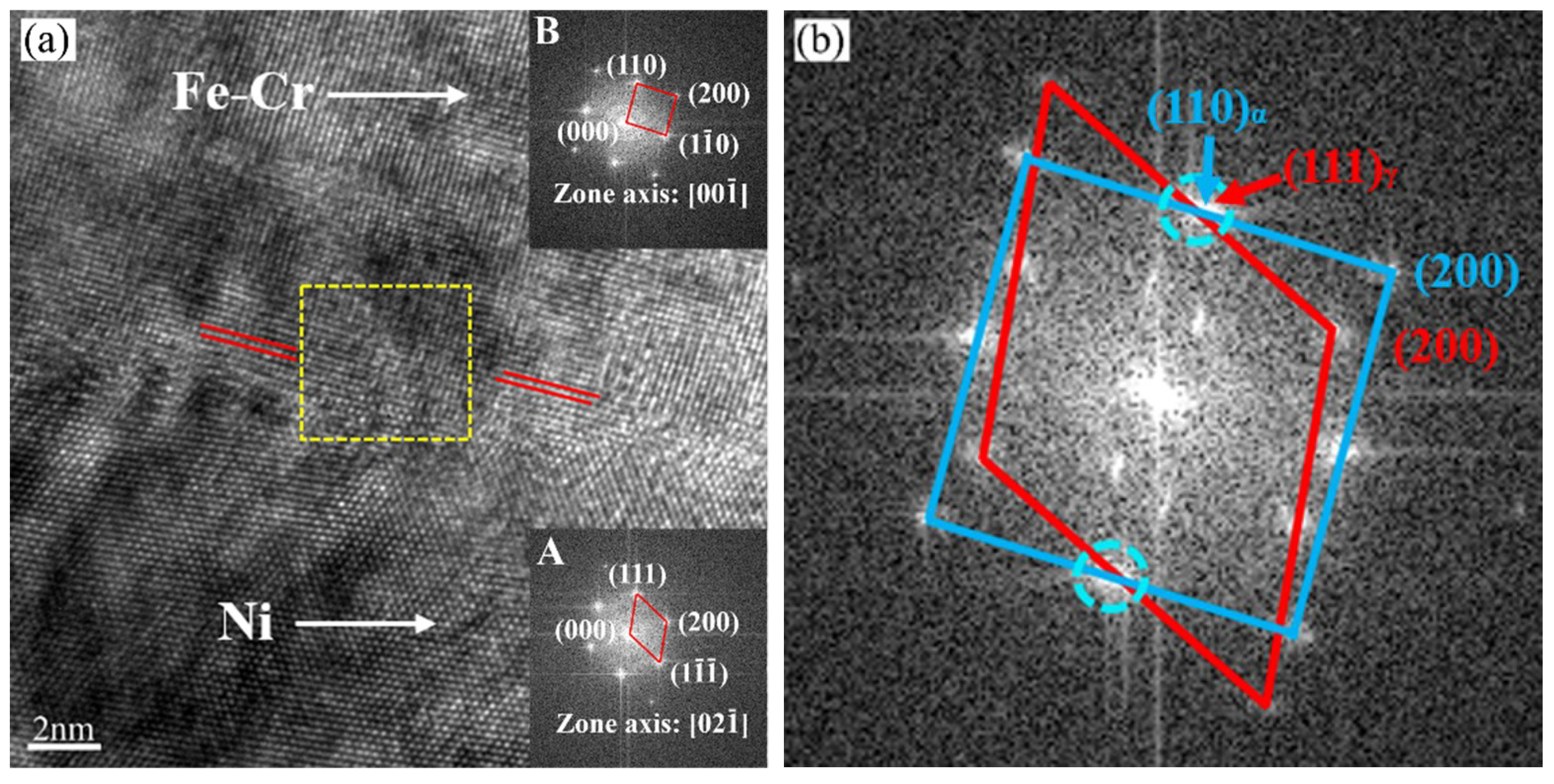
The high-resolution transmission electron microscopy (HRTEM, JEM-2100f, JEOL, Akishima, Tokyo, Japan) observation of bonding interface subjected to tempering treatment with the corresponding fast fourier transform (FFT) analysis is illustrated in Figure 8. Inset A exhibits an face-centered cubic (FCC) crystal structure along the direction and reveals that this area consists of Ni-rich retained austenite. Inset B is determined to be steel that was oriented parallel to the zone axis. In general, the diffusion bonding process may give rise to γ/α′ lattice distortion at the joint transition region, thereby influencing their mismatch status, as depicted by the intersecting arrows in Figure 8. Therefore, the value of lattice misfit δ can reflect the joint quality of the welded joint. The γ/α′ misfitted at the joint interface can be calculated quantitatively using the equation
where and are the interplanar spacing of and , respectively. The joint interface revealed a slightly positive lattice misfit δ value of 1.23%, indicating good interfacial bonding. Simultaneously, Figure 8b shows that the and planes of the retained austenite are parallel to the and planes of the martensite, respectively. This is probably related to the positive misfitting at the joint region based on the orientation relationship.
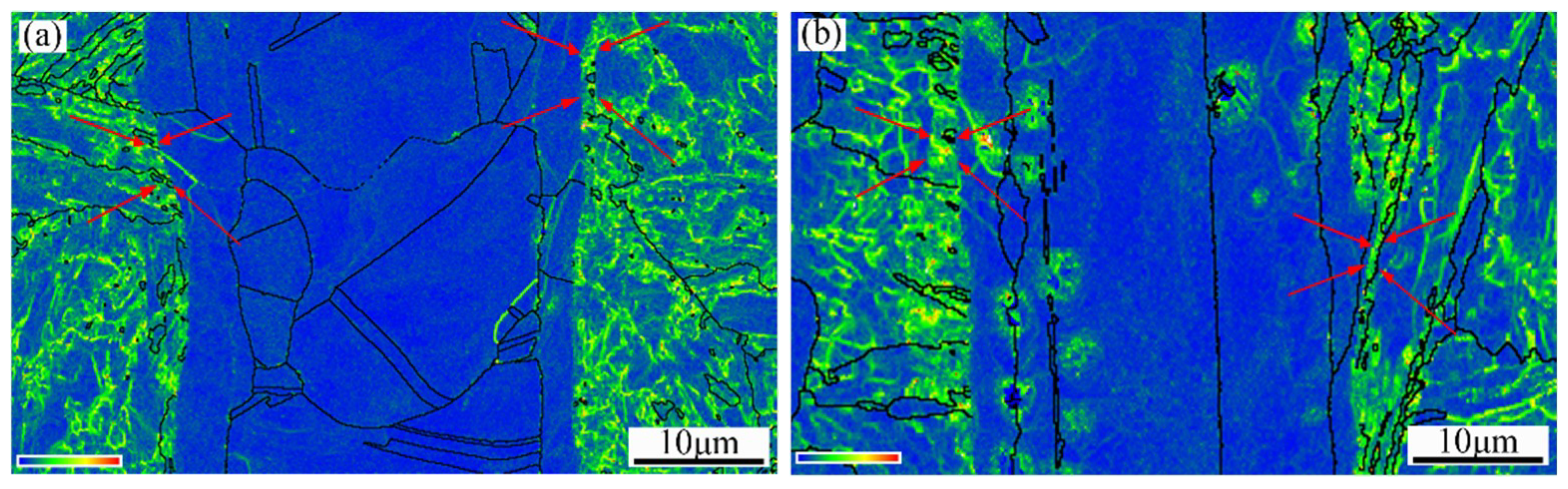
Martensite transformation would produce a high density of dislocations during the bonding cooling process. Then, the dislocation density in the tempered martensite would decrease after tempering treatment. Kernel average misorientation (KAM) maps were used to evaluate the dislocation density by changes in local orientation. KAM calculated the average misorientation surrounding a measurement point with respect to a defined set of nearest or nearest plus second-nearest neighbor points, representing a density of geometrically necessary dislocations [35]. The KAM distribution of samples before and after tempering treatment is given in Figure 9. As shown in Figure 9a, the joint region without tempering shows high KAM values, which contains a high dislocation density. The distribution of KAM values almost keeps invariant close to the bonding interface in steels, while KAM values and dislocation density both show a moderate downward trend in other regions after tempering treatment. This indicates that the dislocation density close to bonding interface in steels is almost the same, due to the pinning effect of solute atoms. This promotes appreciable solid solution strengthening along the joint interface during the post–weld heat treatment. The retained austenite along the joint interface would relieve the local stress concentration and reduce the chance of microcrack formation in the steel during deformation [36].
3.2. Tensile Tests of Joints
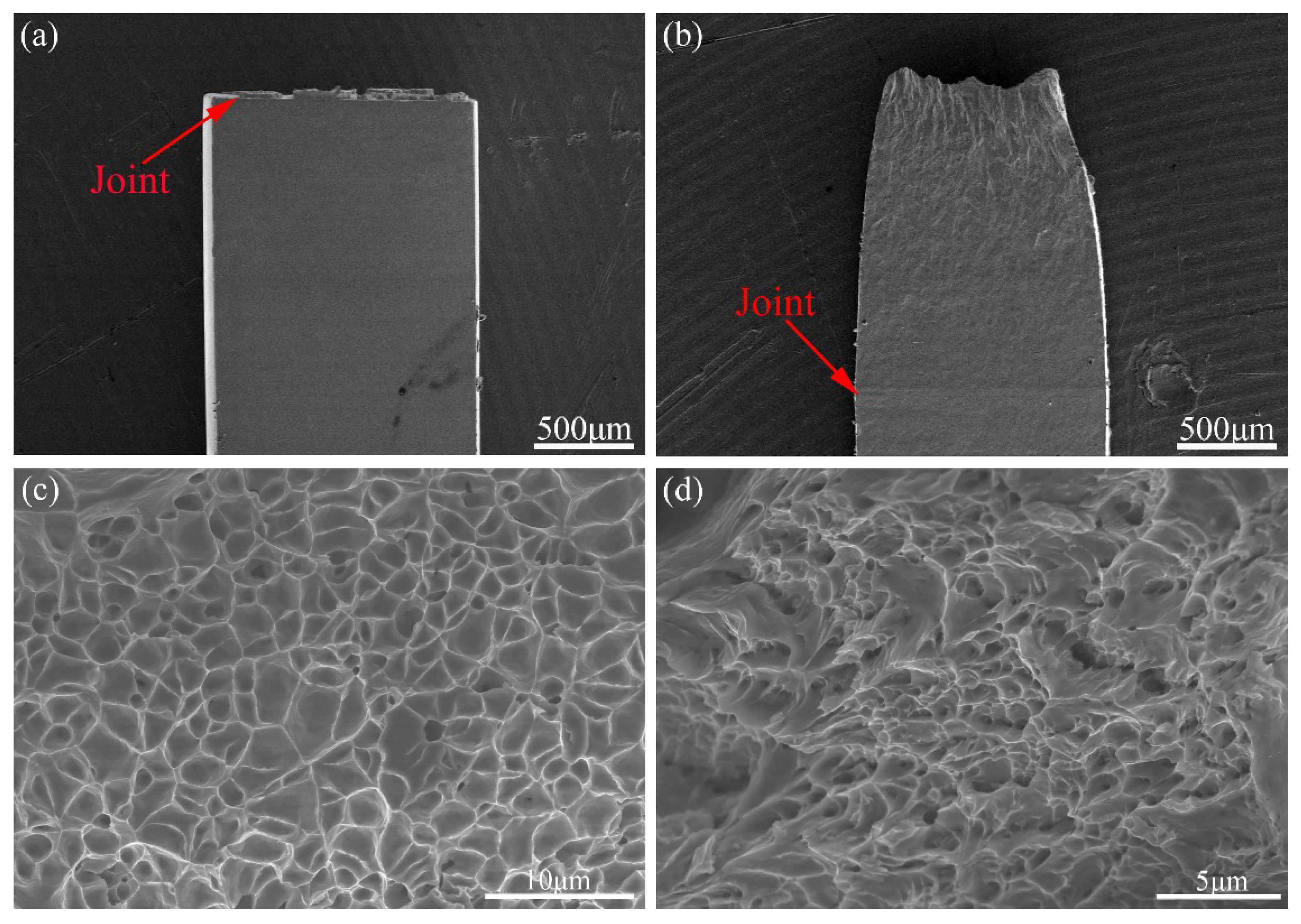
Tensile strength tests at room temperature were performed to assess the reliability of the joint attained by diffusion bonding at 1050 °C for 60 min. Figure 10 shows the engineering stress–strain curve of the base material after tempering as well as the joints before and after tempering. It was observed that the joints before tempering exhibited uniform deformation but no yield point phenomenon before fracture. The tensile strength of the joints before tempering was determined to be 905 MPa, which was consistent with the result in the literature [20]. Furthermore, the fracture of the joint took place at the electroplated nickel layer, as shown in Figure 11a. This might be due to the residual stress concentration near the bonding interface [34]. The presence of the residual stress concentration always decreased the strength and reliability of the joints.
To obtain a stable tempered martensite in the steel and enhance the mechanical properties of the joint, tempering treatment after the diffusion bonding process was carried out. The joints of martensitic/ferritic steels are usually used in tempered condition. The stress–strain curve of the matrix and joint after tempering showed no visible yield point phenomenon, and necking occurred when maximum strength of the engineering stress–strain curve was reached, as shown in Figure 10. Meanwhile, they exhibited plastic deformation before fracture, resulting in a larger overall tensile plasticity or elongation to failure than that of the joints before tempering. The tensile strength of the joints subjected to tempering treatment was determined to be 463 MPa. The tensile specimens always fractured in the base material after tempering treatment, as shown in Figure 11b. These phenomena seem to be affected by the phase transformation behavior and residual stresses at the joint region. As mentioned above, during the tempering process, plenty of precipitates comprising M23C6 carbide and MX carbonitride formed in the martensite and impeded the dislocation movement in the steel, consequently increasing the steel strength slightly. Nevertheless, the dislocation density in martensite decreased significantly, owing to the recovery of dislocations. The strength of tempered martensite is also much lower than that of prior martensite, with a high dislocation density. However, tempered martensite has better toughness and plasticity. Meanwhile, tempering treatment could relieve the residual stress concentration. As a result, the tempering treatment was beneficial in improving the mechanical properties of the bonding joint; in particular, it can balance the strength and plasticity of the joint. It is relevant to mention that the absence of intermetallic compounds at the joints has a beneficial effect on the overall mechanical properties of the joint. Meanwhile, Ni-rich solid solutions of the (γFe,Ni) formed adjacent to the joint interface can change the direction of crack propagation and retard the crack growth rate, owing to its austenite structure [37]. According to the KAM distribution and TEM observation, the dislocation movement was hindered by solute atoms along the interface. Accompanied by the stable and complex structures of dislocation tangle where the pinning effects could restrain the grain boundaries’ gliding and migration, it could also reduce the stress concentration and prevent the initiation of grain boundary crack, thus the joint strength was increased [31,38]. In addition, the plasticity of joints slightly improved and the local stress concentrations probably released, owing to retained austenite formed at the joint region [36], and no phase transformation occurred in the retained austenite. Although a few voids were observed at the joint interface after tempering treatment, no failure occurred. This performance indicates that the strength of joint interface is higher than that of the base materials subjected to tempering treatment. Therefore, the fairly improved comprehensive mechanical properties, especially the good combination of strength and plasticity, are attributed to the better metallurgical bond between the interlayer and the steel as well as appropriate tempering treatment.
The SEM graphs of the fracture of tensile samples before and after tempering treatment are illustrated in Figure 11. The appearance of dimples with various sizes and localized ductile shearing was detected on the fracture surface because of the high ductility of the Ni interlayer, as shown in Figure 11c. Furthermore, Figure 11d demonstrates that in the fracture surface of the joint subjected to tempering treatment, the base material underwent necking with various sizes of dimples and slight river patterns, elucidating a mixed mode of ductile and brittle fracture.
4. Conclusions
In this paper, diffusion bonding of 9Cr martensitic/ferritic heat-resistant steels with an electrodeposited Ni interlayer was developed. For the steel/Ni interface, the interdiffusion of elements formed an Ni-rich solid solution at the transition region, but no intermetallic compounds were observed. A Kurdjamov–Sachs orientation relationship (, ) was observed between the martensite and retained austenite. The retained austenite along the joint interface may have released the local stress concentration and reduced the opportunity for microcrack formation in the steel during deformation due to its greater plasticity. The tempering treatment can enhance the mechanical properties of the joint according to the tensile tests, since the joints prior to tempering treatment fractured at the interlayer, while the joints subjected to tempering treatment fractured in the base steel. After tempering treatment, the joint interface in steel still had a high density of dislocations, due to the pinning effect of solute atoms.
Author Contributions
Conceptualization, C.L.; Data curation, Y.L.; Formal analysis, Z.W.; Funding acquisition, H.L.; Investigation, Y.G. and W.L.; Methodology, Y.L., C.L., and H.L.; Project administration, H.L.; Writing—original draft, Y.G.; Writing—review and editing, Y.G. and C.L.
Funding
This research was funded by the National Magnetic Confinement Fusion Energy Research Project (grant No. 2015GB119001), the National Natural Science Foundation of China (grant No. 51501126, 51474156, and U1660201), and the Project of Natural Science Foundation of Tianjin (grant No. 18JCQNJC03300).
Conflicts of Interest
The authors declare no conflict of interest.
References
- Pan, C.H. The International Thermonuclear Experimental Reactor and the future of nuclear fusion energy. Wuli 2010, 39, 375–378. [Google Scholar]
- Klueh, R.L.; Nelson, A.T. Ferritic/martensitic steels for next-generation reactors. J. Nucl. Mater. 2007, 371, 37–52. [Google Scholar] [CrossRef]
- Zhou, X.; Liu, C.; Yu, L.; Liu, Y.; Li, H. Phase Transformation Behavior and Microstructural Control of High-Cr Martensitic/Ferritic Heat-resistant Steels for Power and Nuclear Plants: A Review. J. Mater. Sci. Technol. 2015, 31, 235–242. [Google Scholar] [CrossRef]
- Muroga, T.; Gasparotto, M.; Zinkle, S.J. Overview of materials research for fusion reactors. Fusion Eng. Des. 2002, 61, 13–25. [Google Scholar] [CrossRef]
- Baluc, N.; Gelles, D.S.; Jitsukawa, S.; Kimura, A.; Klueh, R.L.; Odette, G.R.; Schaaf, B.V.D.; Yu, J. Status of reduced activation ferritic/martensitic steel development. J. Nucl. Mater. 2007, 367, 33–41. [Google Scholar] [CrossRef]
- Mao, C.; Liu, C.; Yu, L.; Li, H.; Liu, Y. Mechanical properties and tensile deformation behavior of a reduced activated ferritic-martensitic (RAFM) steel at elevated temperatures. Mater. Sci. Eng. A 2018, 725, 283–289. [Google Scholar] [CrossRef]
- Tanigawa, H.; Gaganidze, E.; Hirose, T.; Ando, M.; Zinkle, S.J.; Lindau, R.; Diegele, E. Development of benchmark reduced activation ferritic/martensitic steels for fusion energy applications. Nucl. Fusion 2017, 57. [Google Scholar] [CrossRef]
- Aubert, P.; Tavassoli, F.; Rieth, M.; Diegele, E.; Poitevin, Y. Review of candidate welding processes of RAFM steels for ITER test blanket modules and DEMO. J. Nucl. Mater. 2011, 417, 43–50. [Google Scholar] [CrossRef]
- Hirose, T.; Shiba, K.; Ando, M.; Enoeda, M.; Akiba, M. Joining technologies of reduced activation ferritic/martensitic steel for blanket fabrication. Fusion Eng. Des. 2006, 81, 645–651. [Google Scholar] [CrossRef]
- Lee, J.S.; Park, J.Y.; Choi, B.K.; Hong, B.G.; Jung, K.J.; Jeong, Y.H. HIP joining of RAFM/RAFM steel and beryllium/RAFM steel for fabrication of the ITER TBM first wall. Met. Mater. Int. 2009, 15, 465–470. [Google Scholar] [CrossRef]
- Ku, D.Y.; Oh, S.; Ahn, M.-Y.; Yu, I.-K.; Kim, D.-H.; Cho, S.; Choi, I.-S.; Kwon, K.-B. TIG and HIP joining of Reduced Activation Ferrite/Martensitic steel for the Korean ITER–TBM. J. Nucl. Mater. 2011, 417, 67–71. [Google Scholar] [CrossRef]
- Francis, J.A.; Mazur, W.; Bhadeshia, H.K.D.H. Review Type IV cracking in ferritic power plant steels. Mater. Sci. Technol.-Lond. 2006, 22, 1387–1395. [Google Scholar] [CrossRef]
- Zhang, C.; Li, M.Q.; Li, H. Diffusion behavior at void tip and its contributions to void shrinkage during solid-state bonding. J. Mater. Sci. Technol. 2018, 34, 1449–1454. [Google Scholar] [CrossRef]
- Zhou, X.S.; Liu, Y.C.; Yu, L.M.; Liu, C.X.; Sui, G.F.; Yang, J.G. Uniaxial diffusion bonding of CLAM/CLAM steels: Microstructure and mechanical performance. J. Nucl. Mater. 2015, 461, 301–307. [Google Scholar] [CrossRef]
- Kazakov, N. Diffusion Bonding of Materials; Pergamon: Oxford, UK, 1985. [Google Scholar]
- Haneklaus, N.; Reuven, R.; Cionea, C.; Hosemann, P.; Peterson, P.F. Development of engineering parameters for low pressure diffusion bonds of 316 ss tube-to-tube sheet joints for FHR heat exchangers. In Proceedings of the TMS 2016 145th Annual Meeting & Exhibition, Nashville, TN, USA, 15–17 February 2016; pp. 583–588. [Google Scholar]
- Reuven, R.; Bolind, A.M.; Haneklaus, N.; Cionea, C.; Andreades, C.; Buster, G.; Hosemann, P.; Peterson, P.F. Ni interlayer to improve low pressure diffusion bonding of 316L ss press fit tube-to-tubesheet joints for coiled tube gas heaters. ASME J. Nucl. Radiat. Sci. 2017, 3, 030913. [Google Scholar] [CrossRef]
- Haneklaus, N.; Reuven, R.; Cionea, C.; Hosemann, P.; Peterson, P.F. Tube expansion and diffusion bonding of 316 L stainless steel tube-to-tube sheet joints using a commercial roller tube expander. J. Mater. Process. Technol. 2016, 234, 27–32. [Google Scholar] [CrossRef]
- Tiwari, S.K.; Paul, B.K. Asme Application of Nickel Nanoparticles in Diffusion Bonding of Stainless Steel Surfaces; American Society Mechanical Engineers: New York, NY, USA, 2009; pp. 441–446. [Google Scholar]
- Zhou, X.S.; Dong, Y.T.; Liu, C.X.; Liu, Y.C.; Yu, L.M.; Chen, J.G.; Li, H.J.; Yang, J.G. Transient liquid phase bonding of CLAM/CLAM steels with Ni-based amorphous foil as the interlayer. Mater. Des. 2015, 88, 1321–1325. [Google Scholar] [CrossRef]
- Zhong, Z.; Jung, H.; Hinoki, T.; Kohyama, A. Effect of joining temperature on the microstructure and strength of tungsten/ferritic steel joints diffusion bonded with a nickel interlayer. J. Mater. Process. Technol. 2010, 210, 1805–1810. [Google Scholar] [CrossRef] [Green Version]
- Zhong, Z.H.; Hinoki, T.; Kohyama, A. Effect of holding time on the microstructure and strength of tungsten/ferritic steel joints diffusion bonded with a nickel interlayer. Mater. Sci. Eng. A 2009, 518, 167–173. [Google Scholar] [CrossRef]
- Kundu, S.; Chatterjee, S. Interfacial microstructure and mechanical properties of diffusion-bonded titanium–stainless steel joints using a nickel interlayer. Mater. Sci. Eng. A 2006, 425, 107–113. [Google Scholar] [CrossRef]
- Abe, F. Precipitate design for creep strengthening of 9% Cr tempered martensitic steel for ultra-supercritical power plants. Sci. Technol. Adv. Mater. 2008, 9, 013002. [Google Scholar] [CrossRef]
- Chen, J.; Liu, C.; Liu, Y.; Yan, B.; Li, H. Effects of tantalum content on the microstructure and mechanical properties of low-carbon RAFM steel. J. Nucl. Mater. 2016, 479, 295–301. [Google Scholar] [CrossRef]
- Chen, J.G.; Liu, Y.C.; Xiao, Y.T.; Liu, Y.H.; Liu, C.X.; Li, H.J. Improvement of High-Temperature Mechanical Properties of Low-Carbon RAFM Steel by MX Precipitates. Acta Metall. Sin.-Engl. Lett. 2018, 31, 706–712. [Google Scholar] [CrossRef]
- Yan, B.Y.; Liu, Y.C.; Wang, Z.J.; Liu, C.X.; Si, Y.H.; Li, H.J.; Yu, J.X. The Effect of Precipitate Evolution on Austenite Grain Growth in RAFM Steel. Materials 2017, 10, 1017. [Google Scholar] [CrossRef]
- Rabkin, E.; Klinger, L.; Izyumova, T.; Semenov, V.N. Diffusion-induced grain boundary porosity in NiAl. Scr. Mater. 2000, 42, 1031–1037. [Google Scholar] [CrossRef]
- Balluffi, R.W. Grain boundary diffusion mechanisms in metals. Metall. Trans. B 1982, 13, 527–553. [Google Scholar] [CrossRef]
- Yu, J.Q.; Yi, W.Z.; Chen, B.D.; Chen, H.J. Phase Diagram of Binary Alloys; University of Shanghai for Science and Technology: Shanghai, China, 1987. [Google Scholar]
- Peng, K.P.; Qian, K.W.; Chen, W.Z. Effect of dynamic strain aging on high temperature properties of austenitic stainless steel. Mater. Sci. Eng. A 2004, 379, 372–377. [Google Scholar] [CrossRef]
- Zhang, Y.J.; Miyamoto, G.; Shinbo, K.; Furuhara, T. Effects of α/γ orientation relationship on VC interphase precipitation in low-carbon steels. Scr. Mater. 2013, 69, 17–20. [Google Scholar] [CrossRef]
- Kitahara, H.; Ueji, R.; Tsuji, N.; Minamino, Y. Crystallographic features of lath martensite in low-carbon steel. Acta Mater. 2006, 54, 1279–1288. [Google Scholar] [CrossRef]
- Zhang, Y.; Zhan, D.; Qi, X.; Jiang, Z.; Zhang, H. Microstructure and mechanical properties of Cr14 ultra-high-strength steel at different tempering temperatures around 773 K. Mater. Sci. Eng. A 2017, 698, 152–161. [Google Scholar] [CrossRef]
- Shirazi, H.; Miyamoto, G.; Nedjad, S.H.; Chiba, T.; Ahmadabadi, M.N.; Furuhara, T. Microstructure evolution during austenite reversion in Fe-Ni martensitic alloys. Acta Mater. 2018, 144, 269–280. [Google Scholar] [CrossRef]
- Shi, X.; Zeng, W.; Zhao, Q.; Peng, W.; Kang, C. Study on the microstructure and mechanical properties of Aermet 100 steel at the tempering temperature around 482 °C. J. Alloys Compd. 2016, 679, 184–190. [Google Scholar] [CrossRef]
- Wang, C.; Zhang, C.; Yang, Z.; Su, J.; Weng, Y. Analysis of fracture toughness in high Co–Ni secondary hardening steel using FEM. Mater. Sci. Eng. A 2015, 646, 1–7. [Google Scholar] [CrossRef]
- Zhou, H.W.; Fang, J.F.; Chen, Y.; Yang, L.; Zhang, H.; Lu, Y.; He, Y.Z. Internal friction studies on dynamic strain aging in P91 ferritic steel. Mater. Sci. Eng. A 2016, 676, 361–365. [Google Scholar] [CrossRef]
Figure 1.
(a) Schematic diagram of diffusion bonding and tempering treatment of 9Cr martensitic/ferritic heat-resistant steel with an electrodeposited Ni interlayer; (b) schematic drawing of tensile specimen; (c) schematic drawing of clamping method.
Figure 1.
(a) Schematic diagram of diffusion bonding and tempering treatment of 9Cr martensitic/ferritic heat-resistant steel with an electrodeposited Ni interlayer; (b) schematic drawing of tensile specimen; (c) schematic drawing of clamping method.

Figure 2.
Microstructure of the joint interface: (a) prior to tempering treatment and (b) subject to tempering treatment.
Figure 2.
Microstructure of the joint interface: (a) prior to tempering treatment and (b) subject to tempering treatment.

Figure 3.
Back-scattered electron (BSE) scanning electron microscopy (SEM) micrographs of the joint interface with qualitative line analysis: (a) prior to tempering treatment and (b) subject to tempering treatment. The white line indicates the energy dispersive X-ray spectroscopy (EDS) line scanning area across the joint.

Figure 4.
Brightfield transmission electron micrographs (TEMs) at the joint or Ni/steel interface and corresponding fast fourier transform (FFT) diagram: (a) prior to tempering treatment and (b) subject to tempering treatment. (c,d) show the selected-area diffraction pattern (SADP) of fixed area marked with green rectangles, (e) SADP of the M23C6 indicated by the arrow in b.

Figure 5.
Corresponding band contrast (BC) maps from an area of joint region: (a) prior to tempering treatment and (b) subject to tempering treatment.
Figure 5.
Corresponding band contrast (BC) maps from an area of joint region: (a) prior to tempering treatment and (b) subject to tempering treatment.

Figure 6.
Phase map acquired by electron back-scattered diffraction (EBSD) for the joint regions (a) before and (b) after tempering treatment. Red represents α-phase and blue represents γ-phase.
Figure 6.
Phase map acquired by electron back-scattered diffraction (EBSD) for the joint regions (a) before and (b) after tempering treatment. Red represents α-phase and blue represents γ-phase.

Figure 7.
Misorientation angle distribution: (a) prior to tempering treatment and (b) subject to tempering treatment.
Figure 7.
Misorientation angle distribution: (a) prior to tempering treatment and (b) subject to tempering treatment.

Figure 8.
High-resolution transmission electron microscopy (HRTEM) observation of the joint interface subjected to tempering treatment and the corresponding FFT diagram: (a) HRTEM image at Ni/steel interface; (b) corresponding FFT diagram of the region marked with a yellow rectangle in (a).
Figure 8.
High-resolution transmission electron microscopy (HRTEM) observation of the joint interface subjected to tempering treatment and the corresponding FFT diagram: (a) HRTEM image at Ni/steel interface; (b) corresponding FFT diagram of the region marked with a yellow rectangle in (a).

Figure 9.
Kernel average misorientation (KAM) maps (a) before and (b) after tempering treatment.

Figure 10.
Tensile stress–strain curve of the base material after tempering and the joint before and after tempering.
Figure 10.
Tensile stress–strain curve of the base material after tempering and the joint before and after tempering.

Figure 11.
Fracture morphology analysis of the joint surface: (a,c) prior to tempering treatment and (b,d) subject to tempering treatment.
Figure 11.
Fracture morphology analysis of the joint surface: (a,c) prior to tempering treatment and (b,d) subject to tempering treatment.


Table 1.
Chemical composition of 9Cr martensitic/ferritic heat-resistant steel in wt.%.
| Element | C | N | Cr | W | Mn | Si | V | Ta | Fe |
|---|---|---|---|---|---|---|---|---|---|
| wt.% | 0.04 | 0.02 | 8.93 | 1.71 | 0.44 | 0.04 | 0.22 | 0.073 | Bal. |
Table 2.
Electroplating bath details of electrodeposited Ni layers.
| Specimen No. | Chemical and Parameters | Data |
|---|---|---|
| 1 | Nickel sulfate | 240 g/L |
| 2 | Nickel chloride | 40 g/L |
| 3 | Boric acid | 40 g/L |
| 4 | Ammonium chloride | 40 g/L |
| 5 | Lauryl sodium sulfate | 0.15 g/L |
| 6 | Time duration | 60 min |
| 7 | Temperature | 35 °C |
| 8 | Current density | 3 A/dm2 |
| 9 | pH value | 5.8 |
Table 3.
EDS analysis results of the region marked with green rectangles in Figure 4b (wt.%).
Table 3.
EDS analysis results of the region marked with green rectangles in Figure 4b (wt.%).
| Region | A | B | C | D | E | |
|---|---|---|---|---|---|---|
| Element | ||||||
| Fe | 50.28 | 90.26 | 51.27 | 81.26 | 90.13 | |
| Ni | 40.34 | 0.7 | 39.64 | 9.51 | 0.57 | |
| Cr | 4.86 | 8.33 | 5.47 | 7.85 | 8.85 | |
| W | 4.52 | 4.5 | 3.60 | 1.35 | 0.43 | |
© 2018 by the authors. Licensee MDPI, Basel, Switzerland. This article is an open access article distributed under the terms and conditions of the Creative Commons Attribution (CC BY) license (http://creativecommons.org/licenses/by/4.0/).
Share and Cite
MDPI and ACS Style
Gao, Y.; Wang, Z.; Liu, Y.; Li, W.; Liu, C.; Li, H. Diffusion Bonding of 9Cr Martensitic/Ferritic Heat-Resistant Steels with an Electrodeposited Ni Interlayer. Metals 2018, 8, 1012. https://doi.org/10.3390/met8121012
AMA Style
Gao Y, Wang Z, Liu Y, Li W, Liu C, Li H. Diffusion Bonding of 9Cr Martensitic/Ferritic Heat-Resistant Steels with an Electrodeposited Ni Interlayer. Metals. 2018; 8(12):1012. https://doi.org/10.3390/met8121012
Chicago/Turabian StyleGao, Yan, Zumin Wang, Yongchang Liu, Wenchao Li, Chenxi Liu, and Huijun Li. 2018. "Diffusion Bonding of 9Cr Martensitic/Ferritic Heat-Resistant Steels with an Electrodeposited Ni Interlayer" Metals 8, no. 12: 1012. https://doi.org/10.3390/met8121012
Note that from the first issue of 2016, this journal uses article numbers instead of page numbers. See further details here.