The Effect of Deep Cryogenic Treatment on the Corrosion Behavior of Mg-7Y-1.5Nd Magnesium Alloy

Marine Corrosion and Protection Centre, Institute of Oceanology, Chinese Academy of Sciences, No. 7 Nanhai Road, Qingdao 266071, China
*
Author to whom correspondence should be addressed.
Metals 2017, 7(10), 427; https://doi.org/10.3390/met7100427
Submission received: 28 August 2017
/
Revised: 27 September 2017
/
Accepted: 10 October 2017
/
Published: 13 October 2017
(This article belongs to the Special Issue Corrosion of Magnesium Alloys)
Abstract
:The effect of quenching on the corrosion resistance of Mg-7Y-1.5Nd alloy was investigated. The as-cast alloy was homogenized at 535 °C for 24 h, followed by quenching in air, water, and liquid nitrogen. Then, all of the samples were peak-aged at 225 °C for 14 h. The microstructures were studied by scanning electron microscopy, energy-dispersive spectrometry, and X-ray diffraction. Corrosion behavior was analyzed by using weight loss rate and gas collection. Electrochemical characterizations revealed that the T4-deep cryogenic sample displayed the strongest corrosion resistance among all of the samples. A new square phase was discovered in the microstructure of the T6-deep cryogenic sample; this phase was hugely responsible for the corrosion property. Cryogenic treatment significantly improved the corrosion resistance of Mg-7Y-1.5Nd alloy.
1. Introduction
Magnesium alloys contained rare earths have been widely used in aerospace applications because of their excellent mechanical properties [1]. Researchers have successfully developed many commercial Mg-RE alloys, including WE43, WE54, and EW75 alloys [2,3,4,5]. Heat treatment is vital in the transformation of precipitated phases and the redistribution of alloying elements, which contribute to improve mechanical property of Mg-RE alloys [6,7].
Recently, many researchers studies have exerted considerable effort to elucidate the influence of heat treatment on the mechanical strength, corrosion property, and creep resistance of Mg-RE alloys [8,9]. Rokhlin et al. [10] examined the characteristic features of the precipitated phase in a ternary Mg-Nd-Y system, thereby gaining an insight into volume transformation and the kinetics of solid solution decomposition. Xin et al. [11] demonstrated that aging precipitation significantly reduced the strength anisotropy of the extruded Mg-Y-Nd alloy. Zhu et al. [12] analyzed the serrated flow and tensile properties of Mg-Y-Nd alloys, and that they found that serrated flow is due to interactions between dislocations and solute atoms. Various precipitations (e.g., Mg3Nd, Mg12YNd, Mg3(Y, Nd), etc.) may form in a Mg-Y-Nd system [13]. The majority of previous studies have focused on the relationship between precipitations and mechanical strength. Thus, the effects of precipitations on the corrosion behavior of Mg-Y-Nd alloys remain unclear [14,15]. Ben-Hamu et al. [16] investigated the relationship between the microstructure and corrosion behavior of Mg-Y-Gd-Zr alloys; they found that after 3 h of aging, the samples exhibited a stronger better corrosion resistance than that of grains with zirconium-depleted edge areas. Jiang et al. [17] explored the corrosion behavior of extrusion, under-aged, peaked-aged, and over-aged WE93 alloys, particularly with regard to corrosion rates, corrosion products, and heat treatment effects. Ma et al. [18] assessed the as-cast, T4, and T6 conditions of Mg-5Y-1.5Nd alloys to reveal the influence of precipitated phases on corrosion resistance during heat treatment; they demonstrated that heat treatment significantly affected the micro-galvanic corrosion between cathodic precipitated phases and the anodic α-Mg matrix.
Deep cryogenic heat treatment is a conventional supplementary treatment for metals to improve their wear resistance and hardness of steels [19,20,21]. Numerous works have recently focused on the effects of cryogenic treatment on Mg-Al alloys. Yong et al. [22] claimed that cryogenic treatment improved the mechanical property and corrosion resistance of AZ91 Mg alloys because of the altered distribution of precipitated phases. Liu et al. [23] studied the effect of cryogenic treatment on the microstructure and mechanical properties of Mg-1.5Zn-0.15Gd alloys; their results revealed that numerous ω phase particles precipitated from the Mg matrix after cryogenic treatment. The volume fraction of ω phase particles increased as the cryogenic treatment duration was increased from 1 min to 24 h, and the ductility of alloy was enhanced by 79%. Kamran et al. [24] found that deep cryogenic heat treatment improved the hardness and wear resistance of on AZ91 alloys. When compared to conventional heat treatment, deep cryogenic treatment can change the size and distribution of precipitated phases in the magnesium alloys more effectively, and improve the microstructure of magnesium alloys by placing the samples in an ultra-low temperature environment. The literature consistently suggests that as grain size decreases, the corrosion resistance of Mg is improved in neutral and alkaline sodium chloride electrolytes. A fine-grained microstructure will form a better passive film on the surface of magnesium alloys [25]. Therefore, deep cryogenic treatment may improve the corrosion resistance of magnesium alloys to some extent. Nonetheless, limited information is available regarding the effects of different precipitated phases on the corrosion resistance of Mg-RE alloys exposed to deep cryogenic heat treatment.
The present study object consisted of Mg-7Y-1.5Nd alloys under T4 and T6 conditions subjected to different quenching processes. The microstructure, weight loss rate, gas collection, and electrochemical characteristics of the samples were analyzed to reveal the effects of deep cryogenic heat treatment on the corrosion behavior of Mg-7Y-1.5Nd alloys.
2. Experimental Methods
2.1. Materials and Characterization
Mg-7Y-1.5Nd alloy was prepared by melting in an electrical resistance furnace (General Research Institute for Nonferrous Metals, Beijing, China) inside a steel crucible under protected gas consisting of argon (Ar) and tetrafluoroethane (C2H2F4) to prevent burning of the melts. Mg-7Y-1.5Nd denoted that the chemical compositions were expressed in mass percent. The materials were prepared by blending the appropriate proportions from ingots of commercially pure Mg (>99.95%), Y (99.9%), and Nd (99.9%). The highest smelting temperature was 850 °C, and the cast temperature was between 720 °C and 750 °C. The samples were cut from the ingots by an electric spark linear cutting machine (General Research Institute for Nonferrous Metals, Beijing, China). Inductively coupled plasma-atomic emission spectrometry revealed that the chemical compositions of the alloy were as follows: Y, 7.11 wt. %; Nd, 1.52 wt. %; Al, 0.016 wt. %; Fe, 0.020 wt. %; and balance Mg.
The details of the heat treatment of the Mg-7Y-1.5Nd alloy are provided in Table 1. The solution treatment (T4) was performed at 535 °C for 16 h under an argon atmosphere to attain a homogenous structure of the magnesium α phase. The samples were then quenched in three different environments, namely, air (room temperature), water (20 °C), and deep cryogenic (liquid nitrogen, −196 °C) for 12 h. Aging treatment was performed at 225 °C for 14 h, which was followed by quenching in air, water, and deep cryogenic environments. The samples were completely immersed in liquid nitrogen (−196 °C) to facilitate cryogenic treatment. All of the samples in this study had dimensions of 1 cm × 1 cm × 1 cm.
To conduct microstructural analysis, the sample surfaces were etched in Picral etchant (mixture of 10 mL of acetic acid, 10 mL of ethanol, 70 mL of deionized water, and 10 mL of picric acid). The sample surfaces were then cleaned with ethanol. This etchant clarifies α and β phases. The metallographic morphology and the corroded surface were observed by scanning electron microscopy (SEM; JSF-6700F, Jeol, Tokyo, Japan) equipped with energy dispersive X-ray spectroscopy (EDS; INCA, Oxford Instruments, Abingdon, UK). The sample surfaces were then characterized by optical microscopy (OM, Carl Zeiss Jena, Wangen, Germany) and further analyzed by EDS. EDS analysis was performed to characterize the components of each sample at more than three replicate spots, and the obtained results were identical. The precipitated phases of Mg-7Y-1.5Nd alloy were identified by X-ray diffraction (XRD; D/Max 2550, Rigaku, Tokyo, Japan) with CuKα radiation operated at 40 kV and 40 mA. The XRD test step was 4°/min.
2.2. Corrosion and Electrochemical Tests
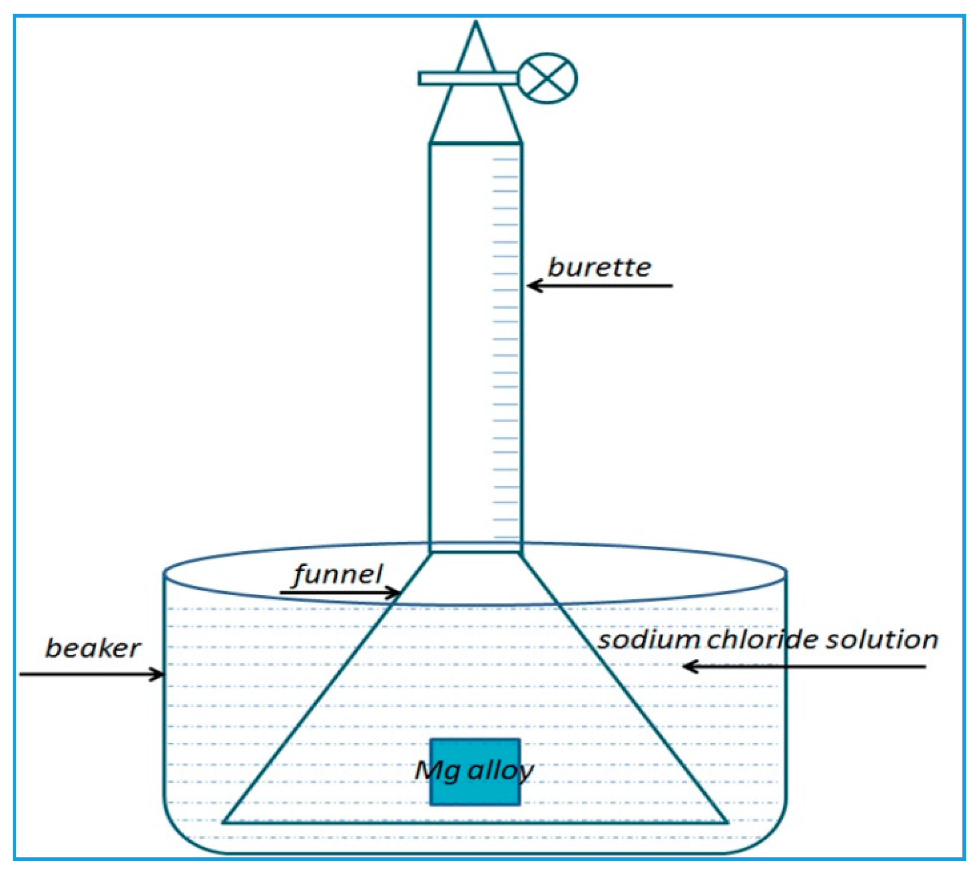
To evaluate gas collection, 1 cm × 1 cm × 1 cm cubes were prepared, weighed, and sealed using epoxy, leaving a 5 cm2 exposed surface. A funnel was inverted into the samples to transfer the generated hydrogen bubbles into a burette during immersion (Figure 1). Each sample was polished with 5000-grit SiC paper and measured thrice in 3.5% NaCl solution for 72 h.
The Mg-7Y-1.5Nd alloy samples were polished with the abrasive paper for metallographic analysis. The original weight (W0) of the samples was obtained using an analytical balance. Then, the immersion test was completed in 3.5% NaCl solution for 72 h. Each sample had three replicate samples to ensure the reliability of the results. After the immersion test, the boiling of chromic acid (20% chromium trioxide + 1% silver nitrate) was applied at 100 °C to remove the corrosion products on the surface of the Mg-7Y-1.5Nd alloy samples [26,27]. The samples without corrosion products were successively washed with deionized water and ethyl alcohol. Once the samples were dry, the final weight (W1) was obtained using an analytical balance. The original weight (W0) minus the final weight (W1) denoted the weight loss (ΔW) during the corrosion reaction. The surface morphologies of the samples without corrosion products were characterized by scanning electron microscopy.
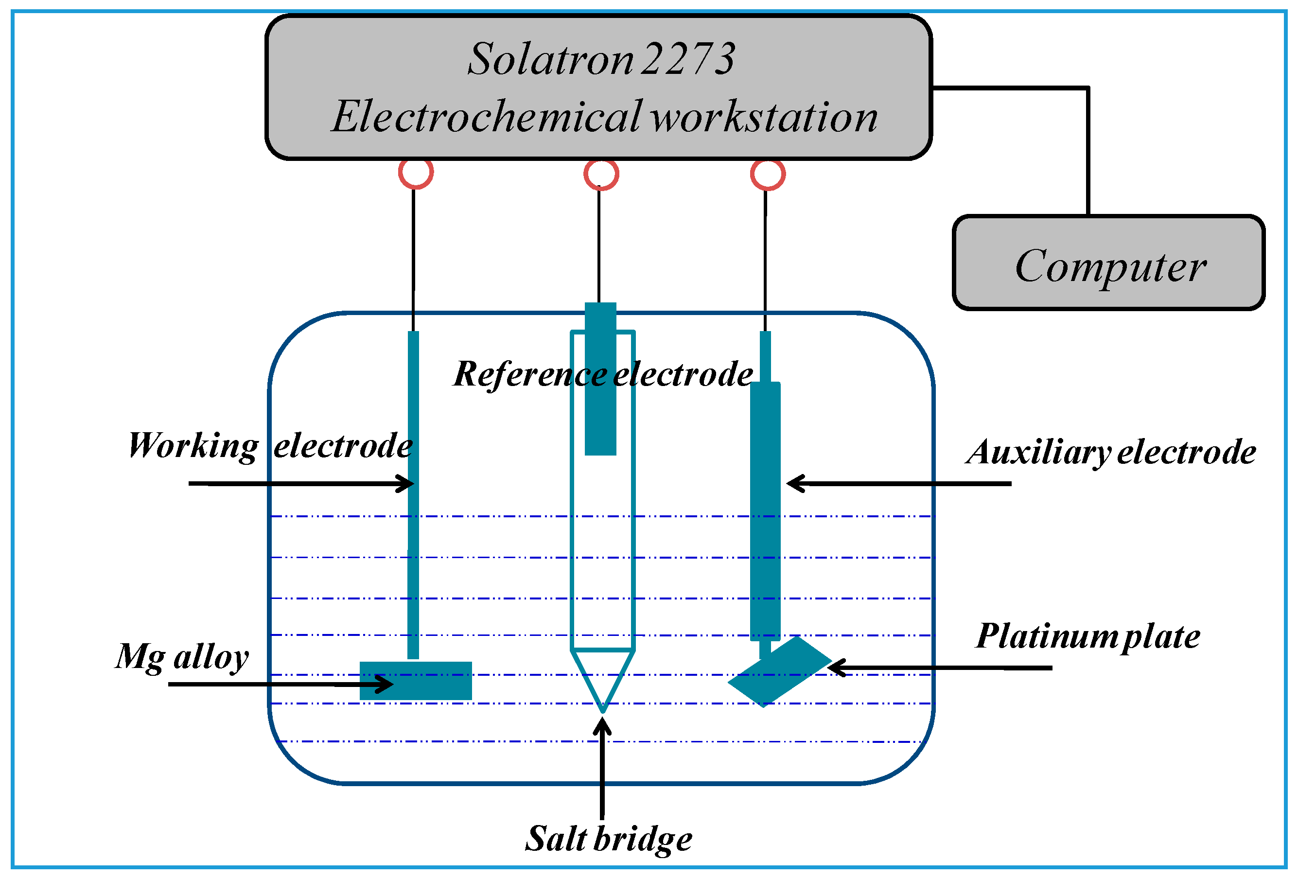
The samples for electrochemical testing consisted of 1 cm × 1 cm × 1 cm cubes. Prior to electrochemical testing, the electrodes were encapsulated in epoxy resin, leaving a 1 cm × 1 cm surface exposed. The samples were ground using a 5000-grit SiC emery paper, degreased by ethyl alcohol, and then dried by cold flowing air. The used electrolyte was 3.5% NaCl (consisting of A.R. (Analytical Reagent) NaCl and deionized water) at 25 ± 1 °C. The open circuit potential (OCP), the potentiodynamic polarization curve, and electrochemical impedance spectra were obtained by a Solatron 2273 system under a three-electrode configuration with 450 mL of electrolyte (Figure 2). A platinum foil (20 mm × 20 mm × 3 mm) and a saturated calomel electrode (SCE) acted as the counter and reference electrodes, respectively. All of the potentials were given with respect to the SCE. The potentiodynamic polarization curves were obtained at a scanning rate of 0.5 mV/s after the cell was held at the OCP for 600 s. Electrochemical impedance spectroscopy (EIS) at the OCP was conducted for 10 min. For the EIS, the frequency ranged from 100,000 Hz to 0.1 Hz, with 5 mV of amplitude of sinusoidal potential signals with respect to the OCP. Electrochemical measurements were performed in three replicates to guarantee data accuracy.
3. Results and Discussion
3.1. Microstructure of Mg-7Y-1.5Nd Alloy
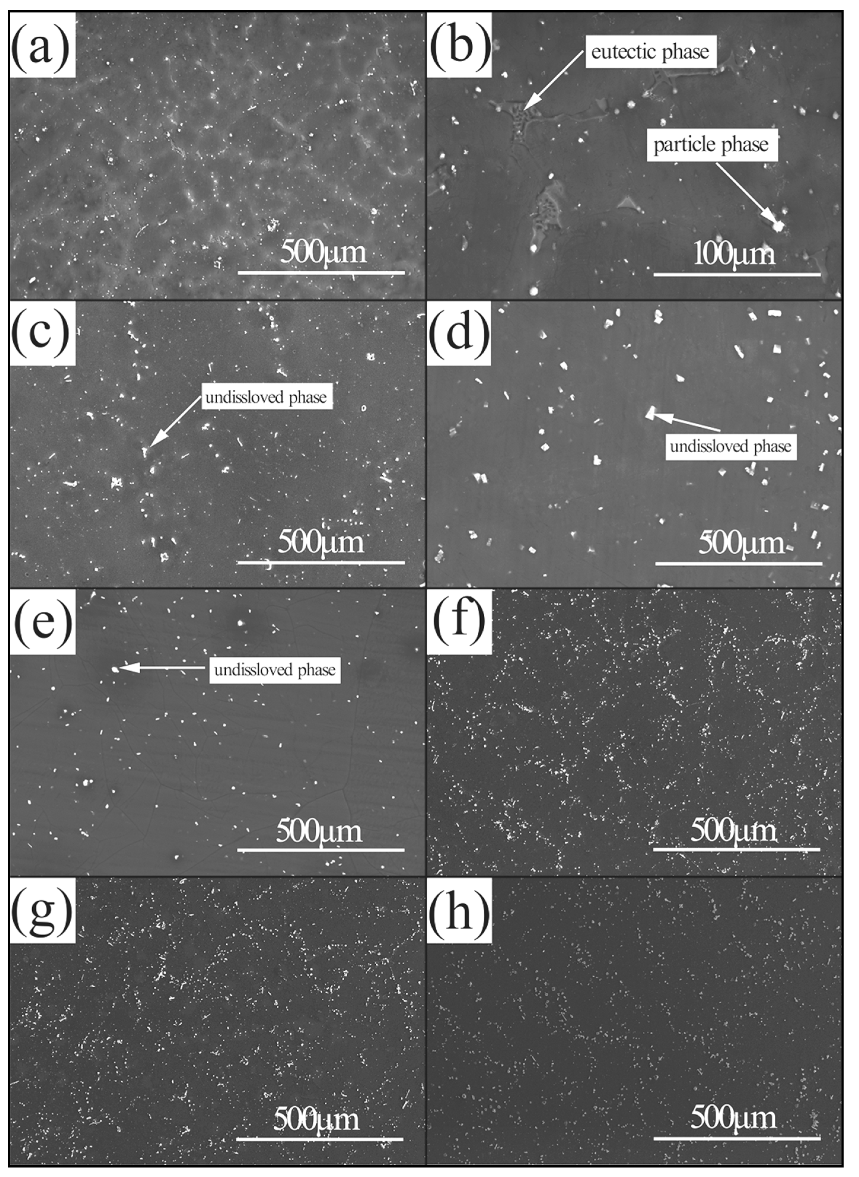
Figure 3 shows the SEM photographs of Mg-7Y-1.5Nd alloy under different conditions. As shown in Figure 3a, the microstructure of the as-cast alloy consisted of the α-Mg matrix, particle phases, and skeleton phases. The close-up view in Figure 3b reveals that a small quantity of skeleton phases was distributed on the surface of the as-cast alloy, whereas particle phases were mostly distributed discretely. The microstructure of Mg-7Y-1.5Nd alloy changed during homogenization annealing (T4). Specifically, the volume fraction of the precipitated phases decreased, and the skeleton phases became nearly invisible. The precipitated phases were almost completely dissolved except for a few particle phases, consequently producing a supersaturated α-Mg matrix. However, as shown in Figure 3c–e, the sample exposed to deep cryogenic treatment displayed the least precipitated phases, thus illustrating the inhibitory effect of ultralow temperature on precipitation during the cooling process and ultimately forming the largest supersaturated solid solution [28,29,30].
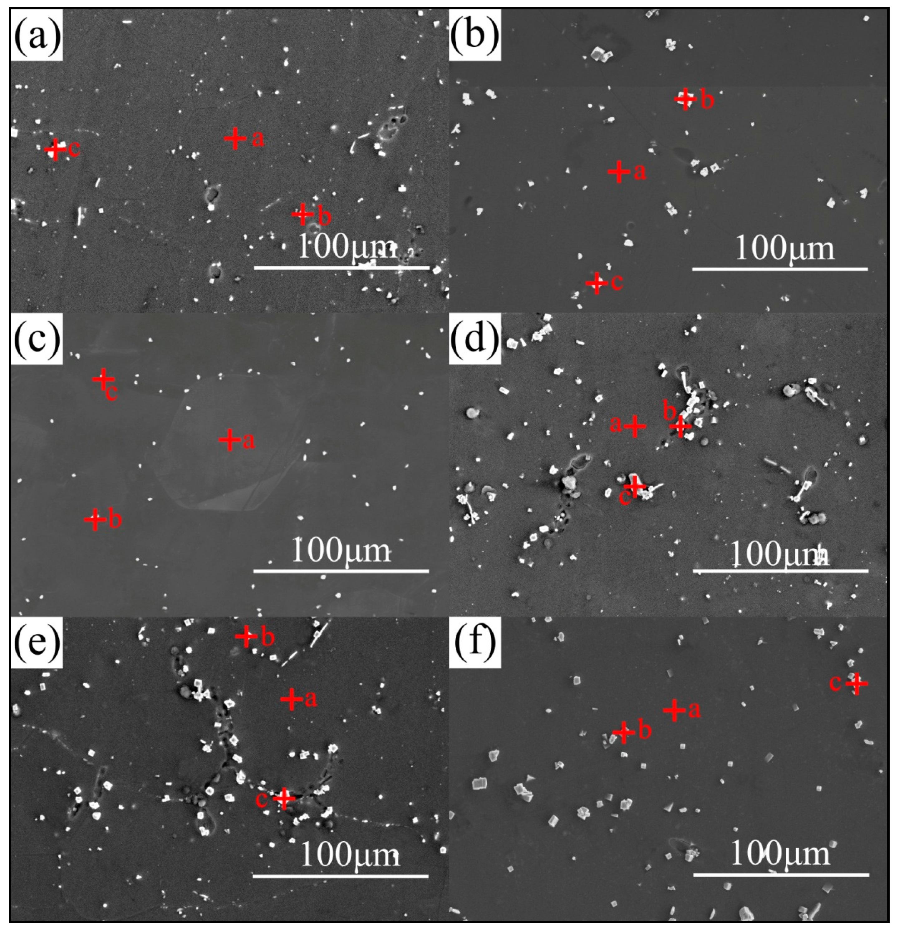
All of the samples were measured based on their close-up views. The changes in the amounts and distributions of the precipitated phases were more clearly shown during the solid-solution and aging treatments. The magnified images of the other samples are provided in Figure 4.
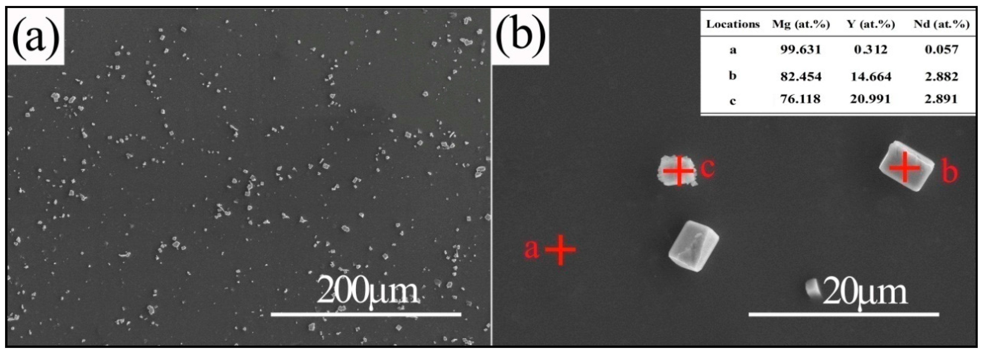
The EDS results for the different samples are presented in Table 2. The matrix location (marked “a”) contained mainly magnesium as well as few traces of yttrium and neodymium. Particle phases were marked as “b”, whereas square phases were marked as “c” (the microstructures of the T4-air and T4-cryogenic samples lacked square phases, so the particle phases marked as “c” were selected). The “b” and “c” phases contained greater amounts of rare earth elements than the “a” phase. By contrast, magnesium exhibited an opposite trend, indicating that the precipitated phases consisted mainly of intermetallics containing rare earth elements. The square phases had more rare earth elements than the particle phases. The atomic ratio of magnesium to rare earth elements of square phases was 4.8:1, whereas that of particle phases was 3:1.
After the aging treatment, particle phases precipitated along the grain boundary and within the grains of the supersaturated α-Mg phase. A small quantity of particle phases still survived the solution treatment. The solid solubility of yttrium and neodymium were 11.4 wt. % and 3.6 wt. %, respectively. The “undissolved particles” after the solidification process acted as nucleation sites during the aging treatment, after which the undissolved particles grew. An increased amount of precipitated phases was observed along the grain boundary and within the grains of the supersaturated α-Mg phase. The shape of precipitate phases depended mainly on the preferential orientation of the crystal. In addition, a small quantity of skeleton phases began to form. The aging treatment caused the Y and Nd atoms to diffuse toward the grain boundaries, thus forming precipitated phases. This phenomenon reduced the concentrations of the Y and Nd atoms in the α-Mg matrix. The difference among the aging samples was that precipitated phases were distributed more uniformly after deep cryogenic treatment, as shown in Figure 3g,h. The precipitated phases served as the cathodes of electrochemical reactions that accelerate the corrosion process [31,32].
The amplified SEM images and EDS results of the T6-cryogenic sample are shown in Figure 5. The SEM images revealed that many square phases were formed along the grain boundaries. The black matrix location (denoted by “a”) contained mainly Mg as well as trace amounts of Y and Nd. The SEM images clearly showed the white contrast square phases (denoted by “b”) and the erose phases (denoted by “c”), of which the latter had a higher Y content; their Nd contents were similar. The square phase in Figure 4 played an important role in the corrosion resistance of Mg-7Y-1.5Nd alloy.
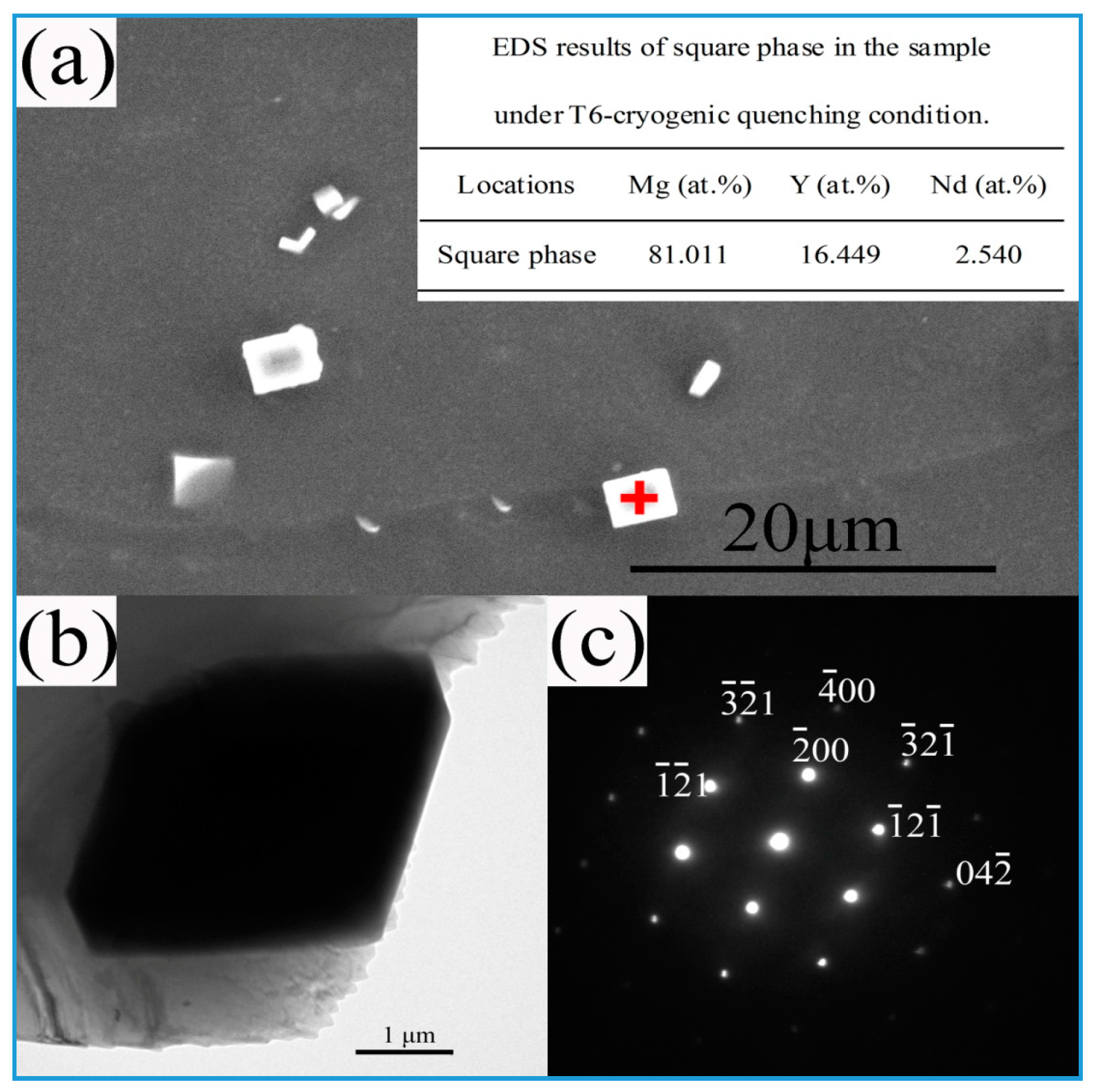
The SEM image, EDS results, TEM (transmission electron microscopy) image and SAED (selected area electron diffraction) pattern of the square phases after T6-cryogenic quenching are shown in Figure 6. The SEM images revealed that many square phases were formed along the grain boundaries. The EDS analysis demonstrates that the composition of square phase is about 81.011% Mg, 16.449% Y and 2.540% Nd in atomic percent. Based on the measured atomic ratio of Mg/(Y, Nd) in this phase and phase situation shown in Mg-Y-Nd ternary phase diagram, this phase can be concluded as Mg24(Y, Nd)5 phase. In this phase, ratio between the yttrium and neodymium atoms is discretionary, but the ratio of is nearly 24:5. This conclusion is further confirmed by XRD analysis. Figure 6b shows the TEM image of square phase and its corresponding diffraction pattern along zone axis [012]. The Mg24(Y, Nd)5 diffraction pattern is also consistent with that of stable Mg24Y5 phase in Figure 6c.
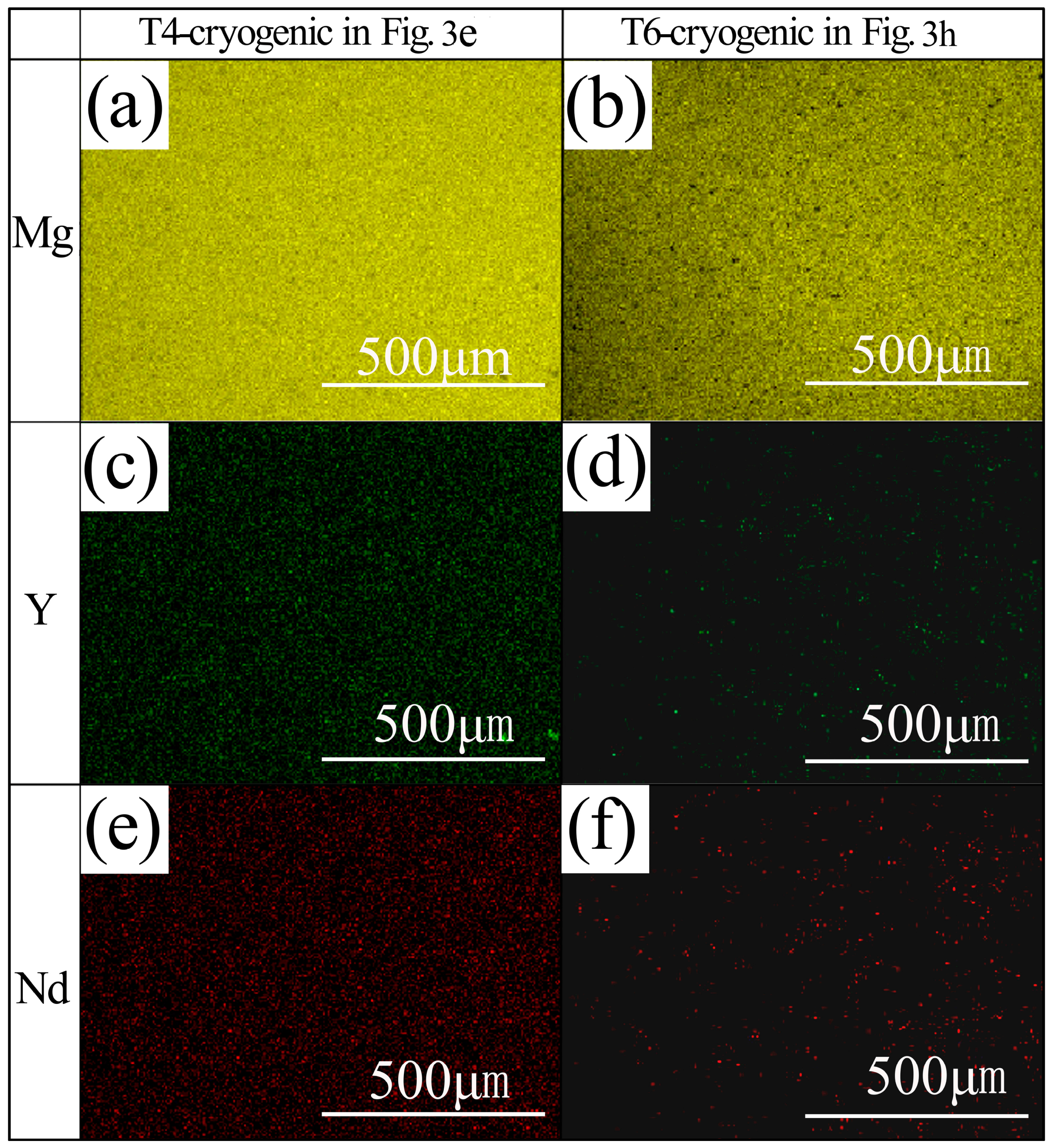
Figure 7 presents the elemental distributions (Mg, Y, and Nd) of Mg-7Y-1.5Nd alloy after cryogenic quenching. All three elements were distributed homogeneously in the α-grains after T4 heat treatment, as shown in Figure 7a,c,e, implying that the alloying elements completely dissolved back to the α-Mg matrix. However, both Y and Nd were redistributed non-uniformly after T6 heat treatment (Figure 7d,f), suggesting that the alloying elements combined with Mg to form the second phases along the grain boundary.
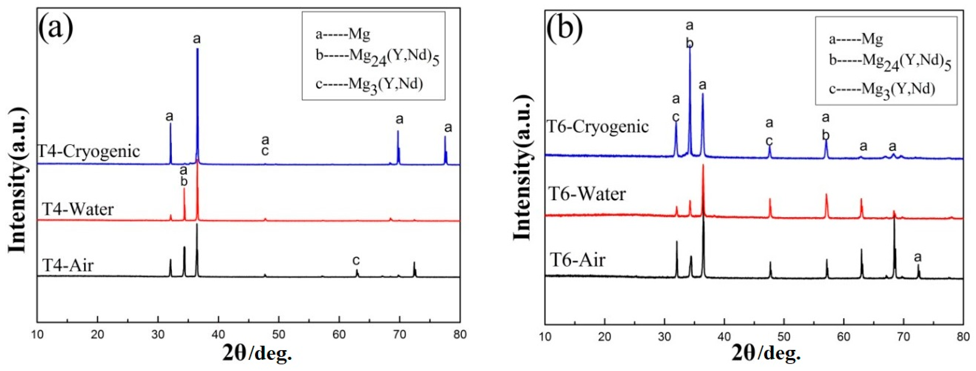
XRD was performed to characterize the components of Mg-7Y-1.5Nd alloy in three replicate samples. The results shown in Figure 8 indicated that α-Mg was the major phase, and that the precipitated phases of the as-cast, T4 and T6 samples both contain Mg24(Y, Nd)5 and Mg3(Y, Nd); this findings is consistent with Nie’s results [13,33]. “Undissolved particles” remained after the solidification process, as shown in Figure 3. During the aging treatment, these particles acted as nucleation sites for growth. An increased amount of precipitated phases manifested because of these “undissolved particles”. The precipitated phases were distributed along the grain boundary and within the grains of the supersaturated α-Mg phase. However, the types of “undissolved particles” remained unchanged after the aging treatment; thus, both precipitates b and c in the XRD test were detected in the T4 and T6 samples. The peaks of the precipitated phases were almost undetectable in the T4 sample after deep cryogenic heat treatment, implying that the alloying elements (Y and Nd) were dissolved into the Mg matrix by homogenization [34]. The Y and Nd contents in these locations were rich because of the enriched solute atoms in the solid/liquid interface during non-equilibrium solidification, even though solute atoms must be pushed into the grain boundary [35,36]. The peaks of the precipitated phases of the T6 samples had a greater intensity than those of the T4 samples, indicating that the T6 treatment promoted the precipitation by maintaining the temperature below solidus for a period. This phenomenon was consistent with the SEM images of the metallographic structure (Figure 3). The intensity of the precipitated phase was different, indicating that the Mg-7Y-1.5Nd samples had a different driving force for corrosion reaction.
3.2. Weight Loss Rate and Gas Collection
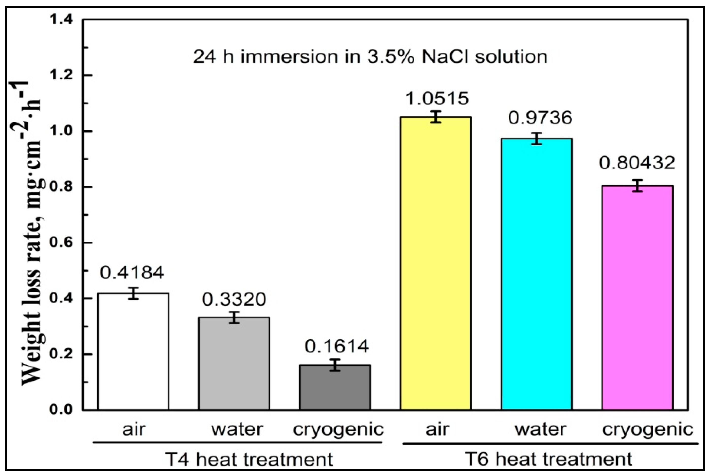
The corrosion rate ΔW (mg·cm−2·h−1) was calculated as: ΔW = (W0 − W1)/ST, W0 is the original weight (mg), W1 is the final weight without corrosion products (mg), S is the surface area (cm2), and T is the corrosion period (h). Each type had three samples, and the average value was considered as the corrosion rate. The weight loss rates of different Mg-7Y-1.5Nd alloy samples were presented in Figure 9.
As shown in Figure 9, the T4 samples had lower corrosion rates than the T6 samples because of the amount of precipitated phases formed from the α-Mg matrix during the aging process. The precipitated phases served as the cathode of the electrochemical corrosion reaction, thereby accelerating the dissolution of the α-Mg matrix. The weight loss rates of the Mg-7Y-1.5Nd alloy samples can be ordered as follows: T4-cryogenic < T4-water < T4-air < T6-cryogenic < T6-water < T6-air. The corrosion rates of the different samples were determined based on the joint effect of amount and distribution of the precipitated phases. Phases can act as effective galvanic cathodes and consequently deteriorate the corrosion performance. Nonetheless, fine and homogeneous phases were found to be better anti-corrosion barriers [37,38]. Therefore, the homogeneous square phases in the T6-cryogenic sample played an important role in improving the corrosion resistance.
The corrosion behavior of Mg in the NaCl proceeded through an electrochemical reaction with water to yield magnesium hydroxide Mg(OH)2 and hydrogen gas:
Anodic reaction: Mg → Mg2+ + 2e−
Cathodic reaction: 2H2O + 2e− → H2 + 2OH−
Overall reaction: Mg + 2H2O → Mg(OH)2 + H2
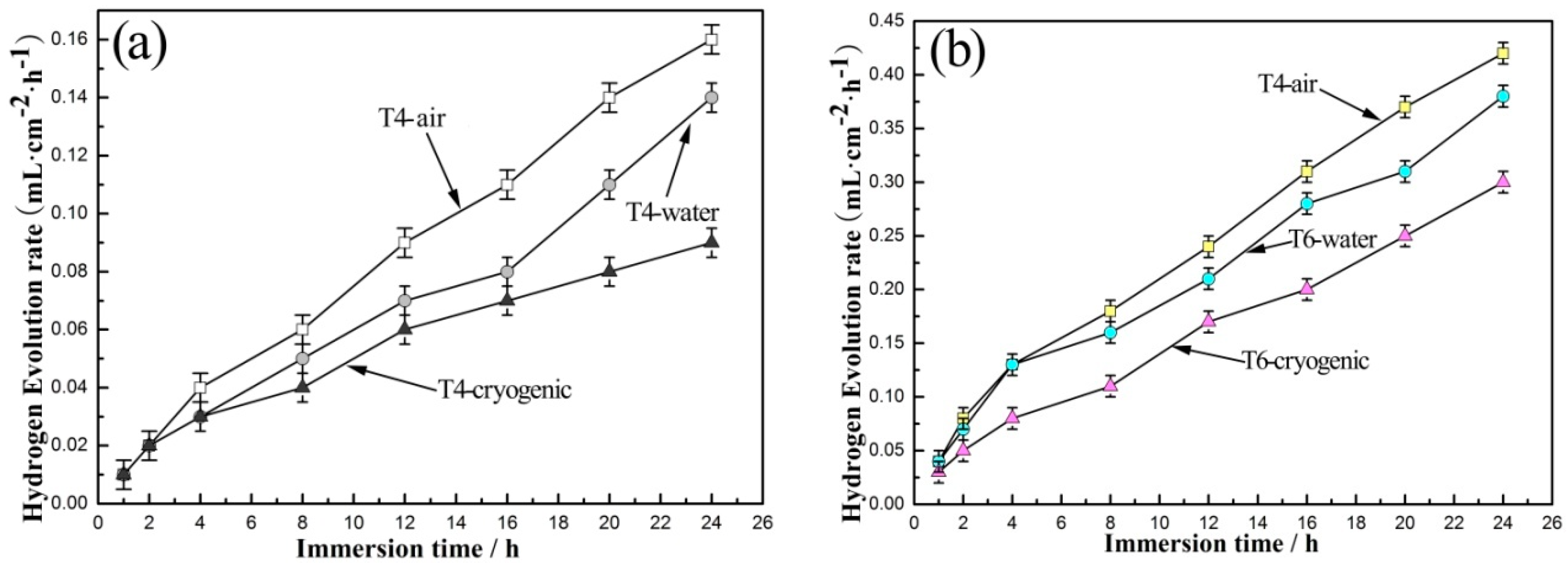
Hydroxide anions were generated by the cathodic reaction, indicating that the dissolution of one Mg atom generated one H gas molecule. That is, the evolution of one mole of hydrogen gas corresponds to the dissolution of one mole of magnesium. Therefore, in theory, measuring the volume of the evolved hydrogen is equivalent to measuring the weight loss of the dissolved magnesium. Moreover, the measured hydrogen evolution rate is equal to the weight loss rate when converted into the same units.
Gas collection was performed by employing a weight-loss method for corrosion rate testing. This strategy was convenient for calculating the average corrosion rate over a given period. The corrosion rate was investigated by conducting simultaneous hydrogen evolution and weight-loss tests on each sample. Figure 10 shows the average hydrogen evolution rates of different samples in 3.5% NaCl solution for 72 h. The corrosion rates of different Mg-7Y-1.5Nd alloy samples increased with prolonged immersion time. The T6-air sample presented the highest hydrogen evolution rates due to the amount and distribution of the precipitated phases, which acted as micro-cathodes for the micro-cells. During immersion, the law of the relative hydrogen evolution rate was similar to that of the weight loss rate (Figure 9 and Figure 10).
3.3. Electrochemical Characterization and Analysis
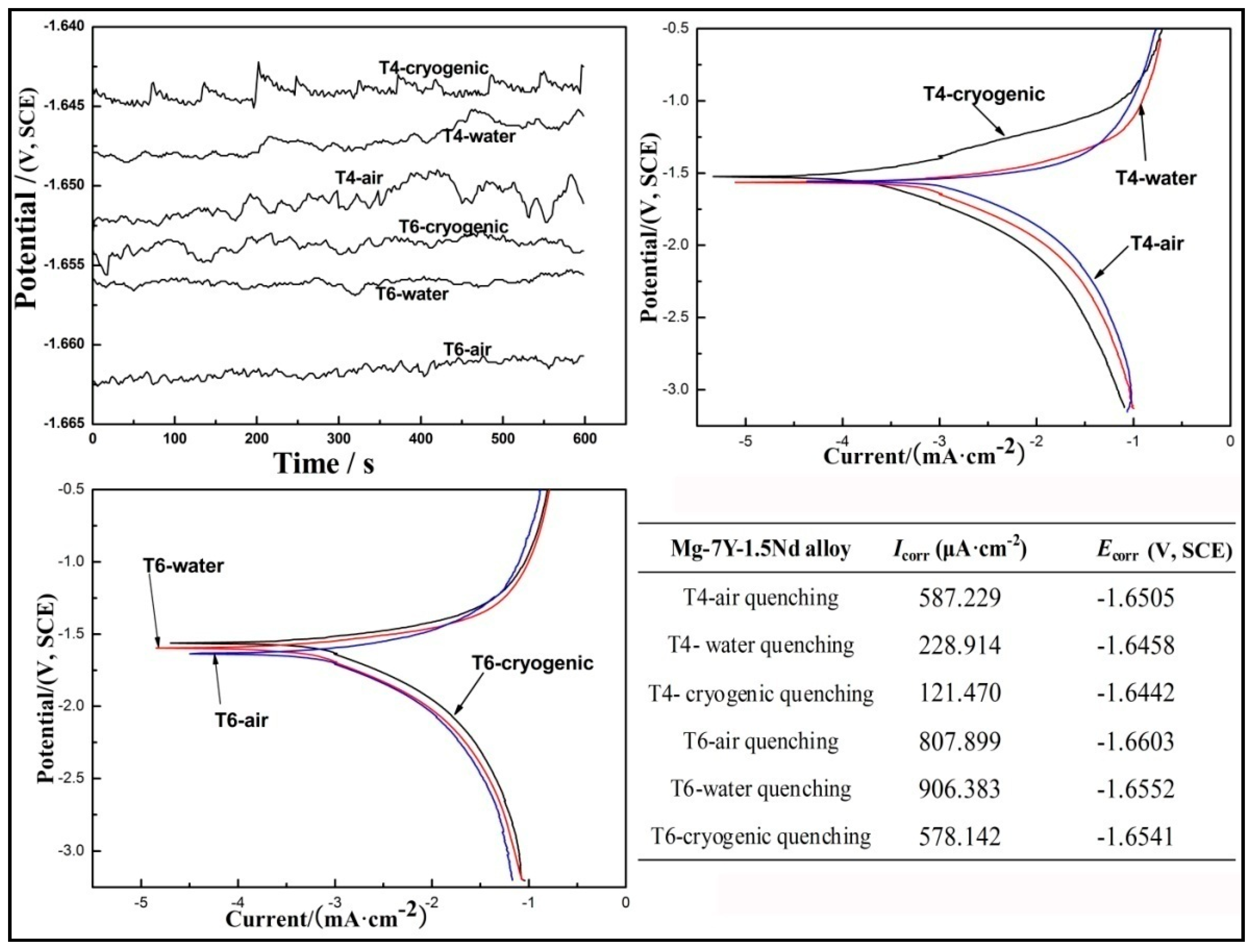
Figure 11 shows the electrochemical characterizations, corrosion potential (Ecorr), and corrosion current (Icorr) of Mg-7Y-1.5Nd alloy measured in 3.5% NaCl solution. The OCP was comparatively stable prior to measurements. A corrosion product film formed on the surface of the samples, and no clear localized corrosion occurred. The OCP curves represented the initiation and propagation of corrosion, and stable OCP values implied a steady state between the propagation of corrosion and the deposition of corrosion products [39,40]. The fluctuation of the OCP values with time was probably due to the competition between localized corrosion and passivation. For a short immersion period (600 s), the OCP of Mg-7Y-1.5Nd alloy became more and more positive with prolonged immersion time. This phenomenon may be attributed to the longer incubation period for the localized corrosion of the samples because of the stable and protective oxide film. The T4 samples exhibited a more positive OCP than the T6 samples, indicating a shorter activated period for localized corrosion, probably because of the large amount of precipitates on the grain boundaries. In addition, the OCP of the samples became stable with a prolonged immersion time, establishing a nearly steady state between the localized corrosion and the deposition of corrosion products [41]. As shown by the OCP in Figure 10, electrochemically activity of the samples can be ordered as follows: T6-air > T6-water > T6-cryogenic > T4-air > T4-water > T4-cryogenic. The T4-cryogenic sample displayed the most positive OCP because of the absence of precipitated phases on the grain boundaries, which acted as cathodes that accelerated the corrosion of the α-Mg matrix. The T6-cryogenic sample presented a better corrosion resistance than other T6 samples. This phenomenon can be attributed to the type and distribution of the precipitated phases, particularly the interaction between the impurities and dislocation of the square phases along the grain boundaries [42]. Phases played dual roles that depended on amount and distribution. The presence of phase in alloys can deteriorate corrosion performance as it could act as an effective galvanic cathode. Nonetheless, a fine and homogeneous phase was found to be a better anti-corrosion barrier.
The cathodic Tafel slopes were similar for samples under different conditions, indicating that hydrogen evolution reaction occurred [43]. The anodic branch did not exhibit Tafel characteristics, and it was not as steep as the cathodic branch, implying that the cathodic reaction played a major role in the corrosion reaction. In contrast to the anodic branch, the cathodic branch exhibited linear Tafel characteristics at potentials that are more negative than the critical pitting potential [44]. If the current associated with the oxygen reduction was neglected, and cathodic process within the Tafel region was mainly hydrogen evolution in a solution without stirring [45]. The anodic polarization curves of magnesium and its alloys were complex because of the negative difference effect, which enhanced the hydrogen evolution when the alloy was anodized. Thus, the Tafel extrapolation for calculating the corrosion current density was conducted tangentially to the cathode. Figure 11 shows the calculated corrosion current density with respect to the different quenching processes of Mg-7Y-1.5Nd alloy. The T6-air quenching sample had the largest Icorr because the amount of precipitated phases acting as the cathode of the electrochemical reaction accelerated the corrosion process. By contrast, the T4-deep quenching sample showed the smallest Icorr. These results were consistent with the weight loss rate (Figure 8) and the average hydrogen evolution rate (Figure 9). The free corrosion potential representing the corrosion tendency of different samples followed this order: T6-air > T6-water > T6-cryogenic > T4-air > T4-water > T4-cryogenic. This hierarchy was consistent with the type and distribution of precipitated phases in different samples.
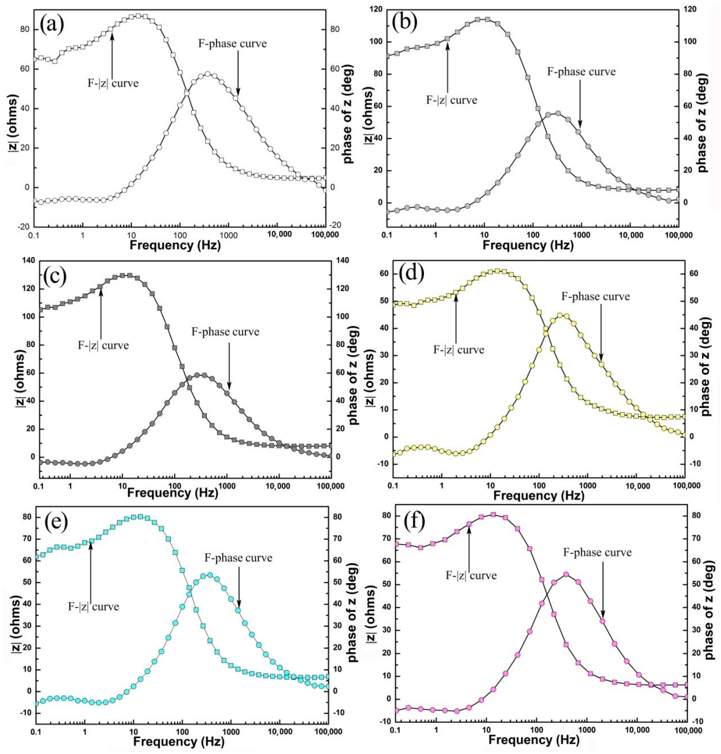
The Bode diagrams of the samples comprised two capacitive loops at high and low frequencies from the Bode diagrams in Figure 12. The change in the Bode diagrams represented the dynamic characteristics of the dissolving surfaces. The larger high frequency capacitive loop was related to the electric double layer at the electrode/electrolyte interface [46,47], and its diameter was equal to the charge transfer resistance of the working electrode. The smaller low frequency capacitive loop was due to the relaxation of mass transport of the partially protective oxide layer [48]. When the corrosion reaction proceeded, the oxide layer was progressively broken down, and the corrosion product began to form gradually. The inductive loop at low frequency was attributed to desorption of the corrosion product and the reaction of Mg+ with H2O at the damaged areas of the corrosion product film [49]. As shown in Figure 12c, the Bode diagrams of the T4-deep quenching alloy had only a single high frequency capacitive loop presumably because the adsorption and desorption of the corrosion product was too weak to be detected. This finding was consistent with the relative low corrosion rate of the T4 alloy during the initial period.
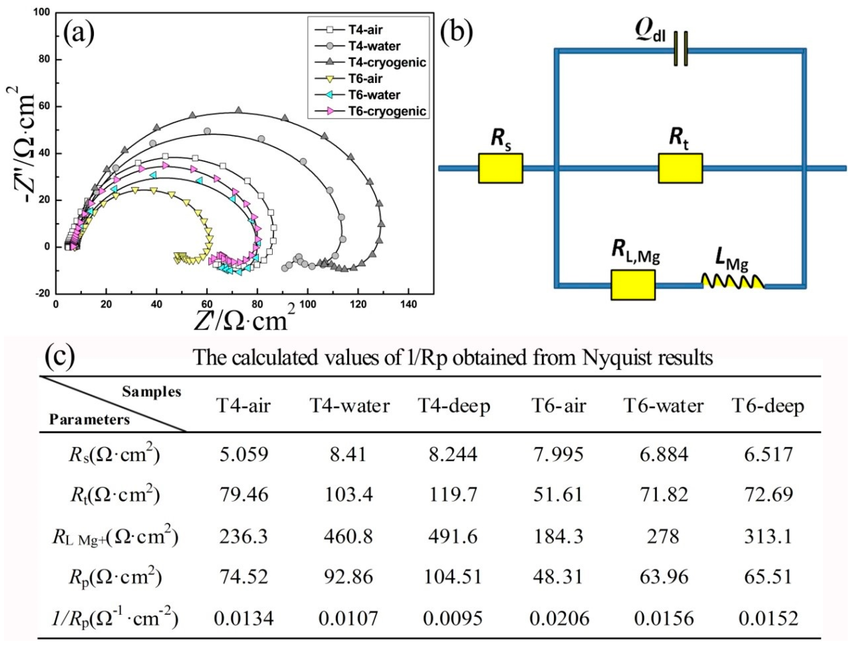
As shown in Figure 13a, the Nyquist diagrams of different Mg-7Y-1.5Nd samples exhibited varied characteristics of electrochemical reactions. The T4-deep quenching sample had the largest electrochemical impedance spectra, suggesting that the hydrogen evolution reaction was the most difficult in the α-Mg matrix. According to the Nyquist diagrams in Figure 13, the corrosion resistance of the samples can be ordered as follows: T6-air < T6-water < T6-cryogenic < T4-air < T4-water < T4-cryogenic. This finding was consistent with the results for weight loss rate, hydrogen evolution, OCP, and potentiodynamic polarization.
The Nyquist plots shown in Figure 13a, fit the equivalent circuits presented in Figure 12b. Where, Rs is the solution resistance; Rt is the charge transfer resistance, and Qdl is the constant phase element (CPE) of the electric double layer. The CPE, which served as the capacitor, was considered the deviation effect. The RLMg+ and LMg+ series connection represented the middle-frequency inductance, which described the Mg+ reaction at the damaged areas of the corrosion product film [39,42]. The polarization resistance, Rp, was an important parameter, because 1/Rp was proportional to the corrosion rate [49]. According to the equivalent circuits in Figure 12b, Rp can be calculated as follows:
The calculated values of 1/Rp for the different samples are listed in Figure 14c. The corrosion rate of the T4 sample was lower than that of the T6 sample in the immersion test. Moreover, the T4-deep quenching sample exhibited the strongest corrosion resistance among the samples. This result was consistent with the conclusions obtained from the results for weight loss rate, hydrogen evolution and Tafel extrapolation.
3.4. Corrosion Mechanism
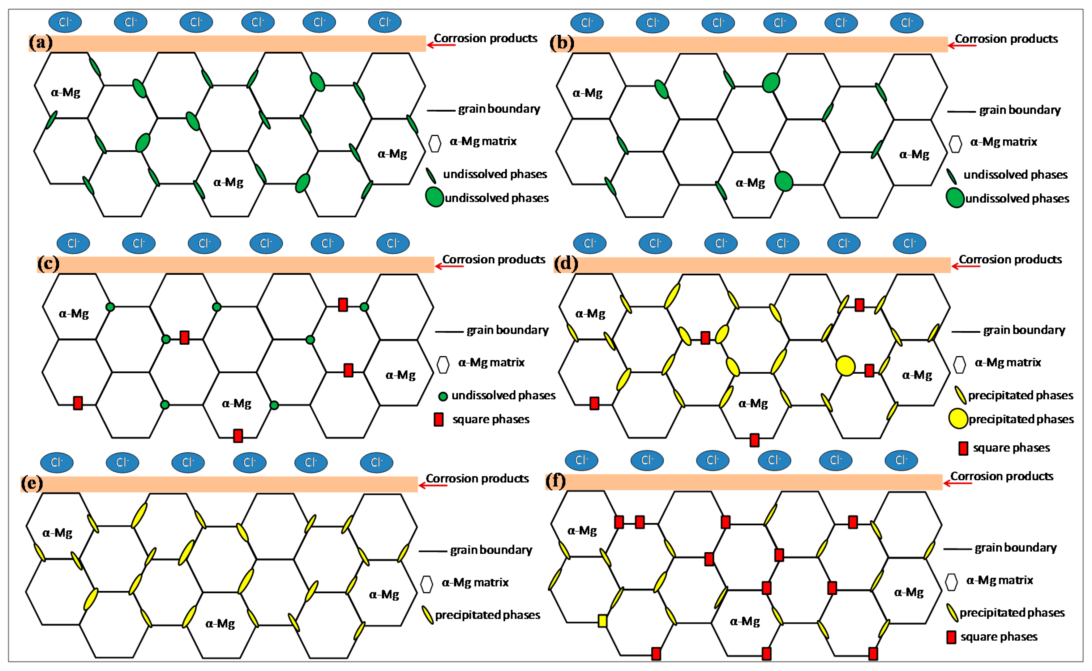
Figure 14 shows the schematic diagrams of the microstructure in relation to the corrosion mechanism. In this study, the corrosion rates of the different samples were mainly determined by the amount and distribution of the precipitations according to the classical theory proposed by Song et al. [37,38]. The phases played dual roles that depended on the amount and the distribution. The presence of phases in the alloys can deteriorate the corrosion performance because it can act as an effective galvanic cathode. Otherwise, a fine and homogeneous phase appeared to be a better anti-corrosion barrier.
Changes were observed in the volume fraction and distribution of the second phases in the Mg-7Y-1.5Nd alloy after T4 heat treatment because of the different quenching environment environments, namely, air (Figure 14a), water (Figure 14b), and liquid nitrogen (Figure 14c). The sample exposed to deep cryogenic treatment exhibited the least precipitated phases, illustrating the inhibitory effect of ultralow temperature on the precipitation during the cooling process, which formed a large supersaturated solid solution in Figure 14c. After the aging treatment, particle phases precipitated along the grain boundary and within the grains of the supersaturated α-Mg phase. The precipitated phases were distributed more uniformly after water quenching treatment (Figure 14e) and deep cryogenic treatment (Figure 14f).
Moreover, square phases formed along the boundaries, which influenced the corrosion barrier of the α-Mg matrix. This phenomenon implied that square phases had a more negative potential than the α-Mg matrix. The crystal structure of Mg24(Y, Nd)5 phase is similar to that of Mg24Y5 phase, which is a body-centered cubic (BCC) cell. The crystal structure of α-Mg is close-packed hexagonal (HCP) cell. The density of BCC cell (68%) is smaller than that of HCP cell (72%) via calculation. A larger density cell means that close-packed hexagonal (HCP) cell is more stable than body-centered cubic (BCC) cell. That means that the square phases are more chemically active than Mg matrix. In the initial stage, the square phases are preferentially dissolved as micro-anodes and the Mg matrix is protected as micro-cathodes. Then slight corrosion of Mg matrix occurs due to the non-uniform microstructure (such as defects and chemical composition) at the interiority of Mg matrix to form corrosion micro-cells. Thus, in the present work, the square phases acted as the anode to decrease the corrosion of α-Mg. The square phases were preferentially corroded instead of the α-Mg matrix, which played an important role in the retention of magnesium. A higher amount of square phases indicates a better corrosion resistance of Mg-7Y-1.5Nd alloy. However, deeper insight into square phases requires further studies.
4. Conclusions
Deep cryogenic heat treatment is a conventional supplementary treatment for improving the mechanical properties of metals. However, few studies have explored effects of deep cryogenic treatment on the corrosion resistance of magnesium alloy. This study investigated the effect of different quenching process on the corrosion resistance of Mg-7Y-1.5Nd alloy.
- (1)
- The T4 sample subjected to deep cryogenic treatment showed the least precipitated phases and formed the largest supersaturated solid solution. By contrast, the precipitated phases of the T6 sample exposed to deep cryogenic treatment were distributed more uniformly. Many square phases were formed along the grain boundaries.
- (2)
- The weight loss ratesof the Mg-7Y-1.5Nd alloy samples were arranged as follows: T4-cryogenic < T4-water < T4-air < T6-cryogenic < T6-water < T6-air. During the immersion period, the law of the relative hydrogen evolution rate was similar to that of the weight loss rate.
- (3)
- The T4-cryogenic sample showed the most positive OCP because of the absence of the precipitated phases on the grain boundaries. The polarization curves revealed that the T6-cryogenic sample had a better corrosion resistance than the other T6 samples. Both the Bode and Nyquist diagrams proved this finding.
- (4)
- The T4-deep sample had the least precipitated phases, which acted as the cathode of the electrochemical reaction for accelerating the corrosion of the α-Mg matrix. The T6-deep sample also showed a better corrosion resistance because of the uniformly distributed precipitated phases. The square phases had a more negative potential than the α-Mg matrix. The square phases were preferentially corroded instead of the α-Mg matrix, which played an important role in the retention of magnesium. A greater amount of square phases suggests a better corrosion resistance of Mg-7Y-1.5Nd alloy. Nonetheless, a deeper insight into square phases is needed.
Acknowledgments
The authors gratefully acknowledge the National Natural Science Foundation of China (Grant No. 51501181), the Fundamental Research Project of Technology Program of Qingdao (Grant No. 17-1-1-76-JCH), the Key Research and Development Program of Shandong Province (Grant No. 2017GGX20139) for providing support for this work.
Author Contributions
Quantong Jiang and Lihui Yang conceived and designed the experiments; Quantong Jiang performed the experiments; Quantong Jiang and Lihui Yang analyzed the data; Baorong Hou contributed reagents/materials/analysis tools; Quantong Jiang wrote the paper.
Conflicts of Interest
The authors declare no conflict of interest.
References
- Rokhlin, L.L. Mg Alloys Containing Rare Earth Metals; Taylor and Francis: London, UK, 2003; Volume 1, pp. 1–12. [Google Scholar]
- Liang, S.; Guan, D.; Tan, X. The relation between heat treatment and corrosion behavior of Mg-Gd-Y-Zr alloy. Mater. Des. 2011, 32, 1194–1199. [Google Scholar] [CrossRef]
- Jun, W.; Jian, M.; Zhang, D.; Tang, D. Effect of Y for enhanced age hardening response and mechanical properties of Mg-Gd-Y-Zr alloys. Mater. Sci. Eng. A 2007, 456, 78–84. [Google Scholar]
- Liu, M.; Schmutz, P.; Uggowitzer, P.J.; Song, G.; Atrens, A. The influence of yttrium (Y) on the corrosion of Mg-Y binary alloys. Corros. Sci. 2010, 52, 3687–3701. [Google Scholar] [CrossRef]
- Chang, J.; Guo, X.; He, S.; Fu, P.; Peng, L.; Ding, W. Investigation of the corrosion for Mg-xGd-3Y-0.4Zr (x = 6, 8, 10, 12 wt. %) alloys in a peak-aged condition. Corros. Sci. 2008, 50, 166–177. [Google Scholar] [CrossRef]
- Peng, Q.; Ma, N.; Fang, D.; Li, H.; Liu, R.; Tian, Y. Microstructures, aging behaviour and mechanical properties in hydrogen and chloride media of backward extruded Mg-Y based biomaterials. J. Mech. Behav. Biomed. 2013, 17, 176–185. [Google Scholar] [CrossRef] [PubMed]
- Shi, L.L.; Huang, Y.; Yang, L.; Feyerabend, F.; Mendis, C.; Willumeit, R.; Hort, N. Mechanical properties and corrosion behavior of Mg-Gd-Ca-Zr alloys for medical applications. J. Mech. Behav. Biomed. 2015, 47, 38–48. [Google Scholar] [CrossRef] [PubMed]
- Sudholz, A.D.; Gusieva, K.; Chen, X.B.; Muddle, B.C.; Gibson, M.A.; Birbilis, N. Electrochemical behaviour and corrosion of Mg-Y alloys. Corros. Sci. 2011, 53, 2277–2282. [Google Scholar] [CrossRef]
- Birbilis, N.; Easton, M.A.; Sudholz, A.D.; Zhu, S.M.; Gibson, M.A. On the corrosion of binary magnesium-rare earth alloys. Corros. Sci. 2009, 51, 683–689. [Google Scholar] [CrossRef]
- Rokhlin, L.L.; Dobatkina, T.V.; Tarytina, I.E.; Timofeev, V.N.; Balakhchi, E.E. Peculiarities of the phase relations in Mg-rich alloys of the Mg-Nd-Y system. J. Alloys Compd. 2004, 367, 17–19. [Google Scholar] [CrossRef]
- Xin, R.; Song, B.; Zeng, K.; Huang, G.; Liu, Q. Effect of aging precipitation on mechanical anisotropy of an extruded Mg-Y-Nd alloy. Mater. Des. 2012, 34, 384–388. [Google Scholar] [CrossRef]
- Zhu, S.M.; Nie, J.F. Serrated flow and tensile properties of a Mg-Y-Nd alloy. Scr. Mater. 2004, 50, 51–55. [Google Scholar] [CrossRef]
- Nie, J.F. Precipitation and hardening in magnesium alloys. Metall. Mater. Trans. A 2012, 43, 3891–3939. [Google Scholar] [CrossRef]
- Takenaka, T.; Ono, T.; Narazaki, Y.; Naka, Y.; Kawakami, M. Improvement of corrosion resistance of magnesium metal by rare earth elements. Electrochim. Acta 2007, 53, 117–121. [Google Scholar] [CrossRef]
- Zucchi, F.; Grassi, V.; Frignani, A. Electrochemical behaviour of a magnesium alloy containing rare earth elements. J. Appl. Electrochem. 2006, 36, 195–204. [Google Scholar] [CrossRef]
- Ben-Hamu, G.; Eliezer, D.; Shin, K.S.; Cohen, S. The relation between microstructure and corrosion behavior of Mg-Y-RE-Zr alloys. J. Alloys Compd. 2007, 431, 269–276. [Google Scholar] [CrossRef]
- Jiang, Q.; Ma, M.; Zhang, K.; Li, X.; Li, Y.; Shi, G.; Yuan, J. Corrosion behavior of extrusion, under-aged, peaked-aged and over-aged WE93 alloys in NaHSO3 solutions. J. Rare Earths 2014, 32, 1170–1174. [Google Scholar] [CrossRef]
- Ma, X.; Jiang, Q.; Li, Y.; Hou, B. Effect of heat treatment on corrosion behaviors of Mg-5Y-1.5Nd alloys. Int. J. Electrochem. 2016, 2016, 7097589. [Google Scholar] [CrossRef]
- Amini, K.; Akhbarizadeh, A.; Javadpour, S. Investigating the effect of the quench environment on the final microstructure and wear behavior of 1.2080 tool steel after deep cryogenic heat treatment. Mater. Des. 2013, 45, 316–322. [Google Scholar] [CrossRef]
- Gavriljuk, V.G.; Theisen, W.; Sirosh, V.V.; Polshin, E.V.; Kortmann, A.; Mogilny, G.S.; Tarusin, Y.V. Low-temperature martensitic transformation in tool steels in relation to their deep cryogenic treatment. Acta Mater. 2013, 61, 1705–1715. [Google Scholar] [CrossRef]
- Amini, K.; Araghi, A.; Akhbarizadeh, A. Effect of deep cryogenic heat treatment on the wear behavior of carburized DIN 1.7131 grade steel. Acta Metall. Sin. 2015, 28, 348–353. [Google Scholar] [CrossRef]
- Yong, J.; Ding, C.; Qiong, J. Effect of cryogenic thermocycling treatment on the structure and properties of magnesium alloy AZ91. Met. Sci. Heat Treat. 2012, 53, 589–591. [Google Scholar] [CrossRef]
- Liu, Y.; Shao, S.; Xu, C.S.; Zeng, X.S.; Yang, X.J. Effect of cryogenic treatment on the microstructure and mechanical properties of Mg-1.5Zn-0.15Gd magnesium alloy. Mater. Sci. Eng. A 2013, 588, 76–81. [Google Scholar] [CrossRef]
- Amini, K.; Akhbarizadeh, A.; Javadpour, S. Investigating the effect of quench environment and deep cryogenic treatment on the wear behavior of AZ91. Mater. Des. 2014, 54, 154–160. [Google Scholar] [CrossRef]
- Raman, R.K.S. The role of microstructure in localized corrosion of magnesium alloys. Metall. Mater. Trans. A 2004, 35, 2525–2531. [Google Scholar] [CrossRef]
- Jiang, Q.; Ma, M.; Zhang, K.; Li, X.; Li, Y.; Shi, G.; Yuan, J. The corrosion behaviors of Mg-7Gd-5Y-1Nd-0.5Zr alloy under (NH4)2SO4, NaCl and Ca(NO3)2 salts spray condition. J. Magn. Alloys 2013, 1, 230–234. [Google Scholar] [CrossRef]
- Jiang, Q.; Ma, M.; Zhang, K.; Li, X.; Li, Y.; Shi, G.; Yuan, J. Atmospheric corrosion of Mg-rare earth alloy in typical inland and marine environments. Corros. Eng. Sci. Technol. 2014, 49, 651–655. [Google Scholar] [CrossRef]
- Smola, B.; Joska, L.; Březina, V.; Stulíková, I.; Hnilica, F. Microstructure, corrosion resistance and cytocompatibility of Mg-5Y-4Rare Earth-0.5Zr (WE54) alloy. Mater. Sci. Eng. C 2012, 32, 659–664. [Google Scholar] [CrossRef]
- Zhang, X.; Yuan, G.; Mao, L.; Niu, J.; Fu, P.; Ding, W. Effects of extrusion and heat treatment on the mechanical properties and biocorrosion behaviors of a Mg-Nd-Zn-Zr alloy. J. Mech. Behav. Biomed. 2012, 7, 77–86. [Google Scholar] [CrossRef] [PubMed]
- Lu, F.; Ma, A.; Jiang, J.; Guo, Y.; Yang, D.; Song, D.; Chen, J. Significantly improved corrosion resistance of heat-treated Mg-Al-Gd alloy containing profuse needle-like precipitates within grains. Corros. Sci. 2015, 94, 171–178. [Google Scholar] [CrossRef]
- Zhou, W.; Shen, T.; Aung, N.N. Effect of heat treatment on corrosion behaviour of magnesium alloy AZ91D in simulated body fluid. Corros. Sci. 2010, 52, 1035–1041. [Google Scholar] [CrossRef]
- Gunde, P.; Furrer, A.; Hänzi, A.C.; Schmutz, P.; Uggowitzer, P.J. The influence of heat treatment and plastic deformation on the bio-degradation of a Mg-Y-RE alloy. Mater. Res. A 2010, 92, 409–418. [Google Scholar]
- Nie, J.F.; Muddle, B.C. Characterisation of strengthening precipitate phases in a Mg-Y-Nd alloy. Acta Mater. 2000, 48, 1691–1703. [Google Scholar] [CrossRef]
- Ma, M.; Zhang, K.; Li, X.; Li, Y.; Shi, G.; Yuan, J. Influence of solution and aging on the microstructures and mechanical properties of complex deformed WE93 alloy. Mater. Des. 2013, 51, 73–78. [Google Scholar] [CrossRef]
- Chang, J.W.; Guo, X.W.; Fu, P.H.; Peng, L.M.; Ding, W.J. Effect of heat treatment on corrosion and electrochemical behaviour of Mg-3Nd-0.2Zn-0.4Zr (wt. %) alloy. Electrochim. Acta 2007, 52, 3160–3167. [Google Scholar] [CrossRef]
- Smola, B.; Stulıková, I. Equilibrium and transient phases in Mg-Y-Nd ternary alloys. J. Alloys Compd. 2004, 381, L1–L2. [Google Scholar] [CrossRef]
- Song, G.L.; Atrens, A. Corrosion mechanisms of magnesium alloys. Adv. Eng. Mater. 1999, 1, 11–33. [Google Scholar] [CrossRef]
- Atrens, A.; Song, G.L.; Liu, M.; Shi, Z.; Cao, F.; Dargusch, M.S. Review of recent developments in the field of magnesium corrosion. Adv. Eng. Mater. 2015, 17, 400–453. [Google Scholar] [CrossRef]
- Esmaily, M.; Mortazavi, N.; Shahabi-Navid, M.; Svensson, J.E.; Halvarsson, M.; Nyborg, L.; Johansson, L.G. Effect of rheocasting on corrosion of AM50 Mg alloy. J. Electrochem. Soc. 2015, 162, C85–C95. [Google Scholar] [CrossRef]
- Pawar, S.; Zhou, X.; Thompson, G.E.; Scamans, G.; Fan, Z. The role of intermetallics on the corrosion initiation of twin roll cast AZ31 Mg alloy. J. Electrochem. Soc. 2015, 162, C442–C448. [Google Scholar] [CrossRef]
- Nam, N.D. Role of zinc in enhancing the corrosion resistance of Mg-5Ca alloys. J. Electrochem. Soc. 2016, 163, C76–C84. [Google Scholar] [CrossRef]
- Song, G.L.; Xu, Z. The surface, microstructure and corrosion of magnesium alloy AZ31 sheet. Electrochim. Acta 2010, 55, 4148–4161. [Google Scholar] [CrossRef]
- Zhao, M.C.; Liu, M.; Song, G.; Atrens, A. Influence of the β-phase morphology on the corrosion of the Mg alloy AZ91. Corros. Sci. 2008, 50, 1939–1953. [Google Scholar] [CrossRef]
- Qiao, Z.; Shi, Z.; Hort, N.; Abidin, N.I.Z.; Atrens, A. Corrosion behaviour of a nominally high purity Mg ingot produced by permanent mould direct chill casting. Corros. Sci. 2012, 61, 185–207. [Google Scholar] [CrossRef]
- Song, G.L.; Xu, Z. Crystal orientation and electrochemical corrosion of polycrystalline Mg. Corros. Sci. 2012, 63, 100–112. [Google Scholar] [CrossRef]
- Cano, Z.P.; McDermid, J.R.; Kish, J.R. Cathodic activity of corrosion filaments formed on Mg alloy AM30. J. Electrochem. Soc. 2015, 162, C732–C740. [Google Scholar] [CrossRef]
- Shi, Z.; Liu, M.; Atrens, A. Measurement of the corrosion rate of magnesium alloys using Tafel extrapolation. Corros. Sci. 2010, 52, 579–588. [Google Scholar] [CrossRef]
- Cao, F.; Shi, Z.; Song, G.L.; Liu, M.; Dargusch, M.S.; Atrens, A. Influence of casting porosity on the corrosion behaviour of Mg0.1Si. Corros. Sci. 2014, 88, 255–269. [Google Scholar] [CrossRef]
- Cao, F.; Shi, Z.; Hofstetter, J.; Uggowitzer, P.J.; Song, G.; Liu, M.; Atrens, A. Corrosion of ultra-high-purity Mg in 3.5% NaCl solution saturated with Mg(OH)2. Corros. Sci. 2013, 75, 78–99. [Google Scholar] [CrossRef]
Figure 1.
Schematic of the gas collection of magnesium alloys in NaCl solution.

Figure 2.
Schematic of the electrochemical testing of magnesium alloys in NaCl solution.

Figure 3.
The scanning electron microscopy (SEM) of different samples: (a) As-cast; (b) closed-up view of (a); (c) T4-air quenching; (d) T4-water quenching; (e) T4-cryogenic quenching; (f) T6-air quenching; (g) T6-water quenching and (h) T6-cryogenic quenching.
Figure 3.
The scanning electron microscopy (SEM) of different samples: (a) As-cast; (b) closed-up view of (a); (c) T4-air quenching; (d) T4-water quenching; (e) T4-cryogenic quenching; (f) T6-air quenching; (g) T6-water quenching and (h) T6-cryogenic quenching.

Figure 4.
Close-up views of different samples: (a) T4-air quenching; (b) T4-water quenching; (c) T4-cryogenic quenching; (d) T6-air quenching; (e) T6-water quenching; and (f) T6-cryogenic quenching.
Figure 4.
Close-up views of different samples: (a) T4-air quenching; (b) T4-water quenching; (c) T4-cryogenic quenching; (d) T6-air quenching; (e) T6-water quenching; and (f) T6-cryogenic quenching.

Figure 5.
Amplifying SEM images and EDS results of Mg-7Y-1.5Ndafter T6-cryogenic quenching.

Figure 6.
(a) Amplifying SEM image, EDS results; (b) TEM (transmission electron microscopy) image; and (c) SEAD pattern of the square phase after T6-cryogenic quenching.
Figure 6.
(a) Amplifying SEM image, EDS results; (b) TEM (transmission electron microscopy) image; and (c) SEAD pattern of the square phase after T6-cryogenic quenching.

Figure 7.
The corresponding elemental distributions of samples after cryogenic quenching: (a) T4-magneisum; (b) T6-magneisum; (c) T4-yttrium; (d) T6-yttrium; (e) T4-neodymium; and (f) T6-neodymium.
Figure 7.
The corresponding elemental distributions of samples after cryogenic quenching: (a) T4-magneisum; (b) T6-magneisum; (c) T4-yttrium; (d) T6-yttrium; (e) T4-neodymium; and (f) T6-neodymium.

Figure 8.
X-ray diffractions of different samples: (a) T4; (b) T6.

Figure 9.
Weight loss rates of different Mg-7Y-1.5Nd alloy samples.

Figure 10.
Average hydrogen evolution rates of different samples: (a) T4; (b) T6.

Figure 11.
Electrochemical tests of Mg-7Y-1.5Nd alloy measured in 3.5% NaCl solution with the corrosion potential (Ecorr) and the corrosion current (Icorr); SCE: Saturated calomel electrode.
Figure 11.
Electrochemical tests of Mg-7Y-1.5Nd alloy measured in 3.5% NaCl solution with the corrosion potential (Ecorr) and the corrosion current (Icorr); SCE: Saturated calomel electrode.

Figure 12.
Bode diagrams of different Mg-7Y-1.5Nd samples in 3.5% NaCl at 25 ± 1 °C: (a) T4-air quenching; (b) T4-water quenching; (c) T4-cryogenic quenching; (d) T6-air quenching; (e) T6-water quenching; and (f) T6-cryogenic quenching; |z| represents the impedance value.
Figure 12.
Bode diagrams of different Mg-7Y-1.5Nd samples in 3.5% NaCl at 25 ± 1 °C: (a) T4-air quenching; (b) T4-water quenching; (c) T4-cryogenic quenching; (d) T6-air quenching; (e) T6-water quenching; and (f) T6-cryogenic quenching; |z| represents the impedance value.

Figure 13.
(a) Nyquist diagrams; (b) equivalent circuit; and (c) calculated values of Mg-7Y-1.5Nd samples in 3.5% NaCl at 25 ± 1 °C.
Figure 13.
(a) Nyquist diagrams; (b) equivalent circuit; and (c) calculated values of Mg-7Y-1.5Nd samples in 3.5% NaCl at 25 ± 1 °C.

Figure 14.
Schematic diagrams of microstructure in relation to the corrosion mechanism of different samples: (a) T4-air quenching; (b) T4-water quenching; (c) T4-cryogenic quenching; (d) T6-air quenching; (e) T6-water quenching; and (f) T6-cryogenic quenching.
Figure 14.
Schematic diagrams of microstructure in relation to the corrosion mechanism of different samples: (a) T4-air quenching; (b) T4-water quenching; (c) T4-cryogenic quenching; (d) T6-air quenching; (e) T6-water quenching; and (f) T6-cryogenic quenching.


Table 1.
The heat treatment process of Mg-7Y-1.5Nd alloy in this study.
| Heat Treatment | Homogenizing | Ageing |
|---|---|---|
| As cast | - | - |
| T4-air | 535 °C, 16 h + air quenching, 12 h | - |
| T4-water | 535 °C, 16 h + water quenching, 12 h | - |
| T4-cryogenic | 535 °C, 16 h + liquid nitrogen quenching, 12 h | - |
| T6-air | 535 °C, 16 h + air quenching, 12 h | 225 °C, 14 h + air quenching, 12 h |
| T6-water | 535 °C, 16 h + water quenching, 12 h | 225 °C, 14 h + water quenching, 12 h |
| T6-cryogenic | 535 °C, 16 h + liquid nitrogen quenching, 12 h | 225 °C, 14 h + liquid nitrogen quenching, 12 h |
Table 2.
Energy dispersive X-ray spectroscopy (EDS) results of different samples in Figure 4.
Table 2.
Energy dispersive X-ray spectroscopy (EDS) results of different samples in Figure 4.
| Locations | Alloys | Mg (at. %) | Y (at. %) | Nd (at. %) |
|---|---|---|---|---|
| a | T4-air | 98.832 | 1.031 | 0.137 |
| T4-water | 98.621 | 1.213 | 0.166 | |
| T4-cryogenic | 98.378 | 1.424 | 0.198 | |
| T6-air | 99.717 | 0.249 | 0.034 | |
| T6-water | 99.718 | 0.253 | 0.029 | |
| T6-cryogenic | 99.739 | 0.230 | 0.031 | |
| b | T4-air | 75.229 | 20.461 | 4.310 |
| T4-water | 80.162 | 17.564 | 2.274 | |
| T4-cryogenic | 74.307 | 21.224 | 4.469 | |
| T6-air | 81.394 | 16.102 | 2.504 | |
| T6-water | 82.032 | 15.704 | 2.264 | |
| T6-cryogenic | 82.683 | 15.621 | 1.696 | |
| c | T4-air | 75.916 | 21.637 | 2.447 |
| T4-water | 76.498 | 21.391 | 2.111 | |
| T4-cryogenic | 76.112 | 21.791 | 2.097 | |
| T6-air | 77.393 | 21.903 | 0.704 | |
| T6-water | 76.818 | 22.662 | 0.520 | |
| T6-cryogenic | 76.347 | 22.921 | 0.732 |
© 2017 by the authors. Licensee MDPI, Basel, Switzerland. This article is an open access article distributed under the terms and conditions of the Creative Commons Attribution (CC BY) license (http://creativecommons.org/licenses/by/4.0/).
Share and Cite
MDPI and ACS Style
Jiang, Q.; Yang, L.; Hou, B. The Effect of Deep Cryogenic Treatment on the Corrosion Behavior of Mg-7Y-1.5Nd Magnesium Alloy. Metals 2017, 7, 427. https://doi.org/10.3390/met7100427
AMA Style
Jiang Q, Yang L, Hou B. The Effect of Deep Cryogenic Treatment on the Corrosion Behavior of Mg-7Y-1.5Nd Magnesium Alloy. Metals. 2017; 7(10):427. https://doi.org/10.3390/met7100427
Chicago/Turabian StyleJiang, Quantong, Lihui Yang, and Baorong Hou. 2017. "The Effect of Deep Cryogenic Treatment on the Corrosion Behavior of Mg-7Y-1.5Nd Magnesium Alloy" Metals 7, no. 10: 427. https://doi.org/10.3390/met7100427
Note that from the first issue of 2016, this journal uses article numbers instead of page numbers. See further details here.