Article

Damage Analysis of a Ferritic SiMo Ductile Cast Iron Submitted to Tension and Compression Loadings in Temperature

1
Arts et Métiers ParisTech, Centre de Lille, 8, Boulevard Louis XIV, 59000 Lille Cedex, France
2
Laboratoire des Matériaux Céramiques et Procédés Associés, Université de Valenciennes et du Hainaut Cambrésis, Bd Charles de Gaulle, 59600 Maubeuge, France
3
Laboratoire de Cristallographie et Sciences des Matériaux, Normandie Université, CNRS UMR 6508, 6 Bd Maréchal Juin, 14050 Caen, France
*
Author to whom correspondence should be addressed.
Metals 2015, 5(4), 2351-2369; https://doi.org/10.3390/met5042351
Submission received: 9 November 2015 / Revised: 30 November 2015 / Accepted: 4 December 2015 / Published: 10 December 2015

Abstract

:
Tensile and compression tests were carried out on a ductile cast iron for temperatures up to 1073 K. The damage caused inside and around graphite nodules was evaluated as a function of the local equivalent plastic strain by using microstructural quantifications. The mechanical properties are strongly dependent on a temperature above 773 K. Concerning tensile behavior, an evolutional law issued from the Gurson model representing the void growth as a function of the deformation and temperature was successfully employed. It is demonstrated that the strain state and the temperature have a strong influence on the void growth function. In the case of compression tests, the temperature has a weak influence on the nodule deformation for temperatures lower than 773 K, and the mechanical behavior is driven by the viscoplastic properties of the ferrite. For higher temperatures, the mechanical properties in compression are progressively modified, since graphite nodules tend to remain spherical, and ferrite grains are severely deformed. A synthesis of the damage mechanisms is proposed in the studied range of temperature and plastic strain. It appears that the graphite nodule aspect ratio can be used as an indicator of the deformation under compression loading for temperatures ranging from room temperature to 673 K.

Graphical Abstract

1. Introduction

Ductile cast iron (DCI) is widely used in the automotive industry for several applications, such as manifolds. This structural part must withstand complex stress states at high temperature, typically up to 1073 K [1]. Good mechanical properties of DCI are provided by its specific microstructure, consisting of spherical graphite particles embedded in a ferritic-based matrix. Various DCI are available for industrial applications. Among them, the ferritic SiMo DCI presents great ductility and a high tensile strength, comparable to those of ferritic steels. This alloy represents a good compromise between economic considerations and mechanical properties for high temperature applications.
Damage and fracture of DCI were exhaustively studied at ambient temperature, especially in the case of cyclically-loaded components [2,3,4]. The ductile fracture of DCI is usually explained in terms of nucleation, growth and coalescence of voids. The damage micro-mechanisms are attributed to the void growth corresponding to the debonding occurring at the graphite/matrix interface [5], even if crack mechanisms within graphite nodules were also identified [6]. Recently, in situ scanning electron microscopy (SEM) observations during tensile tests evidenced a so-called “onion-like” damage mechanism corresponding to an internal debonding of graphite nodules [7,8]. This damage evolution can also be successfully monitored by means of non-destructive tools, such as electrical resistance [9] or ultrasonic [10] measurements.
Until recently, relatively few works have investigated the evolution of the mechanical properties of DCI and corresponding damage with a temperature increase. Yanagisawa and Lui [11] studied the evolution of the ductility and tensile strength with temperature and observed that a transitory brittleness appears for temperatures around 673 K. For temperatures higher than 673 K, a quick increase of the ductility was evidenced. Damage evolution of DCI was also studied after creep tests for temperatures ranging from 923 K up to 1173 K [12]. Nevertheless, the damage evolution of DCI with temperature under tension and compression stress remains less analyzed. The evolution of the graphite geometry was exhaustively studied for compression tests at room temperature (RT) [13,14,15,16,17]. In these works, nodule aspect ratio (the ratio between the major and minor axis of the nodules) was proposed as a parameter allowing for predicting the whole material strain. Qi et al. [18] quantitatively investigated the strain behavior of DCI at a high strain rate for temperatures ranging from 923 K up to 1223 K and showed that graphite nodule deformation depends both on plastic strain and temperature.
All of the previous cited works were mainly concerned with the damage evolution on the sample surface. The stress state differences between the sample surface and its core together with damage mechanisms were rarely considered. This paper is devoted to the effect of complex stress states on the damage mechanisms in DCI with increasing temperatures. Tensile and compression tests were carried out for temperature values ranging from RT up to 1073 K. Damage mechanisms after tensile and compression tests were studied in the sample core thanks to an experimental procedure detailed elsewhere [16,19]. Experimental results concerning the thermomechanical behavior and the damage growth of DCI are presented. Microstructural observations and quantitative measurements of the graphite nodules and void dimensions were also carried out to understand the damage evolution. Observations performed in tension samples were discussed following the work of Liu et al. [20], who used a mathematical model to represent the damage evolution of DCI at RT. Concerning compression tests, the nodule aspect ratio was found to be a suitable parameter for estimating their deformation with temperature. Finally, the main results of this work are discussed in terms of local damage evolution and plastic straining of the graphite nodules and ferritic matrix.

2. Experimental Section

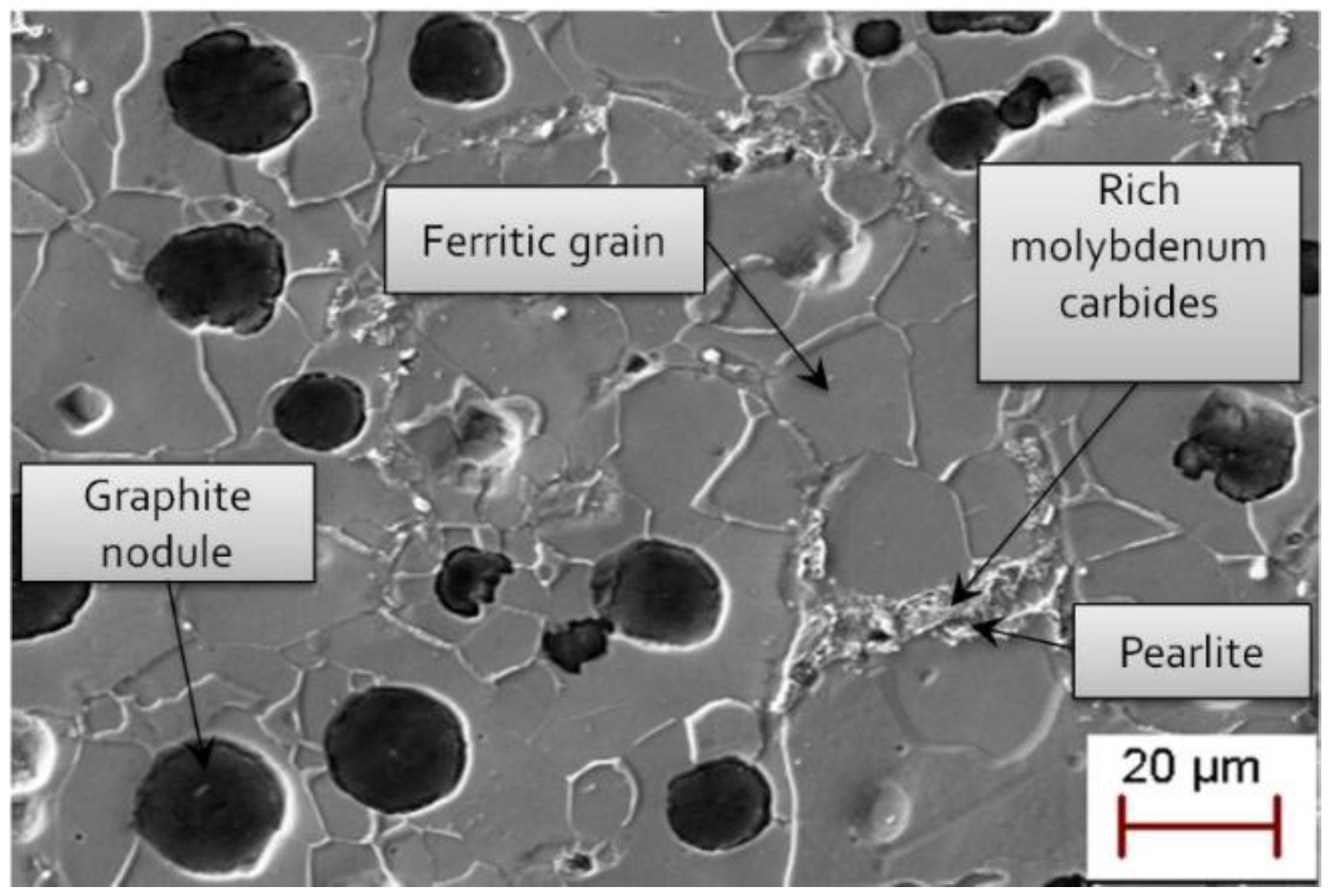
2.1. Material Properties

The material investigated is a ferritic (silicon, molybdenum) SiMo DCI with the chemical composition given in Table 1. Microstructural features were studied based on a previously detailed methodology [12,16]. Figure 1 shows the general microstructure observed by scanning electron microscopy (SEM, ZEISS Supra 55 EDS, Marly le Roi, France), which consists of graphite nodules surrounded by ferritic grains. These observations combined with energy dispersive spectrometry (EDS) enable one to obtain the mapping of the additional elements’ location. This highlighted that pearlite (about 10% on the surface) is located close to rich molybdenum carbide areas.
Table 1. Chemical composition in wt. % of the studied SiMo ductile cast iron (Fe: balance).
Compsition wt. %
SiCSMgMnCrMoSnCuP
4.243.000.0050.0280.2200.0700.6100.0090.0200.020
Figure 1. Typical initial microstructure of the studied ductile cast iron (DCI) (SEM observations).
Metals 05 02351 g001
Mean grain size and crystallographic texture were obtained by electron back-scattered diffraction (EBSD, ZEISS, Marly le Roi, France) on electropolished samples. Samples exhibit a weak crystallographic texture [16], and the ferritic grain size follows a normal distribution with a mean value equal to 16 μm and a standard deviation of 4.4 μm. Nodule geometrical parameters (i.e., surface fraction, mean size diameter and aspect ratio) were obtained thanks to a numerical treatment of surface images of polished samples using light microscopy (Olympus Europa, Hamburg, Germany) and SEM. The mean fraction graphite surface is 10.5%, in accordance with a volume fraction of 10.8% obtained by Archimedes’ balance measurements. The corresponding mean nodule equivalent diameter (i.e., the diameter of a circle with the same surface as the particle) is 12.6 ± 6.4 μm, and the nodule aspect ratio (i.e., the ratio between the major and the minor axis lengths) follows a normal distribution with an average value of 1.23 ± 0.35.

2.2. Mechanical Testing and Damage Analysis

Tensile and compression tests were carried out at different temperatures from RT up to 1073 K. Tensile samples are axisymmetric cylindrical dog bone shaped with 6 mm in diameter and 25 mm in gauge length. Compression samples are cylindrical with 5 mm in diameter (d0) and 5 mm in height (l0). Compression tests were performed in dry friction conditions involving a complex local stress and strain state with a severe barreling. A constant strain rate of 10−3 s−1 was used for both tensile and compression tests. During tensile tests, the temperature was controlled (±5 K) along the gauge length by a thermocouple, and the strain measurement was made by an alumina contact-type high temperature extensometer. During compression tests, the deformation along the axis of the sample was measured with a laser extensometer at room temperature and computed with the crosshead displacement for higher temperatures.
The damage mechanisms were analyzed using microstructural observations and quantitative measurements of the primary graphite dimensions. This approach is closely related to previous works [12,21,22], where mechanistically-based parameters were successfully used to quantify cavitation creep damage. After tensile and compression tests, samples were longitudinally cut and polished to measure the nodule parameters: surface fraction, mean size diameter and aspect ratio. These parameters were measured on the void created around the graphite nodules when debonding occurred and around the graphite nodules when they are severely damaged. Damage mechanisms were examined within the sample core, where the stress state is different from the sample surface [5,7,8].
Pictures of the microstructure were taken at low magnification along the specimen width, in the necking area close to the fracture in the mid-thickness of samples. These pictures were then analyzed in a region of interest (ROI) consisting of a rectangular zone of one millimeter in height moving from the fractured area to a homogeneous strain area corresponding to undamaged material. For each position of the ROI, the accumulated surfaces represented by voids are quantified, and so, void area fraction f values can be obtained in this way.
The equivalent plastic strain associated with the ROI is evaluated by the measurement of specimen cross-section at various distances to the fractured area [19], considering that the section remains circular. The average equivalent plastic strain over the cross-section εeq is estimated by the following relation (neglecting in the first approach macroscopic dilatation due to the existence of voids):
ε eq = ln ( A 0 A i )
A0 is the sample initial area in the transverse direction and Ai the sample mean transverse section where the deformation measurement is performed.

3. Experimental Results

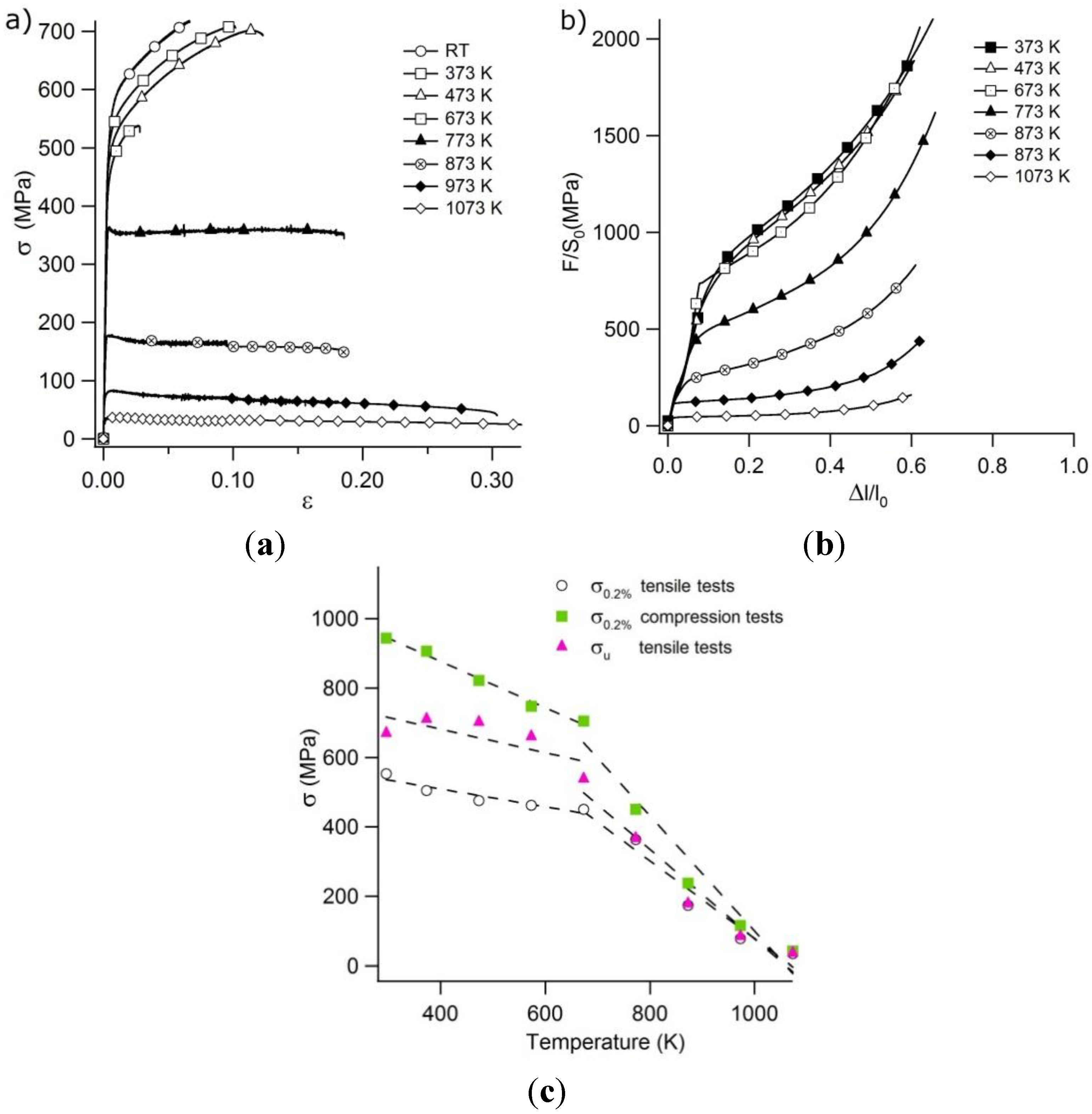
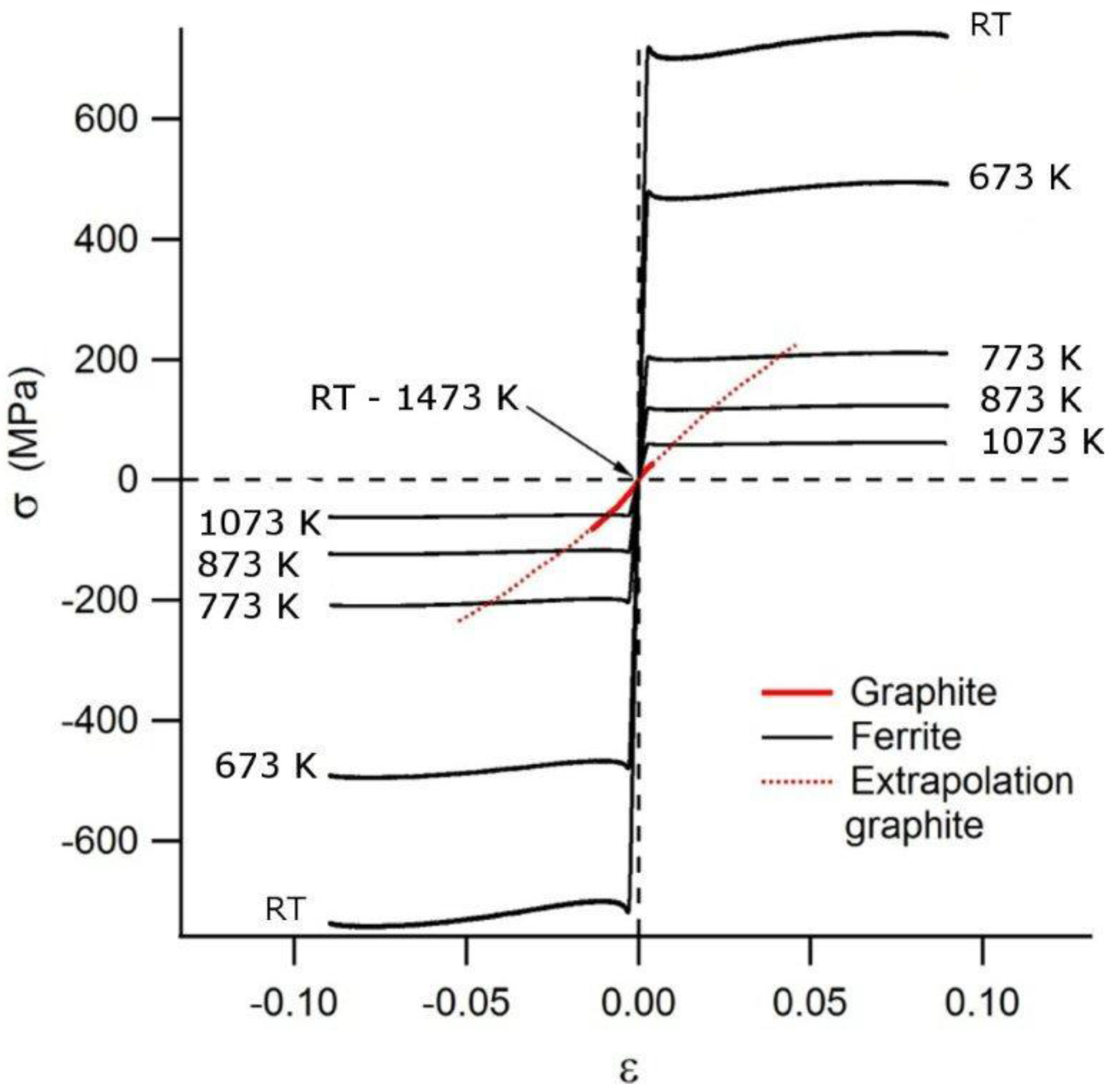
3.1. Tensile and Compression Behavior of the DCI with Temperature

Tensile and compression stress-strain curves are shown in Figure 2. Two distinct stages can be evidenced for both tension and compression solicitations, with a temperature of transition between 673 K and 773 K. The mechanical behavior in tension (Figure 2a) is weakly affected for temperatures lower than 673 K. From this temperature, mechanical properties (i.e., yield stress and ultimate stress) quickly decrease (Figure 2c). An important strengthening of DCI samples during the tensile test also occurs for temperatures in the range of 293 to 673 K. For higher temperatures, the plastic yielding occurs for a constant stress value, very close to the yield stress [12]. An embrittlement of the cast iron is also evidenced around a temperature of 673 K, corresponding to a strong decrease of the ultimate plastic strain level. This phenomenon was reported in several previous works and can be related to the local triaxial stress field inside the sample [23], the phosphorus segregation [24], the composition (silicon and carbon amount) [11] or the ageing by dynamic deformation [25].
Figure 2. (a) True monotonous tensile curves and (b) engineering compression curves as a function of the temperature. (c) Evolution of the conventional yield stress σ0.2 and the ultimate stress σu with the temperature.
Metals 05 02351 g002
Figure 2b displays the evolution of the mechanical properties with the temperature during compression tests. As for tensile experiments, the mechanical properties in compression strongly decrease when the temperature is higher than 673 K. Only engineering stress is represented due to the heterogeneous stress state inside the sample and the large dispersion on the strain measurement. A barreling effect is generated by the friction involved between the sample and the compression platens. Thus, the stress state is not uniaxial during compression tests. Furthermore, friction involves complex local stress and strain states, which are responsible for a hydrostatic pressure that closes the possible damage, which could occur in some regions of the sample between the soft graphite nodules and the ferritic matrix. This phenomenon allows a higher DCI strain under compression.

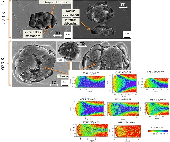
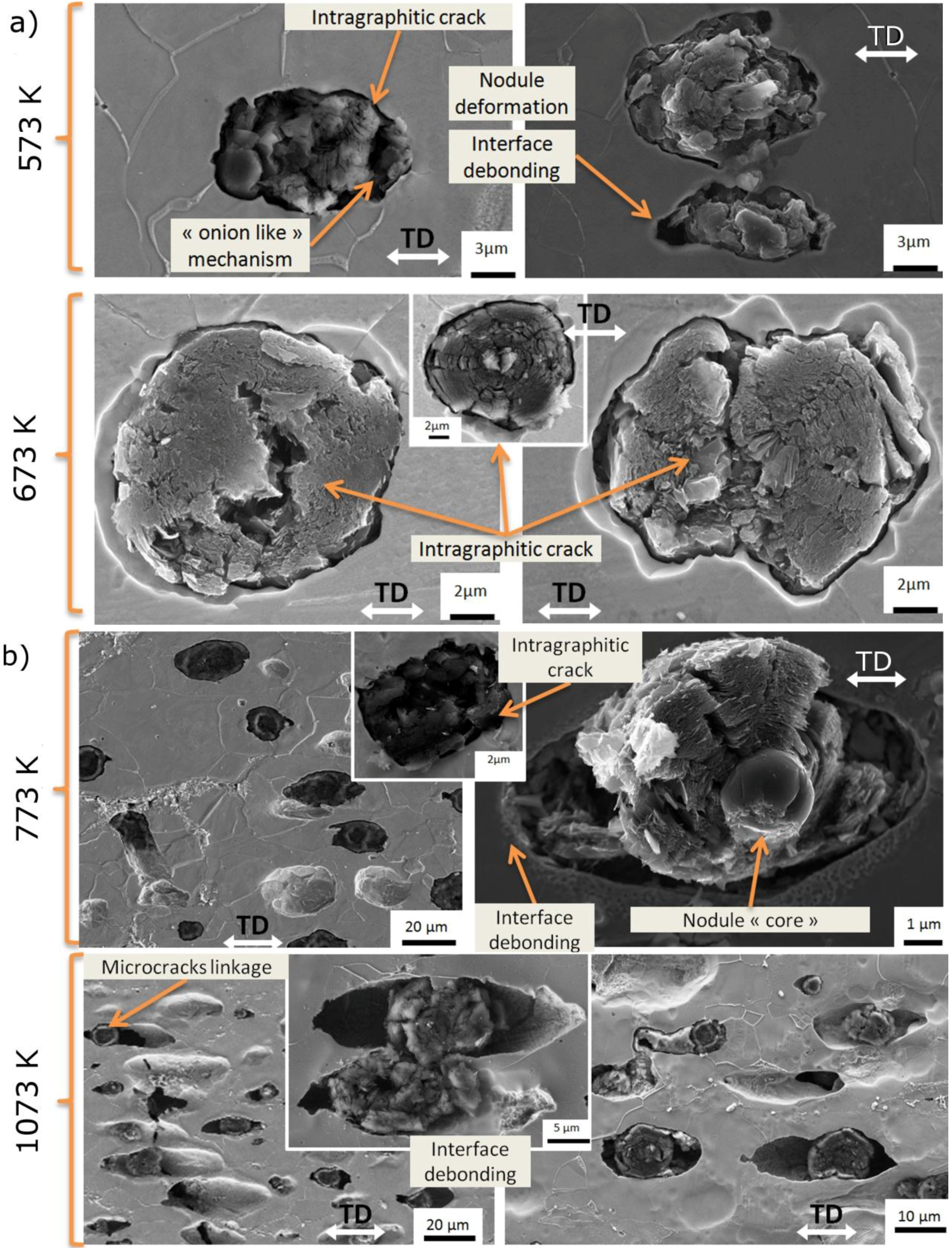
3.2. Evolution of the Damage Mechanisms with Temperature in Plastically-Deformed DCI

Figure 3a shows the damage mechanisms observed in samples deformed in tension mode for temperatures lower than 773 K. Observations were performed in the necking area. Damage mechanisms are identical to the ones previously identified at RT [26]: nodule plastic deformation with cracks and an onion-like mechanism related to nodules [7]. The latter consists of an internal debonding of graphite due to the difference of mechanical properties between the graphite core directly obtained from the melt and the carbon shield obtained by means of solid diffusion during cooling [27,28]. Debonding at the nodule/matrix interface rarely occurs for temperatures between RT and 673 K.
The evolution of the damage in tension for temperatures between 773 K and 1073 K is given in Figure 3b. The debonding at the nodule/matrix interface progressively becomes the predominant damage mechanism. Nodule deformation progressively decreases, and their shape remains almost spherical inside large cavities after the tensile test carried out at 1073 K. Voids coalescence can be observed for these temperatures. The viscoplastic behavior of DCI previously highlighted by Szmytka et al. [4] for temperatures higher than 773 K is confirmed in this work in terms of damage mechanism evolution.
Observations performed after compression tests carried out up to 673 K reveal that the ferritic grains are qualitatively deformed in the same way as graphite nodules (Figure 4a). In these pictures, the average plastic strain level εp = Δl/l0 along the sample symmetry axis is roughly constant, around 0.5. However, the strain repartition is not homogeneous, and several deformation levels are evidenced depending on the location within the specimen [16,26]. Deformation is maximal in the middle and in the corners of the samples. Faces in contact with compression platens are dead zones where the aspect ratio of nodules does not change. No voids are evidenced within or around the nodules, and no debonding is identified. Thus, up to 673 K, compressive deformation is characterized by the absence of voids in the material in accordance with the high negative stress triaxiality present in the center of the samples [16].
For temperature higher than 773 K, mechanical behavior in compression dramatically changes, since graphite nodules remain spherical while ferritic grains are severely deformed after large strain stages. This phenomenon is first observed on the sides and in the edge of compression samples for temperatures around 873 K. It becomes more pronounced and also occurs in the center of the specimens when the temperature increases up to 1073 K. At this temperature, the ferrite grains remain approximately unchanged in shape due to a possible recrystallization. The damage can be highlighted on the sample sides, as well as in the longitudinal plane, transverse to the stress direction (Figure 4b).
Figure 3. Typical damage mechanisms in tension for temperatures (a) lower than 673 K and (b) above 773 K after tensile tests (TD, tensile direction).
Metals 05 02351 g003
Figure 4. (a) Microstructures and damage after compression tests in the stress direction for temperatures of 573 K (εp = 0.40), 773 K (εp = 0.65), 873 K (εp = 0.56) and 1073 K (εp = 0.60). (b) Deformation and damage in the direction transverse to the stress direction after compression tests carried out at 873 K (εp = 0.56).
Metals 05 02351 g004

4. Quantification of the Damage Mechanisms in Plastically-Strained DCI at Various Temperatures

The mechanical behavior of our DCI was studied through tensile and compression tests carried out at temperatures between RT and 1073 K. Damage mechanisms and local deformations of the samples after testing were quantified, and the main results are given in this section. A thermomechanical interpretation is also proposed in order to understand the mechanical behavior and the damage mechanisms of the ductile iron with temperature.

4.1. Damage Evolution with Temperature during Monotonous Tensile Tests

The mechanical behavior becomes very viscous for temperatures starting from 773 K, in accordance with previous results [4]. This change has been qualitatively highlighted in terms of damage mechanisms in the last section. Figure 5 shows the variation of the equivalent diameter and the aspect ratio of nodules in the transverse and longitudinal planes near the fracture area (post-mortem measurements). In the transverse plane, these parameters remain constant and close to the values observed in the pristine material, independently of the temperature. In the longitudinal plane, they remain almost constant up to 673 K, and the values linearly increase above this temperature. The evolution of these parameters can be related to a significant microstructural change for temperatures higher than 673 K, revealing the material’s ability to coexist with the damage when the temperature increases. This explains the increase of the material ductility with the temperature.
Figure 5. Variation of (a) the aspect ratio and (b) the equivalent diameter of voids around graphite nodules with the temperature in the transverse and longitudinal planes, close to the fracture zone after tensile tests.
Metals 05 02351 g005
Figure 6 gives the evolution of the microstructural parameters as a function of the local equivalent plastic strain εeq (Equation (1)), for temperatures ranging between 293 K and 1073 K. The aspect ratio linearly evolves with the equivalent strain independently of the temperature (Figure 6a). The equivalent diameter presents one linear regime for temperatures between RT and 673 K, highlighted in the inset of Figure 6b, and two distinct linear regimes for temperatures higher than 673 K (Figure 6b). This result demonstrates the existence of a threshold equivalent plastic strain for which the damage evolution of the DCI markedly changes. The effect of the plastic deformation on the void area fraction f, for temperatures between RT and 1073 K, is shown in Figure 6c. f linearly increases with the plastic deformation for temperatures between RT and 673 K. However, above 673 K, two stages can be identified, as for the equivalent diameter evolution. In the first stage, f slightly increases with the deformation, and the second stage is related to a strong damage increase with the local plastic deformation. Several authors [20,29] consider the graphite fraction as a void volume fraction or as an initial damage, considering the weak mechanical properties of graphite, the facilities of debonding at the nodule/matrix interfaces and the damage inside the nodules at the beginning of the plastic deformation [8,29]. The critical debonding stress at the nodule/matrix interface has been evaluated at RT to be less than 80 MPa [5], which is a weak value in comparison to the yield stress. Thus, the void germination in our DCI samples can be neglected, in a similar way as previous works on high-strength steels [19]. In the following, f represents the growth of the voids around the damaged nodules.
Figure 6. Evolution of (a) the aspect ratio, (b) the equivalent diameter of voids around graphite nodules and (c) the void area fraction as a function of the equivalent plastic strain εeq, after tensile tests performed for temperatures ranging from RT to 1073 K (measurements in the longitudinal plane).
Metals 05 02351 g006

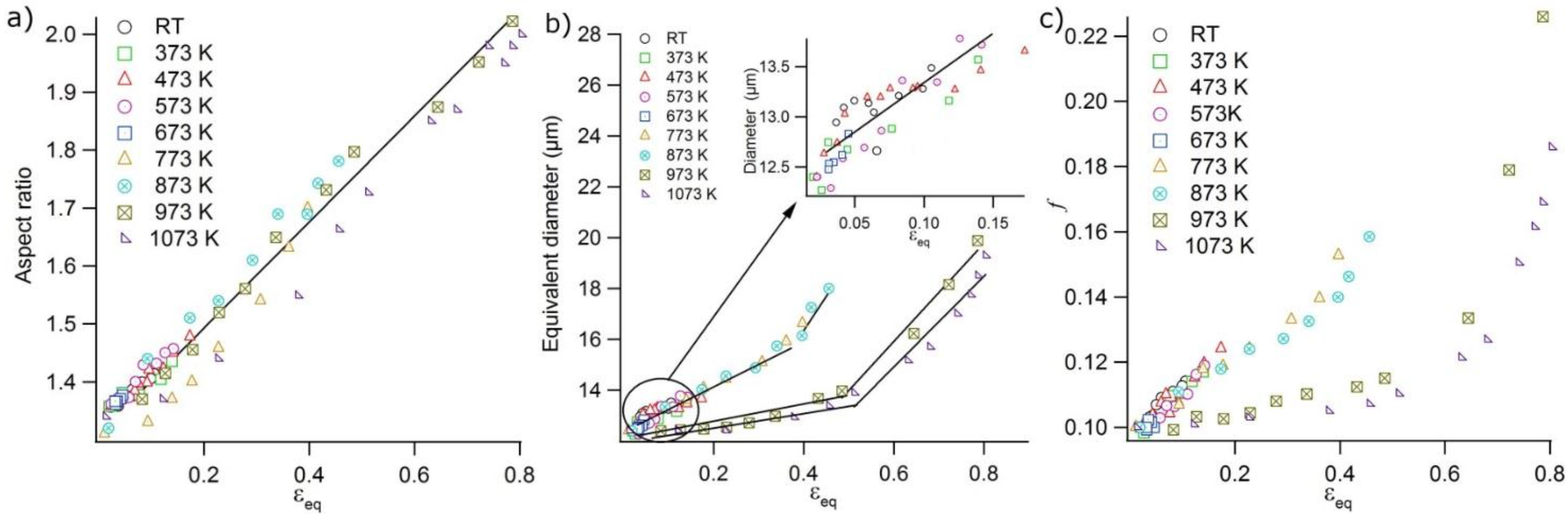
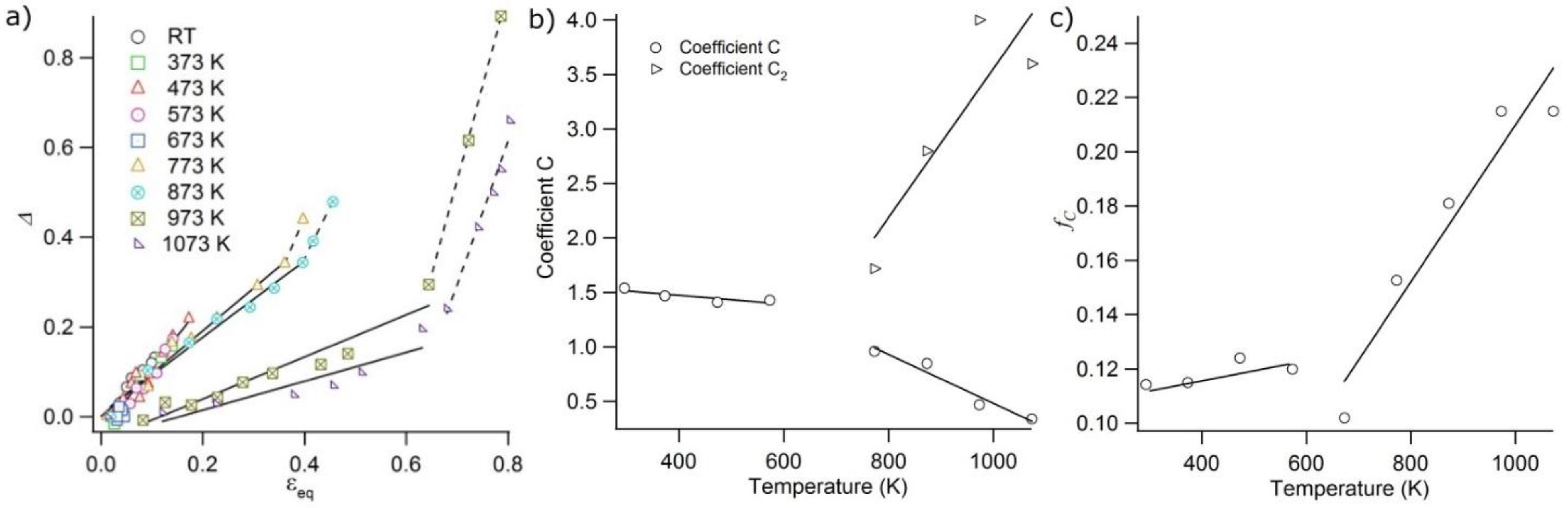
4.2. Void Growth Damage Model with Temperature for Monotonous Tensile Tested DCI

In order to predict the thermomechanical behavior and the final fracture of a material, it is necessary to establish an adequate model to describe the evolutional process of microstructural damage. In the case of DCI, this damage evolution can be conveniently described by several models. For instance, Dierickx [30] uses the Eshelby model [31] in order to study the critical debonding stress at the nodule/matrix interface. The Rice and Tracey model [32], which analyzes the growth of a single globular void in an infinitely rigid plastic body, is also often encountered [33,34] to describe the void growth in steels as a function of both strain and stress state. However, the Gurson model [35], describing the DCI damage, is the most currently used [5,20,29,36,37]. This model is able to capture continuous nucleation and growth of voids in cast irons, but few studies were focused on the impact of temperature.
In this work, the Gurson model modified by Tvergaard and Needleman [38] will be considered, following a previous work of Liu et al. [20] in which the void growth was investigated as a function of the deformation for DCI with different nodularity. In this model, the yield function ϕ takes the following form:
ϕ ( σ eq , σ y , f ) = ( σ eq σ y ) 2 + 2 f q 1 cosh ( 3 q 2 σ h 2 σ y ) 1 q 2 2 f 2 0
f is the void area fraction, σh is the mean normal stress, σeq is the traditional von Mises equivalent stress, σy is the yield stress and q1, q2 are material constants. In absence of any damage mechanisms, f = 0, and Equation (2) gives the well-known von Mises plasticity criterion.
In the following, the damage is considered as an isotropic scalar variable, which is expressed by the volume fraction rate f , including two distinct parts: nucleation ( f N ) and growing rate ( f G ):
f = f N + f G
Since f N can be neglected, the metal matrix is assumed to be incompressible, and f is linked to the equivalent plastic deformation εeq. Taking into account these hypothesis, Liu et al. [20] suggest the following void evolution relation:
f = 1 2 q 1 q 2 2 η ( 1 + ν ) f ( 1 f ) ε eq
This model considers the yielding condition and the interaction between voids through the parameters q1 and q2 introduced by Tvergaard and Needleman [38,39]. Poisson’s ratio ν and the stress triaxiality η (equal to 0.33 in the case of a smooth specimen) can be considered as constant values. This value depends only on the geometry of the specimen [20,33,34]. This allows defining a coefficient C, which represents the shape and distribution of the voids and the interactions between them:
C = 1 2 q 1 q 2 2 η ( 1 + ν )
Equation (4) can therefore be rewritten in a differential form as:
d f = C f ( 1 f ) d ε eq
A simple analytical model of void growth can therefore be obtained by integrating Equation (6) between the initial state (f0) and the current situation (f). This gives the following expression:
Δ = ln f ( 1 f 0 ) f 0 ( 1 f ) = C ε eq
This equation represents an incremental evolution law of the void volume growth as a function of the strain. The left side of Equation (7) is termed Δ in the following. It can be computed using the experimental values of f represented in Figure 6c (f0 is the initial void fraction and was taken as the initial graphite surface fraction of 10.5%).
Figure 7a shows the evolution of Δ as a function of the equivalent strain for temperatures between RT and 1073 K. Results are similar for temperatures ranging between RT and 673 K, and one single stage is demonstrated. C stands around a mean value of 1.5 (Figure 7b), slightly decreasing in this range of temperatures. For temperatures higher than 773 K, two distinct linear regimes can be demonstrated: an initial stage for which the slope C decreases as the temperature increases and a second stage in which the slope C2 strongly increases with temperature. C2 is a coefficient that represents the shape and distribution of the voids and the interactions between them in the necking area, where the voids’ coalescence occurs.
Figure 7. (a) Evolution of the parameter Δ of Equation (7) as a function of the equivalent strain for temperatures between RT and 1073 K. (b) Effect of temperature on C and C2 coefficients. (c) Evolution of the critical void fraction as a function of the temperature.
Metals 05 02351 g007
The evolution of C and C2 as a function of the temperature is shown in Figure 7b. Temperature has a significant effect on the C coefficient, which decreases as the temperature increases. C stands around a mean value of 1.5, slightly decreasing for temperatures lower than 673 K; from this temperature, C strongly decreases. According to Equation (5), the decrease of C with T corresponds to a decrease of η and ν. C2 takes higher values than C, reaching a value of four for higher temperatures. This can be correlated to the strong interaction between the voids in the coalescence area. The increase in temperature reduces the void growth rate, which allows an increase in ductility. However, in the necking region, the stress triaxiality η also increases. According to Equation (5), the evolution of C2 with temperature mostly represents an indirect measurement of the variation of η with T in the necking area.
During a tensile test, the void fraction f created around or inside the nodules increases until a critical value fc for which the fracture of the material occurs. Figure 7c shows the evolution of the critical void fraction for samples tested at various temperatures. fc was measured in a squared region of one millimeter square corresponding to the diameter of the specimen near the fracture surface. fc does not significantly change for low temperatures and reaches a value close to 0.12 to 0.13. These results are in good agreement with other studies reporting a critical void fraction of 0.16 at room temperature for DCI [20]. Tvergaard suggested that the value of fc can be taken as 0.15 [39], when the failure of ductile materials is induced by void coalescence. Moreover, fc is not only a material parameter, but depends on several factors as f0 or stress triaxiality. For instance, fc increases if f0 increases [40]. Our results show that for DCI, fc is also dependent on temperature when a critical value is reached. A noticeable decrease of fc can be observed at 673 K; indeed, at this temperature, samples present an embrittlement corresponding to a strong decrease of the ultimate plastic strain level [11,23,24,25]. For temperatures higher than 773 K, fc strongly increases with the temperature, which is directly connected to the increase of the C2 parameter. This underlines the increase in ductility of our DCI samples in tension for higher levels of temperature, associated with a better damage resistance.

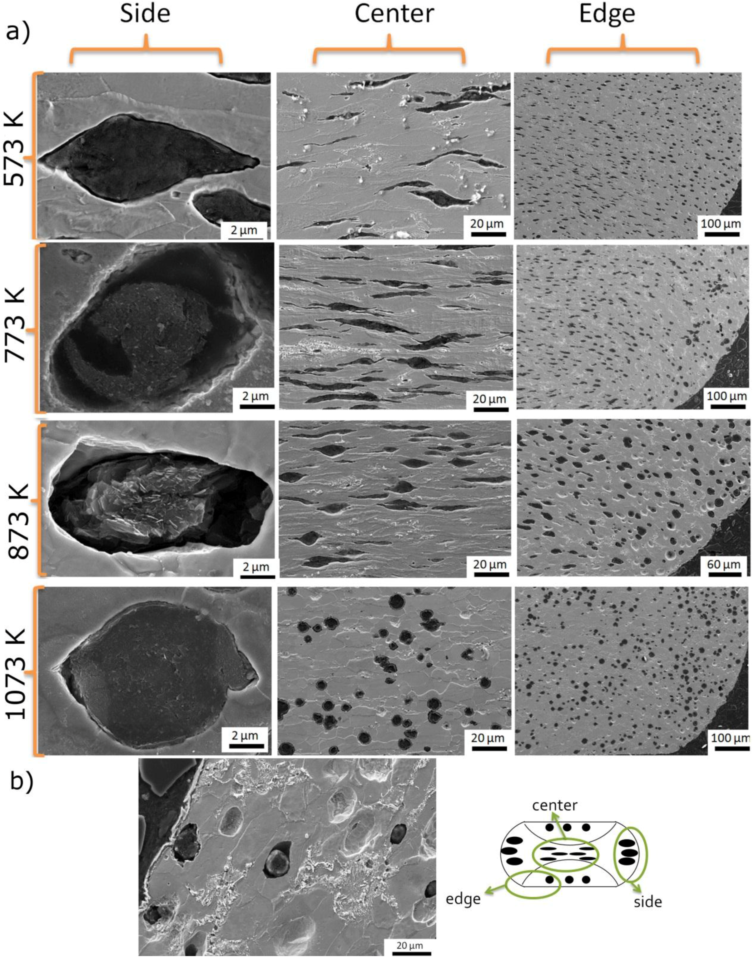
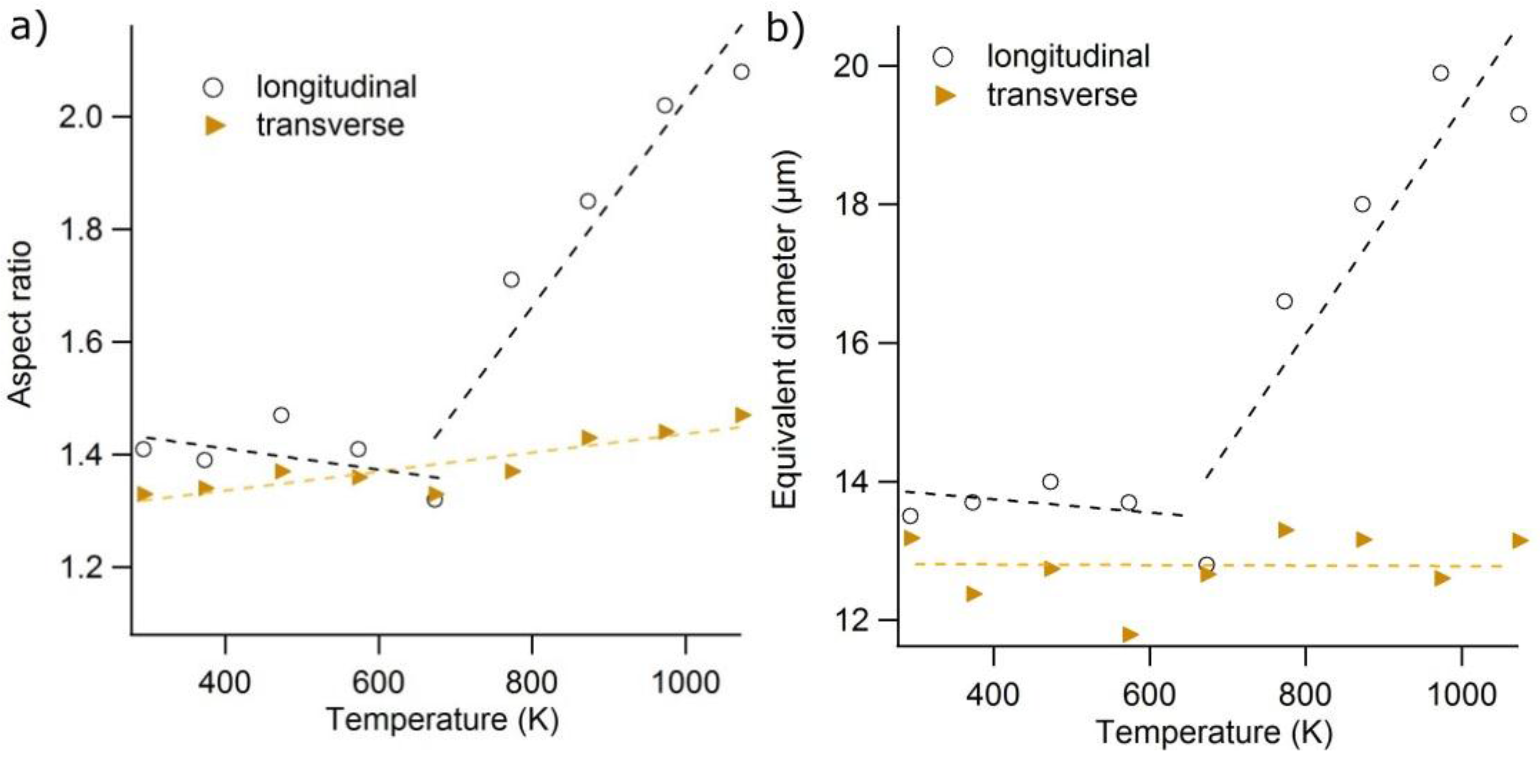
4.3. Nodule Deformation after Compression Tests with Temperature

The aspect ratio evolution of the graphite nodules was evaluated after compression tests carried out at temperatures from RT to 1073 K. Cartographies of this parameter through the thickness of samples plastically strained to values of εp in the range 0.4 to 0.7 were generated using a methodology previously described in detail [16]. The distribution of the aspect ratio inside the sample is not homogeneous (Figure 8). Maximal values are reached in the middle and at the corners of samples, which indicates a larger local strain level than εp.
Figure 8 shows that the temperature has a weak influence on the nodules’ deformation for temperatures lower than 773 K. The aspect ratio does not drastically change with temperature, and only the plastic strain seems to have a significant influence: the aspect ratio tends to increase with the plastic strain level. In this temperature range, the nodule aspect ratio appears to be a good indicator of the local deformation, generalizing our previous results performed at room temperature [16]. However, for temperatures higher than 773 K, a gradual homogenization of the aspect ratio distribution is depicted. This phenomenon is displayed in Figure 8 for εp = 0.66 ± 0.01 at temperature levels of 373 K, 773 K and 973 K. For the higher temperature 1073 K, the nodules are almost spherical in shape for a plastic deformation of εp = 0.60. It is known that the mechanical properties of the ferrite are strongly dependent on the temperature [41,42,43], unlike those of the graphite in this temperature range [44,45,46]. The yielding stress and the ultimate strength of the ferrite remain higher than those of graphite between RT and 773 K. Beyond this temperature, the difference between the mechanical properties of ferrite and graphite is reduced until the graphite properties become greater than the ferrite ones. This could explain the absence of the deformation of the graphite nodules at higher temperature levels.
Figure 8. Nodule aspect ratio mapping of the DCI samples compressed at several temperatures, for plastic strain values ranging around 0.4 to 0.7.
Metals 05 02351 g008

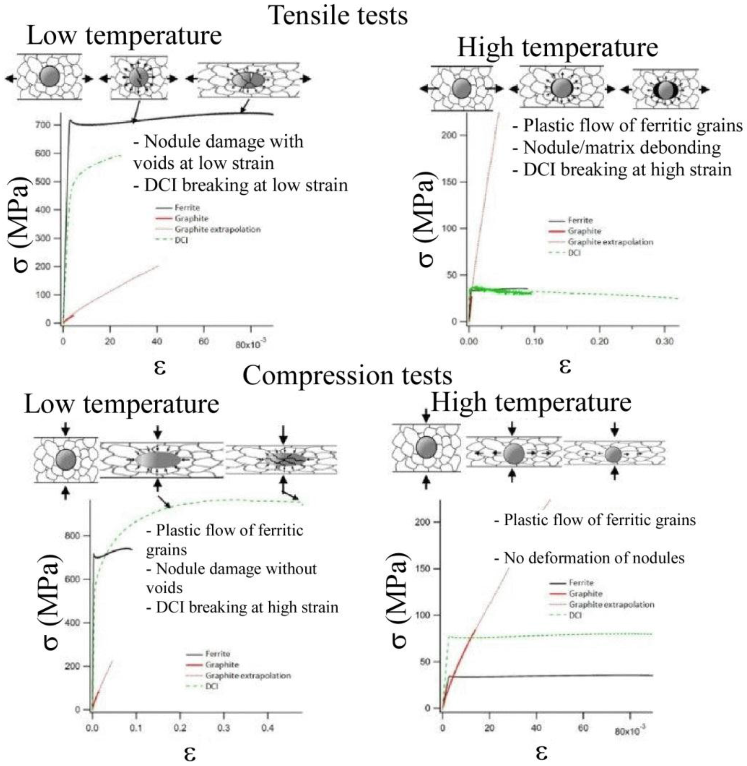
5. Synthesis of the Tension-Compression Damage Mechanisms as a Function of Temperature in Ferritic SiMo DCI

To conclude, an attempt at the synthesis of the main damage mechanisms is proposed in this section for ferritic DCI materials submitted to tension or compression strengths at different temperature levels. First, the typical mechanical behavior of a mild ferritic steel and graphite for tensile and compression tests carried out at low and high temperatures is schematically represented in Figure 9. In this graph, the mechanical properties of graphite nodules were assumed to be similar to those of polycrystalline graphite reported in the literature for a wide range of temperature [44,45,46]. An extrapolation of the corresponding graphite stress-strain curve is used to estimate the graphite mechanical properties for higher equivalent strain values. The typical tensile stress-strain curves of ferritic steels between RT and 1073 K are also shown. These curves are extrapolated considering previous works performed on ferritic steels [41,42,43] and silicon-iron alloys [47,48]. Second, Figure 10 gives a general overview of the DCI damage mechanisms under different thermomechanical loads, which can be deduced from our experimental results.
Figure 9. Schematic mechanical properties of the ferrite and graphite as a function of temperature (after data given in [41,42,43,44,45,46,47,48]).
Metals 05 02351 g009
For tensile tests monitored at room temperature, the mechanical properties of graphite and ferrite are very different. For a given strain level, the yield stress of ferrite occurs for levels much higher than elastic stresses present inside graphite. Therefore, the plastic deformation and work hardening of the ferrite matrix cannot be reached by the nodules, involving the development of a multiaxial stress state in their core. This causes the damage and the failure of the graphite in the early stages of the plastic deformation. When the temperature increases, the mechanical properties of the ferrite decrease while those of graphite remain constant (Figure 9). Thus, the incompatibility between the graphite and the ferrite behavior generates a critical stress that causes nodule/matrix debonding, instead of the fracture process inside the nodules. The void growth progressively takes place with the increase of the deformation (Figure 10).
Mechanical behavior is quite similar in compression and tension for temperature levels close to RT. The significant difference between the mechanical behavior of ferrite and graphite causes the nodule crushing by the ferritic matrix at the beginning of deformation. This results in damaged graphite nodules evidenced by the decrease of their mechanical properties [16]. Thus, the compression test coupled with friction existing between the samples and the platens involves a high hydrostatic pressure, closing the voids that could develop around the nodules. When the temperature increases, the graphite mechanical properties become no longer negligible. During the compression test, the plastic matrix flow occurs while graphite nodules still have an elastic behavior. Ferrite grains are plastically deformed, whereas graphite nodules remain spherical (Figure 10).
Figure 10. Overview of the damage mechanisms within and around graphite nodules. Low temperature refers to T < 673 K, typically. These mechanisms depend on the ferrite and the graphite mechanical properties, the temperature and the stress state (tensile and compression tests).
Metals 05 02351 g010

6. Conclusions

This paper brings new experimental results concerning the evolution with temperature of the mechanical properties of ductile cast irons. Tensile and compression tests were carried out in order to investigate the thermomechanical behavior of DCI samples for temperatures ranging from 293 K to 1073 K. The damage inside samples was analyzed using microstructural observations and quantitative measurements. Moreover, this damage evolution was successfully captured by a Gurson modified model quantifying the evolution of the void area fraction with the equivalent strain and temperature. The main results obtained in this study can be summarized by the following points:
  • The mechanical properties are weakly affected by temperatures lower than 773 K. For these temperatures, the main damage mechanisms in tension are nodule plastic deformation, cracks inside the nodules and onion-like mechanisms. No voids are evidenced after the compression test. For temperatures higher than 773 K, the debonding at the nodule/matrix interface becomes the predominant damage mechanism for tensile experiments. In the case of compressions tests, voids are evidenced around nodules.
  • The critical void fraction depends not only on f0, but also on the temperature. fc is weakly dependent on temperature for values below 773 K and strongly increases for higher levels of temperature.
  • After compression tests performed at low temperatures, nodules are crushed by the deformation of the ferritic matrix. Beyond this temperature, the graphite deformation decreases up to 1073 K. In the case of compression tests carried out for temperatures below 673 K, it is shown that the nodules’ strain can be used as a relevant parameter allowing the determination of the local strain level. For higher temperatures, the plastic matrix flow occurs around graphite nodules, which remain spherical in shape.
Finally, this paper proposes a synthesis of the DCI damage mechanisms under different thermomechanical loads, which can be deduced from our experimental results. This work can therefore be of interest in the case of the investigation of cast iron formability at high temperature.

Author Contributions

The paper is the result of a collaboration of all co-authors. I. Hervas performed this work during her PhD Thesis, under the supervision of E. Hug, PhD Director. I. Hervas, A. Thuault and E. Hug equally contribute to the study of the experimental results, the scientific discussion and the redaction of the article.

Conflicts of Interest

The authors declare no conflict of interest.

References

  1. Szmytka, F.; Michaud, P.; Rémy, L.; Köster, A. Thermo-mechanical fatigue resistance characterization and materials ranking from heat-flux-controlled tests. Application to cast-irons for automotive exhaust parts. Int. J. Fatigue 2013, 55, 136–146. [Google Scholar] [CrossRef]
  2. Guillemer-Neel, C.; Bobet, V.; Clavel, M. Cyclic deformation behaviour and bauschinger effect in ductile cast iron. Mater. Sci. Eng. A 1999, 272, 431–442. [Google Scholar] [CrossRef]
  3. Nadot, Y.; Mendez, J.; Ranganathan, N. Influence of casting defects on the fatigue limit of nodular cast iron. Int. J. Fatigue 2004, 26, 311–319. [Google Scholar] [CrossRef]
  4. Szmytka, F.; Rémy, L.; Maitournam, H.; Köster, A.; Bourgeois, M. New flow rules in elasto-viscoplastic constitutive models for spheroïdal graphite cast-iron. Int. J. Plast. 2010, 26, 905–924. [Google Scholar] [CrossRef]
  5. Dong, M.J.; Prioul, C.; François, D. Damage effect on the fracture toughness of nodular cast iron: Part I. Damage characterization and plastic flow modeling. Metall. Mater. Trans. A 1997, 28, 2245–2254. [Google Scholar] [CrossRef]
  6. Dai, P.Q.; He, Z.R.; Zheng, C.M.; Mao, Z.Y. In situ SEM observation on the fracture of austempered ductile cast iron. Mater. Sci. Eng. A 2001, 319–321, 531–534. [Google Scholar] [CrossRef]
  7. Di Cocco, V.; Iacoviello, F.; Cavallini, M. Damaging micromechanisms characterization of a ferritic ductile cast iron. Eng. Fract. Mech. 2010, 77, 2016–2023. [Google Scholar] [CrossRef]
  8. Iacoviello, F.; di Bartolomeo, O.; di Cocco, V.; Piacente, V. Damaging micromechanisms in ferritic-pearlitic ductile cast irons. Mater. Sci. Eng. A 2008, 478, 181–186. [Google Scholar] [CrossRef]
  9. Liu, J.H.; Li, G.L.; Liu, G.S.; Hao, X.Y. Damaged evaluation of ferrite ductile iron with electric resistance. Mater. Lett. 2004, 58, 1051–1055. [Google Scholar] [CrossRef]
  10. Liu, J.H.; Li, G.L.; Hao, X.Y.; Zeng, D.B.; Sun, Z.H. Ultrasonic measurement of fatigue damage of nodular cast iron. Mater. Lett. 2001, 50, 194–198. [Google Scholar] [CrossRef]
  11. Yanagisawa, O.; Lui, T.S. Influence of the structure on the 673 K embrittlement of ferritic spheroidal graphite cast iron. Trans. Jap. Inst. Met. 1983, 24, 858–867. [Google Scholar] [CrossRef]
  12. Hug, E.; Keller, C.; Favergeon, J.; Dawi, K. Application of the monkman-grant law to the creep fracture of nodular cast irons with various matrix compositions and structures. Mater. Sci. Eng. A 2009, 518, 65–75. [Google Scholar] [CrossRef]
  13. Balos, S.; Sidjanin, L. Microdeformation of soft particles in metal matrix composites. J. Mater. Process. Technol. 2009, 209, 482–487. [Google Scholar] [CrossRef]
  14. Ghaderi, A.R.; Ahmadabadi, M.N.; Ghasemi, H.M. Effect of graphite morphologies on the tribological behavior of austempered cast iron. Wear 2003, 255, 410–416. [Google Scholar] [CrossRef]
  15. He, Z.R.; Lin, G.X.; Ji, S. Deformation and fracture of cast iron with an optimized microstructure. Mater. Charact. 1997, 38, 251–258. [Google Scholar]
  16. Hervas, I.; Bettaieb, M.B.; Thuault, A.; Hug, E. Graphite nodule morphology as an indicator of the local complex strain state in ductile cast iron. Mater. Des. 2013, 52, 524–532. [Google Scholar] [CrossRef]
  17. Shi, J.; Savas, M.A.; Smith, R.W. Plastic deformation of a model material containing soft spheroidal inclusions: Spheroidal graphite cast iron. J. Mater. Process. Technol. 2003, 133, 297–303. [Google Scholar] [CrossRef]
  18. Qi, K.; Yu, F.; Bai, F.; Yan, Z.; Wang, Z.; Li, T. Research on the hot deformation behavior and graphite morphology of spheroidal graphite cast iron at high strain rate. Mater. Des. 2009, 30, 4511–4515. [Google Scholar] [CrossRef]
  19. Hug, E.; Martinez, M.; Chottin, J. Temperature and stress state influence on void evolution in a high-strength dual-phase steel. Mater. Sci. Eng. A 2015, 626, 286–295. [Google Scholar] [CrossRef]
  20. Liu, J.H.; Hao, X.Y.; Li, G.L.; Liu, G.S. Microvoid evaluation of ferrite ductile iron under strain. Mater. Lett. 2002, 56, 748–755. [Google Scholar] [CrossRef]
  21. Eggeler, G. Microstructural parameters for creep damage quantification. Acta Metall. Mater. 1991, 39, 221–231. [Google Scholar] [CrossRef]
  22. Eggeler, G.; Earthman, J.C.; Nilsvang, N.; Ilschner, B. Microstructural study of creep rupture in a 12% chromium ferritic steel. Acta Metall. 1989, 37, 49–60. [Google Scholar] [CrossRef]
  23. Chao, C.G.; Lui, T.S.; Hon, M.H. The effect of triaxial stress field on intermediate temperature embrittlement of ferritic spheroidal graphite cast irons. Metall. Mater. Trans. A 1988, 19, 1213–1219. [Google Scholar] [CrossRef]
  24. Chen, S.F.; Lui, T.S.; Chen, L.H. The effect of phosphorous segregation on the intermediate temperature embrittlement of ferritic spheroidal cast irons. Metall. Mater. Trans. A 1994, 25, 557–561. [Google Scholar] [CrossRef]
  25. Yanagisawa, O.; Lui, T.S. Effect of carbon content and ferrite grain size on the tensile flow stress of ferritic spheroidal graphite cast iron. Metall. Mater. Trans. A 1985, 16, 667–673. [Google Scholar] [CrossRef]
  26. Hervas, I.; Bettaieb, M.B.; Hug, E. Damage mechanisms evolution of ductile cast irons under thermomechanical loadings. Int. J. Mater. Prod. Technol. 2013, 47, 23–32. [Google Scholar] [CrossRef]
  27. Lacaze, J.; Castro, M.; Lesoult, G. Solidification of spheroidal graphite cast irons—II. Numerical simulation. Acta Mater. 1998, 46, 997–1010. [Google Scholar] [CrossRef]
  28. Lesoult, G.; Castro, M.; Lacaze, J. Solidification of spheroidal graphite cast irons—I. Physical modelling. Acta Mater. 1998, 46, 983–995. [Google Scholar] [CrossRef]
  29. Berdin, C.; Dong, M.J.; Prioul, C. Local approach of damage and fracture toughness for nodular cast iron. Eng. Fract. Mech. 2001, 68, 1107–1117. [Google Scholar] [CrossRef]
  30. Dierickx, P. Etude de la microstructure et des mécanismes d’endommagement de fontes gs ductiles. Influence des traitements thermiques de ferritisation. Ph.D. Thesis, INSA de Lyon, Lyon, France, October, 1996. [Google Scholar]
  31. Eshelby, J.D. The determination of the elastic field of an ellipsoidal inclusion and related problems. Proc. A 1957, 241, 376–396. [Google Scholar] [CrossRef]
  32. Rice, J.R.; Tracey, D.M. On the ductile enlargement of voids in triaxial stress fields. J. Mech. Phys. Solids 1969, 17, 201–217. [Google Scholar] [CrossRef]
  33. Chae, D.; Koss, D.A. Damage accumulation and failure of HSLA-100 steel. Mater. Sci. Eng. A 2004, 366, 299–309. [Google Scholar] [CrossRef]
  34. Jablokov, V.; Goto, D.; Koss, D. Damage accumulation and failure of HY-100 steel. Metall. Mater. Trans. A 2001, 32, 2985–2994. [Google Scholar] [CrossRef]
  35. Gurson, A.L. Continuum theory of ductile rupture by void nucleation and growth. Part I—Yield criteria and flow rules for porous ductile media. J. Eng. Mater. Technol. 1977, 99, 2–15. [Google Scholar] [CrossRef]
  36. Guillemer-Neel, C.; Feaugas, X.; Clavel, M. Mechanical behavior and damage kinetics in nodular cast iron: Part II. Hardening and damage. Metall. Mater. Trans. A 2000, 31, 3075–3085. [Google Scholar] [CrossRef]
  37. Zhang, K.S.; Bai, J.B.; Francois, D. Ductile fracture of materials with high void volume fraction. Int. J. Solids Struct. 1999, 36, 3407–3425. [Google Scholar] [CrossRef]
  38. Tvergaard, V.; Needleman, A. Analysis of the cup-cone fracture in a round tensil bar. Acta Metall. 1984, 32, 157–169. [Google Scholar] [CrossRef]
  39. Tvergaard, V. Material failure by void coalescence in localized shear bands. Int. J. Solids Struct. 1982, 18, 659–672. [Google Scholar] [CrossRef]
  40. Benseddiq, N.; Imad, A. A ductile fracture analysis using a local damage model. Int. J. Press. Vessel. Pip. 2008, 85, 219–227. [Google Scholar] [CrossRef]
  41. Brnic, J.; Turkalj, G.; Krscanski, S.; Lanc, D.; Canadija, M.; Brcic, M. Information relevant for the design of structure: Ferritic—Heat resistant high chromium steel X10CrAlSi25. Mater. Des. 2014, 63, 508–518. [Google Scholar] [CrossRef]
  42. Chiu, Y.-T.; Lin, C.-K.; Wu, J.-C. High-temperature tensile and creep properties of a ferritic stainless steel for interconnect in solid oxide fuel cell. J. Power Sources 2011, 196, 2005–2012. [Google Scholar] [CrossRef]
  43. Steckmeyer, A.; Rodrigo, V.H.; Gentzbittel, J.M.; Rabeau, V.; Fournier, B. Tensile anisotropy and creep properties of a Fe–14CrWTi ODS ferritic steel. J. Nucl. Mater. 2012, 426, 182–188. [Google Scholar] [CrossRef]
  44. Gillin, L.M. Deformation characteristics of nuclear grade graphites. J. Nucl. Mater. 1967, 23, 280–288. [Google Scholar] [CrossRef]
  45. Malmstrom, C.; Keen, R.; Green, L. Some mechanical properties of graphite at elevated temperatures. J. Appl. Phys. 1951, 22, 593–600. [Google Scholar] [CrossRef]
  46. Yoda, S.; Eto, M. The tensile deformation behavior of nuclear-grade isotropic graphite posterior to hydrostatic loading. J. Nucl. Mater. 1983, 118, 214–219. [Google Scholar] [CrossRef]
  47. Hug, E.; Hubert, O.; Clavel, M. Some aspects of the magnetomechanical coupling in the strengthening of nonoriented and grain-oriented 3% SiFe alloys. IEEE Trans. Magn. 1997, 33, 763–771. [Google Scholar] [CrossRef]
  48. Hug, E.; Hubert, O.; Houtte, J.J.V. Effect of internal stresses on the magnetic properties of non-oriented Fe-3 wt. % Si and (Fe,Co)-2 wt. % V alloys. Mater. Sci. Eng. A 2002, 332, 193–202. [Google Scholar] [CrossRef]

