
Hydrogen Solid State Storage on MgH2 Compacts for Mass Applications


1
Institute Néel, CNRS & Université Grenoble Alpes, CEDEX 9, 38042 Grenoble, France
2
JOMI-LEMAN SA, 1115 Route de St Thomas, 26190 La Motte Fanjas, France
*
Author to whom correspondence should be addressed.
Metals 2023, 13(5), 992; https://doi.org/10.3390/met13050992
Submission received: 28 March 2023
/
Revised: 3 May 2023
/
Accepted: 12 May 2023
/
Published: 20 May 2023
Abstract
:The mass storage of hydrogen is a challenge considering large industrial applications and continuous distribution, e.g., for domestic use as a future energy carrier that respects the environment. For a long time, molecular hydrogen was stored and distributed, either as a gas (pressurized up to 75 MPa) or as a cryogenic liquid (20.4 K). Furthermore, the atomic storage of hydrogen in the solid-state form via metallic or covalent compounds is still the subject of intense research and limited to a small scale for some practical developments. In addition, other type H chemical storage routes are being tested, such as ammonia and LOHC (Liquid Organic Hydrogen Carrier), etc. In any case, the main constraint remains security. However, Hydrogen Solid State Storage (HSSS) using MgH2 bodies has been shown to be feasible in terms of process and safety. Furthermore, its intrinsic volumetric densification was proven to be much better performing with 106:70:45 kgH2/m3 for solid (RT):LH (20.4 K):gas (75 MPa), respectively. Very early on, fairly reactive MgH2-based pellets were produced (for max. ~27 tons/year) at McPhy Energy using a series of unique and self-built installations. Thus, the design of large instrumented reservoirs was undertaken thanks to fundamental research first carried out at the CNRS. So, prototypes of storage units from 100 to ~5500 kWh have been produced. However, McPhy took other routes a few years ago (smelting and refueling stations) because the HSSS market was not merging at that time. Today, a new operator, Jomi–Leman, therefore, decided to try the challenge again focusing on applications with on-site production and mass HSSS.
1. Introduction
HSSS using MgH2 offers the best H absorption performance at 7.6 wt% H of all reversible metal hydrides. For times and reference to many publications, the initially low reactive Mg metal can be markedly activated using one, or better both, procedures such as 1—Severe Plastic Deformation (SPD) methods such as the most widely used HEBM (High Energy Ball Milling) [1,2,3,4,5,6] or HPT (High Pressure Torsion) [7,8,9], ECAP (Equal Channel Angular Pressing) [10,11,12], intensive rolling [13,14], and 2—combine with various additives as catalysts to stimulate hydrogen sorption, e.g., in Refs [15,16,17,18,19] among hundreds. All the treatments lead to reducing the particles/crystallites to micro/nanometric sizes, to develop high densities of microstructural defects, and just as much to deliver nucleation centers. Obviously, this must be undertaken on MgH2 (pre-hydrogenated particles) since Mg is a ductile metal, unlike its hydride which is very brittle. Then, the two operations—1 and 2—are mandatory to provide high kinetics to the absorption/desorption (A/D) processes. Previously, this was launched to scale up anS process as described in Ref. [20]. If the H to Mg reaction proceeds rapidly at a sufficiently high temperature (>300 °C), it corresponds to a large heat of formation of ~74 kJ/mole. This is equivalent to ~33 kWh of energy, or in other terms, ~1/3 of the combustion energy for 1 mol. H2. These are almost significantly large quantities, so the principles of advanced mass HSSS technologies using MgH2 must take these values into account in order to provide efficient and effective storage units. Considerations for efficient heat transfer based on various storage designs have already been proposed in Ref. [21]. These consisted of developing either heat transfer properties within the compacted powder as indicated Refs. [22,23], or externalizing the heat of the reaction (exothermic/endothermic) either reversibly as mentioned Ref. [24], or via fluid exchangers as proposed in Refs. [25,26], e.g., for energy regeneration or even for heating purposes as suggested in Ref. [27]. Thus, the reservoirs containing stacks of MgH2-based bodies must have well-suited designs, as cited in Ref. [28].
2. Materials Main Characteristics
From the selected sizes (40 to 120 µm) of commercial granules of pure Mg (>95.5% purity), a first hydrogenation was carried out. Typically, it was made under 2–3 MPa at T >360 °C to deliver primary powders of MgH2. This operation takes time (4–5 h) because the MgH2 layers form on the surface of the grains according to a contracting envelope model [29]. Within such layers, the diffusion process is extremely weak, from 10−14 to 10−20 m2 s−1 at ~20 °C to ~580 °C, respectively [30]. The next step was to transform the primary powder into fast A/D reactions. Using HEBM, fragile MgH2 powder added with selected additives called catalysts was processed by HEBM for a grain size reduction to a few µm and a crystallite size to a few nm. At the same time, a high defect density, namely with dislocations to cracks, was developed so that a nucleation growth model process applies and explains the very rapid sorption reactions that were observed in Refs. [31,32]. From the literature, it was shown that a very wide panel of activation additives have been already proposed, from metals and alloys to specific oxides, halides, and much more, as cited in Ref. [33].
3. Scaling the Materials Production
3.1. Mass Production of Primary MgH2
The in-lab MgH2 production was at a few tens of grams per batch. The production of primary MgH2 powders at the factory scale was made using home-designed furnaces (SATIL, Chambéry, France) to process in similar conditions (~300 °C under 3–4 MPa H2 pressure) as large as 50 kg batch of Mg granules per furnace. So, rotating furnaces as shown in Figure 1 allows delivery of a homogenized MgH2 product with up to ~98% purity. However, this hydride in the form of granules (a few tens µm size) still exhibits a slow reactivity even after several H/D cycles. The production of MgH2 in the laboratory was a few tens of grams per batch.
3.2. Conventional Nano-Structuration with Additives
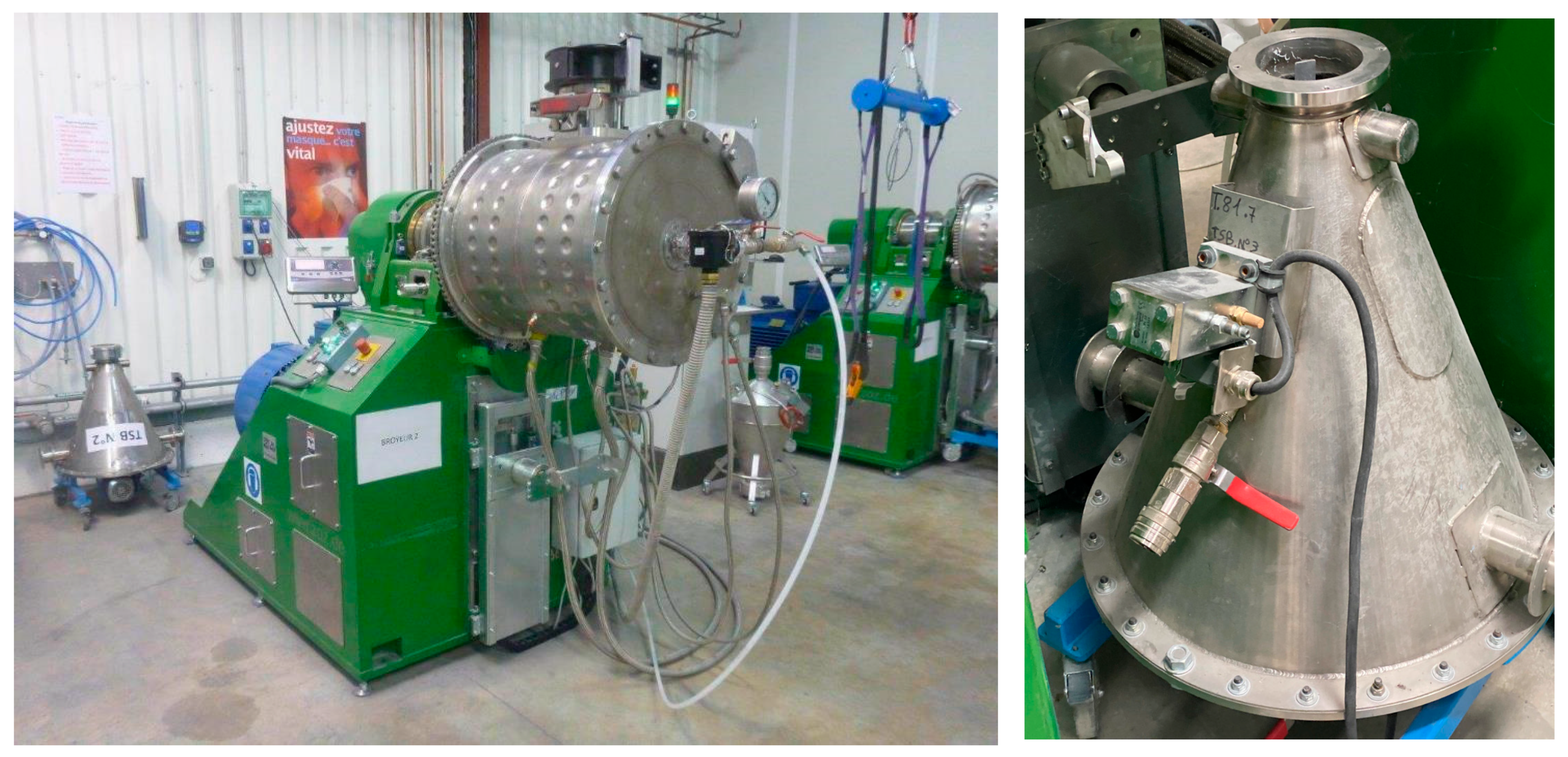
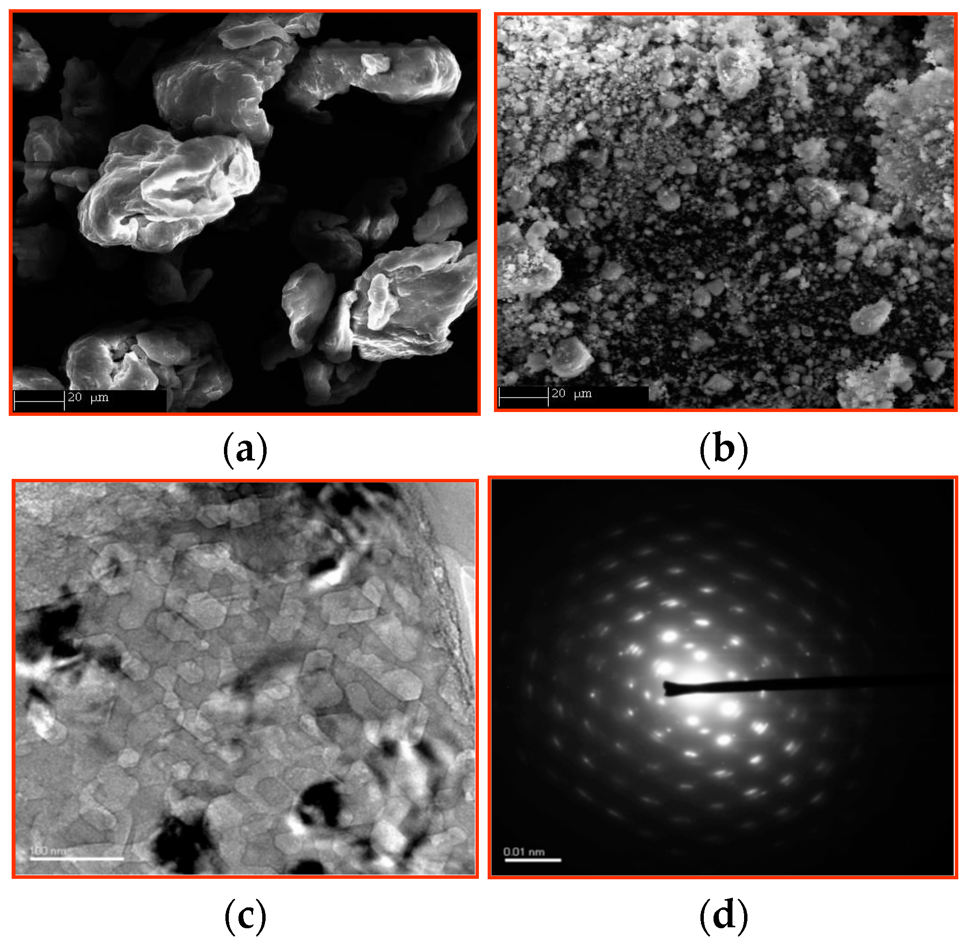
The primary MgH2 granules in an amount of approximately 20 kg per batch were then HEBM-treated using a large industrial ball-miller (Zoz-GmbH, Wenden, Germany) as shown in Figure 2. This considerably reduces the dimensions of the particles to µm sizes and of the crystallites to a few tens of nm size, as illustrated by the SEM and TEM pictures shown in Figure 3. In parallel with this intense mechanical treatment carried out for about 5 h, a large density of defects settles in the grains thanks to the fragile characteristics of the hydrogenated material.
The additive material was chosen from among the many well-known active additives, being either of the metal-type (alloys based on d-metal such as Ti, V, etc.) or non-metal materials (oxides of d-metal, better from VA column of the Periodic Table). Batches of the first type of additives were readily prepared by high frequency induction using the melting facilities (EFD SA, Seyssinet, France) as shown in Figure 4. It was noticed that depending on the ductility/brittleness of the additives, subsequent impacts on micro-structuring and defects created due to abrasion effects can be observed later in terms of better kinetics H-sorption.
So, the severe plastic deformation procedure undertaken by HEBM on the mixture of MgH2 and additive leads deliver relatively fast A/D reactive MgH2. Figure 5 displays the kinetics of absorption at different temperatures as measured using a Sievert-type pressure–composition–temperature (PCT) set-up.
3.3. SPD Route from Alloys and Composites
Presently, a novel micro-structuration route is under development based on the severe plastic deformation by fast forging bulk samples of specifically formulated Mg-rich compounds [34,35,36]. This will allow less time and less energy consumption, namely the comparison made with the HEBM process. As a consequence, implementation of the production will be made under safer procedures. Figure 6 shows the A/D sorption traces of forged Mg-based materials when undertaken at the lab-scale as shown in Ref. [37].
3.4. Heat Transfer Improvements
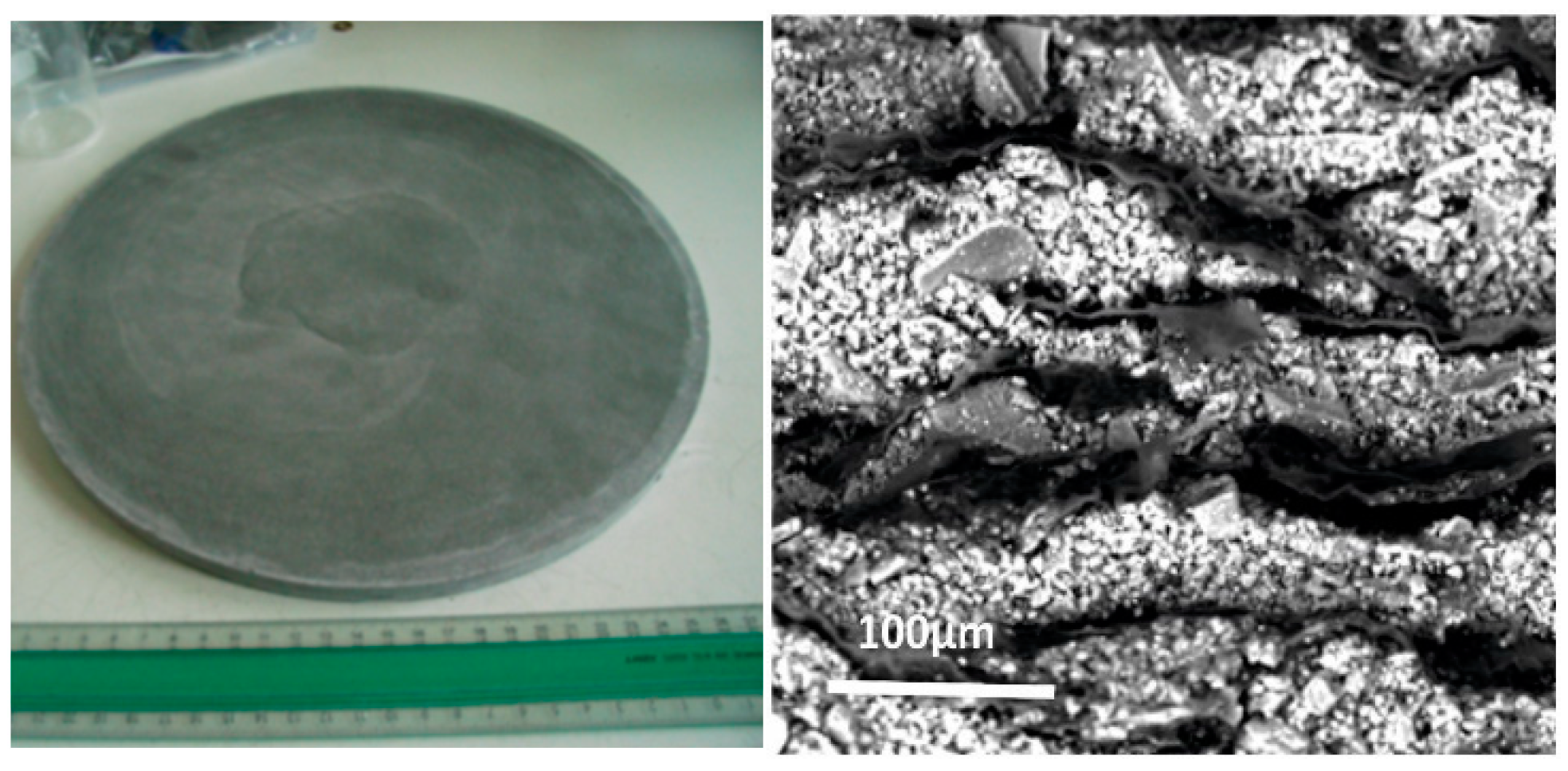
Since to the H ↔ Mg reactions corresponds a heat of formation of ~74 kJ/mole, the progress of the reactions is immediately governed by the capacity of the reacting bed to transfer heat according to the exothermic or endothermic process. Following the extensive knowledge acquired very early on at the Néel Institute [23], a certain volume of natural expanded graphite (NEG) was added to the activated MgH2-based powder. The proportion of NEG to hydride was defined ranging from 7 to 15 vol. % to determine the efficiency of a slow or a fast heat transfer. A compacted disc 30 cm in diameter, as shown in Figure 7, for ~1 cm thick composite (MgH2 + additive + NEG) was pressed under ~1 ton/cm2. Therefore, its final volume is about 1 L and its mass is about 1 kg, so contains up to 650 N-liters of hydrogen. In terms of density, the HSSS realized under normal conditions is equivalent to that of pressurized H2 gas under 650 bars.
In fact, such a disc exhibits sufficiently large practical porosity to hydrogen [38,39] since the determined reaction kinetics were quite similar to that of a loose powder sample. The radial thermal conductivity was also found to be ~30 times that measured on a similarly compressed disc but without the NEG particles, as the ribbon shape of particles leads to a radial alignment. Nevertheless, the axial thermal conductivity was improved only about five times [23,40]. Due to the good compactness of the disc, no visible reaction occurs when it is aired on a table, unlike the free MgH2 powder fresh from the HEBM process, which is highly pyrophoric.
4. Tanks for Applications
Series of ~100 compacted discs, for approximately 5 to 6 kg of solid hydrogen, were stacked in specific stainless-steel tubes. This was made using an in-house installer which allows operation under an Ar gas atmosphere, to alternate the discs and high thermal conductivity metal fins. As said above, the heat transfer at the absorption/desorption reactions directly monitors the flow of H2 (absorption under ~10 MPa)/desorption under ~2–3 MPa H2 pressure) from the reservoir. Thus, in order to optimize the heat transfers, two solutions were developed; either that the heat of reaction is definitively transferred out of the hydrogen storage unit or stored aside to be soon reused.
4.1. External Exchange-Type Tank
The design of the external exchange is classic because it was often proposed in the literature for different metal hydride tanks. It involves extracting or supplying heat using pipes carrying fluid out or into the reservoir where coolers or heaters are installed within the hydride mass and then controlled on demand. From a large panel of articles, many solutions have already been proposed for MgH2-based tanks depending on the size, the mass, and the types of configurations.
Due to the rather high temperature (~300–350 °C) where both hydrogenation/dehydrogenation processes occur at fast enough rates, a good enough thermal conductivity oil was used to transfer the heat. Thus, a running time as short as 3–4 h can be exploited, depending on the oil flow and indeed the heat transfer surface of the exchanger tubes. If care is not taken, thermal energy will be lost, however, regenerative solutions can be arranged. For example, in a large enough plant where many tanks are loaded parallel, the reaction heat released at ~300 °C can be collected and converted to local industry or domestic uses. Conversely, to recover the hydrogen stored in the tanks, the heat losses from metallurgic or chemical industries can be allocated to the desorption process of the tanks, in parallel with the uses for hydrogen molecules.
4.2. “Adiabatic-Type” Tank with a CPM
A dual storage tank was designed and tested, demonstrating an overall energy efficiency of up to 80% in autonomous and reversible operating mode. It consists of storing the heat of the Mg ↔ H2 reactions directly from the outer wall of the Mg-based cylinder to a secondary volume containing a change phase material (CPM). The annular outer shell contains an amount of CPM exactly formulated to melt during the exothermic absorption and to solidify in the reverse process when hydrogen is endothermically desorbed. The external wall of the dual tank, the volume of which contains the CPM, is duly enveloped with a sufficient thickness of insulating materials; it keeps the external envelope very close to ambient temperature.
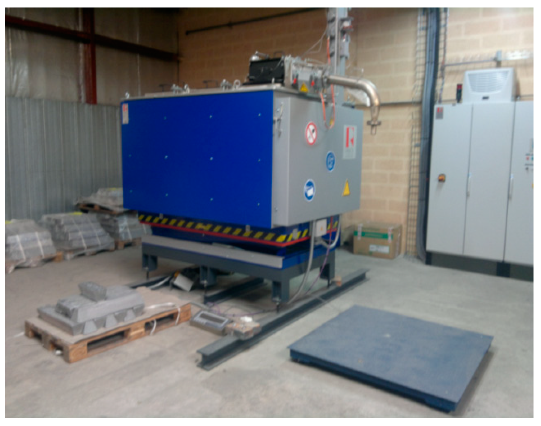
The used CPM was defined to fulfill several critical conditions among which: 1—the greatest possible enthalpy of its solid ↔ liquid transformation (and vice versa); 2—a transition temperature adjusted exactly to the temperature of the Mg ↔ H reactions for a given range of pressure; 3—long-term stability and easy to prepare, cast, and install. Among several solutions, an Mg-Zn-M alloy was selected to melt at ~340 °C with a maximum enthalpy of transformation of ~140 J/g. In practice, an industrial scale foundry was used. As shown in Figure 8, it was equipped with a flow distributor and a connected weight platform to flow the desired amount of CPM. More details on the working temperatures and pressures of operation are given Refs. [23,24,26].
5. Discussing Performances of Solid-State Hydrogen Storage Solutions
The most effective solid-state hydrogen storage systems in terms of energy efficiency obviously depend on various parameters as expressed in the following types of characteristics:
a1—the nature of hydrogen carriers—here considered being metallic-type absorbers,
b1—the type of microstructure developed to operate sufficiently fast kinetic reactions and cycle life,
c1—the design of hydrogen absorbing bodies and their ancillary equipment,
d1—tank design for top functionality according to different target applications,
e1—the energy efficiency of all chemical, physical, and mechanical processes and tools used in the stages considered above.
Due to the latest and most urgent demand for new and decarbonized energy carriers, one can feel an increase in articles, proposals in the field of storage technologies that appear as a choke point between sources and uses energy, both with somewhat intermittent characters.
Densified hydrogen quickly appeared as one of the energy carriers of storable solutions which remains primarily considered for its traditional molecular forms (compressed, cryogenic, LOHC up to adsorbents). Despite intense fundamental and applied research efforts developed on metal hydrides, storage and supply logistics solutions may appear interesting using metal hydride vectors.
Answers to the above main questioned parameters are developed as follows:
a2—In terms of small and medium size, e.g., in domestic applications, metal hydrides at low temperature prove to be very attractive because of their relative ease of use with limited heat transfer constraints close to ambient temperature conditions. Interestingly, certain series exhibit relatively good performances (Ti-V-Cr, e.g., in Refs. [41,42], Mg2Ni e.g., in Refs. [43,44], AB2, e.g., in Ref. [45] high entropy alloys, e.g., in Refs. [46,47] and from overall review [48]). However, their practical absorption level Hmax. remains limited to ~2 w%. In addition, the metals and alloys are made of rather expensive and heavy elements such as Ti, V, Cr, Ni, Zr, Nb, etc. Again, their ultimate decrepitation and pyrophoric characteristics must be carefully evaluated for long-term applications. In contrast, a Hmax practical absorption up nearly to 6.5–7 w% H has been credited to Mg-rich hydrides [49,50] depending on the doping rate with effective additives of said catalysts.
b2—The main drawback of hydride-forming Mg-based materials is the kinetics of the A/D reactions, which has been overcome for more than two decades of experience using high-performance mechanical treatments such as HEBM with specific additives for fine MgH2 powders. At present, rapid progress is realized in mechanical operations using specific SPD techniques specifically developed for bulk Mg-rich alloys [51,52]. However, with both mechanical treatments, the procedures consist of establishing nanometric-sized crystallites within µm-sized particles with high densities of defects (dislocations, vacancies, voids, additive interfaces, etc.). It should be noted that among the wide varieties of additives tested, the most effective are compounds based on d-elements (columns VA to VIII of the Elements Table) (oxides, halides, alloys) to promote activation and nucleation at interfaces [48].
c2—A second apparent disadvantage of the thermodynamic characteristics of MgH2 is that its entropy of formation is about 50 to 80% higher than most transition metal hydrides, called low temperature hydrides. Moreover, the transition temperature TMg↔MgH2 is larger than 300 °C under a few tens of MPa H2 pressure. Additionally, MgH2 presents poor thermal conductivity of ceramic type as mentioned in Section 3.4. In contrast, by doping the activated MgH2 compacts with NEG fibers provides a clear advantage over metal hydrides at low temperatures. This not only concerns the thermal conductivity, but also because low temperature and lower heat of formation make thermal energy regeneration operations nearly ineffective for the low temperature metal hydrides. Then, the compact bodies formed by the MgH2-NEG composite—as shown in Figure 7-Right—are not subject to decrepitation effects, furthermore being mechanically reinforced and endowed with a fairly good thermal conductivity.
d2—The size and dimensions of the elementary compacted disc as shown in Figure 7-Left are perfectly suited to form stacks of storage elements, i.e., separated by conductive metal fins as discussed in Ref. [53]. This makes the H-storage very dense, with no dead volume as needed to accommodate the volume expansion of the low temperature transition metal hydrides during hydrogenation. Thus, short to long cylinder units and multiple multi-cylinder containers can be easily adapted for small to large H storage demands. As mentioned in references [54,55], different geometries are proposed to improve the absorption/desorption heat transfers. However, for large storage units, the simplest design is the best provided that it tracks demand over time. The simplest possible design of the tank makes an effective minimization of the lengths of welding of the tubes and the walls, for more safety against H-permeation. Such considerations facilitate the final recycling of all the materials, finally for global lower costs.
e2—As shown in Figure 1, Figure 2, Figure 4 and Figure 8, unique tools have been developed to safely and efficiently process the materials from the raw magnesium to the final composite solid bodies as that shown in Figure 7-Left. Such a MgH2-rich compact makes loading the equivalent of 650 L of H2 gas in a disc of 1 L in volume and for a weight of ~1 kg possible. The stability of MgH2 at room temperature (because it very low dissociation pressure) makes most of step part of the successive processes rather safe with limited risks of pyrophoricity, except at the HEBM stage. Moreover, because this operation that forms ultra-fine powders is man-power-intensive, energy-intensive, and time-consuming, the easy metal hydride nucleation conditions should be advantageously realized using severe plastic deformation techniques as proposed in Refs. [51,52].
At present, we had developed different types of hydrogen storage units as mentioned in Refs. [20,53]. The equivalent stored energy ranges from 15 kWh in adiabatic mode with CPM units up to a 3.3 MWh unit without any auxiliary heat storage. Interestingly, the first type of HSSS can work 12/12 h, for charging and discharging repeatedly. If more time separates the two A/D operations, the radiation heat losses from the peripheral surfaces can be compensated by a series of low power electric heaters to maintain the exact level of sensible heat.
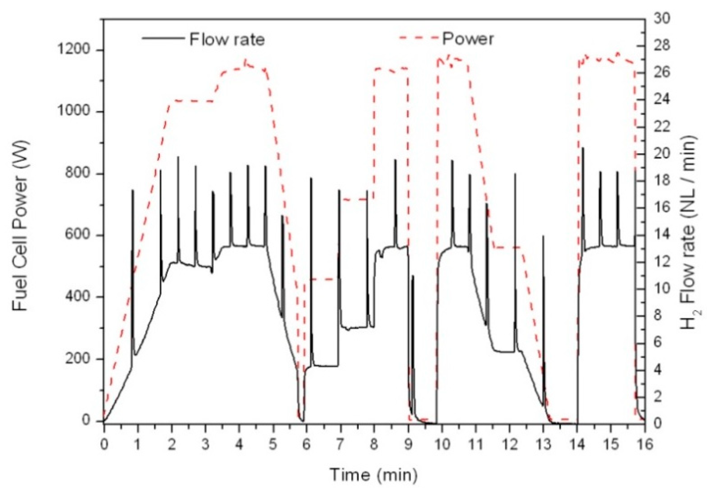
Another interesting mode of operation was tested thanks the autonomous nature of the dual hydrogen/heat storage tank. For example, a fuel cell (PEMFC) can be directly connected to the adiabatic tank without any mass flow or monitored hydrogen flow regulation. Any electrical power demand from the FC control panel is immediately met by an increase of the H2 flow rate automatically delivered from the tank. Since the instantaneous demand (desorption) of hydrogen is endothermic, then the temperature gradient developed at the level of the external wall in contact with the PCM is immediately compensated by the transfer of equivalent heat from the CPM bath. Figure 9 shows that the electrical profile of the FC mimics the corresponding hydrogen flow profile delivered from the MgH2 stack fairly well. The hydrogen storage unit response is within a few seconds, thanks to the NEG concentration (best thermal conductivity) and the additive doping (best A/D kinetics).
6. Target Applications
The main target applications for such solid-state hydrogen storage units are:
6.1. External Heat Transfer Type of Tank
By using the external heat transfer type of tanks to undertake large masses of hydrogen and long-distance transport. This can be realized using on-board container ships as for the existing commercial tankers. The immediate advantages are the absolute safety and the total mass of transported hydrogen which could be up to two to three times larger than those that are possible using the pressurized molecular H2 modes.
In addition, the recoveries of the heat of reaction at adsorption (loading the tanks) can be advantageously managed as mentioned in Section 4.1. Again, desorption (de-loading) could be interestingly done using incoming heat losses.
6.2. Adiabatic Type of Tank
Thanks to the adiabatic types of medium to very large size tanks, hydrogen can be safely available in off-road units. It involves a chain of operations with:
a—production of, e.g., green hydrogen from electrolysis in either continuous or semi-continuous modes (intermittent production),
b—hydrogen distribution via both solid-state storage units and heat storage in safe and dense mode,
c—continuous delivery on demand, either for industries (steel, cement, chemicals, etc.) or for large size refueling stations.
As sketched in Figure 10, heavy mobility (trucks, trains, boats) with daily circuits could be supplied with the first type of dual tanks (containing PCM). As shown in Figure 11, on-site applications will be easily served by the second type of tanks with external heat exchange. A potential heat recovery can be developed from exothermal absorption and similarly the use of lost heat (e.g., from industry processes) can be addressed for the endothermal desorption. It is worth noting that most of the above-mentioned mass applications do not request high hydrogen gas pressure (outing typically at 0.2 to 0.5 MPa).
However, if higher hydrogen pressure is requested, e.g., 35 MPa for refueling station, the use of a metal-hydride (or said thermal) compressor [54,55] would be preferred to a mechanical one in terms of energy efficiency and OPEX (operational expenditure). Effectively, this mode of compression uses low temperature, for example, waste heats (≤90 °C) that can be easily generated besides by the working tanks.
7. Conclusions
Solid-state hydrogen storage (HSSS) in MgH2-based tanks brings several attractive advantages such as safety, compactness, long-term cycles, and lower energy requirements for compaction and shipping. However, the base material must be prepared under well-controlled conditions and the storage units must be designed for the best energy efficiency cycle. Long experiences have been gained from basic research at Institut Néel (CNRS), Grenoble, France [28]. Then, experienced technical developments are now being scaled up at JOMI-LEMAN SA. The privileged on-site development of large storage units will offer a secure and efficient alternative to costly methods (energy, logistics, labor, network, investments, etc.) met to provide H2 when distributed as either compressed or cryogenics molecules.
Author Contributions
Conceptualization: D.F., M.J., N.S., P.d.R., Methodology: D.F., M.J., N.S., P.d.R., Validation: D.F., M.J., N.S., P.d.R., Formal analysis: D.F., P.d.R. All authors have read and agreed to the published version of the manuscript.
Funding
This research received no external funding.
Data Availability Statement
No data available.
Conflicts of Interest
The authors declare no conflict of interest.
References
- Vigeholm, B.; Kjøller, J.; Larsen, B.; Pedersen, A. Formation and decomposition of magnesium hydride. J. Less Common Met. 1983, 89, 135–144. [Google Scholar] [CrossRef]
- Ivanov, E.; Konstanchuk, I.; Stepanov, A.; Boldyrev, V. Magnesium mechanical alloys for hydrogen storage. J. Less Common Met. 1987, 131, 25–29. [Google Scholar] [CrossRef]
- Chen, Y.; Williams, J. Formation of metal hydrides by mechanical alloying. J. Alloys Compd. 1995, 217, 181–184. [Google Scholar] [CrossRef]
- Schulz, R.; Boily, S.; Zaluski, L.; Zaluska, A.; Tessier, P.; Ström-Olsen, J. Nanocrystalline materials for hydrogen storage. Innov. Met. Mater. 1995, 529–535. [Google Scholar]
- Zaluski, L.; Zaluska, A.; Ström-Olsen, J. Nanocrystalline metal hydrides. J. Alloys Compd. 1997, 253, 70–79. [Google Scholar] [CrossRef]
- Dunlap, R.A.; Cheng, Z.H.; MacKay, G.R.; O’Brien, J.W.; Small, D.A. Preparation of nanocrystalline metal hydrides by ball milling. Hyperfine Interact. 2000, 130, 109–126. [Google Scholar] [CrossRef]
- Yamashita, A.; Horita, Z.; Langdon, T.G. Improving the mechanical properties of magnesium and a magnesium alloy through severe plastic deformation. Mater. Sci. Eng. A 2001, 300, 142–147. [Google Scholar] [CrossRef]
- Leiva, D.; Fruchart, D.; Bacia, M.; Girard, G.; Skryabina, N.; Villela, A.C.S.; Miraglia, S.; Santos, D.; Botta, W. Mg alloy for hydrogen storage processed by SPD. Int. J. Mater. Res. 2009, 100, 1739–1746. [Google Scholar] [CrossRef]
- Leiva, D.R.; Jorge, A.M.; Ishikawa, T.T.; Huot, J.; Fruchart, D.; Miraglia, S.; Kiminami, C.S.; Botta, W.J. Nanoscale Grain Refinement and H-Sorption Properties of MgH2 Processed by High-Pressure Torsion and Other Mechanical Routes. Adv. Eng. Mater. 2010, 112, 786–792. [Google Scholar] [CrossRef]
- Skripnyuk, V.M.; Rabkin, E.; Estrin, Y.; Lapovok, R. The effect of ball milling and equal channel angular pressing on hy-drogen absorption/desorption properties of Mg-4.95wt%Zn-0.7lwt%Zr (ZK60) alloy. Acta Mater. 2004, 52, 405–414. [Google Scholar] [CrossRef]
- Skripnyuk, V.; Rabkin, E.; Estrin, Y.; Lapovok, R. Improving hydrogen storage properties of magnesium based alloys by equal channel angular pressing. Int. J. Hydrogen Energy 2009, 34, 6320–6324. [Google Scholar] [CrossRef]
- Skryabina, N.; Aptukov, V.; Romanov, P.; Fruchart, D.; de Rango, P.; Girard, G.; Grandini, C.; Sandim, H.; Huot, J.; Lang, J.; et al. Microstructure Optimization of Mg-Alloys by the ECAP Process Including Numerical Simulation, SPD Treatments, Characterization, and Hydrogen Sorption Properties. Molecules 2019, 24, 89. [Google Scholar] [CrossRef] [PubMed]
- Mori, R.; Miyamura, H.; Kikuchi, S.; Tanaka, K.; Takeichi, N.; Tanaka, H.; Kuriyama, N.; Ueda, T.T.; Tsukahara, M. Hydro-genation characteristics of Mg based alloy prepared by super lamination technique. Mater. Sci. Forum. 2007, 561–565, 1609–1612. [Google Scholar] [CrossRef]
- Lang, J.; Huot, J. A new approach to the processing of metal hydrides. J. Alloys Compd. 2011, 509, 3. [Google Scholar] [CrossRef]
- Vincent, S.; Lang, J.; Huot, J. Addition of catalysts to magnesium hydride by means of cold rolling. J. Alloys Compd. 2012, 512, 290–295. [Google Scholar] [CrossRef]
- Bobet, J.-L.; Chevalier, B.; Darriet, B. Effect of reactive mechanical grinding on chemical and hydrogen sorption properties of the Mg+10 wt.% Co mixture. J. Alloys Compd. 2002, 330–332, 738–742. [Google Scholar] [CrossRef]
- Rivoirard, S.; de Rango, P.; Fruchart, D.; Charbonnier, J.; Vempaire, D. Catalytic effect of additives on the hydrogen absorption properties of nano-crystalline MgH2(X) composites. J. Alloys Compd. 2003, 356–357, 622–625. [Google Scholar] [CrossRef]
- Zaluska, A.; Zaluski, L. New catalytic complexes for metal hydride systems. J. Alloys Compd. 2005, 404, 706–711. [Google Scholar] [CrossRef]
- Du, A.J.; Smith, S.C.; Yao, X.D.; Sun, C.H.; Li, L.; Lu, G.Q. The role of V2O5 on the dehydrogenation and hydrogenation in magnesium hydride: An ab initio study. Appl. Phys. Lett. 2008, 92, 163106. [Google Scholar] [CrossRef]
- Jehan, M.; Fruchart, D. McPhy-Energy’s proposal for solid state hydrogen storage materials and systems. J. Alloys Compd. 2013, 580, 343–348. [Google Scholar] [CrossRef]
- Askri, F.; Jemni, A.; Nasrallah, S. Study of two-dimensional and dynamic heat and mass transfer in a metal−hydrogen reactor. Int. J. Hydrogen Energy 2003, 28, 537–557. [Google Scholar] [CrossRef]
- Capurso, G.; Agresti, F.; Russo, S.L.; Maddalena, A.; Principi, G.; Cavallari, A.; Guardamagna, C. Performance tests of a small hydrogen reactor based on Mg–Al pellets. J. Alloys Compd. 2011, 509, S646–S649. [Google Scholar] [CrossRef]
- Chaise, A.; de Rango, P.; Marty, P.; Fruchart, D.; Miraglia, S.; Olivès, R.; Garrier, S. Enhancement of hydrogen sorption in magnesium hydride using expanded natural graphite. Int. J. Hydrogen Energy 2009, 34, 8589–8596. [Google Scholar] [CrossRef]
- Garrier, S.; Delhomme, B.; de Rango, P.; Marty, P.; Fruchart, D.; Miraglia, S. A new MgH2 tank concept using a phase-change material to store the heat of reaction. Int. J. Hydrogen Energy 2013, 38, 9766–9771. [Google Scholar] [CrossRef]
- Wang, W.; Zhang, M.; Xu, W.; Tian, B.; Li, R.; Shang, M.; Yao, Z. Numerical Simulation on the Hydrogen Storage Performance of Magnesium Hydrogen Storage Reactors. ACS Omega 2023, 8, 4586–4596. [Google Scholar] [CrossRef]
- Delhomme, B.; de Rango, P.; Marty, P.; Bacia, M.; Zawilski, B.; Raufast, C.; Miraglia, S.; Fruchart, D.D. Large scale magnesium hydride tank coupled with an external heat source. Int. J. Hydrogen Energy 2012, 37, 9103–9111. [Google Scholar] [CrossRef]
- Sheppard, D.A.; Paskevicius, M.; Humphries, T.D.; Felderhoff, M.; Capurso, G.; von Colbe, J.B.; Dornheim, M.; Klassen, T.; Ward, P.A.; Teprovich, J.A.; et al. Metal hydrides for concentrating solar thermal power energy storage. Appl. Phys. A 2016, 122, 1–15. [Google Scholar] [CrossRef]
- de Rango, P.; Marty, P.; Fruchart, D. Hydrogen storage systems based on magnesium hydride: From laboratory tests to fuel cell integration. Appl. Phys. A Mater. Sci. Process. 2016, 122, 1–20. [Google Scholar] [CrossRef]
- Jander, W. Kinetic Model for Solid-State Reactions, Zeitschrift für Anorganische und Allgemeine Chemie. Z. Anorg. Allg. Chem. 1927, 163, 1–30. [Google Scholar] [CrossRef]
- Zhou, C.; Zhang, J.; Bowman, R.C.; Fang, Z.Z. Roles of Ti-Based Catalysts on Magnesium Hydride and Its Hydrogen Storage Properties. Inorganics 2021, 9, 36. [Google Scholar] [CrossRef]
- Avrami, M. Kinetics of Phase Change. J. Chem. Phys. 1939, 7, 1103–1112. [Google Scholar] [CrossRef]
- Erofeyev, B.V. Generalized equation of chemical kinet-ics and its application in reactions involving solids. C. R. (Dokl.) Acad. Sci. URSS 1946, 52, 511–514. [Google Scholar]
- Yartys, V.; Lototskyy, M.; Akiba, E.; Albert, R.; Antonov, V.; Ares, J.; Baricco, M.; Bourgeois, N.; Buckley, C.; von Colbe, J.B.; et al. Magnesium based materials for hydrogen based energy storage: Past, present and future. Int. J. Hydrogen Energy 2019, 44, 7809–7859. [Google Scholar] [CrossRef]
- Huot, J.; Amira, S.; Lang, J.; Skryabina, N.; Fruchart, D. Improvement of hydrogen storage properties of magnesium alloys by cold rolling and forging. IOP Conf. Ser. Mater. Sci. Eng. 2014, 63, 012114. [Google Scholar] [CrossRef]
- Aptukov, V.N.; Tsirulnik, I.I.; E Skryabina, N.; Fruchart, D. Importance of thermal conductivity and stress level during a phase (hydride) transformation in magnesium. PNRPU Mech. Bull. 2021, 3, 12–21. [Google Scholar] [CrossRef]
- de Rango, P.; Fruchart, D.; Aptukov, V.; Skryabina, N. Fast Forging: A new SPD method to synthesize Mg-based alloys for hydrogen storage. Int. J. Hydrogen Energy 2020, 45, 14–24. [Google Scholar] [CrossRef]
- Wen, J.; de Rango, P.; Allain, N.; Laversenne, L.; Grosdidier, T. Improving hydrogen storage performance of Mg-based alloy through microstructure optimization. J. Power Sources 2020, 480, 228823. [Google Scholar] [CrossRef]
- Nachev, S.; de Rango, P.; Skryabina, N.; Skachkov, A.; Aptukov, V.; Fruchart, D.; Marty, P. Mechanical behavior of highly reactive nanostructured MgH2. Int. J. Hydrogen Energy 2015, 40, 17065–17074. [Google Scholar] [CrossRef]
- Nachev, S. Evolution Microstructurale et Comportement Mécanique des Composites à Base de MgH2 au Cours des Cycles D’hydruration. Ph.D. Thesis, University Joseph Fourier, Grenoble, France, 2018; p. 154. Available online: https://tel.archives-ouvertes.fr/tel-01686419 (accessed on 5 October 2015).
- Chaise, A. Etude Expérimentale et Numérique de Réservoirs D’hydrure de Magnesium. Ph.D. Thesis, University Joseph Fourier, Grenoble, France, 2008; p. 205. Available online: https://tel.archives-ouvertes.fr/tel-00351465 (accessed on 11 December 2008).
- Sakaki, K.; Kim, H.; Majzoub, E.H.; Machida, A.; Watanuki, T.; Ikeda, K.; Otomo, T.; Mizuno, M.; Matsumura, D.; Nakamura, Y. Displacement of hydrogen position in di-hydride of V-Ti-Cr solid solution alloys. Acta Mater. 2022, 234, 118055. [Google Scholar] [CrossRef]
- Abdul, J.M.; Chown, L.H.; Odusote, J.K.; Nei, J.; Young, K.-H.; Olayinka, W.T. Hydrogen Storage Characteristics and Corrosion Behavior of Ti24V40Cr34Fe2 Alloy. Batteries 2017, 3, 19. [Google Scholar] [CrossRef]
- Ma, Z.; Zhao, Y.; Wu, Z.; Tang, Q.; Ni, J.; Zhu, Y.; Zhang, J.; Liu, Y.; Zhang, Y.; Li, H.-W.; et al. Air-stable magnesium nickel hydride with autocatalytic and self-protective effect for reversible hydrogen storage. Nano Res. 2022, 15, 2130–2137. [Google Scholar] [CrossRef]
- Leiva, D.R.; Costa, H.C.D.A.; Huot, J.; Pinheiro, T.S.; Junior, A.M.J.; Ishikawa, T.T.; Filho, W.J.B. Magnesium-Nickel alloy for hydrogen storage produced by melt spinning followed by cold rolling. Mater. Res. 2012, 15, 813–817. [Google Scholar] [CrossRef]
- Pickering, L.; Lototskyy, M.; Davids, M.W.; Sita, C.; Linkov, V. Induction melted AB 2 -type metal hydrides for hydrogen storage and compression applications. Mater. Today Proc. 2018, 5, 10470–10478. [Google Scholar] [CrossRef]
- Sahlberg, M.; Karlsson, D.; Zlotea, C.; Jansson, U. Superior hydrogen storage in high entropy alloys. Sci. Rep. 2016, 6, 36770. [Google Scholar] [CrossRef]
- Ek, G.; Nygård, M.M.; Pavan, A.F.; Montero, J.; Henry, P.F.; Sørby, M.H.; Witman, M.; Stavila, V.; Zlotea, C.; Hauback, B.C.; et al. Elucidating the Effects of the Composition on Hydrogen Sorption in TiVZrNbHf-Based High-Entropy Alloys. Inorg. Chem. 2020, 60, 1124–1132. [Google Scholar] [CrossRef]
- Sakintuna, B.; Lamari-Darkrim, F.; Hirscher, M. Metal hydride materials for solid hydrogen storage: A review. Int. J. Hydrog. Energy 2007, 32, 1121–1140. [Google Scholar] [CrossRef]
- Sun, Z.; Lu, X.; Nyahuma, F.M.; Yan, N.; Xiao, J.; Su, S.; Zhang, L. Enhancing Hydrogen Storage Properties of MgH2 by Transition Metals and Carbon Materials: A Brief Review. Front. Chem. 2020, 8, 552. [Google Scholar] [CrossRef]
- Dai, M.; Lei, G.; Zhang, Z.; Li, Z.; Cao, H.; Chen, P. Room Temperature Hydrogen Absorption of V2O5 Catalyzed MgH2/Mg※. Acta Chim. Sin. 2022, 80, 303. [Google Scholar] [CrossRef]
- Edalati, K.; Akiba, E.; Botta, W.J.; Estrin, Y.; Floriano, R.; Fruchart, D.; Grosdidier, T.; Horita, Z.; Huot, J.; Li, H.-W.; et al. Impact of severe plastic deformation on kinetics and thermodynamics of hydrogen storage in magnesium and its alloys. J. Mater. Sci. Technol. 2023, 146, 221–239. [Google Scholar] [CrossRef]
- Edalati, K.; Bachmaier, A.; Beloshenko, V.A.; Beygelzimer, Y.; Blank, V.D.; Botta, W.J.; Bryła, K.; Čížek, J.; Divinski, S.; Enikeev, N.A.; et al. Nanomaterials by severe plastic deformation: Review of historical developments and recent advances. Mater. Res. Lett. 2022, 10, 163–256. [Google Scholar] [CrossRef]
- de Rango, P.; Fruchart, D.; Marty, P. Stockage Massif de L’hydrogène Dans L’hydrure de Magnésium. Techniques de l’Ingénieur. 2013, p. 18. Available online: https://www.techniques-ingenieur.fr/base-documentaire/innovation-th10/innovations-en-energie-et-environnement-42503210/stockage-massif-de-l-hydrogene-dans-l-hydrure-de-magnesium-in170/ (accessed on 10 November 2013). [CrossRef]
- Odysseos, M.; de Rango, P.; Christodoulou, C.N.; Hlil, E.K.; Steriotis, T.; Karagiorgis, G.; Charalambopoulou, G.; Papapanagiotou, T.; Ampoumogli, A.; Psycharis, V.; et al. The effect of compositional changes on the structural and hydrogen storage properties of (La-Ce)Ni5 type intermetallics towards compounds suitable for metal hydride hydrogen compression. J. Alloys Compd. 2013, 580, S268–S270. [Google Scholar] [CrossRef]
- Koultoukis, E.D.; I Gkanas, E.; Makridis, S.S.; Christodoulou, C.N.; Fruchart, D.; Stubos, A.K. High-temperature activated AB2nanopowders for metal hydride hydrogen compression. Int. J. Energy Res. Spec. Issue Nano Energy Technol. 2014, 38, 477–486. [Google Scholar] [CrossRef]
Figure 1.
Rotating furnace on left where the sample container is installed as seen on right.

Figure 2.
Left: Ball-millers, with aside a transfer container; Right: Details of a transfer container.
Figure 2.
Left: Ball-millers, with aside a transfer container; Right: Details of a transfer container.

Figure 3.
(a)—As received MgH2 SEM picture, the mean grain size is about 40 μm; (b)—SEM picture after 10 h ball-milling, the mean particle size ranges from 0.2 to 10 μm; (c)—HREM picture of a 6 h ball-milled MgH2, defects and nano-crystalline state transform to well-shaped homogeneous size crystals after hydrogen release under the electron beam; mean grain size ~20 nm; (d)—Electron diffraction picture of insitu well recrystallized Mg from the MgH2 precursor.

Figure 4.
Left—HF induction equipment to prepare metal-type additives, Right—the casting molder.

Figure 5.
Traces recorded at various temperatures of activated MgH2 powders by HEBM, Left: absorption made under 1 MPa H2 pressure, Right: desorption made under 15 kPa H2 pressure.
Figure 5.
Traces recorded at various temperatures of activated MgH2 powders by HEBM, Left: absorption made under 1 MPa H2 pressure, Right: desorption made under 15 kPa H2 pressure.

Figure 6.
XRD texture analysis of an FF sample, Left: radial surface, Middle: along axis surface, and Right: absorption (2 MPa)/desorption (150 kPa) traces made after two activation cycles.
Figure 6.
XRD texture analysis of an FF sample, Left: radial surface, Middle: along axis surface, and Right: absorption (2 MPa)/desorption (150 kPa) traces made after two activation cycles.

Figure 7.
Left—compacted disc of MgH2 composite (ϕ = 30 cm, e ~1 cm) storing 650 Nl hydrogen gas; Right—SEM picture of a section of disc giving evidence that the NGE ribbons are aligned perpendicular to the vertical pressing axis, made to have better radial thermal conductivity.
Figure 7.
Left—compacted disc of MgH2 composite (ϕ = 30 cm, e ~1 cm) storing 650 Nl hydrogen gas; Right—SEM picture of a section of disc giving evidence that the NGE ribbons are aligned perpendicular to the vertical pressing axis, made to have better radial thermal conductivity.

Figure 8.
The CPM smelter (Rauch GmbH, Gmunden, Austria) equipped with a proboscis to pump and flow the melt in the specific volume of the dual tank to be installed on the torque in front of the smelter. This enables distribute the exact amount of CPM necessary to store heat involved at the exo-(endo-) thermal Mg ↔ H2 reactions.

Figure 9.
The trace of hydrogen flow (Nl/min) directly outing from the adiabatic-type tank (black) follows the power (W) demand at the fuel cell control panel (red dashes) exactly and instantaneously. The spikes correspond to the automatic N2 flushes needed on the FC membrane. Note that the tank automatically provides the FC with hydrogen without any mass flow; no more heaters are needed at the tank outing.

Figure 10.
Sketch for long distance, for large mass transportation under very safe conditions using the HSSS heat external-exchange type of MgH2-based tank. Moreover, this solution avoids energy-intensive compressors or liquefiers.
Figure 10.
Sketch for long distance, for large mass transportation under very safe conditions using the HSSS heat external-exchange type of MgH2-based tank. Moreover, this solution avoids energy-intensive compressors or liquefiers.

Figure 11.
On-site production, hydrogen solid-state storage in adiabatic-type MgH2/CPM tanks directly filled from electrolysis and to distribute H2 nearby for rather low pressure uses. Moreover, heat of (for) reaction can be considered for the global energy balance.
Figure 11.
On-site production, hydrogen solid-state storage in adiabatic-type MgH2/CPM tanks directly filled from electrolysis and to distribute H2 nearby for rather low pressure uses. Moreover, heat of (for) reaction can be considered for the global energy balance.

Disclaimer/Publisher’s Note: The statements, opinions and data contained in all publications are solely those of the individual author(s) and contributor(s) and not of MDPI and/or the editor(s). MDPI and/or the editor(s) disclaim responsibility for any injury to people or property resulting from any ideas, methods, instructions or products referred to in the content. |
© 2023 by the authors. Licensee MDPI, Basel, Switzerland. This article is an open access article distributed under the terms and conditions of the Creative Commons Attribution (CC BY) license (https://creativecommons.org/licenses/by/4.0/).
Share and Cite
MDPI and ACS Style
Fruchart, D.; Jehan, M.; Skryabina, N.; de Rango, P. Hydrogen Solid State Storage on MgH2 Compacts for Mass Applications. Metals 2023, 13, 992. https://doi.org/10.3390/met13050992
AMA Style
Fruchart D, Jehan M, Skryabina N, de Rango P. Hydrogen Solid State Storage on MgH2 Compacts for Mass Applications. Metals. 2023; 13(5):992. https://doi.org/10.3390/met13050992
Chicago/Turabian StyleFruchart, Daniel, Michel Jehan, Nataliya Skryabina, and Patricia de Rango. 2023. "Hydrogen Solid State Storage on MgH2 Compacts for Mass Applications" Metals 13, no. 5: 992. https://doi.org/10.3390/met13050992
Note that from the first issue of 2016, this journal uses article numbers instead of page numbers. See further details here.