Review

A Review on Capturing Twin Nucleation in Crystal Plasticity for Hexagonal Metals

1
Center for Advanced Vehicular Systems, Mississippi State University, Mississippi State, MS 39762, USA
2
Department of Mechanical Engineering, Mississippi State University, Mississippi State, MS 39762, USA
3
Mechanical and Mechatronics Engineering, University of Waterloo, 200 University Ave. W, Waterloo, ON N2L3G1, Canada
4
U.S. Army Research Laboratory, Chicago, IL 60615, USA
5
School of Automotive Engineering, Université Internationale de Rabat, Rabat-Shore Rocade Rabat-Salé, Rabat 11103, Morocco
*
Authors to whom correspondence should be addressed.
Metals 2021, 11(9), 1373; https://doi.org/10.3390/met11091373
Submission received: 29 July 2021 / Revised: 23 August 2021 / Accepted: 24 August 2021 / Published: 30 August 2021

Abstract

:
Owing to its ability to incorporate Schmid’s law at each integration point, crystal plasticity has proven a powerful tool to simulate and predict the slip behavior at the grain level and the ensuing heterogeneous stress/strain localization and texture evolution at the macroscopic level. Unfortunately, notwithstanding substantial efforts during the last three decades, this remarkable capability has not been replicated for materials where twinning becomes a noticeable deformation mechanism, namely in the case of low-stacking fault energy cubic, orthorhombic, and hexagonal close-packed structures. The culprit lies in the widely adopted unphysical pseudo-slip approach for capturing twin formation. While the slip is diffuse, twinning is a localized event that occurs as a drastic burst of a confined number of partial twinning dislocations establishing an interface that pursues growth through a thread of perfect twinning dislocations in the sense of bicrystallography. Moreover, at earlier stages, twin nucleation may require atomic diffusion (Shuffling) and faceting, generally demanding higher stress levels not necessarily on the twin shear plane, while triaxiality at adequate sites might be needed or preferred such as lower grain boundary misorientations or other twin boundaries. Identifying a mathematical framework in the constitutive equations for capturing these twin formation sensitivities has been a daunting challenge for crystal plasticity modelers, which has stalled ameliorating the design of key hexagonal materials for futuristic climate change-related industries. This paper reviews existing approaches to incorporating twinning in crystal plasticity models, discusses their capabilities, addresses their limitations, and suggests prospective views to fill gaps. The incorporation of a new physics-based twin nucleation criterion in crystal plasticity models holds groundbreaking potential for substantial progress in the field of computational material science.

1. Introduction

Twinning plays a prominent role in the plastic deformation and recrystallization of low symmetry crystals such as those showing hexagonal close-packed (hcp), orthorhombic, body-centered cubic and even face-centered cubic crystal structures holding a very low stacking fault energy, e.g., twinning induced plasticity steels. In hcp metals such as magnesium (Mg), twinning can be profuse depending on the alloy chemical composition, texture, strain rate, and temperature, while concomitant slip leads to complex interactions with existing twins in the deforming lattice, thereby exacerbating hardening and ultimately damage. Mitigating these interactions in materials design paradigms to ameliorate their properties for many futuristic applications has been a daunting challenge. For instance, wrought Mg alloys have not yet penetrated the automotive market to replace their aluminum and steel counterparts, notwithstanding intense research studies. This incites the need to develop a rigorous understanding of all the factors surrounding the origin of twinning, how it thrives in the lattice, and interacts with slip dislocations and other twins and defects. Crystal plasticity models, whether mean-field or full–field, have proven a good test for the depth of our understanding of the mechanisms driving plastic deformation in polycrystals [1,2,3,4,5,6,7,8,9,10,11,12,13,14]. A comparison of crystal plasticity predictions of the macroscopic and microscopic (case of full–field) behaviors under various conditions of external loading against experimental results, whether testing or digital image correlations, proved to be very helpful in identifying gaps in our understanding and calling for more small–scale modeling and characterization to reveal the associated missing mechanisms. Over the last decades, molecular dynamic (MD) simulations played a crucial role in identifying these mechanisms, which should be captured up in the crystal plasticity models [15,16,17,18,19,20,21,22]. This paper provides a review and a futuristic view of various scholastic works made to enhance crystal plasticity models in their prediction of the mechanical behavior of materials with twins. We emphasize efforts to incorporate twin nucleation in these models, which remains the most challenging event in this entire endeavor.

1.1. Twinning Mechanisms

Twinning in hcp metals is primarily due to the inability of the material to provide “easy” 〈c〉–axis slip deformation with both a low temperature and high strain rate. For instance, in hcp metals, the critical resolved shear stress of glissile pyramidal 〈c + a〉 slip mode is so high at room temperature that it exceeds that of { 1 0 1 ¯ 2 } twinning, which then readily triggers when the external load requires tension/extension or compression/contraction of the 〈c〉–axis for c / a ratio less or larger than 3 , respectively.
A crystallographic description of twinning was originally given by Christian and Mahajan [23]. A twin is formed mainly by four symmetry operations:
  • reflection in K 1 ;
  • rotation of 180 about η 1 ; and
  • reflection in the plane normal to η 1 ; and
  • rotation of 180 about the direction normal to K 1 .
Twinning, or more precisely compound twinning, in general, is the re-orientation of a fraction of the original lattice to the mirror image position due to a simple shear of the lattice. The plane about which this mirroring occurs is the K 1 plane. Figure 1 depicts the four crystallographic twinning elements. K 1 and η 1 are the invariant twin plane and the shear direction, respectively. K 2 is the conjugate twin plane, while P is the plane of shear. The intersection of K 2 and P results in the conjugate direction η 2 . The shear plane P contains η 1 , η 2 , and the normals to K 1 and K 2 . Based on these crystallographic elements, hcp twins can be classified as Type I ( K 1 and η 1 are rational) or Type II ( K 2 and η 2 are rational) even if all are rational sometimes. In hcp metals, a simple shear may not be enough for generating appropriate twinned crystal structures [23], and hence, an additional small atomic displacement, called shuffle [24], in a direction different from the lattice shear may be required. El Kadiri et al. [25] developed the first comprehensive crystallographic theory that provides with a unique sets of equation for the amount of shear and shuffle displacement for all compound twins in hcp lattices.
Based on the formation mechanism, twins can also be classified into 3 groups: (i) growth twins, (ii) transformation twins, and (iii) deformation twins [23]. Growth twins are formed during nucleation and growth processes, such as crystal growth from the vapor or liquid phases, and belong to special kinds of grain boundaries (GBs) [23,26]. Transformation twins are formed during solid state transformation, while deformation twins are formed due to the application of external stress and/or internal stresses, such as residual stresses. This paper focuses on the plasticity due to deformation twinning or, as termed by Christian, glide twinning.
Current twin nucleation models tuned for hcp metals can be divided into homogeneous and heterogeneous nucleation models. The homogeneous model relies on the nucleation of a twin domain through high stress concentration in a pristine parent domain [27], whereas the heterogeneous model accounts for the pre-existing twin defects as a cause for twin nucleation [27,28,29,30,31,32,33]. The experiments by Beyerlein et al. [33], Wang et al. [34] suggest that the latter type of twin nucleation models are superior. This review discusses both types of nucleation models and their applications.

1.1.1. Homogeneous Twinning

The first homogeneous twin nucleation model was introduced by Orowan [35], where he derived an expression for the minimum stable size of a twin nucleus in Zn. Price [36] studied differences between twinning in bulk crystals and in dislocation free whiskers and platelets and construed that homogeneous twinning requires higher stresses than heterogeneous twinning. Christian and Mahajan [23] calculated energy for homogeneous nucleation of twins in Zn and found a value of 75 eV, which was very large. This led to the conclusion that homogeneous twinning is hardly possible unless there is a very high stress and very low surface and strain energies. Lebensohn and Tomé [1] also found in their calculations that very high energies are required for homogeneous twinning. Such energy can not be provided by thermal fluctuations, thereby eliminating the chance of homogeneous twin nucleation. Using MD simulations, Barrett et al. [37] showed that { 1 0 1 ¯ 2 } twinning is impossible to nucleate in pure Mg unless a void is introduced to the simulation box, which lowers the energy barrier for nucleation. In return, in a pristine lattice, { 1 1 2 ¯ 1 } twinning was the only active twin mode, which is obviously not experimentally observed in Mg. The absence of atomic shuffling in { 1 1 2 ¯ 1 } twinning suggests that the energy barrier for homogeneous nucleation is exacerbated by atomic shuffling. In fact, since shuffles correspond to the transport of atoms through diffusion mechanisms, a sufficient level of the gradient of hydrostatic pressure would be required to form a { 1 0 1 ¯ 2 } embryo [38]. A void promotes triaxiality and, as such, the required gradient of hydrostatic pressure.

1.1.2. Heterogeneous Twinning

Bell and Cahn [28] found in their experiments that stresses required for twinning decreased as the specimen was slightly bent or contained an existing twin lamella. In another study, Bell and Cahn [39] mentioned that crystals indented under a stress twin immediately. Price [36] conducted experiments on Zn whiskers and platelets and found that in large crystals, twins are initiated in bursts and grow at fluctuating stresses and high speeds, while in nearly perfect crystals, they grow at almost constant stress and a controllable rate. Lebensohn and Tomé [1] stated that any microstructural feature acting as a stress concentrator or having an associated extra energy improves the chances of inducing twin nucleation. Experiments performed by Lay and Nouet [40] showed that for small twins, few defects are contained in the interfaces, and for large twins, many dislocations are generally found in the twin walls.

1.2. Twin Nucleation

Based on the experiments that showed nucleation of twin is easier with pre-existing defects in Zn crystals, Bell and Cahn [28] hypothesized that there are three stages in twinning: creation, spreading, and thickening of twins and these processes require stresses in decreasing order. Bilby and Entwisle [41] examined the stress fields around two types of inhomogeneities arising during plastic deformation (bounded slip bands and kink bands) and their influence on the formation of mechanical twins. The presence of plastic deformation is required for twin formation. Orowan et al. [35] derived a formula for the minimum stable size of a twin nucleus in zinc crystal by considering energies of dislocation loops and work effected by the applied stress. Bell and Cahn [39] proposed an argument that a twin nucleus must be created as a whole by a locally homogeneous shear of the lattice and not by progressive motion of dislocations. Chyung and Wei [42] studied the effects of stress concentrations on twin nucleation in Zn bicrystals and concluded that strongly locked dislocations, such as the leading dislocation of a pile-up against a barrier, may become a potential twin nucleus. A twin embryo can grow to a stable sized twin nucleus when sufficient stress is applied to it. Figure 2a shows the ∼ 30 nm thick { 1 0 1 ¯ 2 } twin nucleus as observed in Mg AZ31 alloy using transmission electron microscope (TEM) [43]. The new twin nucleus has a lenticular shape with pointed twin tips that can be further observed in the high–resolution TEM images in Figure 2b,e. Efforts were made by Meyers et al. [44] and Fischer et al. [45,46,47,48] to quantify twin morphologies and twin stresses using thermodynamics and other energy-based approaches so that this information can be bridged to higher scale crystal plasticity models.
Hooshmand et al. [49] studied the interactions between 〈a〉, 〈c〉, and 〈c + a〉 dislocations with { 1 ¯ 0 1 1 } and { 1 ¯ 0 1 3 } twin boundaries in Ti using MD simulations and found that these interactions are twin growth mechanisms. They also found that { 1 0 1 ¯ 2 } twin embryo could nucleate from { 1 0 1 ¯ 3 } twin boundaries. Wang et al. [50] studied the nucleation of twins in hcp structures via MD simulations and identified twin nucleation through a mechanism they termed “pure shuffle” and growth via a glide-shuffle mechanism. Ghazisaeidi and Curtin [51] studied { 1 0 1 ¯ 2 } twin nucleation in Mg using atomistic simulations and inferred that dislocation–assisted mechanisms for twinning in Mg are feasible, apart from twin nucleation at grain boundaries. Wang et al. [34] used atomistic simulations to study twin nucleation in Mg and found that twins are most likely to nucleate at grain boundaries—preferably more at low misorientation angle GBs than high angle GBs. Kumar et al. [52] studied { 1 0 1 ¯ 1 } , { 1 0 1 ¯ 2 } , and { 1 0 1 ¯ 3 } coherent twin boundaries (CTB) and coherent basal prismatic (CBP)/coherent prismatic basal (CPB) boundaries in six hexagonal metals using the VASP code [53,54,55]. Several important conclusions were drawn, such as the creation of excess volume during twin formation, the solubility of solute atoms being better at twin boundaries than in the bulk, and the formation energy of { 1 0 1 ¯ 2 } CTB being higher in metals with c / a < 8 / 3 and lower in metals with c / a > 8 / 3 than the formation energies of { 1 0 1 ¯ 1 } and { 1 0 1 ¯ 3 } CTBs. Another conclusion was that { 1 0 1 ¯ 2 } CTB has higher energy than the CBP/CPB boundary for all metals. Wang et al. [17] conducted DFT calculations in Mg to study [ 1 0 1 ¯ 1 ] { 1 0 1 ¯ 2 } twin nucleation in hcp metals. A { 1 0 1 ¯ 2 } twin in an hcp lattice was found to have a minimum thickness of 17 crystallographic { 1 ¯ 0 1 2 } planes in their simulation. A two-layer twin is unstable, and the formation energy of twin boundaries decreases with increasing thickness of { 1 0 1 ¯ 2 } twins. In another study, Wang et al. [18] studied { 1 0 1 ¯ 2 } twinning mechanisms in hcp crystals using topological analysis and atomistic simulations. Normal and zonal twinning mechanisms were studied using DFT and empirical potentials for { 1 0 1 ¯ 2 } twin nucleation. For the normal twinning mechanism, the stable twin nucleus consists of three twinning dislocations corresponding to a thickness of six { 1 0 1 ¯ 2 } planes. For the zonal twinning mechanism, the stable twin nucleus consists of n (n is determined from DFT calculations) twinning dislocations corresponding to ( 2 n + 1 ) crystallographic { 1 ¯ 1 2 1 } planes. Xu et al. [56] performed MD simulations of Mg to study twin nucleation and twin growth and argued that { 1 ¯ 1 ¯ 2 1 } –type twinning is the most preferential mode as their growth is led by the pure shear process. It was observed that increasing the stress can lead to secondary { 1 ¯ 1 ¯ 2 2 } twinning, which migrates by pyramidal slip. All of these mechanisms and properties associated with twinning demonstrate the complexity of understanding and predicting the mechanical behavior of materials implicating twinning.

1.3. Twin Propagation

The formation and propagation of twins are greatly affected by the grain size and the texture in a polycrystalline material [57,58,59,60,61,62]. Antonopoulos et al. [63] conducted TEM observations in Zn specimens to observe the deformation twin modes. It was observed that dislocations with a weaker contrast are visible only along a segment of a twin boundary and responsible for twin growth. The effect of secondary twinning on twin growth was studied by Barnett et al. [64] using EBSD analysis on an Mg AZ31 alloy, who found no evidence supporting an effect. Out of the four { 1 0 1 ¯ 1 } { 1 0 1 ¯ 2 } double twinning variants, the one with the misorientation relation of 37.5 degrees < 1 2 ¯ 1 0 > was found to display high rate of lateral growth, and it is due to the tendency of this twinning variant to minimize the compatibility strain.
Beyerlein and Tomé [10] mentioned that twinning dislocations of the predominant twin system (PTS) are responsible for twin growth as they are often the most active twin dislocations. On the other hand, slip dislocations provide resistance to twin growth and eventually suppress it. Capolungo and Beyerlein [27] developed a 3D model of twinning in hcp materials. The chances of twinning dislocations breaking away and contributing to the formation of twins or twin growth are higher if twins are at a larger equilibrium distance from the reaction center. In other words, a twin can grow by the coalescence of twin nuclei or by the expansion of twin fault loops, or it can also grow by the creation of twinning dislocation dipoles. Capolungo et al. [65] investigated the interactions between slip dislocations and { 1 0 1 ¯ 2 } and { 1 1 2 ¯ 2 } twins. It was observed that a slip dislocation interacting with a { 1 0 1 ¯ 2 } twin boundary helps twin growth if it dissociates into glissile twin dislocations. Twin nucleation and growth can also occur by dislocation pile-ups. TEM observations performed by Wang and Agnew [66] show interactions between dislocation and { 1 0 1 ¯ 2 } twin. The interfacial interactions with an abundant amount of transmuted dislocations along the twin boundary, as shown in Figure 3, results in twin advancement and rapid hardening. Figure 2e shows various features, such as dislocation pileups at twin boundary, transmuted dislocations, and stacking faults observed in Figure 3b–d, respectively. Capolungo et al. [65] also performed experiments in strongly textured pure Zr samples under different loading conditions of temperature and compression. A conclusion was made that pre-existing { 1 0 1 ¯ 2 } twin boundaries and prismatic dislocations do not have a significant effect on { 1 0 1 ¯ 2 } twin growth, but these twin boundaries and dislocations can hinder the propagation of { 1 1 2 ¯ 2 } twins. Meanwhile, using the climbing image nudged elastic band method, Tang et al. [67] showed the diffusive nature of the extension twin boundary and its athermal characteristics above critical stress. The faceted boundary plays a significant role in twin embryo nucleation and twin boundary mobility [16]. The twin may grow on boundaries other than the twin plane boundary and overcome obstacles or lower interface energy by means of faceting. Transmission electron microscope (TEM) experiments performed by Zhang et al. [43], as shown in Figure 2, show the microstructural features of a new twin nucleus with four representative areas shown by red boxes and the high–resolution TEM images in Figure 2b–e, respectively. The image in Figure 2d confirms the { 1 0 1 ¯ 2 } twin orientation relationship with the matrix. The lenticular-shaped twin has a twin boundary that consists of straight terraces and step-like structures from CPB/CBP boundaries.
Upon the application of stress, the atoms move in an organized way to create defects such as dislocations, disclination dipoles, twinning, faceting, etc. At the continuum scale, these defects make it complex to formulate models that can capture or extrapolate those small–scale phenomena. Twinning mechanisms, such as nucleation, propagation, and growth, play a significant role in determining the final microstructure of the material. Site-specific embryonic twin nucleation in a homogeneous stress state is not yet deterministic, although Barnett et al. [60], Paudel et al. [68], Siska et al. [69] have done some work to estimate the nucleation of the next twin based on the stress state of the first one. Giri et al. [70,71] tried to predict twin formation susceptibility based on energy criteria using the nudged elastic band (NEB) method. A discrete dislocation-based modeling of a twin is performed by Lloyd [72] to study the stress state of a twin and predict the twin transfer at grain boundaries. The continuum-based crystal plasticity method does not directly comprehend the discrete information obtained from MD, and hence, it is necessary to bridge these two scales for an appropriate flow of information to better understand the material behavior. The next section discusses the CP methods and the evolution of CP models to incorporate the above-mentioned features of twinning in CP models.

2. Crystal Plasticity Modeling

2.1. Early Rate-Independent Crystal Plasticity Models

Numerical methods based on crystal plasticity theories have taken a pragmatic approach to understanding the macroscopic and microscopic behavior of different material systems. The early crystal plasticity theory can be traced back to Taylor and Elam [73,74] and Taylor [75,76], where a quantitative description of plastic flow due to crystallographic slip is developed. From the standpoint of modern continuum mechanics, Mandel [77] and Hill [78] formulated constitutive equations for elastoplastic behavior in single ductile crystals. These crystal plasticity theories were extended to finite deformations by Rice [79] and Hill and Rice [80]. Van Houtte [5] performed, for the first time, a rate-independent simulation to predict deformation textures considering the role of mechanical twinning along with crystallographic slips. All of these models use a rate-independent method for crystal plastic deformation, which has three main issues [81]:
1.
determining the slip systems that are active;
2.
determining the increments of shear on the active slip systems; and
3.
selecting slip systems required to produce an arbitrary deformation increment, which is not necessarily unique.
Peirce et al. [82] implemented the first two-dimensional numerical scheme for rate-independent elastic–plastic single crystals with non-homogenous deformation. This strategy lacked the determination of active slip systems and the amount of slip on these systems, leading towards the path of rate-dependent schemes.

2.2. Rate-Dependent Crystal Plasticity Models

Peirce et al. [83] developed a rate–sensitive CP model able to predict unique constitutive responses for arbitrary deformation histories. Asaro and Needleman [84] extended the rate-dependent crystal plasticity model to predict deformation textures and large-strain hardening behavior with varying stress–strain histories. For plastic deformation that occurs by crystallographic slip, a comprehensive constitutive relation was established by Asaro and Needleman [84] to model the evolution of crystallographic textures and the anisotropic stress–strain responses. These constitutive models used a semi–implicit time integration scheme developed by Peirce et al. [82,83]. Kalidindi et al. [85] developed a fully implicit time-integration procedure that rigorously predicted the stress–strain behavior and the texture evolution for both homogenous and non-homogenous deformation conditions.

2.3. Incorporation of Twinning

All of these crystal plasticity models are confined to single–phase, high stacking fault energy (SFE), cubic metals, in which plastic deformation occurs predominantly by slip. As mentioned in Section 1, for a number of other cubic metals and non-cubic metals, the deformation is dominated by deformation twinning that changes the stress–strain response [23,86,87,88] as well as the texture evolution [89,90,91]. Van Houtte [5], Chin et al. [92], and Tomé et al. [6] faced challenges of successfully incorporating deformation twinning in a crystal plasticity model. The major challenge was the proliferation of orientations created by the twinned regions, which are different from the untwinned regions of the grain. For instance, if each grain produces one twin at each time step, it will produce 2 n grain orientations after n time-steps. Van Houtte [5] resolved the problem by tracking the volume fraction of activated twins for each grain and selecting single orientations at random, where the probability of a given parent grain and twin variant is scaled by the current volume fraction. At the end of each time step, the number of grains remained the same. Tomé et al. [6] showed that this scheme has two main disadvantages: (i) the statistical criterion used in the scheme requires a large number of grain orientations and (ii) the reorientation decision at every time step does not consider the deformation history. To resolve this problem, Tomé et al. [6] proposed two different approaches to track the twin orientation at different time steps. The first approach is “the volume fraction transfer (VFT)” scheme. The VFT approach specifies a discretized space to represent an orientation space and tracks the weighted volume to represent the texture of the polycrystal. The volume fraction transfer between these discrete regions, which is proportional to shear accommodation, determines the crystal reorientation during deformation. The second approach is the predominant twin reorientation (PTR) scheme. Like Van Houtte’s scheme for tracking different orientations, the PTR scheme chooses the crystallographic orientation of either twinned region or untwinned region. However, the PTR scheme compares the accumulated volume fraction represented by the twin-reoriented grains with accumulated twinned fraction associated with the twinning shear as a criterion for making the reorientation choice.

2.4. Kalidindi’s Lagrangian Method of Incorporating Twin

Kalidindi [7] introduced a new constitutive framework incorporating deformation twinning in a polycrystal plasticity model together with an efficient time-integration scheme [85]. Unlike approaches by Van Houtte [5] and Tomé et al. [6], the calculation occurs in the relaxed configuration (see Figure 2) in which the lattice orientation of the twinned and the untwinned regions are pre-defined based on the initial lattice orientation of the crystal. This constitutive framework is the most comprehensive and amendable technique in the crystal plasticity finite element method (CPFEM). Therefore, this technique is widely used as a framework to construct new CPFEM models.
Staroselsky and Anand [93] proposed constitutive models to compute both texture and twin volume fraction, where a model based on the total Lagrangian approach to predict twin volume fraction and texture evolution was advanced by Kalidindi et al. [85], Kalidindi [94].
Wu et al. [95] presented a Taylor–type crystal plasticity model to predict the evolution of crystallographic texture and an anisotropic stress-strain curve during large plastic strains in Titanium. Clausen et al. [96] simulated the Van Houtte [5] scheme with grain proliferation since the technological advancement allowed to track all grains. In the study, Clausen et al. [96] maintained the relationship between parent and twin material although the original, precise twin crystallographic relationship between the two may no longer be strictly enforced. The stress field in a matrix–twin composite after the formation of a deformation twin has been analyzed by Knezevic et al. [97] using Kalidindi’s CPFE framework to study the conditions affecting the mobility of the twin-matrix interface. Lévesque et al. [9] developed a new framework incorporated with in-house codes by Inal et al. [98] to simulate large deformation behavior in hcp metals that considered the crystallographic slip and deformation twinning as principal deformation mechanisms. In the study, the crystallographic framework considered the dislocations inside the twinned region, which will be discussed in Section 3. Izadbakhsh et al. [99] proposed a new crystal plasticity constitutive model that incorporated plastic deformation due to primary extension twins, primary contraction twins, secondary (double) twins, as well as basal and non-basal slip system in all parent grain, primary twins, secondary twins, and double twins.
Kalidindi’s CPFE approach [7,85] was used by Abdolvand and Daymond [100] to investigate the internal strain and texture development based on various assumptions of twin–parent interactions. Abdolvand and Daymond [101], Abdolvand et al. [102] used the same model to simulate the effect of grain boundary geometry and texture on twin inception and propagation, as well as the 3D stress development in parent and twin pairs in Zircaloy-2. In addition, FEM with polycrystal constitutive description in each integration point is employed by [103,104,105,106] to investigate the deformation behavior of hcp metals. Wu et al. [12] developed a new twin nucleation, propagation, and growth (TNPG) model motivated by the studies of [107,108] on deformation mechanisms in amorphous glassy polymers. Similarly, Cheng and Ghosh [109] developed a physics-based crystal plasticity FE model of dislocation-mediated heterogeneous deformation and tensile twin nucleation in single-crystal Mg and the polycrystalline alloy Mg AZ31. They expanded their FE model with a new propagation approach based on the glide velocity of twin partial dislocation through shear and shuffling mechanisms [110].
Ardeljan et al. [111,112,113] used a 3D CPFE framework incorporated with a deformation twin through a novel approach, where twin lamella is automatically inserted across its parent grain when the twin volume fraction reaches the threshold value. The propagation process was implemented by Qiao et al. [114], who used the CPFE framework with Wu et al. [12]’s TNPG model and Tomé et al. [6]’s PTR scheme. Qiao et al. [114] noticed that stress relaxation from twin nucleation in the TNPG model played an important role for twin propagation across a grain boundary. Lévesque et al. [115] extended the framework developed in [9,98] to consider separate rigid body rotation of the twinned region and parent matrix. A stress relaxation associated with twin propagation accounted in the TNPG method was incorporated with the TDT model of Wang et al. [11,116] in a CPFE framework by Qiao et al. [114]. Figure 4 shows the evolution of the twinned area fraction during fatigue deformation behavior of a 2% precompressed Mg AZ31 sample observed by Hong et al. [117]. The microstructural changes during the 5/4 fatigue cycle show that the twinning in precompressed Mg AZ31 specimen accommodates deformation by the detwinning process. Reversed loading to compression causes twinning again, making an addition to the preexisting twins. The detwinning starts to operate from the first compressive unloading and runs through the second tensile loading with a final twinned area fraction of 9.7% reduced from initial 22% at the precompressed condition, as seen in Figure 4.
Several researchers Proust et al. [118], Knezevic et al. [119] have used the composite grain (CG) approach to determine the deformation twin in their crystal plasticity models. All these CPFE models for crystal plasticity of twinning are based on the framework developed by Kalidindi (1998), where twinning is considered as a pseudo-slip mechanism.

2.5. Fast–Fourier Transfer (CPFFT) Based Method

Finite element methods (FEM) possess limitations related to meshing (requiring fine meshes) and difficulties related to a large number of degrees of freedom, limiting the complexity and size of the microstructures that can be investigated. Similarly, the prediction of intracrystalline states using homogenization techniques requires n–site self–consistent approaches [120,121] instead of classical one-site formulation [122,123] in which ideal crystals are considered to deform embedded in a homogeneous medium with average properties [3]. These limitations of both the small–scale FEM and n-site self–consistent models can be overcome with a novel approach. As an alternative to the CPFE approach, a full–field approach using the crystal plasticity fast-Fourier transform (CPFFT) method was developed by Lebensohn [3], Lebensohn et al. [124], Prakash et al. [125] motivated by the work of Moulinec and Suquet [126], Michel et al. [127] on composite materials. Initially, a self–consistent elasto-viscoplastic model was developed by Hutchinson [128], Molinari et al. [129] and evolved to account for large anisotropic viscoplastic deformation by Lebensohn and Tomé [130], Lebensohn et al. [131]. Based on the FFT algorithm, Moulinec and Suquet [126,132] developed an iterative method to compute the effective properties and local response of elastic and elastoplastic composites. This method works with better numerical performance than CPFE for periodic heterogeneous microstructures to provide an exact solution of the governing equations. However, the convergence of this method is limited to few initial iterations for low rate sensitivity and strongly anisotropic materials [133]. This limitation was overcome by an application of an augmented Lagrangian method [127] on the FFT formulation for isotropic composites with a high contrast of properties. Since the CPFFT method is limited to periodic boundary conditions, CPFE models are suitable for more complex boundary conditions.
In 2008, Lebensohn et al. [124] used visco-plastic fast Fourier transform (VPFFT) to model the subgrain texture evolution in polycrystalline copper. Stress gradients and orientation gradients were captured using VPFFT, showing stress localizations near grain boundaries [134]. Extensions of the viscoplastic self–consistent (VPSC) model have been proposed by Proust et al. [4] and Knezevic et al. [119]. Lebensohn and Needleman [135] implemented a non-local polycrystal plasticity theory using FFT on three-dimensional FCC polycrystals to analyze the mechanical response of polycrystalline aggregates accounting for size dependency that arose from plastic strain gradient. In recent years, Barnett et al. [60], Siska et al. [69], and Paudel et al. [68] showed that the stress relaxation due to twin formation is significant during modeling of twin formation and growth in a crystal plasticity model. The effects of different microstructural aspects such as misorientation, low angle boundaries, autocatalysis, and twin aspect ratios during the growth and propagation of deformation twins are studied by Kumar et al. [69,136,137,138,139,140] using the crystal plasticity fast Fourier transform (CPFFT) method.

2.6. Coupled Crystal Plasticity and Phase-Field Model (CP-PFM)

In recent years, crystal plasticity models have been coupled with phase-field (PF) methods to study the twinning mechanisms [141,142,143,144,145], where twinning is modeled as a phase transformation, and plastic deformation is computed using crystal plasticity methods. Phase-field models, first started by Khachaturian [146], have been successful to predict austenite-martensite transformation in steels [147] and tetragonal–monoclinic transformation in zirconia [148]. In hcp Mg, Pi et al. [149] used the phase-field model to study the tensile twins using twin interfacial energy as a driving force. Later, the coupled CP-PF models are successfully used to study deformation behavior associated with slip induced plasticity, and twinning and detwinning [141], twin nucleation and thickening [142,143], twin morphologies [144], and twin interactions with other slip systems, twins, and grain boundaries [142,145].
All of these models have evolved with time to incorporate various deformation mechanisms observed at mesoscale and microscale levels. The main challenge for recent material scientists is to model physics-based twin nucleation criteria to incorporate into CPFEM or CPFFT models. In the following sections, different CP approaches as well as the current techniques developed to incorporate twins in these CP models are discussed.

3. Crystal Plasticity Finite Element Method (CPFEM)

The mathematical formulation for the crystal plasticity finite element method is based on the theory of continuum mechanics and the decomposition property of a deformation gradient. In this section, crystal plasticity formulation by Lévesque et al. [115] is summarized that uses an updated Lagrangian approach to incorporate the twinning mechanism. Throughout the formulation, bold letters and symbols are used for tensors and vectors unless defined otherwise in the text. Similarly, ( ) · ( ) represents dot product, and ( ) ( ) represents tensor product.

3.1. Total Deformation

The deformation gradient, F, can be decomposed into the elastic and the plastic part (see Figure 5).
F = F * · F P ,
where F* is the elastic deformation. Rigid body rotation and crystallographic slip and twinning are included in F P . The velocity gradient can be written as:
L = F ˙ · F 1 = L * + L P
where L * = F ˙ * · F * 1 , L P = F * ( F ˙ P · F P 1 ) F * 1 . The velocity gradient has the symmetric stretching part, D, and asymmetric part spin tensor, Ω , which can be decomposed into elastic and plastic parts.
L = D + Ω , D = D * + D P , and Ω = Ω * + Ω P
where D * and Ω * are elastic strain rate and rigid lattice rotation rate, respectively, and D P and Ω P are plastic strain rate and plastic spin rate, respectively. A constitutive equation by Lévesque et al. [9], which is based on Asaro and Needleman [84] and Kalidindi [7], is presented in this subsection. The plastic strain rate and plastic spin for the crystal are written as
D P = 1 β = 1 N T f β α = 1 N S P α γ ˙ α + β = 1 N T P β f ˙ β γ tw + β = 1 N T f β α = 1 N S P α t w β γ ˙ α t w β
and
Ω P = 1 β = 1 N T f β α = 1 N S W α γ ˙ α + β = 1 N T W β f ˙ β γ tw + β = 1 N T f β α = 1 N S W α t w β γ ˙ α t w β
where P α and W α are symmetric and skew-symmetric tensors for each slip systems α , γ α ˙ is the shear rate on the slip system α , f β is the volume fraction of the grains that have been twinned to the system β , γ tw is the amount of shear associated with twinning, and f β ˙ is the rate of twinning of the system. The parameters associated with the twinned region of the twin system β are indicated by superscript t w β . N T and N S represent the number of slip systems and twinning systems, respectively. P α and W α for each slip system α can be obtained using the lattice vectors s α and m α stretched and rotated to s α * = F * s α and m α * = m α F * 1 :
P α = 1 2 s α * m α * + m α * s α *
W α = 1 2 s α * m α * m α * s α *

3.2. Crystallographic Slip and Twinning

Power law equations are used to describe the slip rate ( γ ˙ α ) and the rate of twinning ( f α ˙ ) as follows:
γ α ˙ = γ ˙ sign ( τ α ) τ α g α 1 m
f α ˙ = f ˙ γ tw sign ( τ α ) τ α g α 1 m
where γ ˙ and f ˙ are the reference shear rate of the slip system, γ tw is a twinning shear, m is a rate sensitivity parameter, τ α is the resolved shear stress on the slip system α , and g α is the hardness of the slip system, whose rate is defined by hardening law:
g ˙ α = β h α β γ ˙ β
where h α β is the hardening modulus. This modulus has the form
h α β = α = 1 N S q α β h β
where h β is a hardening rate of the slip system, and h α β is the latent hardening matrix. The hardening rate for the slip and the twinning systems is represented by a power-law equation as follows:
h α = h h γ α τ α n + 1 n 1 + h 1
where h is the initial hardness of the slip systems, γ α is the sum of the accumulated slip all time, and n is the hardening exponent.
γ α = 0 t | γ ˙ α | d t
Hardness caused by the formation of twin boundaries is incorporated into the formulation with the parameter h 1 . The hardening parameter h 1 depends on the density of the twin boundaries within a grain.
h 1 = h T B 1 ζ β f β ζ e , if β f β < = ζ h T B 1 ζ β f β 1 ζ e if β f β > ζ
where ζ represents the volume fraction of twins with maximum twin boundary density, and h T B is a coefficient accounting for the effect of twin boundaries on the hardening of slip systems. The model accounts for softening from lattice reorientations of twins by computing the resolved shear stress (RSS) on slip planes inside the twins using a new orientation. The reorientation of the twinned region is reflected on the elastic modulus using the transformation law:
E i j k l t w β = Q i m Q j n E m n o p m t Q o k Q p l
where Q is transformation matrix and is defined in the work of Van Houte [5] as follows:
Q i j = 2 m i m j δ i j
where m is the twin plane normal.
Finally, the Cauchy stress, σ , over a grain is obtained by averaging the Cauchy stresses in the twinned region ( σ m t ) and un-twinned regions ( σ t w β ) of the grain:
σ = 1 β = 1 N T f β σ m t + β = 1 N T f β σ t w β
The Cauchy stresses, σ m t and σ t w β , are computed using the elastic constitutive equation specified by
σ Δ = L D σ ˙ 0 σ tr D ,
where σ Δ is the Jaumann rate of Cauchy stress, L is the elastic modulus, and σ ˙ 0 is a visco-plastic type stress rate [150].

4. Fast Fourier Transform Method

In this section, we present the fast Fourier transform based elasto-viscoplastic formulation (EVPFFT) developed by Lebensohn et al. [151]. Based on the crystal plasticity approximation by Asaro and Needleman [84], the elastic strains are comparatively negligible to the plastic strains and the constitutive relation between the viscoplastic strain rate ϵ ˙ P ( x ) and stress σ ( x ) at a single-crystal material point is given by:
ϵ ˙ P ( x ) = s = 1 N S m s ( x ) γ ˙ s ( x ) = γ ˙ s = 1 N S m s ( x ) | m s ( x ) : σ ( x ) | τ s ( x ) n s g n m s ( x ) : σ ( x )
where γ ˙ s ( x ) , τ s ( x ) , and m s ( x ) are, respectively, the shear rate, the critical resolved shear stress (CRSS), and the Schmid tensor, associated with slip system (s) at point x and n is the stress exponent (inverse of the rate-sensitivity exponent). τ s ( x , ϵ p ( σ ( x ) ) ) is a function of the accumulated plastic strain of a crystal, which, in turn, is a function of the stress due to the strain-hardening in slip systems. To solve the EVP problem for small strain conditions, an Euler implicit time discretization scheme is used along with Hooke’s law in order to obtain the stress σ ( x ) at time ( t + Δ t ) :
σ t + Δ t ( x ) = C ( x ) : ϵ e , t + Δ t ( x ) = C ( x ) : ϵ t + Δ t ( x ) ϵ p , t ( x ) ϵ ˙ p , t + Δ t ( x , σ t + Δ t ) Δ t
where σ ( x ) is the Caucy stress tensor, C ( x ) is the elastic stiffness tensor, ϵ ( x ) , ϵ e ( x ) , and ϵ p ( x ) are the total, elastic, and plastic strain tensors, and ϵ ˙ p is the plastic strain-rate tensor. They are related as follows:
σ ( x ) = C ( x ) : ϵ ( x ) ϵ p , t ( x ) ϵ ˙ p ( x , σ ) Δ t ϵ ( x ) = C 1 ( x ) : σ ( x ) + ϵ p , t ( x ) ϵ ˙ p ( x , σ ) Δ t
where the supra-indices t + Δ t are omitted, and only fields corresponding to the previous time step ( t ) are explicitly indicated. [1,3,124,125,126,131,135,138,152,153,154,155,156] have evolved this method to simulate various deformation behavior in hcp metals.

4.1. Green’s Function Method

A stress–strain relation can be expressed in terms of linear reference medium with stiffness C i j k l 0 as:
σ i j ( x ) = σ i j ( x ) + C i j k l 0 u k , l ( x ) C i j k l 0 u k , l ( x )
where u k , l ( x ) is the displacement-gradient tensor with ϵ k l = 1 2 u k , l ( x ) + u l , k ( x ) . The terms from the above equation can be regrouped to form a polarization field such that:
φ i j ( x ) = σ i j ( x ) C i j k l 0 u k , l ( x ) = σ i j ( x ) C i j k l 0 ϵ i , l ( x ) σ i j ( x ) = C i j k l 0 u k , l ( x ) + φ i j ( x )
Implementing the equilibrium condition σ i j , j ( x ) = 0 ,
C i j k l 0 u k , l j ( x ) + φ i j , j ( x ) = 0
The auxiliary problem solving the differential Equation (23) for a periodic unit cell under an applied strain E = < ϵ ( x ) > using Green’s function method is given by replacing the polarization term by a unitary body force acting at a given point and along a given direction. Thus, we obtain:
C i j k l 0 G k m , l j ( x x ) + δ i m ( x x ) = 0
where G k m ( x ) is the Green’s function associated with the displacement field u k ( x ) . Assuming that the Green’s function is known, the displacement and displacement gradient fields can be written as a convolution integral:
u k ( x ) = R 3 G k i , j ( x x ) φ i j ( x ) d x u k , l ( x ) = R 3 G k i , j l ( x x ) φ i j ( x ) d x
The convolution becomes simply a multiplication in Fourier space; thus, the strain field can be calculated in Fourier space and then transformed back to real space as follows:
ϵ i j ( x ) = E i j + F T 1 { sym Γ ^ i j k l 0 ( k ) φ ^ k l ( k ) } ( x )
where the hat symbol represents the Fourier transform (FT), k is a frequency in Fourier space, and E i j is the strain prescribed on the unit cell. The Green’s operator in Fourier space, which is only a function of the reference stiffness tensor and the frequency, is given by
Γ ^ i j k l 0 ( k ) = k j k l G ^ i k ( k ) G ^ i j ( k ) = C i j k l 0 k l k j 1
The grid size k d in the Fourier space is same as the grid size ( N 1 × N 2 × N 3 ) in Cartesian space. The above equations will directly give the displacement and strain fields if the polarization field φ i j ( x ) is known. The model guesses the initial polarization field φ i j ( x ) to calculate the strain field ϵ i j ( x ) . Using the strain field, the stress fields, and the slip rate fields are updated to re-evaluate the polarization field, and the process is repeated until the polarization field is converged within the given tolerance value.

4.2. Algorithm

Lebensohn et al. [151] used a robust and faster convergence technique called the augmented Lagrangian scheme adapted from [127,154] along with the Newton–Raphson method to solve nonlinear equations. The iterative procedure used by Lebensohn et al. [151] is shown below:
1.
Assume that λ i j ( i ) and e i j ( i ) are auxiliary guess stress and strain fields at iteration ( i ) .
2.
Compute the polarization field at iteration ( i ) :
ϕ i j ( i ) ( x ) = λ i j ( i ) ( x ) C i j k l 0 e k l ( i ) ( x )
3.
A new guess for strain field at iteration (i+1) is then given by:
e i j ( i + 1 ) ( x ) = E i j + F T 1 s y m Γ ^ i j k l 0 ( k ) ϕ ^ k l ( i ) ( k )
The above equations can be combined to avoid the calculation of the polarization field, as given by Michel et al. [154].
e i j ( i + 1 ) ( x ) = E i j + F T 1 e ˜ ^ i j ( i ) + s y m Γ ^ i j k l 0 ( k ) λ ^ k l ( i ) ( k )
4.
The strain field e i j ( i + 1 ) in above equation is used to calculate the stress σ i j ( i + 1 ) using augmented Lagrangian scheme. At every material point x , a residual R , which is a function of σ ( i + 1 ) , is defined by:
R i j ( σ ( i + 1 ) ) = σ i j ( i + 1 ) + C i j k l 0 ϵ k l ( i + 1 ) ( σ ( i + 1 ) ) λ i j ( i ) C i j k l 0 e k l ( i + 1 ) = 0
Here, ϵ ( i + 1 ) is a function of σ ( i + 1 ) as they are related by constitutive relations.
5.
The Newton–Raphson (NR) method is implemented to solve the nonlinear Equation (32), where ( j + 1 ) t h guess for stress field σ i j ( i + 1 ) is calculated using:
σ i j ( i + 1 , j + 1 ) = σ i j ( i + 1 , j ) R i j σ k l σ ( i + 1 , j ) 1 R k l ( σ ( i + 1 , j ) )
The derivative in Equation (33) can be obtained using the expression:
R i j σ k l σ ( i + 1 , j ) δ i k δ j l + C i j p q 0 C p q k l 1 + ( Δ t n γ ˙ 0 ) C i j p q 0 s = 1 N m p q s m k l s τ 0 s ( σ ( i + 1 , j ) ) m k l s : σ k l τ 0 s ( σ k l ( i + 1 , j ) ) n 1
The convergence on σ ( i + 1 ) (and thus on ϵ ( i + 1 ) ) is achieved with a provided tolerance.
6.
The new guess for the auxiliary stress field λ ( i + 1 ) is obtained by
λ ( i + 1 ) ( x ) = λ ( i ) ( x ) + C 0 : e ( i + 1 ) ( x ) ϵ ( i + 1 ) ( x )
The iteration continues until the normalized average differences between the stress fields, σ ( x ) and λ ( x ) , and the strain fields, ϵ ( x ) and e ( x ) , are below the provided tolerance.

5. Twinning Criterion in CP Models

In this section, we will discuss the schemes found in the literature to incorporate deformation twinning into CP models. Most of the crystal plasticity models treat deformation twinning as a pseudo-slip deformation mechanism, which defines the volume fraction of the twin, f, as the ratio of accumulated shear γ acc to the characteristic shear of the respective twinning γ tw mode, as shown in equation below [99]:
f = γ acc γ tw
Figure 6 shows the chronological order in which different twinning criteria have been developed in recent years and the twinning behaviors these criteria intend to implement in the crystal plasticity models.Early models, such as PTR and VFT schemes, tend to predict the texture evolution associated with twinning and recent models incorporate various mechanisms of twinning such as detwinning, twin propagation, and twin nucleation. Here, we will discuss each of these models in brief.

5.1. Predominant Twin Reorientation (PTR) Method

The PTR method, proposed by Tomé et al. [6] using Van Houtte [5]’s scheme, is one of the most widely used twinning criterion in CP models. This method tracks the twin volume fraction in each grain, determines the twin system with dominant twin volume fraction using statistical criterion (based on the volume fraction of twinned regions in the grain and entire polycrystal aggregate), and reorients the entire grain into a dominant twin. Shear strain Δ γ n , t i contributions by each twinning system t i in the grain n are used to compute the volume fraction of the grain Δ g n , t i using Equation (36). f n represents the weighted volume fraction of the grain in a polycrystal. Thus, the overall twin volume fraction in each grain is calculated by:
Δ f n , t 1 = f n Δ γ n , t i γ tw = f n Δ g n , t i
After each deformation step, the twin volume fraction in each grain accumulates as:
g n , t i = steps Δ g n , t i
The total twinned volume fraction in a polycrystal is a weighted aggregate of the twin volume fraction in each grain, g n , t i .
F R = n f n t i g n , t i
After reorientation of grain into a twinned region, the effective polycrystal twinned fraction is calculated by taking the sum of the grain volume fraction of reoriented grains.
F E = n f n
The criterion for the reorientation of a grain is measured by the twin fraction accumulated in each twinning system for each grain at every incremental step, g n , t i , compared to the “threshold" fraction F T defined as:
F T = 0.25 + 0.25 F E F R
The main disadvantage of the PTR scheme is that it only accounts for the most active twinning system in each grain. However, in the case of deformation by twinning, more than one twinning system can be active inside the grains. This problem can be mitigated by using a volume fraction transfer scheme, which considers all reorientation from all twin systems [6].

5.2. Volume Fraction Transfer (VFT) Method

This method, proposed by Tomé et al. [6], discretizes the Euler space (space containing all Euler angles representing grain orientations) into identical equiaxed cells of volume ( Δ ϕ 1 × Δ Φ × Δ ϕ 2 ) . Each of these cells represents an orientation defined by its center: ϕ 1 n , Φ n , ϕ 2 n (the Bunge convention) and contains the initial volume fraction f n . After each deformation step, a reorientation of ( δ ϕ 1 , δ Φ , δ ϕ 2 ) is experienced by each grain. Assuming the discrete cells are small, the cell shifts by the reorientation vector, as shown in Figure 7a, and overlaps with the neighboring cells. The volume fraction, f n m , associated with the overlapped region is transferred from the cell m to the neighboring cell n.
The volume fraction of twinning active within the grain is obtained from Equation (36). As a result, the orientation of the twinned region, which is different from the parent grain, is implemented by transferring a finite and non-incremental displacement into the Euler space. As shown in Figure 7b, the fraction Δ f n , t 1 is transferred from the cell m to a non-contiguous cell n in the Euler space.

5.3. Total Lagrangian Approach

The major drawbacks of the PTR and VFT schemes are that the twinned regions are treated as new grains, which can further deform by slip and twinning, just like untwinned regions. However, Asgari et al. [88] showed that twinned regions are harder than the parent matrix. These drawbacks were addressed by Kalidindi et al. [85], where he considers primary and secondary slip systems in addition to primary twin systems in their crystal plasticity models. Kalidindi et al. [85] used the decomposition of the total deformation [157] and incorporated deformation twinning into the plastic deformation with an assumption of the same deformation gradient in the twinned and the untwinned regions, as seen in Figure 5. The incorporation of twinning in the evolution of plastic deformation was done using the constitutive equations shown below:
F ˙ p = L p · F p
with
L p = 1 β N T f β α N S γ ˙ α S α o sl + α N T f ˙ α γ tw S α o tw + β N T f β α N S T γ ˙ α S α tw - S
The three terms in the right hand side of Equation (42) represents the velocity gradient due to slip in the untwinned region, twins in the untwinned region, and slip in the twinned region, respectively. The evolution of twinning, determined by twin volume fraction, was assumed to depend on the resolved shear stress and a twin system resistance.
f ˙ α = f ˙ α ( τ α , s α tw , ) , f α 0 , α N T f α 1 , f ˙ α 0
where s α tw is associated with the resistance of the twin system. The same approach was exploited by Salem et al. [8] with different resistance evolution for primary slip and twins. The evolution of slip resistance was described by:
s ˙ α slip = h s 1 + C β f β 1 s α s α s a k N s γ ˙ k
s α s = s 0 s + s p r β f β 0.5
s ˙ β = h tw m f m b k γ tw f ˙ k + h tw - sl α γ α d k γ ˙ k
The above equations for slip and twin resistances consider some of the important behaviors seen due to deformation twinning, such as hardening of all slip systems, the Hall–Petch mechanism (controlled by the parameter s p r ), the Basinski–hardening mechanism (controlled by the parameter C), and the saturation of twin volume fraction [8]. Wu et al. [95] further improved this model by incorporating secondary slip and introducing a grain fragmentation technique for accurate simulation of α -Titanium. In this model, the criterion for the grain fraction was determined by comparing the twin volume fraction in a grain β f β with a predetermined saturation value ( f sat ) .

5.4. Updated Lagrangian Approach

Lévesque et al. [9], Lévesque et al. [115], Izadbakhsh et al. [158], Izadbakhsh et al. [99] used rate-dependent CP models that incorporated primary slip and twins, secondary slip and twins, as well as tertiary slip for plastic deformation of hcp metals. A detailed discussion on the incorporation of twinning in Lévesque et al. [9] is presented in Section 3.

5.5. Composite Grain (CG) Model

The CG model was proposed by Proust et al. [4] to address the limitation of the PTR scheme in VPSC polycrystal code. The PTR scheme considers either the initial orientation or the twin reoriented grain, which hardly accounts for the directional barrier effect that twins have upon the propagation of dislocation [4]. The CG model takes care of parent and twin reoriented fractions, their interaction, and their evolution with deformation. It adopts the PTR scheme to define the volume fraction of predominant twin system (PTS), the twin system with maximum grain volume fraction.
f PTS = Δ γ PTS γ tw
Here, PTS is the twin system that forms into a parallel twin lamellae in the grain, as shown in Figure 8. The CG model introduces two parameters: (i) d c the separation distance of the center planes and (ii) the maximum volume fraction of twin inside the grain f max PTS . The CG model assumes that the twins with thickness of d tw form inside a grain of size d g in an equally spaced manner. The twins can grow up to a maximum value of d max g = f max PTS d c . The evolution of twin and parent thickness is determined by the volume fraction.
d tw = f PTS d c d mat = 1 f PTS d c
The volume fraction of each twin system is tracked until it exceeds the threshold value (typically 5 % of grain volume) and defines PTS as the twin system that reach the threshold value first. Within the CG model, the evolution of slip and twin resistances are determined by three mechanisms: the evolution of statistical dislocations with strain, the evolution of geometrically necessary dislocation (GND), and a directional Hall–Petch (HP) effect associated with twin interfaces.
τ α = τ α STAT + τ α GND + τ α HP
The first term in Equation (50) is defined using a classical saturation Voce law for statistical dislocation as well as a latent hardening effect coupled with shear increments Δ γ β in the system β with the increase in strength in system α :
Δ τ α STAT = τ ^ α Γ β h α β Δ γ β
where
τ ^ α ( Γ ) = τ 0 + τ 1 1 e x p Γ θ 0 τ 1
Here, Γ is the accumulated shear in the grain. The effect of twin interfaces, which is central to the CG model, comes from a mean free path for each slip and twin system. The second term for Equation (49) is defined by Karaman et al. [159] and Kok et al. [160]:
Δ τ α GND = h α m d α mfp ( τ α STAT + τ α GND ) Δ γ α
d α mfp represents the mean free path introduced due to specific orientation of twin plane (A) with respect to the slip and twin planes of the other active systems and it is defined as:
d α mfp = d tw / sin ( A ) in the twin and d mat / sin ( A ) in the matrix
The Hall–Petch–type mechanism is determined using:
τ α HP = h α HP d α mfp
Here, the twin resistance due to the Hall–Petch effect is τ α HP , the Hall–Petch hardening parameter is h α HP , and the mean free path is denoted by d α mfp .

5.6. Twinning Detwinning (TDT) Model

The twinning criteria discussed above mainly describe the reorientation due to twinning and plastic hardening caused by twinning. The CG model employed the empirical treatment of twin nucleation and twin propagation. However, none of these models were able to describe the detwinning process observed by Roberts [161] during a subsequently reversed loading. The TDT model proposed by [11,116] addresses the detwinning behavior of twinning in the crystal plasticity models. A schematic of the TDT model is shown in Figure 9. For a pristine grain shown in Figure 9a, a TDT process has mainly four mechanisms:
(a)
the nucleation of a twin (child) grain with mirrored symmetry with the parent grain (shown in Figure 9b);
(b)
propagation of twin into the parent grain (Figure 9c);
(c)
propagation of the parent grain into the twin/child grain (Figure 9d); and
(d)
activation of twinning dislocation inside twinned region (Figure 9e).
In the TDT model, the resolved shear stress, τ α = σ : P α , is assumed to be the driving force for both twinning and detwinning. However, the utmost importance should be given to choosing an appropriate resolved stress. For instance, the twin nucleation process should be driven by the stress state of the parent grain, as no twin grain has formed yet. Likewise, detwinning in Figure 9c is driven by the stress state of the twinned region. However, twinning and detwinning mechanisms in Figure 9c,d are driven by the twin–parent interface. Constitutive equations addressing the TDT model are presented in the following paragraphs.
The shear rates during each TDT mechanism are defined separately.
γ ˙ α A = γ ˙ 0 τ α / τ c r α 1 / m τ α = τ α P > 0 0 τ α = τ α P 0 , γ ˙ α C = γ ˙ 0 τ α / τ c r α 1 / m τ α = τ α P < 0 0 τ α = τ α P 0
Operation A and C are twinning and detwinning process and cannot be activated simultaneously as operation C is only possible when a twin exists. The evolution of the twin volume fraction for each operation differs as:
f ˙ α A = γ ˙ α A γ tw , f ˙ α C = γ ˙ α C γ tw
The shear rates for twinning system α inside a twin are from operations B and D:
γ ˙ α B = γ ˙ 0 τ α / τ c r α 1 / m τ α = τ α C < 0 0 τ α = τ α C 0 , γ ˙ α D = γ ˙ 0 τ α / τ c r α 1 / m τ α = τ α C > 0 0 τ α = τ α C 0
Again, operations B and D represent twinning and detwinning and cannot act simultaneously. Their activation is possible only in the presence of the twinned region. The evolution of the twin volume fraction is given by equations similar to Equation (56).
f ˙ α B = γ ˙ α B γ tw , f ˙ α D = γ ˙ α D γ tw
The overall evolution of twin volume fraction is determined by the sum of weighted volume fraction evolution in the parent ( f 0 = 1 f tw ) and twins ( f tw = α f α ) .
f ˙ α = f 0 ( f ˙ α A + f ˙ α C ) + f α ( f ˙ α B + f ˙ α D )
A threshold twin volume fraction for the termination of twinning is determined using the accumulated twin fraction V acc and effective twin fraction V eff .
V th = min 1.0 , A 1 + A 2 V eff V acc
where A 1 and A 2 are two materials constants.
Wu et al. [162] have used this twinning criterion technique in order to study rapid hardening and exhaustion behavior of twinning in Mg alloys.

5.7. Twin Nucleation, Propagation, and Growth (TNPG) Method

Wu et al. [12] proposed a new physics-based constitutive model to describe twin nucleation, propagation, and growth, mainly to overcome the twin propagation mechanisms missing in the methods mentioned above. A schematic of a twinning process and evolution of twin resistances are shown in Figure 10a. The TNPG method assumes that the twin nucleates at a grain boundary under certain conditions and propagates on the twinning plane along the twin shearing direction, forming a twin band. Figure 10b represents the evolution of twin resistances τ α as a function of twin volume fraction f α .
In the constitutive model for Elastic Viscoplastic Self–Consistent (EVPSC) polycrystal model by Wang et al. [163], the evolution of the CRSS τ c r α is given by
τ c r α = d τ α d Γ β h α β γ ˙ β
where the shear rate due to twinning γ ˙ β is defined by a piecewise function due to its polar nature.
γ ˙ α = γ ˙ 0 | τ α / τ c r α | 1 m τ α > 0 0 τ α 0
Finally, the threshold stress that characterizes twinning with the incorporation of stress relaxation associated with twin propagation is defined using the following equation.
τ α = τ 0 α τ 0 α τ g α f g α f α f α f g α τ g α + τ 1 α + h 1 α Γ α 1 e x p h 0 α τ 1 α Γ α f α > f g α
Here, the accumulated shear of the twinning Γ α is calculated after f α > f g α . Like PTR and TDT models, a threshold twin volume fraction to terminate twinning is also defined in the TNPG model based on two statistical variables: the accumulated twin fraction V acc and the effective twinned fraction V eff , as shown in Equation (60).

5.8. Dislocation Density Based Model

In this section, we will discuss the constitutive model based on dislocation densities for slip and twinning by Beyerlein and Tomé [10] in order to address the effect of deformation histories involving changes in temperature and strain rate. Each slip mode has its own dislocation evolution law that includes a thermally-activated recovery process that leads to either annihilation or debris formation. The hardening law for twin propagation accounts for temperature effects through its interaction with slip dislocations. The dislocation density-based model uses the CG approach for twin grain formation with the PTS scheme with dislocation density-based slip and twin resistances.
The slip resistance is defined as a summation of friction stress τ 0 α (depends on Peierls stress and initial dislocation content), a barrier term τ 0 , HP α (depends on initial grain size), and forest and debris interaction stresses that evolve with strain τ for s , τ for α , a n d τ deb α (depends on a spatially random and ordered distribution of stored dislocations, respectively) [10,164]:
τ s = τ 0 α + τ 0 , HP α + τ for s + τ deb α
The friction stresses, τ 0 α , are the function of temperature and strain rate and defined as:
τ 0 α ( ϵ ˙ , T ) = A α ( 1 + B α log ( ϵ ˙ ) ) exp T C α 1 + D α Lognormal ( σ α , ν α )
where A α , B α , and C α are constants and D α and lognormal terms, σ α and ν α are used to capture the saturation of the resistances at high temperatures. T and ϵ ˙ are the current temperature and strain rate, respectively. The barrier term, τ 0 , HP α , is given by:
τ 0 , HP α = μ α ( T ) H P s b α d g , without twins f PTS f 0 PTS f max PTS f 0 PTS μ α ( T ) H P s b α d mfp s , with twins present
where b g is the magnitude of burgers vector, d g is the initial grain size, μ α ( T ) is the effective shear modulus (same for all directions), and H P α is the Hall–Petch parameter. f 0 PTS is the minimum volume fraction identifying the PTS.
The later two terms in Equation (64) evolve with the strain governed by the forest dislocation density ρ for s ( ϵ ˙ , T ) and debris dislocation density ρ deb ( ϵ ˙ , T ) , as shown by:
τ for s ( ϵ ˙ , T ) = b α μ α ( T ) χ s s ρ for s ( ϵ ˙ , T ) , τ deb ( ϵ ˙ , T ) = k deb μ α ( T ) b α ρ deb ( ϵ ˙ , T ) × log 1 b α ρ deb ( ϵ ˙ , T )
where χ s s is a dislocation interaction matrix accurately characterized through specialized experiment and simulation [165]. The evolution of forest density, ρ for s ( ϵ ˙ , T ) , is given by the following relations [10,166,167]:
ρ for s γ s = ρ gen , for s γ s ρ rem , for s γ s = k 1 s ρ for s k 2 s ( ϵ ˙ , T ) ρ for s , k 1 s k 2 s = 1 χ 1 s s τ sat s b α μ α 2 , τ sat s = D α ( b α ) 3 g α μ α D α ( b α ) 3 k T ln ϵ ˙ ϵ ˙ 0 .
where k 1 s is the rate-insensitive coefficient that accounts for dislocation storage by statistical trapping of mobile dislocations, and k 2 s is the rate-sensitive coefficient for dynamic recovery through thermally activated mechanisms, respectively. k , ϵ ˙ 0 , g α , and D α are the Boltzmann constant, a reference strain rate, an effective activation enthalpy, and a drag stress, respectively. The evolution of debris dislocation density is obtained by:
d ρ deb = s q α b α ρ rem , for s γ s d γ s
where q α defines a fraction of dislocations leading to debris formation and the remaining fraction that annihilates.
Similarly, resistance for twinning is defined by three different terms: (i) a temperature-independent friction term τ 0 β , (ii) a Hall–Petch–like term τ 0 , HP tw , and (iii) a latent hardening term coupling slip and twin systems.
τ c tw = τ 0 β + τ 0 , HP tw + τ slip β
where tw and β in superscripts refer to the twin variant and twinning mode, respectively. These terms are defined by:
τ 0 β = τ prop β + ( τ crit β τ prop β ) exp ρ for s n α ρ sat s τ 0 , HP tw = H P β d g τ slip β = μ β ( T ) s C β α ( ϵ ˙ ) b β b α ρ for s
where τ c r i t β and τ prop β are the stresses required for nucleation and propagation of twin β , whose contribution to twin activation is leveraged by the probability term ρ for s n α ρ sat s [10]. μ β and C α β are the elastic shear modulus on the system and latent hardening matrix as a function of strain rate.
This model assumes twin resistance as a shear stress τ resolved in the twin direction and twin plane. This assumption applies best for the twin propagation and not for nucleation [10]. The CP model for dislocation-driven deformation of hcp metals producing equivalent results from the dislocation density simulation was presented by Messner et al. [168].

5.9. Probabilistic Nucleation Method

Based on the numerical observation from atomistic simulations by Wang et al. [34] and experimental statistical analyses by Beyerlein et al. [33] and Capolungo et al. [169], a probabilistic nucleation framework was presented by Beyerlein and Tomé [32] that is able to predict the dispersion in the onset of twinning and variant selection with respect to crystallographic orientation. The resolved shear stress (RSS) τ in the direction of twinning dislocation is an important quantity to describe twin nucleation events. In hcp crystals, the RSS τ α on twin variant α due to average stress in the grain σ i j g is given by
τ α = P i j α σ i j g ,
where P i j α is defined by Equation (6), and the RSS τ α for the grain is calculated using the average properties of the grains. In this nucleation model, the twins are assumed to nucleate from the grain boundaries. Thus, the inhomogeneities in RSS near the grain boundaries and/or interior of the grain are defined by Δ τ i j ( x ) . The RSS at any point inside the grain, τ α ( x ) , can be defined using:
τ α ( x ) = τ α ± Δ τ α ( x ) = P i j α σ i j + Δ σ i j ( x ) ,
The effects of temperature, strain rate, deformation mode, deformation histories, boundary misorientation, alloying contents, and other sources of heterogeneity are accounted by τ α ( x ) .
The next step is defining the grain boundary that is most favorable to nucleate a twin variant. The selection of a grain boundary is quantified by its areal fraction, a * , which is assigned to every grain (see Figure 11a). One of the possible choices for a * , which is compatible with mean-field polycrystal approaches, is the area of a spherical cap ( a cap ) defined by the area of the intersection between a cone and the spherical grain, as shown in Figure 11b. This area can be computed using the equation
a * = a cap = π 2 d g 2 1 cos ( θ ) ,
where θ is the angle of the cone. The value of θ varies between 30 and 80 [31,33].
A twin nucleation criterion using the probabilistic nucleation method depends on critical nucleation stresses, S min and S max , as defined below:
n twins = 0 , no nucleation τ < S min + Δ S 3 n * twins τ > S min + Δ S 3
where Δ S = S max S min . The critical nucleation stresses are related to defect structures within the grain boundary a * and calculated by using equations below:
S min = τ c ln ( 1 Y ) n * 1 φ S max = τ c ln ( 1 Y 1 n * ) 1 φ
where τ c = τ 0 ( a 0 a c ) 1 φ , Y is a randomly picked number from uniform distribution U ( 0 , 1 ) , and τ 0 is a characteristic stress (scalar) that corresponds to a grain boundary surface area a 0 . φ is a material property. Here, the number of twins with characteristic area of a c 0.5 d g is given by:
n * = a * a c
Once nucleated, the propagation of n twins twins is proportional to the shear rate γ ˙ α and described by the power law:
γ ˙ α = γ ˙ 0 τ α τ prop n ,
where τ prop is a characteristic propagation stress.

5.10. Explicit Incorporation of Twin

An explicit incorporation of twinning in the CPFE model was formulated by Ardeljan et al. [111], where a dislocation-based hardening model was used. In order to incorporate a twin explicitly in a microstructure, a certain procedure was followed that is represented in Figure 12.
Based on the distribution of grain size and grain orientations, a voxel-based microstructure and surface meshes for each individual grain is generated using DREAM.3D software. A voxel density/resolution in the model is defined to achieve the desired number of surface finite elements. Starting from the surface mesh, which is the bridge between a voxel-based model and a volumetric mesh, a 3D solid meshing of individual grains is performed to ensure mesh conformance between grain boundaries, as seen in Figure 12b. This “conformal” grain boundaries is critical to modeling grain-to-grain interactions and is not found in other spatially resolved full-field techniques [111].
After each deformation step, the procedure starts by obtaining the surface mesh of deformed grains (Figure 12c) regardless of whether a twin already exists, which twin variants are first formed, or a pre-existing twin variant thickens. The extraction of surface mesh, finding the intersecting points between two cutting planes (that form twin), and the 3D mesh of the parent grain are performed by a Python script, as seen in Figure 12d,e. The script also contains the commands to generate and export surface meshes for each intersection plane. The surface meshes of the neighboring grains are also adjusted to preserve the mesh conformity of the grain boundaries of neighboring grains touching the twins (see Figure 12f). At this point, the model that is made of each grain is assembled, and a surface mesh cleanup is performed. Then, an Abaqus input file containing the new mesh, state variables, and boundary conditions for the subsequent step is generated. After meshing, the state variables F P , dislocation densities, and crystal orientation are mapped onto the new mesh.
The criterion used to insert a twin lamella is based on the threshold value of 1 % for the twin volume fraction f PTS . In each deformation step, a twin volume fraction for each twin variant is calculated. When the twin volume fraction of a PTS reaches the threshold value, the deformation is interrupted to insert the twin lamella. The twins are nucleated at the grain boundaries (places with high von Mises stresses) and placed across the parent grain with twin thickness such that the total volume fraction is matched. The plastic portion of the deformation gradient in a freshly formed twin is given by:
F P 1 ( τ ) = I S t w , P T S m ß 0 t w , P T S
The plastic deformation in the parent grain is updated to account for the strain accommodation due to twin formation and growth as:
F P 1 ( τ ) = F P 1 ( t ) I + f t w , P T S S t w , P T S m 0 t w , P T S
Simultaneously, Kumar et al. [139,140] used FFT-based explicit twin incorporation of a twin into a single crystal and polycrystal materials to study the localized twinning behavior.

5.11. Energy-Based Micro-Twin Nucleation Model

Based on energy-partitioning following the dislocation dissociation process, micro-twin nucleation criteria were developed by Cheng and Ghosh [109,110]. For a heterogeneous type of nucleation, a dislocation-assisted mechanism for { 1 0 1 ¯ 2 } twins involves non-planar dissociation of a sessile 〈c + a〉 lattice dislocation into a residual sessile stair-rod partial dislocation and n layers of glissile twinning dislocations. The occurrence of such a dissociation process, shown in the equation below, at a sufficiently large applied shear stress on a 2nd order pyramidal 〈c + a〉 dislocation system { 1 ¯ 2 1 ¯ 3 } 1 2 ¯ 1 2 is presented by Ghazisaeidi and Curtin [51].
b ini b r + b tw
where b ini is the Burgers vector of the initial 〈c + a〉 dislocation, b r is a Burgers vector for the residual stair-rod dislocation, and b tw is a Burgers vector for twin partial dislocations. For 〈c + a〉 2nd order pyramidal dislocation with b ini = 1 3 1 ¯ 2 1 ¯ 3 , the twin partial dislocation is 1 ¯ 0 1 ¯ 1 , where n is the number of twin layers, and s is the magnitude of shear on each layer [109]. Figure 13 shows { 1 0 1 ¯ 2 } twin nucleation where dislocation on ( 1 1 2 ¯ 2 ¯ ) plane with the line direction along [ 4 2 ¯ 2 ¯ 3 ] dissociates onto the ( 1 1 ¯ 0 2 ) plane and a schematic of 〈c + a〉 dislocation dissociation on the { 1 0 1 ¯ 2 } twin plane.
The initial energy before the dissociation of dislocation is given by:
E ini = L 4 π K ini e ( b ini e ) 2 + K ini s ( b ini s ) 2 ln R r 0
where edge and screw dislocations are represented by superscript e and s, and K ini is the elastic energy coefficient for dislocation, for which the values are calculated using integral methods [170] and tabulated in [109]. R and r 0 are outer and inner radii of the dislocation core, respectively. The energy in the system after dissociation is given as:
E F = E tw + E r + E inter + E fault W ex
where energies on the right side are associated with self–energy of the twinning dislocation loop E tw , self–energy of the stair-rod dislocation E r , interaction energy between the twinning dislocation and stair-rod dislocation E inter , stacking fault energy from twinning E fault , and W ex represents the work done by external stress. The self–energy of twinning dislocation E tw is evaluated as the sum of the line energy of the front segment, the transverse segment, and the interaction energy between the transverse segments as:
E tw = 1 4 π L K tw s , f t ( b tw s , f t ) 2 + K tw e , f t ( b tw e , f t ) 2 + 2 d K tw s , t r ( b tw s , t r ) 2 + K tw e , t r ( b tw e , t r ) 2 ln R r 0 d K tw e , t r ( b tw e , t r ξ t r ) . ( b tw e , t r ξ t r ) 2 π ln L r 0 + [ ( b tw e , t r ξ t r ) . L ] [ ( b tw e , t r ξ t r ) . L ] 2 π L 2 d K tw s , t r ( b tw s , t r ) 2 2 π ln L r 0
The superscripts f r and t r denote the front and transverse parts of the twin partial dislocation loop. L is the length of the front segment, which is equal to the length of the initial 〈c + a〉 dislocation L . The transverse segment of twinning dislocation has a length of the dissociation distance d, and ξ t r represents the unit vector of the transverse portion of twin partial dislocation.
The self–energy for stair-rod dislocation is given as:
E r = L 4 π K r e ( b r e ) 2 + K r s ( b r s ) 2 ln R r 0
The interaction energy E inter is given as:
E inter = L K tw s , f t ( b tw s , f t . ξ f t ) ( b r s . ξ r ) 2 π ln d r 0 L K tw e , f t ( b tw e , f t ξ f t ) ( b r e ξ r ) 2 π ln d r 0 + [ ( b tw e , f t ξ f t ) . d ] [ ( b r e ξ r ) . d ] 2 π d 2
Similarly, the stacking fault energy and work done due to external shear stress τ tw are given by:
E fault = ν tw d L W ex = τ tw b tw d L
where ν tw is the twin boundary energy.
The stable separation distance d s after the dissociation of dislocation is calculated by minimizing the energy, E F , such that:
E F d = 0 , 2 E F d 2 0 , d = d s
The minimum stable separation distance d s is assumed to be d s > 2 r 0 . The criterion for twin nucleation is determined by comparing initial self–energy of 〈c + a〉 dislocation to the sum of self–energies for twinning dislocations and stair-rod dislocation for each twin variants:
E ini E tw ( d = 0 ) + E r and E ini > E F ( d s , τ tw ) d s > 2 r 0
This work is extended to include the twin propagation model by Cheng and Ghosh [110], which incorporates both shear and shuffle processes.

5.12. Thermal Activation Based Propagation Model

Cheng and Ghosh [110] expanded their energy-based nucleation model to incorporate the thermal activation-based propagation model. The velocity of a twin partial dislocation gliding on a plane, ν glide , is provided by Keshavarz and Ghosh [171] as a function of the thermal activation energy barrier, which also accounts for the shear-shuffle process.
ν glide = f shuffle λ shear exp Δ F τ A p b tw K B T
where the frequency of shuffle is f shuffle , the shear distance is λ shear , and the probability of gliding in the presence of the energy barrier Δ F is e x p Δ F τ A p b tw K B T . The effective resolved shear stress on the twin plane is τ , and the shearing area during the plastic deformation is given by A p .
Further, the twin growth along the twin plane perpendicular is determined as a function of the growth velocity, which is obtained from the stimulated slip model by Yu et al. [172]. The twin growth, the transfer of twin-partial dislocations from current twin plane to the adjacent twin plane, is promoted by the dislocation dipoles. The rate of encountering a promoter is a function of the total dislocation density ( ρ tot ) , the fraction of dislocations that penetrates the twin plane ( P promoter ) , the glide velocity ( ν glide ) , and the length of twin ( l tw ) .
R = P promoter ρ tot ν glide l tw
The twin growth is determined by the velocity of twin partial dislocations crossing twin planes, ν grow , which is given as the distance between two planes divided by the time interval:
ν grow = d tw Δ t tw = d tw × R = d tw P promoter ρ tot l tw ν glide
Here, the time interval Δ t tw is inversely proportional to the rate R. The time-averaged plastic shear rate, γ ˙ tw , due to micro-twinning is derived from the Orowan equation as a function of twin partial dislocation ρ tw and its Burgers vector b tw :
γ ˙ tw = ρ tw b tw ν glide = γ ˙ 0 , tw exp Δ F τ A P b tw K B T
where γ ˙ 0 , tw = ρ tw b tw f shuffle γ shear . Further manipulation of Equation (93) and using the fact that there is no thermal activation at 0 K temperature, the shear rate for twin can be written as:
γ ˙ tw = γ ˙ 0 , tw τ ( T ) τ ( T = 0 ) Δ F K B T sign ( τ ( T ) ) = γ ˙ 0 , tw τ ( T ) τ α tw sign ( τ )
The rate of shear resistance for the twin system α due to interactions with dislocation slips is given by the phenomenological hardening law:
τ ˙ α tw = β = 1 N s h α β | γ ˙ β |
The hardening of slip systems due to twinning is expressed as:
τ ˙ α sl - tw = β = 1 N tw h α β | γ ˙ β tw |
The numerical implementation of the twin propagation model is based on the criterion determined by glide and growth velocity.
ν glide l glide Δ t twin τ c r i t ln l g r o w t h Δ t twin f shuffle λ shear K B T + Δ F A p b tw
Likewise, the twin growth criterion is a function of the growth velocity for which the critical stress requirement is given by:
ν grow l g r o w t h Δ t twin τ c r i t l n l glide Δ t twin f shuffle λ shear d tw P promoter ρ tot l tw K B T + Δ F A p b tw
Equations (97) and (98) above provide the stress criterion to propagate a twin to a neighboring material point in longitudinal and transverse directions of a twin plane, respectively. Ghosh and Cheng [173] used subcycling–augmented CPFEM, which uses an adaptive multi–time subcycling algorithm, to accelerate the simulation time required for the prediction of a discrete twin formation and the resulting heterogeneous deformation.

5.13. Phase-Field Twinning Model

In a phase field model, twin and parent regions are regarded as two different phases and described by an order parameter η : η = 0 for parent region and η = 1 for twinned region, and 0 < η < 1 represents the interface. While the evolution of the twin order parameter ( η ) is driven by a discrete twin interface energy, the twin nucleation mechanism is often incorporated using the stochastic method. The Ginzburg–Landau equation describing the twin evolution ( η ) Liu et al. [142] is shown below
η ˙ = M Div κ η + Δ f ( 2 η 1 ) δ η ϕ C P μ
where M is a mobility parameter, κ is a symmetric second–order tensor describing anisotropic twin interface energy, Δ f is the height of the GIBBS energy barrier between the twin and its parent, and μ is the sub–differential of the indicator function. The mechanical contribution to the free energy density is represented by ϕ C P and derived using the crystal plasticity formulation [142].

5.14. Others

A CP model has also been incorporated within the Marciniak–Kuczynski (M–K) approach for forming limit curve predictions [174,175], which is not discussed in this paper. A thermodynamics based twin nucleation model was proposed by Mareau and Daymond [156]. Similarly, Zhang et al. [176,177] have used FE methods to perform a parametric study of stress state development during twinning. Recently, Grilli et al. [178] incorporated discrete twin nucleation and growth using criterion driven by stress-induced nucleation as well as an atomic driving force based on energy barrier. They used CPFE with the discrete twin model to study crack nucleation near the twin tip. A summary on each twinning criterion discussed above is tabulated in Table 1. It should be noted that the PTR scheme or the VFT scheme is incorporated along with other twinning criterion so as to include a physical twin in a simulation domain.
Figure 14 shows how these twinning criteria fit with incorporating different mechanisms of twinning, such as twin nucleation, twin propagation, or twin growth, or how the twins are represented such as physical twin (with actual reorientation), or tracking of twin volume fraction. The schematic shows that more efforts have been made to incorporate the twinning mechanisms associated with twin growth. Only in recent years, researchers have turned their focus to twin propagation and twin nucleation. However, it is essential to incorporate all twin nucleation, propagation, and growth mechanisms with the crystal plasticity framework to capture the damage in hcp metals.

6. Gaps and Future Directions

6.1. Preface

Despite appreciable efforts over the last three decades by various prominent authors, a physically motivated model that reflects the early stages of embryonic twin nucleation and lengthwise burst is lagging. This can be clearly understood when considering the bases of the phenomenological criteria employed to capture twinning, exemplified by the pseudo-slip approach, the absence of site-specific nucleation, and the lack of subsequent evolution of the observed twin spacing, including the case of multivariant twinning. Likewise, the evolution of deformation twins with strain and ultimately calculations of constitutive response along with a proper description of twin interfaces and twin boundaries are yet to be incorporated into the CP models [31]. The dynamics of twin expansion have not been treated realistically either. The Schmid factor based on far-field stress turned out to be inadequate to describe variant selection [31].
While atomistic simulations and experimental results provide great insight into the mechanisms underlying twin nucleation and propagation, there is no widely accepted mechanism for twin nucleation and twin expansion. Continued progress in atomic–scale studies can provide the needed insight to develop physics-based criteria for nucleating and propagating twins in the CPFE and FFT frameworks.
The following subsections pinpoint some key gaps and propound ideas that might have the potential to fill these gaps for what they are worth.

6.2. Embryonic Twin Nucleation Mechanisms and Their Crystal Plasticity Rendering

One of the major challenges in crystal plasticity modeling efforts for twinning is to render twin nucleation events and their localized effects. While nucleation of the twin itself is a great focus of study in the materials community, major advances on the understanding of twin nucleation events have been made through experimental observations and atomistic simulations. In the following subsections, we will discuss major features/mechanisms that assist in twin nucleation and how these mechanisms can be incorporated into crystal plasticity models.

6.2.1. Faceting vs. Pure Shuffle for Nucleation

Twinning is mediated through shear and shuffle at the atomic level. While some researchers [207,208] may argue that { 1 0 1 ¯ 2 } twin mode in magnesium is predominantly mediated through pure shuffle without the action of twinning dislocations, [209,210,211,212] showed that the purely “shuffle-dominated” mechanism for twin nucleation is inaccurate. Serra et al. [213] presented how the core width of active twinning dislocations is affected by the complexity of atomic shuffles, whereas El Kadiri et al. [25] derived the values for shear and the net shuffles required for each atom at the intermediate planes for the { 1 1 2 ¯ 2 } and { 1 0 1 ¯ 2 } twins. In particular, shear displacements and net shuffles for b 2 twinning dislocation for the { 1 0 1 ¯ 2 } twinning mode at the intermediate planes are shown in Table 2. The net shuffles for { 1 0 1 ¯ 2 } twinning in Table 2 depict that the shuffle directions switch from one K1 plane to another, and the signs of the net shuffles are opposite in the same plane.
Li and Ma [207] argued for shuffle-mediated twinning by explaining the large deviations of twin boundaries from the twinning planes using the shuffle-dominated mechanism. Similarly, Tang et al. [208] showed that the shuffle-induced twin nucleation energy requirement is on the same level or even less than the energy required for a partial pyramidal dislocation when the c–axis stress/strain is sufficiently large, which resulted in an initial 90° misorientation. This idea is debunked in the works by [16,210,211,213] as faceting is responsible for these large deviations in twin boundaries. Barrett and El Kadiri [16] showed that faceting mechanics are vital to understand the nucleation of twin embryos and mobility of twin boundaries. They also showed that faceting promotes the nucleation of an octahedral faceted twin from a defect inside of a single crystal magnesium, and the mobility of twinning dislocation along these facets, disclination dipoles, and cross-faceting, among others, aid in the nucleation and growth of twin embryos into a stable twin.
Crystallographic evidence has accumulated that shuffling plays a major role in the nucleation events for hcp materials. Atomic shuffling is, in fact, required for all twin modes with the exception of { 1 1 2 ¯ 1 } shear twinning. Atomic shuffle pertains to atomic motion by diffusion. Thus, the associated driving force must be connected to the gradient of the hydrostatic pressure and not only the deviatoric stress, which is traditionally utilized for plasticity. This is why triaxiality should also play an important role in the embryonic stages of twin nucleation, consistent with the observed needs of defects to trigger { 1 0 1 ¯ 2 } twins and higher stress levels tallied for nucleation than propagation. Consequently, any twin nucleation constitutive model should engage both the resolved shear stress and hydrostatic pressure, and this is yet to be implemented in the flow rule.
Corroborating evidence for the need to including hydrostatic pressure in the flow rule is supported by the results recently reported by Russell et al. [214] on in situ EBSD characterization of tension and compression of an AM30 extruded sheet showing a double in–plane basal fiber. It was found that { 1 0 1 ¯ 1 } twinning occurs easier under contraction than the compression of the 〈c〉–axis with nearly an order of magnitude difference in the CRSS levels. In a contraction { 1 0 1 ¯ 1 } twin, <c> axis compression happens as a result of { 1 0 1 ¯ 0 } tension, thus resulting in different stress states than that of actual <c> axis compression [214]. The difference of CRSS in compression and contraction { 1 0 1 ¯ 1 } twins was explained by the higher triaxiality naturally induced along the 〈c〉–axis under contraction than compression. It confirms the importance of the hydrostatic pressure in twin nucleation, especially for twinning disconnections requiring substantial shuffles at their core of { 1 0 1 ¯ 1 } b 4 disconnection. The effect of hydrostatic pressure during { 1 0 1 ¯ 2 } twinning is further elaborated in the work of Serra and Bacon [21]. In the paper, the local fluctuation in hydrostatic pressure at the twin interface is demonstrated. Wang et al. [50] suggested a process where a twin embryo nucleates from lattice dislocation pile-up at a symmetric tilt wall. This now acts as stress-concentrator motivating nucleation through “pure-shuffle” rather than the dissociation of lattice dislocations into twinning dislocations. All of these twin nucleation mechanisms exhibit the necessity for the current crystal plasticity models to incorporate the combined effects of shear and shuffle during twin nucleation events.

6.2.2. Grain Boundary Energy and Defects

Another effect of considerable importance to polycrystalline materials is the sensitivity of twin nucleation to the grain boundary atomic structure. Generally, grain boundaries with low misorientation angles and high energy have been observed to contain more twins. However, this could be an artifact of the autocatalysis phenomena [215] or the fact that a highly misoriented grain is inherently associated with a neighboring grain, which has a low Schmid factor, so few twins would nucleate at this grain boundary. Generally, twins nucleate at the free surface of the tested sample, and if the texture is sharp enough, they find their way to punch through boundaries and continue propagating by autocatalysis. In the case of weak textures (e.g., rare-earth containing Mg alloys), however, grain boundary nucleation is needed in grains that are not completely surrounded by the grains with a high Schmid factor for the same twinning mode. Therefore, the sensitivity of twinning to grain boundary atomic structure must be considered.
Twins often nucleate from grain boundaries. Misorientation [33], interface angle, defects, segregated elements, and strain rate are some of the major nucleation criteria. Studies show that symmetric tilt grain boundaries with the 2 ¯ 1 1 0 axis are able to spontaneously twin under a relatively small loading and a pile-up of basal dislocations [50]. Boundaries with this axis and low angle misorientation have high energy and hence are likelier to encourage twin nucleation by grain boundary energy relaxation.
Twin nucleation, a heterogeneous event, depends upon the embryo’s interaction with existing defects. The effect of dislocations, vacancies, tilt axes, and tilt angles have been studied by Giri et al. [71,216] using atomistic simulations. Their studies show that while the twin nucleation energy barrier increases with a higher number of vacancies, twin nucleation eventually becomes easier as there is more energy relaxation. Through atomistic simulations on { 1 0 1 ¯ 2 } twin nucleation on a number of [ 2 ¯ 1 1 0 ] axis-symmetric tilt grain boundaries, the study showed that there is a simple relation between grain boundary energy and applied stress that has the potential to be implemented in larger scale plasticity models. The observation of the most stable { 1 0 1 ¯ 2 } twin embryo on the { 1 0 1 ¯ 1 } grain boundary depicts the significance of the misorientation angle, apart from the grain boundary energy, on the nucleation of a twin.
Figure 15 shows that 〈a〉 tilt grain boundaries demonstrate a strong correlation of grain boundary energy with the stress required for exothermic twin nucleation [216]. This is consistent with the experimental observation that shows the correlation of the non–Schmid twin nucleation behavior with the neighboring grains and the grain boundary effects [214,217,218]. Basu et al. [218] showed that the twin nucleation was favored for the twin variant that has a higher local Schmid factor. Furthermore, highly ordered low-energy boundaries nucleate twins more easily than disordered boundaries, and the addition of vacancies into the boundaries encouraged twin nucleation [216]. This correlation between nucleation stresses, grain boundary energy, and grain boundary defects shows a major role in the twin nucleation mechanism that should be generalized and inform a deterministic site-specific twin nucleation model for the robust prediction of twin nucleation sites, double twinning, or secondary twinning.

6.2.3. Lengthwise Shooting Mechanism

Atomistic simulations performed by Barrett and El Kadiri [16] showed that a stable twin embryo nucleated through faceting acquires an octagonal diamond–shaped morphology, as shown in Figure 16a. Experimental observations present a propagating twin as a sharp pointed lenticular twin. In metals, the deformation twin propagates at the speed of sound [219]. The crystallographic explanation for rapid lengthwise propagation of twins has been a challenge, though Oberson and Ankem [220] attempted to explain why some deformation twins do not propagate at the speed of sound.
Using the interfacial defect theory, Barrett and El Kadiri [16] proposed an explanation on why embryonic twin propagates at a rapid speed. They used faceted boundary mechanics to understand the nucleation of twin embryos and the mobility of twin boundaries. A twin may readily use boundaries other than the twin plane boundary and overcome obstacles or lower interface energies through faceting. In the particular case of { 1 ¯ 0 1 2 } twins, twinning disconnection pile–up is converted into new facets on the BP, PB, or { 1 0 1 ¯ 2 } twin boundaries. The BP and PB boundaries that are fully coherent contain long–range strains proportional to their length, making them unstable except over short distances. This explains the octagonal shape for a stable twin nucleus, as shown in Figure 16a. After the critical size of the embryonic twin, BP and PB boundaries are highly unstable; thus, they transform into a kinematically equivalent pile–up of highly mobile twinning partials, which, finding themselves outside the boundary, immediately shoot over a grain or several grains at the speed of sound (see Figure 16b). This possible explanation for rapid twin propagation adheres with the fact that high stress concentrations develop ahead of a shooting twin [68].

6.2.4. Computation of Adequate Twin Spacing

Imagine a single crystal or a grain in a polycrystal undergoing a very high resolved shear stress on a twin plane. Though every single plane of the grain parallel to this plane is equally highly stressed, only a few localized planes will yield to twinning. The result is a single or a few twin lamellae burst with a characteristic spacing. It would be hard to imagine that there might be a way to exactly capture the sites on which these twin lamellae nucleate unless the free surface or grain boundary experiences large stress fluctuations due to the presence of defects (e.g., case of intergranular precipitates), which is only a particular case and not a general rule. However, twin spacing must be properly captured to adequately simulate the microstructure evolution. So, perhaps instead of site–specific nucleation, a sound crystal plasticity model should accurately reproduce how many twins should first nucleate per unit grain boundary area as well as their spacing. There should also be a critical strain where no more nucleation events at the grain boundary are needed, paving the way to homogeneous twin nucleation to begin in spaces that are confined by existing twin lamellae from various variants [221].
Figure 17a shows one such scenario where the multiple twin variants nucleate, grow, and engulf a parent matrix showing a pattern of multiple twins nucleation with characteristic spacing [221]. Later, Paudel et al. [68] provided the insight into the mechanisms that drive twin spacing. In fact, they developed a micromechanics–based analytical model that was able to suggest the minimal distance at which a second twin could simultaneously nucleate in an idealistic single variant twinning scenario within a single crystal. The analytical solution to the stress field was obtained for a spherical oblate twin domain with uniform eigenstrain in homogenous, isotropic, and half–infinite space (see Figure 17b). The model was validated through in situ three–point bending characterization of a highly textured AZ31 sheet, which behaves similarly to a single crystal. Under these conditions, twinning occurs by localized bands separated by a critical distance during nucleation, which conformed well with model predictions. Furthermore, the model justifiably suggested that this critical distance depends upon the height of the twin domain, while the maximum stress relaxation depends upon the thickness of the twin domain.

6.3. Twin Thickening

6.3.1. Thickening of Different Variants and Effect of Grain Boundaries

The selection of variant in { 1 0 1 ¯ 1 } { 1 0 1 ¯ 2 } double twins are found to be strongly dependent upon the orientation and loading condition (tension or compression) [64]. For primary twins in Mg, the variant selection for twins does not fully obey Schmid’s law [222]. Jonas et al. [222] observed that 5% of the twins had very low Schmid’s factors, ranging from 0.03 to 0.15, and more interestingly, many potential “high Schmid factor” twins did not form. They also found that twin variant selection was associated with the “easy" accommodation of strain in highly plastic anisotropic Mg grains. Figure 18 shows the { 1 0 1 ¯ 1 } contraction twin boundaries and variants of double twin boundaries after tensile strains of 0.08 and 0.15 strains. The statistical analysis of twin variants, as observed in Figure 18, shows that two of the secondary twin variants ( 38 and 69.9   ) are more favorable than the others. The former twin variant is favored due to the least amount of strain accommodation requirements, whereas the latter twin variant is favored by CRSS (obeys Schmid’s law) [223].
Furthermore, there could be an absence of potential variants for primary, secondary, and tertiary twins in a deformed Mg alloy [224]. The selection process is based on the amount of work required for strain accommodation in most of the neighboring grains [222,224,225]. The statistical analysis on primary { 1 0 1 ¯ 1 } contraction twins performed by Jonas et al. [222] showed that Schmid factors ranging from 0 to 0.5 are associated with the observed twins (see Figure 19). Their results suggested that the value of the Schmid factor itself does not determine the criterion for twin variant selection. Figure 19d reveals that ∼45% of the twins had Schmid factor ranks of 3 or 4 ( 0.15 < S F < 0.3 ). Another study showed that the selection of the twin variant for extension twinning in Mg is determined by a geometric compatibility factor ( m ) between slip and twin [226]. This type of non–Schmid’s behavior for twin variant selection have also been observed for titanium alloys [227,228].
It is not clear yet, however, whether this behavior is due to grain–grain interactions so it could be systematically captured by a sound full–field crystal plasticity model or due to the grain boundary atomic structure, which would then truly pertain to a non–Schmid’s behavior that warrants considerations of stresses other than the shear on the twin plane.

6.3.2. Effect of Twin–Twin Interactions

Twin–twin interactions leading to secondary twinning and nanovoids [37,229,230] are abundantly evidenced through experiments and atomistic simulations. These twin–twin interactions are responsible for stress localization and damage [37,231]. It has been observed that twin nucleation is quickly saturated with the activation of a single twin variant, where the strain accommodation is provided by twin thickening; however, the twin propagation rate is reduced with the activation of two twin variants in Mg AM30 [221]. Although twin nucleation stress is higher than twin propagation stress, twin–twin interaction in grains with two twin variants results in profuse twin nucleation, which also challenges the classical assumptions of twinning stress sensitivity to grain size [221]. The twin–twin interactions have been correlated with an effect on hardening [221,229,232].
The thickening of a given twin in a crystal plasticity model, though can be handled with PTR, shows discrepancy if the twin has an excessive source of twinning disconnections compared to other engulfed variant as observed in the experiment [214]. This is the case of an early twin nucleating at a grain boundary segment. Twin variants that can thicken along the grain boundary segments showed growth within a grain compared to other variants that are more likely to get engulfed away through twin–twin interactions [214]. A way for crystal plasticity to capture such an effect is to consider slightly higher CRSS for twin nucleation other than grain boundaries. Furthermore, twins that start meeting with other twins will have their thickening become sluggish, allowing for twin nucleation in core regions. At the macroscale level, this effect is observed on the twin band formation where nucleation of a second twin variant obstructs the thickening of initial twin bands observed during bending of highly basal textured Mg AZ31, as seen in Figure 20.

6.3.3. Detwinning and Pseudoelasticity

A pseudoelastic behavior was observed upon stress removal during a three–point bending experiment [233], which is associated with untwinning. Experiments have shown that detwinning is not strictly limited to reverse loading but can also occur during unloading [11,192,234,235,236,237,238,239]. Twinning and detwinning processes have been associated with the pseudoelastic behavior in hcp materials, such as zirconia [148], nitinol [240], and magnesium [238]. The final microstructure from the three–point bending experiment shown in Figure 20 shows the role of the second twin variant in accommodating higher strains during the maximum loading. The residual twins indicate the untwinning of these variants upon unloading that resulted in pseudoelastic behavior. This extensive untwinning, not seen in simple compression or tension, is associated with the significant fraction of stopped elastic twins in Garber’s notation. It is because autocatalysis phenomena are stopped at the neutral axis, whereupon accommodation effects are not complete. Localized twins form during a three–point bending load. However, since they do not reach the free surface, unresolved twins vanish with unloading.

6.4. Crystal Plasticity Rendering

Current crystal plasticity models are limited in terms of physics-based site–specific twin nucleation or crystal plasticity rendering of twin nucleation events. Any CP model attempting to capture the phenomenon discussed in previous subsections must use a size threshold factor compatible with the maximum separation distance of the disclination dipole associated with the coherent BP boundary before its disintegration into twinning dislocations. Thereafter, the lattice regions laying ahead of the embryo should be reoriented by simple geometrical considerations to make it grow till the next grain boundary. Recently, Jin et al. [201] used a probabilistic approach to explicitly incorporate deformation twinning in a crystal plasticity model, as seen in Figure 21a. Likewise, Cheng et al. [205] used explicit twin nucleation based on the non-planar dissociation process of sessile pyramidal dislocations, which are assumed to follow a Weibull–type probability distribution function. Multiple twins within a grain, see Figure 21b, nucleate with a characteristic spacing as a result of stress field from the initial twin. In contrast, Paudel et al. [241] used a characteristic twin spacing parameter, which is a function of twin length, as established by the micromechanics-based analytical solution [68], to explicitly introduce multiple twins inside of grain (see Figure 21c). Within a CPFFT framework, Paudel et al. [241] demonstrated a way to include the effect of both shear and shuffle on site–specific nucleation. Figure 21c shows the multiple twin nucleation in a soft grain of a tri–crystal system and autocatalysis of different twin variants in another twin. Combined with the dislocation density-based hardening mechanisms, hydrostatic stress gradient driven criterion is incorporated for a site–specific twin nucleation criterion, rendering the twin microstructure observed in the experiment, as seen in Figure 17a. The inclusion of hydrostatic pressure as a criterion for twin nucleation renders the effect of initial grain boundary defects and grain boundary energy into the crystal plasticity model. The site–specific twin nucleation criterion used by the authors can nucleate a non-Schmid twin, where hydrostatic stress is favorable in the nucleation of the twin. Figure 22 shows the site–specific twin nucleation based on both shear and shuffle contribution, where the overall volume fraction of the twin is determined using a shear calculation, but the site selection is determined with hydrostatic stress gradient.
Figure 22a,b show a Schmid factor of the most favorable twin variant for each grain and hydrostatic stress gradients in a seven crystal system, whereas Figure 22c shows the twin nucleation based on the shear and hydrostatic stress gradient. The twin system favorable inside of the grain that crosses a threshold volume fraction of twin ( f t h r e s ) at the twin nucleation site is shown by the red arrow in Figure 22b. For the site–specific twin nucleation, the code chooses the region at the grain boundary with a high hydrostatic stress gradient. The results show that the combination of shear and shuffle can produce an accurate twin microstructure evolution for HCP metals. Although more work is required to fine–tune the algorithm, authors believe that the crystal plasticity models should refocus on the inclusion of hydrostatic stress and shuffle mechanisms in the rendering of site–specific twin nucleation. In addition to the hydrostatic stress gradient, one can quantify the grain boundary energy based on the defects, dislocation density, and grain misorientation [216] to make a robust twin nucleation criterion.

7. Conclusions

This paper reviews existing accomplishments with the incorporation of deformation twinning into crystal plasticity models and the challenges they faced to break away from a pseudo-slip approach, which has been consistently discounted by many phenomena related to twin nucleation. In light of recent discoveries achieved by novel in situ experimental techniques and powerful simulations at the atomistic level, we emphasized a few key mechanisms for twin nucleation and suggested methods to reflect those mechanisms in a crystal plasticity model:
1.
Just like shear banding, twinning is a localized event, but one which challenges the ability to deterministically pinpoint a favorable nucleation site. Due to the shuffling requirement in hexagonal closed packed metals (with the exception of { 1 1 2 ¯ 1 } twinning), the choice of a nucleation point must account for the local hydrostatic pressure gradients because twins always nucleate at a defect structure, most notably, the sample–free surface or otherwise grain or phase boundaries. This incites a radical modification of the flow rule to include the trace of the stress tensor in addition to its deviatoric part. Furthermore, the minimum twin thickness, which does not seem to be in the order of a few plane layers, number of twin variants inside a grain, and an adequate twin spacing are factors that could affect each other but would need to be quantified in order to predict the microstructure evolution during twinning and the ensuing local deformation.
2.
Variant selection for primary twins does not always obey Schmid’s law due to the atomistic structure of the grain boundary, which seems to affect the adopted plan for twin transformation. This is quite a challenge for crystal plasticity, and it is still unclear how the choice of a variant is made during the nucleation stages at the grain boundary. Experimental evidence has accumulated, however, that grain boundaries offering a good combination between low misorientation angles and high energies are the best candidates for twin nucleation.
3.
Profuse twin nucleation and rapid lengthwise propagation of twins invoke interactions between different twin variants. The twin–twin interactions are correlated with material hardening, so the incorporation of these interactions is warranted.
4.
The rapid lengthwise propagation of twins across a grain occurs after the basal–prismatic facet reaches a critical size that leads to its dissociation into twinning partials. These shoot forthwith across the grain or across several grains in case the stress value and state ahead of the twin at the neighboring grain is adequate for another twin nucleation by virtue of the autocatalysis behavior.
5.
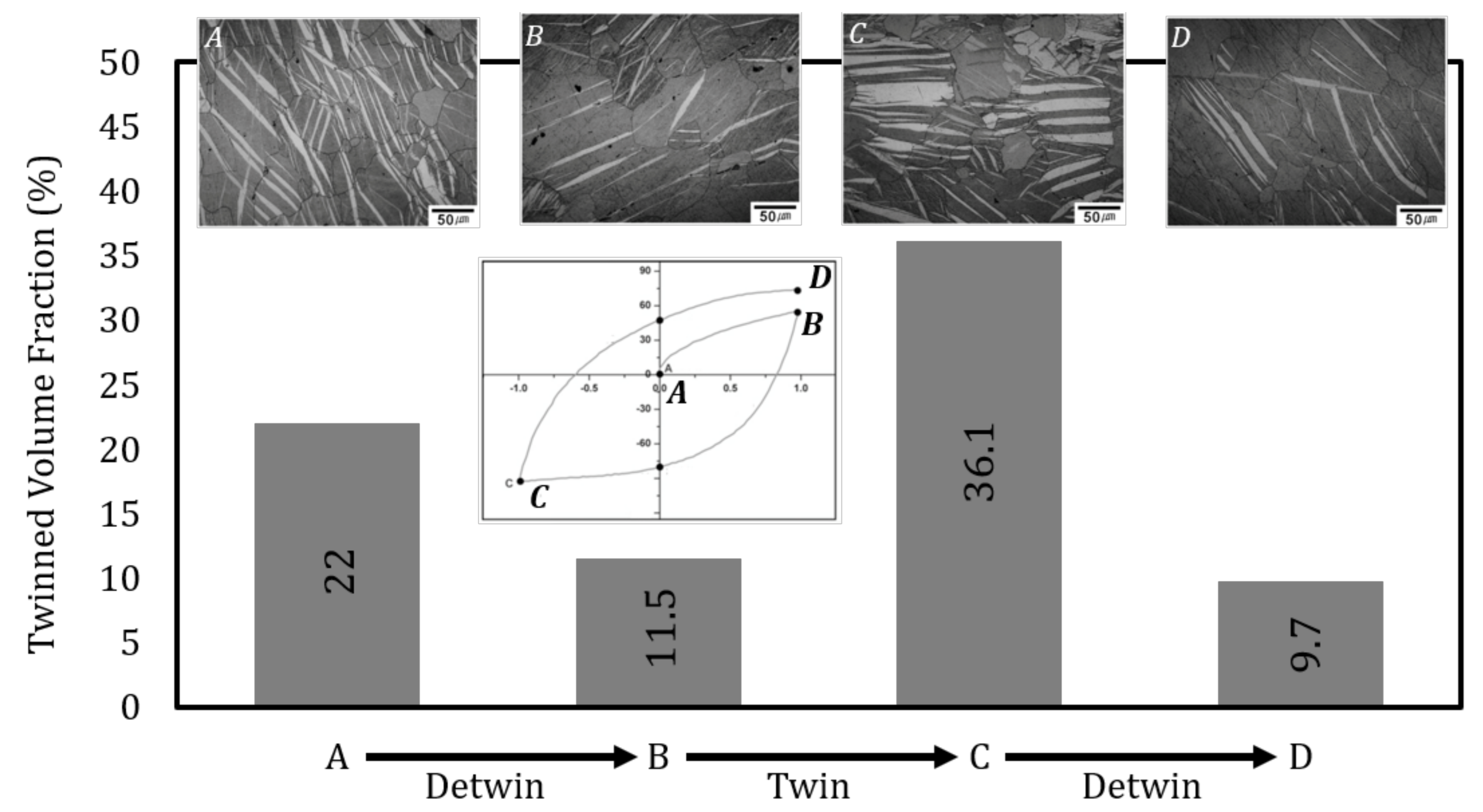
Recent digital image correlation by the present authors emphasized substantial pseudoelasticity upon stress removal during three–point bending, which resulted from significant untwinning behavior. This extensive untwinning, not seen in simple compression or tension, is associated with the significant fraction of stopped elastic–twins in Garber’s notation as autocatalysis phenomena are arrested at the neutral axis, whereupon accommodation effects are not complete. Not capturing this phenomenon in crystal plasticity would result in significant errors in spring–back predictions for sheet-forming operations.
6.
Twin nucleation mechanisms exhibit the necessity for current crystal plasticity models to incorporate the combined effects of shear and shuffle during twin nucleation events. Few advances in site–specific nucleation criterion based on probabilistic and dissociation-based methods are discussed along with the preliminary results for twinning site–selection based on hydrostatic stress gradients.

Author Contributions

Conceptualization, Y.P.; Investigation, Y.P., D.G., C.D.B., M.W.P., K.I. and H.E.K.; Resources, H.E.K., M.A.T. and H.R.; Supervision, M.W.P., C.D.B., K.I. and M.A.T.; Validation, M.W.P., C.D.B., K.I., M.A.T. and H.E.K.; Writing—original draft, Y.P. and D.G.; Writing—review and editing, Y.P., D.G., M.W.P., C.D.B., K.I., M.A.T., H.R. and H.E.K. All authors have read and agreed to the published version of the manuscript.

Funding

Research was sponsored by the Army Research Laboratory and was accomplished under the Cooperative Agreement Number W911NF-15-2-0025. The views and conclusions contained in this document are those of the authors and should not be interpreted as representing the official policies, either expressed or implied, of the Army Research Laboratory or the U.S. Government. The U.S. Government is authorized to reproduce and distribute reprints for Government purposes notwithstanding any copyright notation herein.

Institutional Review Board Statement

Not applicable.

Informed Consent Statement

Not applicable.

Conflicts of Interest

The authors declare no conflict of interest. The funders had no role in the design of the study; in the collection, analyses, or interpretation of data; in the writing of the manuscript, or in the decision to publish the results.

References

  1. Lebensohn, R.; Tomé, C. A study of the stress state associated with twin nucleation and propagation in anisotropic materials. Philos. Mag. A 1993, 67, 187–206. [Google Scholar] [CrossRef]
  2. Lebensohn, R.; Tomé, C. A self-consistent viscoplastic model: Prediction of rolling textures of anisotropic polycrystals. Mater. Sci. Eng. A 1994, 175, 71–82. [Google Scholar] [CrossRef] [Green Version]
  3. Lebensohn, R.A. N-site modeling of a 3D viscoplastic polycrystal using fast Fourier transform. Acta Mater. 2001, 49, 2723–2737. [Google Scholar] [CrossRef]
  4. Proust, G.; Tomé, C.; Kaschner, G. Modeling texture, twinning and hardening evolution during deformation of hexagonal materials. Acta Mater. 2007, 55, 2137–2148. [Google Scholar] [CrossRef]
  5. Van Houtte, P. Simulation of the rolling and shear texture of brass by the Taylor theory adapted for mechanical twinning. Acta Metall. 1978, 26, 591–604. [Google Scholar] [CrossRef]
  6. Tomé, C.; Lebensohn, R.; Kocks, U. A model for texture development dominated by deformation twinning: Application to zirconium alloys. Acta Metall. Et Mater. 1991, 39, 2667–2680. [Google Scholar] [CrossRef] [Green Version]
  7. Kalidindi, S.R. Incorporation of deformation twinning in crystal plasticity models. J. Mech. Phys. Solids 1998, 46, 267–290. [Google Scholar] [CrossRef]
  8. Salem, A.; Kalidindi, S.; Semiatin, S. Strain hardening due to deformation twinning in α-titanium: Constitutive relations and crystal-plasticity modeling. Acta Mater. 2005, 53, 3495–3502. [Google Scholar] [CrossRef]
  9. Lévesque, J.; Inal, K.; Neale, K.W.; Mishra, R. Numerical modeling of formability of extruded magnesium alloy tubes. Int. J. Plast. 2010, 26, 65–83. [Google Scholar] [CrossRef]
  10. Beyerlein, I.; Tomé, C. A dislocation-based constitutive law for pure Zr including temperature effects. Int. J. Plast. 2008, 24, 867–895. [Google Scholar] [CrossRef]
  11. Wang, H.; Wu, P.; Tomé, C.; Wang, J. A constitutive model of twinning and detwinning for hexagonal close packed polycrystals. Mater. Sci. Eng. A 2012, 555, 93–98. [Google Scholar] [CrossRef]
  12. Wu, P.; Guo, X.; Qiao, H.; Lloyd, D. A constitutive model of twin nucleation, propagation and growth in magnesium crystals. Mater. Sci. Eng. A 2015, 625, 140–145. [Google Scholar] [CrossRef]
  13. Segurado, J.; Lebensohn, R.A.; LLorca, J. Computational Homogenization of Polycrystals. arXiv 2018, arXiv:1804.02538. [Google Scholar]
  14. Beyerlein, I.J.; Knezevic, M. Review of microstructure and micromechanism-based constitutive modeling of polycrystals with a low-symmetry crystal structure. J. Mater. Res. 2018, 33, 3711–3738. [Google Scholar] [CrossRef]
  15. El Kadiri, H.; Barrett, C.D.; Wang, J.; Tomé, C.N. Why are twins profuse in magnesium? Acta Mater. 2015, 85, 354–361. [Google Scholar] [CrossRef] [Green Version]
  16. Barrett, C.D.; El Kadiri, H. Impact of deformation faceting on { 1 0 1 ¯ 2 } , { 1 0 1 ¯ 1 } , and { 1 0 1 ¯ 3 } embryonic twin nucleation in hexagonal close–packed metals. Acta Mater. 2014, 70, 137–161. [Google Scholar] [CrossRef]
  17. Wang, J.; Hoagland, R.; Hirth, J.; Capolungo, L.; Beyerlein, I.; Tomé, C. Nucleation of a ( 1 ¯ 0 1 2 ) twin in hexagonal close–packed crystals. Scr. Mater. 2009, 61, 903–906. [Google Scholar] [CrossRef]
  18. Wang, J.; Hirth, J.; Tomé, C. ( 1 0 1 ¯ 2 ) Twinning nucleation mechanisms in hexagonal-close–packed crystals. Acta Mater. 2009, 57, 5521–5530. [Google Scholar] [CrossRef]
  19. Serra, A.; Bacon, D. Computer simulation of twinning dislocation in magnesium using a many-body potential. Philos. Mag. A 1991, 63, 1001–1012. [Google Scholar] [CrossRef]
  20. Serra, A.; Pond, R.; Bacon, D. Computer simulation of the structure and mobility of twinning disclocations in hcp metals. Acta Metall. Et Mater. 1991, 39, 1469–1480. [Google Scholar] [CrossRef]
  21. Serra, A.; Bacon, D. A new model for { 1 0 1 2 } twin growth in hcp metals. Philos. Mag. A 1996, 73, 333–343. [Google Scholar] [CrossRef]
  22. Serra, A.; Bacon, D.; Pond, R. Twins as barriers to basal slip in hexagonal-close–packed metals. Metall. Mater. Trans. A 2002, 33, 809–812. [Google Scholar] [CrossRef]
  23. Christian, J.W.; Mahajan, S. Deformation twinning. Prog. Mater. Sci. 1995, 39, 1–157. [Google Scholar] [CrossRef]
  24. Kiho, H. The crystallographic aspect of the mechanical twinning in Ti and α-U. J. Phys. Soc. Jpn. 1958, 13, 269–272. [Google Scholar] [CrossRef]
  25. El Kadiri, H.; Barrett, C.D.; Tschopp, M.A. The candidacy of shuffle and shear during compound twinning in hexagonal close–packed structures. Acta Mater. 2013, 61, 7646–7659. [Google Scholar] [CrossRef] [Green Version]
  26. Mahajan, S. Critique of mechanisms of formation of deformation, annealing and growth twins: Face–centered cubic metals and alloys. Scr. Mater. 2013, 68, 95–99. [Google Scholar] [CrossRef]
  27. Capolungo, L.; Beyerlein, I. Nucleation and stability of twins in hcp metals. Phys. Rev. B 2008, 78, 024117. [Google Scholar] [CrossRef]
  28. Bell, R.; Cahn, R. The nucleation problem in deformation twinning. Acta Metall. 1953, 1, 752–753. [Google Scholar] [CrossRef]
  29. Cottrell, A.; Bilby, B. LX. A mechanism for the growth of deformation twins in crystals. Lond. Edinb. Dublin Philos. Mag. J. Sci. 1951, 42, 573–581. [Google Scholar] [CrossRef]
  30. Thompson, N.; Millard, D. XXXVIII. Twin formation, in cadmium. Lond. Edinb. Dublin Philos. Mag. J. Sci. 1952, 43, 422–440. [Google Scholar] [CrossRef]
  31. Capolungo, L.; Marshall, P.; McCabe, R.; Beyerlein, I.; Tomé, C. Nucleation and growth of twins in Zr: A statistical study. Acta Mater. 2009, 57, 6047–6056. [Google Scholar] [CrossRef]
  32. Beyerlein, I.; Tomé, C. A probabilistic twin nucleation model for HCP polycrystalline metals. In Proceedings of the Royal Society of London A: Mathematical, Physical and Engineering Science; The Royal Society: London, UK, 2010; p. rspa20090661. [Google Scholar]
  33. Beyerlein, I.; Capolungo, L.; Marshall, P.; McCabe, R.; Tomé, C. Statistical analyses of deformation twinning in magnesium. Philos. Mag. 2010, 90, 2161–2190. [Google Scholar] [CrossRef]
  34. Wang, J.; Beyerlein, I.; Tomé, C. An atomic and probabilistic perspective on twin nucleation in Mg. Scr. Mater. 2010, 63, 741–746. [Google Scholar] [CrossRef]
  35. Orowan, E. Dislocations in metals. AIME N. Y. 1954, 131. [Google Scholar]
  36. Price, P. Nucleation and growth of twins in dislocation-free zinc crystals. Proc. R. Soc. Lond. A Math. Phys. Eng. Sci. 1961, 260, 251–262. [Google Scholar]
  37. Barrett, C.; Kadiri, H.E.; Tschopp, M. Breakdown of the Schmid law in homogeneous and heterogeneous nucleation events of slip and twinning in magnesium. J. Mech. Phys. Solids 2012, 60, 2084–2099. [Google Scholar] [CrossRef]
  38. Stephenson, G.B. Deformation during interdiffusion. Acta Met. 1988, 36, 2663–2683. [Google Scholar] [CrossRef]
  39. Bell, R.L.; Cahn, R. The dynamics of twinning and the interrelation of slip and twinning in zinc crystals. Proc. R. Soc. Lond. A Math. Phys. Eng. Sci. 1957, 239, 494–521. [Google Scholar]
  40. Lay, S.; Nouet, G. Morphology of (01· 2) twins in zinc and related interfacial defects. Philos. Mag. A 1995, 72, 603–617. [Google Scholar] [CrossRef]
  41. Bilby, B.; Entwisle, A. The formation of mechanical twins. Acta Metall. 1954, 2, 15–19. [Google Scholar] [CrossRef]
  42. Chyung, C.K.; Wei, C.T. Nucleation of deformation twins in zinc bicrystals. Philos. Mag. 1967, 15, 161–175. [Google Scholar] [CrossRef]
  43. Zhang, J.; Xi, G.; Wan, X.; Fang, C. The dislocation-twin interaction and evolution of twin boundary in AZ31 Mg alloy. Acta Mater. 2017, 133, 208–216. [Google Scholar] [CrossRef]
  44. Meyers, M.; Vöhringer, O.; Lubarda, V. The onset of twinning in metals: A constitutive description. Acta Mater. 2001, 49, 4025–4039. [Google Scholar] [CrossRef]
  45. Fischer, F.; Appel, F.; Clemens, H. A thermodynamical model for the nucleation of mechanical twins in TiAl. Acta Mater. 2003, 51, 1249–1260. [Google Scholar] [CrossRef]
  46. Fischer, F.; Schaden, T.; Appel, F.; Clemens, H. Mechanical twins, their development and growth. Eur. J. Mech.-A/Solids 2003, 22, 709–726. [Google Scholar] [CrossRef]
  47. Fischer, F.D.; Schaden, T.; Appel, F.; Clemens, H. Continuum mechanics of deformation twinning–a review. Multidiscip. Model. Mater. Struct. 2006, 2, 167–187. [Google Scholar] [CrossRef]
  48. Fischer, F.; Antretter, T.; Oberaigner, E. Mechanics of sheared bands–Applications to faults, twins and variants. Mech. Mater. 2008, 40, 195–205. [Google Scholar] [CrossRef]
  49. Hooshmand, M.; Mills, M.; Ghazisaeidi, M. Atomistic modeling of dislocation interactions with twin boundaries in Ti. Model. Simul. Mater. Sci. Eng. 2017, 25, 045003. [Google Scholar] [CrossRef]
  50. Wang, J.; Yadav, S.; Hirth, J.; Tomé, C.; Beyerlein, I. Pure–shuffle nucleation of deformation twins in hexagonal-close–packed metals. Mater. Res. Lett. 2013, 1, 126–132. [Google Scholar] [CrossRef] [Green Version]
  51. Ghazisaeidi, M.; Curtin, W. Analysis of dissociation of 〈c〉 and 〈c + a〉 dislocations to nucleate twins in Mg. Model. Simul. Mater. Sci. Eng. 2013, 21, 055007. [Google Scholar]
  52. Kumar, A.; Wang, J.; Tomé, C.N. First-principles study of energy and atomic solubility of twinning-associated boundaries in hexagonal metals. Acta Mater. 2015, 85, 144–154. [Google Scholar] [CrossRef] [Green Version]
  53. Kresse, G.; Hafner, J. Ab initio molecular dynamics for liquid metals. Phys. Rev. B 1993, 47, 558. [Google Scholar] [CrossRef]
  54. Kresse, G.; Furthmüller, J. Efficiency of ab–initio total energy calculations for metals and semiconductors using a plane-wave basis set. Comput. Mater. Sci. 1996, 6, 15–50. [Google Scholar] [CrossRef]
  55. Kresse, G.; Furthmüller, J. Efficient iterative schemes for ab initio total-energy calculations using a plane-wave basis set. Phys. Rev. B 1996, 54, 11169. [Google Scholar] [CrossRef]
  56. Xu, H.L.; Su, X.M.; Yuan, G.Y.; Jin, Z.H. Primary and secondary modes of deformation twinning in HCP Mg based on atomistic simulations. Trans. Nonferr. Met. Soc. China 2014, 24, 3804–3809. [Google Scholar] [CrossRef]
  57. Ecob, N.; Ralph, B. The effect of grain size on deformation twinning in a textured zinc alloy. J. Mater. Sci. 1983, 18, 2419–2429. [Google Scholar] [CrossRef]
  58. Barnett, M.; Keshavarz, Z.; Beer, A.; Atwell, D. Influence of grain size on the compressive deformation of wrought Mg–3Al–1Zn. Acta Mater. 2004, 52, 5093–5103. [Google Scholar] [CrossRef]
  59. Barnett, M.R.; Nave, M.D.; Ghaderi, A. Yield point elongation due to twinning in a magnesium alloy. Acta Mater. 2012, 60, 1433–1443. [Google Scholar] [CrossRef]
  60. Barnett, M.R.; Stanford, N.; Ghaderi, A.; Siska, F. Plastic relaxation of the internal stress induced by twinning. Acta Mater. 2013, 61, 7859–7867. [Google Scholar] [CrossRef]
  61. Muránsky, O.; Barnett, M.; Luzin, V.; Vogel, S. On the correlation between deformation twinning and Lüders-like deformation in an extruded Mg alloy: In situ neutron diffraction and EPSC. 4 modelling. Mater. Sci. Eng. A 2010, 527, 1383–1394. [Google Scholar] [CrossRef]
  62. Muránsky, O.; Barnett, M.; Carr, D.; Vogel, S.; Oliver, E. Investigation of deformation twinning in a fine–grained and coarse-grained ZM20 Mg alloy: Combined in situ neutron diffraction and acoustic emission. Acta Mater. 2010, 58, 1503–1517. [Google Scholar] [CrossRef]
  63. Antonopoulos, J.; Karakostas, T.; Komninou, P.; Delavignette, P. Dislocation movements and deformation twinning in zinc. Acta Metall. 1988, 36, 2493–2502. [Google Scholar] [CrossRef]
  64. Barnett, M.; Keshavarz, Z.; Beer, A.; Ma, X. Non-Schmid behaviour during secondary twinning in a polycrystalline magnesium alloy. Acta Mater. 2008, 56, 5–15. [Google Scholar] [CrossRef]
  65. Capolungo, L.; Beyerlein, I.; Kaschner, G.; Tomé, C. On the interaction between slip dislocations and twins in HCP Zr. Mater. Sci. Eng. A 2009, 513, 42–51. [Google Scholar] [CrossRef]
  66. Wang, F.; Agnew, S.R. Dislocation transmutation by tension twinning in magnesium alloy AZ31. Int. J. Plast. 2016, 81, 63–86. [Google Scholar] [CrossRef] [Green Version]
  67. Tang, X.Z.; Zu, Q.; Guo, Y.F. The diffusive character of extension twin boundary migration in magnesium. Materialia 2018, 2, 208–213. [Google Scholar] [CrossRef]
  68. Paudel, Y.; Barrett, C.D.; Tschopp, M.; Inal, K.; El Kadiri, H. Beyond initial twin nucleation in hcp metals: Micromechanical formulation for determining twin spacing during deformation. Acta Mater. 2017, 133, 134–146. [Google Scholar] [CrossRef]
  69. Siska, F.; Stratil, L.; Cizek, J.; Ghaderi, A.; Barnett, M. Numerical analysis of twin thickening process in magnesium alloys. Acta Mater. 2017, 124, 9–16. [Google Scholar] [CrossRef]
  70. Giri, D.; Barrett, C.D.; El Kadiri, H. Measurement of twin formation energy barriers using nudged elastic band molecular statics. In TMS Annual Meeting & Exhibition; Springer: Cham, Switzerland, 2018; pp. 231–236. [Google Scholar] [CrossRef]
  71. Giri, D.; El Kadiri, H.; Limmer, K.R.; Barrett, C.D. An atomistic gateway into capturing twin nucleation in crystal plasticity. Philos. Mag. Lett. 2020, 100, 375–385. [Google Scholar] [CrossRef]
  72. Lloyd, J. A dislocation-based model for twin growth within and across grains. Proc. R. Soc. A 2018, 474, 20170709. [Google Scholar] [CrossRef] [Green Version]
  73. Taylor, G.I.; Elam, C.F. Bakerian lecture. The distortion of an aluminium crystal during a tensile test. Proc. R. Soc. Lond. A Math. Phys. Eng. Sci. 1923, 102, 643–667. [Google Scholar]
  74. Taylor, G.; Elam, C. The plastic extension and fracture of aluminium crystals. Proc. R. Soc. Lond. Ser. A Contain. Pap. A Math. Phys. Character 1925, 108, 28–51. [Google Scholar]
  75. Taylor, G. Plastic strain in metals. J. Inst. Met. 1938, 62, 307–324. [Google Scholar]
  76. Taylor, G.I. Analysis of plastic strain in a cubic crystal. Stephen Timoshenko 60th Anniversary Volume; The Macmillan Company: New York, NY, USA, 1938; pp. 218–224. [Google Scholar]
  77. Mandel, J. Généralisation de la théorie de plasticité de WT Koiter. Int. J. Solids Struct. 1965, 1, 273–295. [Google Scholar] [CrossRef]
  78. Hill, R. Generalized constitutive relations for incremental deformation of metal crystals by multislip. J. Mech. Phys. Solids 1966, 14, 95–102. [Google Scholar] [CrossRef]
  79. Rice, J.R. Inelastic constitutive relations for solids: An internal-variable theory and its application to metal plasticity. J. Mech. Phys. Solids 1971, 19, 433–455. [Google Scholar] [CrossRef]
  80. Hill, R.; Rice, J. Constitutive analysis of elastic–plastic crystals at arbitrary strain. J. Mech. Phys. Solids 1972, 20, 401–413. [Google Scholar] [CrossRef]
  81. Anand, L.; Kothari, M. A computational procedure for rate-independent crystal plasticity. J. Mech. Phys. Solids 1996, 44, 525–558. [Google Scholar] [CrossRef]
  82. Peirce, D.; Asaro, R.; Needleman, A. An analysis of nonuniform and localized deformation in ductile single crystals. Acta Metall. 1982, 30, 1087–1119. [Google Scholar] [CrossRef]
  83. Peirce, D.; Asaro, R.J.; Needleman, A. Material rate dependence and localized deformation in crystalline solids. Acta Metall. 1983, 31, 1951–1976. [Google Scholar] [CrossRef]
  84. Asaro, R.J.; Needleman, A. Overview no. 42 Texture development and strain hardening in rate dependent polycrystals. Acta Metall. 1985, 33, 923–953. [Google Scholar] [CrossRef]
  85. Kalidindi, S.R.; Bronkhorst, C.A.; Anand, L. Crystallographic texture evolution in bulk deformation processing of FCC metals. J. Mech. Phys. Solids 1992, 40, 537–569. [Google Scholar] [CrossRef]
  86. Remy, L. The interaction between slip and twinning systems and the influence of twinning on the mechanical behavior of fcc metals and alloys. Metall. Mater. Trans. A 1981, 12, 387–408. [Google Scholar] [CrossRef]
  87. Singh, R.p.; Doherty, R.D. Strengthening in multiphase (MP35N) alloy: Part I. Ambient temperature deformation and recrystallization. Metall. Mater. Trans. A 1992, 23, 307–319. [Google Scholar] [CrossRef]
  88. Asgari, S.; El-Danaf, E.; Kalidindi, S.R.; Doherty, R.D. Strain hardening regimes and microstructural evolution during large strain compression of low stacking fault energy fcc alloys that form deformation twins. Metall. Mater. Trans. A 1997, 28, 1781–1795. [Google Scholar] [CrossRef]
  89. Heye, W.; Wassermann, G. The formation of the rolling textures of the face-centered cubic metals by means of slip, twinning and development of limited fiber textures—I. Formation of rolling textures by means of slip (copper texture). Z METALLKD 1968, 59, 617–624. [Google Scholar]
  90. Duggan, B.; Hatherly, M.; Hutchinson, W.; Wakefield, P. Deformation structures and textures in cold–rolled 70: 30 brass. Met. Sci. 1978, 12, 343–351. [Google Scholar] [CrossRef]
  91. Hirsch, J.; Lücke, K.; Hatherly, M. Overview No. 76: Mechanism of deformation and development of rolling textures in polycrystalline fcc Metals—III. The influence of slip inhomogeneities and twinning. Acta Metall. 1988, 36, 2905–2927. [Google Scholar] [CrossRef]
  92. Chin, G.; Hosford, W.; Mendorf, D. Accommodation of constrained deformation in fcc metals by slip and twinning. Proc. R. Soc. Lond. A Math. Phys. Eng. Sci. 1969, 309, 433–456. [Google Scholar]
  93. Staroselsky, A.; Anand, L. A constitutive model for hcp materials deforming by slip and twinning: Application to magnesium alloy AZ31B. Int. J. Plast. 2003, 19, 1843–1864. [Google Scholar] [CrossRef]
  94. Kalidindi, S.R. Modeling anisotropic strain hardening and deformation textures in low stacking fault energy fcc metals. Int. J. Plast. 2001, 17, 837–860. [Google Scholar] [CrossRef]
  95. Wu, X.; Kalidindi, S.R.; Necker, C.; Salem, A.A. Prediction of crystallographic texture evolution and anisotropic stress–strain curves during large plastic strains in high purity α-titanium using a Taylor-type crystal plasticity model. Acta Mater. 2007, 55, 423–432. [Google Scholar] [CrossRef]
  96. Clausen, B.; Tomé, C.; Brown, D.; Agnew, S. Reorientation and stress relaxation due to twinning: Modeling and experimental characterization for Mg. Acta Mater. 2008, 56, 2456–2468. [Google Scholar] [CrossRef]
  97. Knezevic, M.; Levinson, A.; Harris, R.; Mishra, R.K.; Doherty, R.D.; Kalidindi, S.R. Deformation twinning in AZ31: Influence on strain hardening and texture evolution. Acta Mater. 2010, 58, 6230–6242. [Google Scholar] [CrossRef]
  98. Inal, K.; Neale, K.; Aboutajeddine, A. Forming limit comparisons for FCC and BCC sheets. Int. J. Plast. 2005, 21, 1255–1266. [Google Scholar] [CrossRef]
  99. Izadbakhsh, A.; Inal, K.; Mishra, R.K.; Niewczas, M. New crystal plasticity constitutive model for large strain deformation in single crystals of magnesium. Comput. Mater. Sci. 2011, 50, 2185–2202. [Google Scholar] [CrossRef]
  100. Abdolvand, H.; Daymond, M.R. Internal strain and texture development during twinning: Comparing neutron diffraction measurements with crystal plasticity finite-element approaches. Acta Mater. 2012, 60, 2240–2248. [Google Scholar] [CrossRef]
  101. Abdolvand, H.; Daymond, M.R. Multi-scale modeling and experimental study of twin inception and propagation in hexagonal close-packed materials using a crystal plasticity finite element approach; part II: Local behavior. J. Mech. Phys. Solids 2013, 61, 803–818. [Google Scholar] [CrossRef]
  102. Abdolvand, H.; Majkut, M.; Oddershede, J.; Wright, J.P.; Daymond, M.R. Study of 3-D stress development in parent and twin pairs of a hexagonal close-packed polycrystal: Part II—Crystal plasticity finite element modeling. Acta Mater. 2015, 93, 235–245. [Google Scholar] [CrossRef]
  103. Tomé, C.; Maudlin, P.; Lebensohn, R.; Kaschner, G. Mechanical response of zirconium—I. Derivation of a polycrystal constitutive law and finite element analysis. Acta Mater. 2001, 49, 3085–3096. [Google Scholar] [CrossRef]
  104. Segurado, J.; Lebensohn, R.A.; LLorca, J.; Tomé, C.N. Multiscale modeling of plasticity based on embedding the viscoplastic self-consistent formulation in implicit finite elements. Int. J. Plast. 2012, 28, 124–140. [Google Scholar] [CrossRef]
  105. Herrera-Solaz, V.; LLorca, J.; Dogan, E.; Karaman, I.; Segurado, J. An inverse optimization strategy to determine single crystal mechanical behavior from polycrystal tests: Application to AZ31 Mg alloy. Int. J. Plast. 2014, 57, 1–15. [Google Scholar] [CrossRef] [Green Version]
  106. Prakash, A.; Nöhring, W.; Lebensohn, R.; Höppel, H.; Bitzek, E. A multiscale simulation framework of the accumulative roll bonding process accounting for texture evolution. Mater. Sci. Eng. A 2015, 631, 104–119. [Google Scholar] [CrossRef]
  107. Wu, P.; Van Der Giessen, E. On improved network models for rubber elasticity and their applications to orientation hardening in glassy polymers. J. Mech. Phys. Solids 1993, 41, 427–456. [Google Scholar] [CrossRef] [Green Version]
  108. Wu, P.; van der Giessen, E. Analysis of shear band propagation in amorphous glassy polymers. Int. J. Solids Struct. 1994, 31, 1493–1517. [Google Scholar] [CrossRef] [Green Version]
  109. Cheng, J.; Ghosh, S. A crystal plasticity FE model for deformation with twin nucleation in magnesium alloys. Int. J. Plast. 2015, 67, 148–170. [Google Scholar] [CrossRef]
  110. Cheng, J.; Ghosh, S. Crystal plasticity finite element modeling of discrete twin evolution in polycrystalline magnesium. J. Mech. Phys. Solids 2017, 99, 512–538. [Google Scholar] [CrossRef] [Green Version]
  111. Ardeljan, M.; McCabe, R.J.; Beyerlein, I.J.; Knezevic, M. Explicit incorporation of deformation twins into crystal plasticity finite element models. Comput. Methods Appl. Mech. Eng. 2015, 295, 396–413. [Google Scholar] [CrossRef] [Green Version]
  112. Ardeljan, M.; Beyerlein, I.J.; Knezevic, M. Effect of dislocation density-twin interactions on twin growth in AZ31 as revealed by explicit crystal plasticity finite element modeling. Int. J. Plast. 2017, 99, 81–101. [Google Scholar] [CrossRef]
  113. Ardeljan, M.; Knezevic, M. Explicit modeling of double twinning in AZ31 using crystal plasticity finite elements for predicting the mechanical fields for twin variant selection and fracture analyses. Acta Mater. 2018, 157, 339–354. [Google Scholar] [CrossRef]
  114. Qiao, H.; Barnett, M.; Wu, P. Modeling of twin formation, propagation and growth in a Mg single crystal based on crystal plasticity finite element method. Int. J. Plast. 2016, 86, 70–92. [Google Scholar] [CrossRef]
  115. Lévesque, J.; Mohammadi, M.; Mishra, R.K.; Inal, K. An extended Taylor model to simulate localized deformation phenomena in magnesium alloys. Int. J. Plast. 2016, 78, 203–222. [Google Scholar] [CrossRef]
  116. Wang, H.; Wu, P.; Wang, J.; Tomé, C. A crystal plasticity model for hexagonal close packed (HCP) crystals including twinning and de-twinning mechanisms. Int. J. Plast. 2013, 49, 36–52. [Google Scholar] [CrossRef]
  117. Hong, S.G.; Park, S.H.; Lee, C.S. Enhancing the fatigue property of rolled AZ31 magnesium alloy by controlling {1012} twinning-detwinning characteristics. J. Mater. Res. 2010, 25, 784–792. [Google Scholar] [CrossRef]
  118. Proust, G.; Tomé, C.N.; Jain, A.; Agnew, S.R. Modeling the effect of twinning and detwinning during strain-path changes of magnesium alloy AZ31. Int. J. Plast. 2009, 25, 861–880. [Google Scholar] [CrossRef]
  119. Knezevic, M.; Zecevic, M.; Beyerlein, I.J.; Bingert, J.F.; McCabe, R.J. Strain rate and temperature effects on the selection of primary and secondary slip and twinning systems in HCP Zr. Acta Mater. 2015, 88, 55–73. [Google Scholar] [CrossRef] [Green Version]
  120. Canova, G.; Wenk, H.; Molinari, A. Deformation modelling of multi-phase polycrystals: Case of a quartz-mica aggregate. Acta Metall. Et Mater. 1992, 40, 1519–1530. [Google Scholar] [CrossRef]
  121. Solas, D.; Tomé, C. Texture and strain localization prediction using a N-site polycrystal model. Int. J. Plast. 2001, 17, 737–753. [Google Scholar] [CrossRef]
  122. Becker, R.; Richmond, O. Incorporation of microstructural geometry in material modelling. Model. Simul. Mater. Sci. Eng. 1994, 2, 439. [Google Scholar] [CrossRef]
  123. Turner, P.; Tomé, C. A study of residual stresses in Zircaloy-2 with rod texture. Acta Metall. Et Mater. 1994, 42, 4143–4153. [Google Scholar] [CrossRef]
  124. Lebensohn, R.A.; Brenner, R.; Castelnau, O.; Rollett, A.D. Orientation image-based micromechanical modelling of subgrain texture evolution in polycrystalline copper. Acta Mater. 2008, 56, 3914–3926. [Google Scholar] [CrossRef]
  125. Prakash, A.; Weygand, S.; Riedel, H. Modeling the evolution of texture and grain shape in Mg alloy AZ31 using the crystal plasticity finite element method. Comput. Mater. Sci. 2009, 45, 744–750. [Google Scholar] [CrossRef]
  126. Moulinec, H.; Suquet, P. A numerical method for computing the overall response of nonlinear composites with complex microstructure. Comput. Methods Appl. Mech. Eng. 1998, 157, 69–94. [Google Scholar] [CrossRef]
  127. Michel, J.; Moulinec, H.; Suquet, P. A computational method based on augmented Lagrangians and fast Fourier transforms for composites with high contrast. CMES Comput. Model. Eng. Sci. 2000, 1, 79–88. [Google Scholar]
  128. Hutchinson, J. Bounds and self-consistent estimates for creep of polycrystalline materials. Proc. R. Soc. Lond. A Math. Phys. Eng. Sci. 1976, 348, 101–127. [Google Scholar]
  129. Molinari, A.; Canova, G.; Ahzi, S. A self consistent approach of the large deformation polycrystal viscoplasticity. Acta Metall. 1987, 35, 2983–2994. [Google Scholar] [CrossRef]
  130. Lebensohn, R.; Tomé, C. A self-consistent anisotropic approach for the simulation of plastic deformation and texture development of polycrystals: Application to zirconium alloys. Acta Metall. Et Mater. 1993, 41, 2611–2624. [Google Scholar] [CrossRef]
  131. Lebensohn, R.; Liu, Y.; Castaneda, P.P. Macroscopic properties and field fluctuations in model power-law polycrystals: Full-field solutions versus self-consistent estimates. Proc. R. Soc. Lond. A Math. Phys. Eng. Sci. 2004, 460, 1381–1405. [Google Scholar] [CrossRef]
  132. Moulinec, H.; Suquet, P. A fast numerical method for computing the linear and nonlinear mechanical properties of composites. Comptes Rendus L’Acad. Sci. Série II Méc. Phys. Chim. Astron. 1994, 318, 1417–1423. [Google Scholar]
  133. Michel, J.; Moulinec, H.; Suquet, P. Effective properties of composite materials with periodic microstructure: A computational approach. Comput. Methods Appl. Mech. Eng. 1999, 172, 109–143. [Google Scholar] [CrossRef]
  134. Rollett, A.D.; Wagner, F.; Allain-Bonasso, N.; Field, D.P.; Lebensohn, R.A. Comparison of gradients in orientation and stress between experiment and simulation. Mater. Sci. Forum 2012, 702, 463–468. [Google Scholar] [CrossRef]
  135. Lebensohn, R.A.; Needleman, A. Numerical implementation of non-local polycrystal plasticity using fast Fourier transforms. J. Mech. Phys. Solids 2016, 97, 333–351. [Google Scholar] [CrossRef]
  136. Kumar, M.A.; Kanjarla, A.; Niezgoda, S.; Lebensohn, R.; Tomé, C. Numerical study of the stress state of a deformation twin in magnesium. Acta Mater. 2015, 84, 349–358. [Google Scholar] [CrossRef]
  137. Barnett, M.; Bouaziz, O.; Toth, L.S. A microstructure based analytical model for tensile twinning in a rod textured Mg alloy. Int. J. Plast. 2015, 72, 151–167. [Google Scholar] [CrossRef]
  138. Tari, V.; Rollett, A.D.; El Kadiri, H.; Beladi, H.; Oppedal, A.L.; King, R.L. The effect of deformation twinning on stress localization in a three dimensional TWIP steel microstructure. Model. Simul. Mater. Sci. Eng. 2015, 23, 045010. [Google Scholar] [CrossRef] [Green Version]
  139. Kumar, M.A.; Beyerlein, I.J.; Tomé, C.N. Effect of local stress fields on twin characteristics in HCP metals. Acta Mater. 2016, 116, 143–154. [Google Scholar] [CrossRef] [Green Version]
  140. Kumar, M.A.; Beyerlein, I.; McCabe, R.; Tomé, C. Grain neighbour effects on twin transmission in hexagonal close-packed materials. Nat. Commun. 2016, 7, 1–9. [Google Scholar]
  141. Kondo, R.; Tadano, Y.; Shizawa, K. A phase-field model of twinning and detwinning coupled with dislocation-based crystal plasticity for HCP metals. Comput. Mater. Sci. 2014, 95, 672–683. [Google Scholar] [CrossRef]
  142. Liu, C.; Shanthraj, P.; Diehl, M.; Roters, F.; Dong, S.; Dong, J.; Ding, W.; Raabe, D. An integrated crystal plasticity–phase field model for spatially resolved twin nucleation, propagation, and growth in hexagonal materials. Int. J. Plast. 2018, 106, 203–227. [Google Scholar] [CrossRef]
  143. Grilli, N.; Cocks, A.C.; Tarleton, E. A phase field model for the growth and characteristic thickness of deformation-induced twins. J. Mech. Phys. Solids 2020, 143, 104061. [Google Scholar] [CrossRef]
  144. Liu, G.; Mo, H.; Wang, J.; Shen, Y. Coupled crystal plasticity finite element-phase field model with kinetics-controlled twinning mechanism for hexagonal metals. Acta Mater. 2021, 202, 399–416. [Google Scholar] [CrossRef]
  145. Hu, X.; Ji, Y.; Chen, L.; Lebensohn, R.A.; Chen, L.Q.; Cui, X. Spectral phase-field model of deformation twinning and plastic deformation. Int. J. Plast. 2021, 143, 103019. [Google Scholar] [CrossRef]
  146. Khachaturian, A. Theory of Structural Transformations in Solids; Courier Corporation: Chelmsford, MA, USA, 1983. [Google Scholar]
  147. Paliwal, B.; Moser, R.D.; Barrett, C.D.; Whittington, W.R.; Rhee, H.; Paudel, Y.; Mujahid, S.; El Kadiri, H. Martensitic microstructure evolution in austenitic steel: A thermomechanical polycrystalline phase field study. J. Mater. Res. 2021, 36, 1376–1399. [Google Scholar] [CrossRef]
  148. Mamivand, M.; Zaeem, M.A.; El Kadiri, H. Shape memory effect and pseudoelasticity behavior in tetragonal zirconia polycrystals: A phase field study. Int. J. Plast. 2014, 60, 71–86. [Google Scholar] [CrossRef]
  149. Pi, Z.; Fang, Q.; Liu, B.; Feng, H.; Liu, Y.; Liu, Y.; Wen, P. A phase field study focuses on the transverse propagation of deformation twinning for hexagonal-closed packed crystals. Int. J. Plast. 2016, 76, 130–146. [Google Scholar] [CrossRef]
  150. Wu, P.; Neale, K.; Van der Giessen, E. Simulation of the behaviour of FCC polycrystals during reversed torsion. Int. J. Plast. 1996, 12, 1199–1219. [Google Scholar] [CrossRef] [Green Version]
  151. Lebensohn, R.A.; Kanjarla, A.K.; Eisenlohr, P. An elasto-viscoplastic formulation based on fast Fourier transforms for the prediction of micromechanical fields in polycrystalline materials. Int. J. Plast. 2012, 32, 59–69. [Google Scholar] [CrossRef]
  152. Lebensohn, R.; Turner, P.; Signorelli, J.; Canova, G.; Tomé, C. Calculation of intergranular stresses based on a large-strain viscoplastic self-consistent polycrystal model. Model. Simul. Mater. Sci. Eng. 1998, 6, 447. [Google Scholar] [CrossRef] [Green Version]
  153. Lebensohn, R. Modelling the role of local correlations in polycrystal plasticity using viscoplastic self-consistent schemes. Model. Simul. Mater. Sci. Eng. 1999, 7, 739. [Google Scholar] [CrossRef]
  154. Michel, J.; Moulinec, H.; Suquet, P. A computational scheme for linear and non-linear composites with arbitrary phase contrast. Int. J. Numer. Methods Eng. 2001, 52, 139–160. [Google Scholar] [CrossRef]
  155. Liu, B.; Raabe, D.; Roters, F.; Eisenlohr, P.; Lebensohn, R. Comparison of finite element and fast Fourier transform crystal plasticity solvers for texture prediction. Model. Simul. Mater. Sci. Eng. 2010, 18, 085005. [Google Scholar] [CrossRef]
  156. Mareau, C.; Daymond, M.R. Micromechanical modelling of twinning in polycrystalline materials: Application to magnesium. Int. J. Plast. 2016, 85, 156–171. [Google Scholar] [CrossRef] [Green Version]
  157. Asaro, R.J.; Rice, J. Strain localization in ductile single crystals. J. Mech. Phys. Solids 1977, 25, 309–338. [Google Scholar] [CrossRef] [Green Version]
  158. Izadbakhsh, A.; Inal, K.; Mishra, R.K. Numerical formability assessment in single crystals of magnesium. Comput. Mater. Sci. 2010, 50, 571–585. [Google Scholar] [CrossRef]
  159. Karaman, I.; Sehitoglu, H.; Beaudoin, A.; Chumlyakov, Y.I.; Maier, H.; Tome, C. Modeling the deformation behavior of Hadfield steel single and polycrystals due to twinning and slip. Acta Mater. 2000, 48, 2031–2047. [Google Scholar] [CrossRef] [Green Version]
  160. Kok, S.; Beaudoin, A.; Tortorelli, D. On the development of stage IV hardening using a model based on the mechanical threshold. Acta Mater. 2002, 50, 1653–1667. [Google Scholar] [CrossRef]
  161. Roberts, C.S. Magnesium and Its Alloys; John Wiley & Sons: New York, NY, USA, 1960. [Google Scholar]
  162. Wu, P.; Guo, X.; Qiao, H.; Agnew, S.; Lloyd, D.; Embury, J. On the rapid hardening and exhaustion of twinning in magnesium alloy. Acta Mater. 2017, 122, 369–377. [Google Scholar] [CrossRef] [Green Version]
  163. Wang, H.; Wu, P.; Tomé, C.; Huang, Y. A finite strain elastic–viscoplastic self-consistent model for polycrystalline materials. J. Mech. Phys. Solids 2010, 58, 594–612. [Google Scholar] [CrossRef]
  164. Madec, R.; Devincre, B.; Kubin, L.; Hoc, T.; Rodney, D. The role of collinear interaction in dislocation-induced hardening. Science 2003, 301, 1879–1882. [Google Scholar] [CrossRef]
  165. Bertin, N.; Tomé, C.; Beyerlein, I.; Barnett, M.; Capolungo, L. On the strength of dislocation interactions and their effect on latent hardening in pure magnesium. Int. J. Plast. 2014, 62, 72–92. [Google Scholar] [CrossRef]
  166. Mecking, H.; Kocks, U. Kinetics of flow and strain-hardening. Acta Metall. 1981, 29, 1865–1875. [Google Scholar] [CrossRef]
  167. Essmann, U.; Mughrabi, H. Annihilation of dislocations during tensile and cyclic deformation and limits of dislocation densities. Philos. Mag. A 1979, 40, 731–756. [Google Scholar] [CrossRef]
  168. Messner, M.C.; Rhee, M.; Arsenlis, A.; Barton, N.R. A crystal plasticity model for slip in hexagonal close packed metals based on discrete dislocation simulations. Model. Simul. Mater. Sci. Eng. 2017, 25, 044001. [Google Scholar] [CrossRef]
  169. Capolungo, L.; Beyerlein, I.; Tomé, C. Slip-assisted twin growth in hexagonal close-packed metals. Scr. Mater. 2009, 60, 32–35. [Google Scholar] [CrossRef]
  170. Hirth, J.P.; Lothe, J. Theory of Dislocations; Wiley: New York, NY, USA, 1982. [Google Scholar]
  171. Keshavarz, S.; Ghosh, S. Multi-scale crystal plasticity finite element model approach to modeling nickel-based superalloys. Acta Mater. 2013, 61, 6549–6561. [Google Scholar] [CrossRef]
  172. Yu, Q.; Shan, Z.W.; Li, J.; Huang, X.; Xiao, L.; Sun, J.; Ma, E. Strong crystal size effect on deformation twinning. Nature 2010, 463, 335. [Google Scholar] [CrossRef]
  173. Ghosh, S.; Cheng, J. Adaptive multi-time-domain subcycling for crystal plasticity FE modeling of discrete twin evolution. Comput. Mech. 2018, 61, 33–54. [Google Scholar] [CrossRef]
  174. Neil, C.J.; Agnew, S.R. Crystal plasticity-based forming limit prediction for non-cubic metals: Application to Mg alloy AZ31B. Int. J. Plast. 2009, 25, 379–398. [Google Scholar] [CrossRef]
  175. Lloyd, J.T.; Priddy, M.W. Simulating strain localization in rolled magnesium. Acta Mater. 2017, 129, 149–158. [Google Scholar] [CrossRef]
  176. Zhang, R.Y.; Daymond, M.R.; Holt, R.A. A finite element model of deformation twinning in zirconium. Mater. Sci. Eng. A 2008, 473, 139–146. [Google Scholar] [CrossRef]
  177. Zhang, R.Y.; Daymond, M.R.; Holt, R.A. Parametric study of stress state development during twinning using 3D finite element modeling. Mater. Sci. Eng. A 2011, 528, 2725–2735. [Google Scholar] [CrossRef]
  178. Grilli, N.; Tarleton, E.; Cocks, A.C. Coupling a discrete twin model with cohesive elements to understand twin-induced fracture. Int. J. Fract. 2021, 227, 173–192. [Google Scholar] [CrossRef]
  179. Brown, D.; Agnew, S.; Bourke, M.; Holden, T.; Vogel, S.; Tomé, C. Internal strain and texture evolution during deformation twinning in magnesium. Mater. Sci. Eng. A 2005, 399, 1–12. [Google Scholar] [CrossRef]
  180. Choi, S.H.; Kim, D.; Park, S.S.; You, B. Simulation of stress concentration in Mg alloys using the crystal plasticity finite element method. Acta Mater. 2010, 58, 320–329. [Google Scholar] [CrossRef]
  181. Choi, S.H.; Kim, D.; Lee, H.; Shin, E. Simulation of texture evolution and macroscopic properties in Mg alloys using the crystal plasticity finite element method. Mater. Sci. Eng. A 2010, 527, 1151–1159. [Google Scholar] [CrossRef]
  182. Choi, S.H.; Kim, D.; Seong, B.; Rollett, A. 3-D simulation of spatial stress distribution in an AZ31 Mg alloy sheet under in-plane compression. Int. J. Plast. 2011, 27, 1702–1720. [Google Scholar] [CrossRef]
  183. Popova, E.; Brahme, A.; Staraselski, Y.; Agnew, S.; Mishra, R.; Inal, K. Effect of extension twins on texture evolution at elevated temperature deformation accompanied by dynamic recrystallization. Mater. Des. 2016, 96, 446–457. [Google Scholar] [CrossRef] [Green Version]
  184. Agnew, S.; Yoo, M.; Tomé, C. Application of texture simulation to understanding mechanical behavior of Mg and solid solution alloys containing Li or Y. Acta Mater. 2001, 49, 4277–4289. [Google Scholar] [CrossRef]
  185. Jain, A.; Agnew, S. Modeling the temperature dependent effect of twinning on the behavior of magnesium alloy AZ31B sheet. Mater. Sci. Eng. A 2007, 462, 29–36. [Google Scholar] [CrossRef]
  186. Hyun, C.; Kim, M.; Choi, S.H.; Shin, K. Crystal plasticity FEM study of twinning and slip in a Mg single crystal by Erichsen test. Acta Mater. 2018, 156, 342–355. [Google Scholar] [CrossRef]
  187. Paramatmuni, C.; Kanjarla, A.K. A crystal plasticity FFT based study of deformation twinning, anisotropy and micromechanics in HCP materials: Application to AZ31 alloy. Int. J. Plast. 2019, 113, 269–290. [Google Scholar] [CrossRef]
  188. Kouchmeshky, B.; Zabaras, N. Modeling the response of HCP polycrystals deforming by slip and twinning using a finite element representation of the orientation space. Comput. Mater. Sci. 2009, 45, 1043–1051. [Google Scholar] [CrossRef]
  189. Zhang, Y.; Millett, P.C.; Tonks, M.; Biner, B. Deformation-twin-induced grain boundary failure. Scr. Mater. 2012, 66, 117–120. [Google Scholar] [CrossRef]
  190. Abdolvand, H.; Daymond, M.R.; Mareau, C. Incorporation of twinning into a crystal plasticity finite element model: Evolution of lattice strains and texture in Zircaloy-2. Int. J. Plast. 2011, 27, 1721–1738. [Google Scholar] [CrossRef]
  191. Knezevic, M.; Beyerlein, I.J.; Brown, D.W.; Sisneros, T.A.; Tomé, C.N. A polycrystal plasticity model for predicting mechanical response and texture evolution during strain-path changes: Application to beryllium. Int. J. Plast. 2013, 49, 185–198. [Google Scholar] [CrossRef]
  192. Zecevic, M.; Knezevic, M.; Beyerlein, I.J.; Tomé, C.N. An elasto-plastic self-consistent model with hardening based on dislocation density, twinning and de-twinning: Application to strain path changes in HCP metals. Mater. Sci. Eng. A 2015, 638, 262–274. [Google Scholar] [CrossRef] [Green Version]
  193. Qiao, H.; Agnew, S.; Wu, P. Modeling twinning and detwinning behavior of Mg alloy ZK60A during monotonic and cyclic loading. Int. J. Plast. 2015, 65, 61–84. [Google Scholar] [CrossRef]
  194. Qiao, H.; Guo, X.; Oppedal, A.; El Kadiri, H.; Wu, P.; Agnew, S. Twin-induced hardening in extruded Mg alloy AM30. Mater. Sci. Eng. A 2017, 687, 17–27. [Google Scholar] [CrossRef] [Green Version]
  195. Oppedal, A.; El Kadiri, H.; Tomé, C.; Vogel, S.C.; Horstemeyer, M. Anisotropy in hexagonal close-packed structures: Improvements to crystal plasticity approaches applied to magnesium alloy. Philos. Mag. 2013, 93, 4311–4330. [Google Scholar] [CrossRef]
  196. El Kadiri, H.; Oppedal, A. A crystal plasticity theory for latent hardening by glide twinning through dislocation transmutation and twin accommodation effects. J. Mech. Phys. Solids 2010, 58, 613–624. [Google Scholar] [CrossRef]
  197. Knezevic, M.; Beyerlein, I.J.; Nizolek, T.; Mara, N.A.; Pollock, T.M. Anomalous basal slip activity in zirconium under high-strain deformation. Mater. Res. Lett. 2013, 1, 133–140. [Google Scholar] [CrossRef]
  198. Ardeljan, M.; Beyerlein, I.J.; Knezevic, M. A dislocation density based crystal plasticity finite element model: Application to a two-phase polycrystalline HCP/BCC composites. J. Mech. Phys. Solids 2014, 66, 16–31. [Google Scholar] [CrossRef]
  199. Allen, R.; Toth, L.; Oppedal, A.; El Kadiri, H. Crystal Plasticity Modeling of Anisotropic Hardening and Texture Due to Dislocation Transmutation in Twinning. Materials 2018, 11, 1855. [Google Scholar] [CrossRef]
  200. Niezgoda, S.R.; Kanjarla, A.K.; Beyerlein, I.J.; Tomé, C.N. Stochastic modeling of twin nucleation in polycrystals: An application in hexagonal close-packed metals. Int. J. Plast. 2014, 56, 119–138. [Google Scholar] [CrossRef]
  201. Jin, T.; Mourad, H.M.; Bronkhorst, C.A.; Beyerlein, I.J. A single crystal plasticity finite element formulation with embedded deformation twins. J. Mech. Phys. Solids 2019, 133, 103723. [Google Scholar] [CrossRef]
  202. Knezevic, M.; Daymond, M.R.; Beyerlein, I.J. Modeling discrete twin lamellae in a microstructural framework. Scr. Mater. 2016, 121, 84–88. [Google Scholar] [CrossRef] [Green Version]
  203. Kumar, M.A.; Gong, M.; Beyerlein, I.; Wang, J.; Tomé, C.N. Role of local stresses on co-zone twin-twin junction formation in HCP magnesium. Acta Mater. 2019, 168, 353–361. [Google Scholar] [CrossRef]
  204. Kumar, M.A.; Hilairet, N.; McCabe, R.J.; Yu, T.; Wang, Y.; Beyerlein, I.; Tomé, C.N. Role of twinning on the omega-phase transformation and stability in zirconium. Acta Mater. 2020, 185, 211–217. [Google Scholar] [CrossRef]
  205. Cheng, J.; Shen, J.; Mishra, R.K.; Ghosh, S. Discrete twin evolution in Mg alloys using a novel crystal plasticity finite element model. Acta Mater. 2018, 149, 142–153. [Google Scholar] [CrossRef]
  206. Paramatmuni, C.; Zheng, Z.; Rainforth, W.M.; Dunne, F.P. Twin nucleation and variant selection in Mg alloys: An integrated crystal plasticity modelling and experimental approach. Int. J. Plast. 2020, 135, 102778. [Google Scholar] [CrossRef]
  207. Li, B.; Ma, E. Atomic shuffling dominated mechanism for deformation twinning in magnesium. Phys. Rev. Lett. 2009, 103, 035503. [Google Scholar] [CrossRef]
  208. Tang, X.Z.; Zu, Q.; Guo, Y.F. The surface nucleation of tension twin via pure-shuffle mechanism: The energy landscape sampling and dynamic simulations. J. Appl. Phys. 2018, 123, 205112. [Google Scholar] [CrossRef]
  209. Serra, A.; Bacon, D.; Pond, R. Comment on “atomic shuffling dominated mechanism for deformation twinning in magnesium”. Phys. Rev. Lett. 2010, 104, 029603. [Google Scholar] [CrossRef] [PubMed]
  210. Ostapovets, A.; Molnár, P. On the relationship between the “shuffling-dominated” and “shear-dominated” mechanisms for {1012} twinning in magnesium. Scr. Mater. 2013, 69, 287–290. [Google Scholar] [CrossRef]
  211. Barrett, C.D.; El Kadiri, H. The roles of grain boundary dislocations and disclinations in the nucleation of {1 0 1 2} twinning. Acta Mater. 2014, 63, 1–15. [Google Scholar] [CrossRef]
  212. Ishii, A.; Li, J.; Ogata, S. Shuffling-controlled versus strain-controlled deformation twinning: The case for HCP Mg twin nucleation. Int. J. Plast. 2016, 82, 32–43. [Google Scholar] [CrossRef] [Green Version]
  213. Serra, A.; Bacon, D.; Pond, R. The crystallography and core structure of twinning dislocations in HCP metals. Acta Metall. 1988, 36, 3183–3203. [Google Scholar] [CrossRef]
  214. Russell, W.D.; Bratton, N.R.; Paudel, Y.; Moser, R.D.; McClelland, Z.B.; Barrett, C.D.; Oppedal, A.L.; Whittington, W.R.; Rhee, H.; Mujahid, S.; et al. In Situ Characterization of the Effect of Twin-Microstructure Interactions on {1 0 1 2} Tension and {1 0 1 1} Contraction Twin Nucleation, Growth and Damage in Magnesium. Metals 2020, 10, 1403. [Google Scholar] [CrossRef]
  215. Baird, J.; Li, B.; Parast, S.Y.; Horstemeyer, S.; Hector, L.; Wang, P.; Horstemeyer, M. Localized twin bands in sheet bending of a magnesium alloy. Scr. Mater. 2012, 67, 471–474. [Google Scholar] [CrossRef]
  216. Giri, D. Probing Site-Specific Twin Nucleation in Hexagonal Close Packed (HCP) Materials with Nudged Elastic Band (NEB) Method. Ph.D. Thesis, Mississippi State University, Starkville, MS, USA, 2020. Available online: https://hdl.handle.net/11668/18441) (accessed on 23 August 2021).
  217. Guan, D.; Wynne, B.; Gao, J.; Huang, Y.; Rainforth, W.M. Basal slip mediated tension twin variant selection in magnesium WE43 alloy. Acta Mater. 2019, 170, 1–14. [Google Scholar] [CrossRef]
  218. Basu, I.; Chen, M.; Wheeler, J.; Schäublin, R.; Löffler, J. Stacking-Fault Mediated Plasticity and Strengthening in Lean, Rare-Earth Free Magnesium Alloys. Acta Mater. 2021, 211, 116877. [Google Scholar] [CrossRef]
  219. Reed-Hill, R.E.; Abbaschian, R.; Abbaschian, R. Physical Metallurgy Principles; Van Nostrand: New York, NY, USA, 1973. [Google Scholar]
  220. Oberson, P.G.; Ankem, S. Why twins do not grow at the speed of sound all the time. Phys. Rev. Lett. 2005, 95, 165501. [Google Scholar] [CrossRef]
  221. El Kadiri, H.; Kapil, J.; Oppedal, A.; Hector, L.; Agnew, S.R.; Cherkaoui, M.; Vogel, S. The effect of twin–twin interactions on the nucleation and propagation of twinning in magnesium. Acta Mater. 2013, 61, 3549–3563. [Google Scholar] [CrossRef]
  222. Jonas, J.J.; Mu, S.; Al-Samman, T.; Gottstein, G.; Jiang, L.; Martin, Ė. The role of strain accommodation during the variant selection of primary twins in magnesium. Acta Mater. 2011, 59, 2046–2056. [Google Scholar] [CrossRef]
  223. Martin, É.; Capolungo, L.; Jiang, L.; Jonas, J.J. Variant selection during secondary twinning in Mg–3% Al. Acta Mater. 2010, 58, 3970–3983. [Google Scholar] [CrossRef]
  224. Mu, S.; Jonas, J.J.; Gottstein, G. Variant selection of primary, secondary and tertiary twins in a deformed Mg alloy. Acta Mater. 2012, 60, 2043–2053. [Google Scholar] [CrossRef]
  225. Liu, X.; Jonas, J.; Zhu, B.; Wang, T.; Li, L. Variant selection of primary extension twins in AZ31 magnesium deformed at 400 C. Mater. Sci. Eng. A 2016, 649, 461–467. [Google Scholar] [CrossRef]
  226. Liu, G.; Xin, R.; Shu, X.; Wang, C.; Liu, Q. The mechanism of twinning activation and variant selection in magnesium alloys dominated by slip deformation. J. Alloys Compd. 2016, 687, 352–359. [Google Scholar] [CrossRef]
  227. Qin, H.; Jonas, J.J. Variant selection during secondary and tertiary twinning in pure titanium. Acta Mater. 2014, 75, 198–211. [Google Scholar] [CrossRef]
  228. Qin, H.; Jonas, J.J.; Yu, H.; Brodusch, N.; Gauvin, R.; Zhang, X. Initiation and accommodation of primary twins in high-purity titanium. Acta Mater. 2014, 71, 293–305. [Google Scholar] [CrossRef]
  229. Yu, Q.; Wang, J.; Jiang, Y.; McCabe, R.J.; Li, N.; Tomé, C.N. Twin–twin interactions in magnesium. Acta Mater. 2014, 77, 28–42. [Google Scholar] [CrossRef]
  230. Ma, Q.; El Kadiri, H.; Oppedal, A.; Baird, J.; Li, B.; Horstemeyer, M.; Vogel, S. Twinning effects in a rod-textured AM30 Magnesium alloy. Int. J. Plast. 2012, 29, 60–76. [Google Scholar] [CrossRef]
  231. Priestner, R. Deformation Twinning; Gordon and Breach: New York, NY, USA, 1964; p. 321. [Google Scholar]
  232. Shi, D.; Liu, T.; Hou, D.; Chen, H.; Pan, F.; Chen, H. The effect of twin–twin interaction in Mg3Al1Zn alloy during compression. J. Alloys Compd. 2016, 685, 428–435. [Google Scholar] [CrossRef]
  233. Paudel, Y.; Indeck, J.; Hazeli, K.; Priddy, M.W.; Inal, K.; Rhee, H.; Barrett, C.D.; Whittington, W.R.; Limmer, K.R.; El Kadiri, H. Characterization and modeling of {1012} twin banding in magnesium. Acta Mater. 2020, 183, 438–451. [Google Scholar] [CrossRef]
  234. Cáceres, C.; Sumitomo, T.; Veidt, M. Pseudoelastic behaviour of cast magnesium AZ91 alloy under cyclic loading–unloading. Acta Mater. 2003, 51, 6211–6218. [Google Scholar] [CrossRef]
  235. Mann, G.; Sumitomo, T.; Cáceres, C.; Griffiths, J. Reversible plastic strain during cyclic loading–unloading of Mg and Mg–Zn alloys. Mater. Sci. Eng. A 2007, 456, 138–146. [Google Scholar] [CrossRef]
  236. Gharghouri, M.; Weatherly, G.; Embury, J.; Root, J. Study of the mechanical properties of Mg-7.7 at.% Al by in-situ neutron diffraction. Philos. Mag. A 1999, 79, 1671–1695. [Google Scholar] [CrossRef]
  237. Duerig, T.; Zadno, R. An engineer’s perspective of pseudoelasticity. In Engineering Aspects of Shape Memory Alloys; Butterworth-Heinemann: Oxford, UK, 1990; pp. 369–393. [Google Scholar]
  238. Lee, S.Y.; Wang, H.; Gharghouri, M.A. Twinning-detwinning behavior during cyclic deformation of magnesium alloy. Metals 2015, 5, 881–890. [Google Scholar] [CrossRef] [Green Version]
  239. Munitz, A.; Kaufman, M. Springback and anelasticity of mg alloys measured in three-point bending. J. Mater. Sci. 2013, 48, 5361–5372. [Google Scholar] [CrossRef]
  240. Reedlunn, B.; Churchill, C.B.; Nelson, E.E.; Shaw, J.A.; Daly, S.H. Tension, compression, and bending of superelastic shape memory alloy tubes. J. Mech. Phys. Solids 2014, 63, 506–537. [Google Scholar] [CrossRef]
  241. Paudel, Y.; Barrett, C.D.; El Kadiri, H. Full-Field Crystal Plasticity Modeling of { 1 0 1 ¯ 2 } Twin Nucleation. In Magnesium Technology 2020; Springer: Cham, Switzerland, 2020; pp. 141–146. [Google Scholar]
Figure 1. Twinning and conjugate twinning planes K 1 and K 2 along with twinning and conjugate twinning direction, η 1 and η 2 contained in a plane of shear, P, data from [23].
Metals 11 01373 g001
Figure 2. Microstructural features of the twin nucleus arrowed in (a) transmission electron microscopy images showing (b) area 1; (c) area 2; (d) area 3; and (e) area 4. The { 1 0 1 ¯ 2 } coherent twin boundaries and BP/PB boundaries are colored in red and yellow, respectively. Reproduced from [43], with permission from Elsevier 2017.
Metals 11 01373 g002
Figure 3. TEM observations showing (a) abundant dislocations inside a twin along twin boundary (TB); (b) train of dislocations on basal plane potentially piling up across TB at a point shown by red arrow; (c) dislocations inside twin visible with diffraction vector g = ( 0 0 0 2 ¯ ) ; and (d) I 1 and I 2 stacking faults. (e) shows all the features in a schematic, where curved lines represents dislocations and dashed lines represent stacking faults reproduced from [66], with permission from Elsevier 2016.
Metals 11 01373 g003
Figure 4. Twinned area fraction during a fatigue cycle of a precompressed Mg AZ31 sample data from [117] representing plastic deformation accommodated by twinning and detwinning mechanisms.
Metals 11 01373 g004
Figure 5. A schematic of the decomposition of the deformation gradient with the twinned region included in the plastic term, data from [7].
Metals 11 01373 g005
Figure 6. Timeline showing the incorporation of different twinning mechanisms through twinning criteria in crystal plasticity (CP) models.
Metals 11 01373 g006
Figure 7. A schematic representing volume fraction transfer scheme from cell n: (a) to neighboring cells due to reorientation by slip and (b) to neighboring cells due to reorientation by twinning.
Metals 11 01373 g007
Figure 8. A schematic representing the composite grain (CG) model data from [4] and uncoupled twin-matrix domains with their characteristic lengths. The ellipsoids representing twins and matrix are rotated to orient such that major and minor axes are aligned with twin plane, η 1 , and plane normal, n K 1 .
Metals 11 01373 g008
Figure 9. A schematic representing Twinning Detwinning (TDT) model within a grain, (a) pristine grain, (b) nucleation of a twin (child) grain with mirrored symmetry with the parent grain, (c) propagation of twin into the parent grain, (d) propagation of the parent grain into the twin/child grain, (e) activation of twinning dislocation inside twinned region, reproduced from [11], with permission from Elsevier 2012.
Metals 11 01373 g009
Figure 10. A schematic representing (a) the TNPG (CG) model within a grain and (b) resistances for twin nucleation, propagation, and growth. Data from [12].
Metals 11 01373 g010
Figure 11. A schematic of (a) the grain boundary surface on an equiaxed grain: each facet corresponding to a boundary and (b) partial grain boundary area of a spherical grain, which is assigned the relevant area a * , data from [32].
Metals 11 01373 g011
Figure 12. A schematic of the explicit incorporation of twinning. Voxel bases microstructure in (a) is meshed for each grain structure (b,c). (df) show final microstructure after explicit twin incorporation inside of the grain.
Metals 11 01373 g012
Figure 13. Crystallographic schematic showing the dissociation of pyramidal 〈c + a〉 dislocation in ( 1 1 2 ¯ 2 ¯ ) plane (a) into twinning dislocation on ( 1 0 1 ¯ 2 ) plane (b), reproduced from [109], with permission from Elsevier 2015.
Metals 11 01373 g013
Figure 14. Hierarchy showing how different twinning criteria fit with twinning mechanisms in crystal plasticity (CP) models.
Metals 11 01373 g014
Figure 15. A plot showing the correlation between grain boundary energy and nucleation stress with tilt grain boundaries, data from [216].
Metals 11 01373 g015
Figure 16. (a) Atomistics simulation showing an octagonal diamond–shaped morphology for a stable twin nucleus, and (b) a schematic for a rapid lengthwise growth of a twin across a parent grain as a result of a highly unstable PB/BP boundary that becomes highly glissile twinning diconnections moving rapidly across the grain.
Metals 11 01373 g016
Figure 17. (a) Grain experiencing the double { 1 0 1 ¯ 2 } twin variant with a characteristic twin spacing in Mg AM30 [221] and (b) the stress response ( σ x ) of an ellipsoidal twin in an isotropic, homogeneous, half–infinite domain as obtained from micromechanics–based analytical solution. The twin spacing determined by the zero–stress contour line is a function of twin height, whereas the magnitude of stress relaxed is a function of twin thickness.
Metals 11 01373 g017
Figure 18. EBSD micrograph showing microstructure of Mg AM30 obtained after tensile strains of (a) 0.08 and (b) 0.15. Statistical analysis showed that secondary twin variants with misorientation of 38 and 69 . 9 are more preferred than others, reproduced from [223], with permission from Elsevier 2010.
Metals 11 01373 g018
Figure 19. EBSD maps showing { 1 0 1 ¯ 1 } contraction twin boundaries in (a) AM30 and (b) AZ31 specimen at a tensile strain of 0.15. (c) The cumulative frequency of the Schmid factors associated with the primary twins and (d) frequencies of occurrence of primary twins displayed in terms of their Schmid factor rand (‘1’ being the highest and ‘6’ being the lowest in particular grain), reproduced from [222], with permission from Elsevier 2011.
Metals 11 01373 g019
Figure 20. The microstructure showing the growth of second twin variants, along the direction shown by white lines, in-between initial twin bands (shown by dashed black lines) and traces of residual second twin variant on areas A1 and A2 featuring pseudo-elasticity and twin–twin interactions, reproduced from [233], with permission from Elsevier 2020.
Metals 11 01373 g020
Figure 21. Site–specific twin nucleation efforts using (a) probabilistic methods, date form [201], (b) dissociation energy-based twin nucleation method, data from [205], and (c) characteristic twin spacing as a function of twin length.
Metals 11 01373 g021
Figure 22. For a seven crystal system, (a) twin system with maximum Schmid values, (b) hydrostatic stress gradient field before twinning, and (c) twin nucleation of predominant twin system at site determined by hydrostatic stress gradient in b.
Metals 11 01373 g022
Table 1. A summary of twinning criteria used in crystal plasticity models.
SNMethodRef.Capabilities
1PTR scheme [5,6,125,138,163,174,179,180,181,182,183,184]
-
stress response for the materials system that involves deformation from twinning
-
predicts texture evolution using predominant twin system
2VFT scheme [6,130,185,186,187]
-
discrete orientation space and texture evolution driven by volume fraction transfer
-
capable of predicting more accurate texture evolution
3Lagrangian method [7,8,188,189,190]
-
accurate prediction of texture evolution
-
considers volume fraction evolution for all twin variants
4Updated Lagrangian method [9,99,115,158,183]
-
includes the effects primary, secondary, and/or tertiary twins in constitutive relations
-
study effect of extension twinning on dynamic recrystallization in Mg AZ31 alloy
5Composite Grain model [4,118,191]
-
incorporates physical twin in a CP model
-
both twinning and detwinning can be implemented
6Twinning detwinning moddel [11,116,162,163,192,193,194]
-
incorporates detwinning mechanism in a CP model
-
simulate stress–strain hysteresis due to twinning and detwinning
-
describe the tensile and compressive yield asymmetry, anisotropy, and strain hardening behavior along arbitrary directions [194]
7Dislocation density based model [10,119,168,191,195,196,197,198,199]
-
includes dislocation transmutation and twin accommodation effects to predict plastic anisotropy of texture Mg alloys
-
Reproduce stress–strain response, anisotropic hardening, and evolution of twin volume fraction and texture
-
incorporate directionality of dislocation glide and de-twinning and their effects on the evolution of stored dislocation density populations and texture evolution
8Probabilistic nucleation method [32,33,109,137,142,188,200,201]
-
bridge between grain boundary defect interactions at the atomic scale, localized stress concentrations, intergranular stresses at the grain sclae and effective material response at polycrstalline aggregate level
-
effect of grain size and stress on twin volume fraction, fractional twin length and the fraction of twin contact
-
effect of grain size on the yield stress
-
effect of grain sie on the general shape of the stress–strain curve at low strains
9Twin nucleation, propagation, and growth model [12,114]
-
stress relaxation effect for twinning
-
explicitly show a twin propagation in the parent grain
10Explicit incorporation method [101,111,112,136,139,140,190,202,203,204]
-
simulates local stress fields produced by twins
-
relate spatially resolved fields of stress, strains with microstructural changes during twin formation and thickening
11Energy-based micro-twin nucleation model [109,110,173,178,205,206]
-
study on large grain aggregates revealing the critical role of crystallographic orientation and grain boundaries on micro-twin formation
-
heterogeneous twin formation with strain localization
-
twin variant selection
12Thermal activation based twin propagation method [110,173,205]
-
predict explicit twin formation and heterogeneous deformation in hcp materials such as Mg
-
simulate heterogenous deformation and strain localization due to twinning effects
13Phase field twinning model [141,142,143,144,145]
-
couples twin evolution as a phase transformation
-
predict twin nucleation, propagation, and growth
-
study twin morphologies, twin thickness, as well as interaction of twins with other grain defects
Table 2. Shear displacements and net shuffles for b 2 twinning dislocation for the { 1 0 1 ¯ 2 } twinning mode.
Plane nShear DisplacementNet Shuffle
0 a 1 12 b 2 1 12 [ 10 1 ¯ 1 ]
0 b 1 12 b 2 1 12 [ 10 1 ¯ 1 ]
1 a 7 12 b 2 1 12 [ 1 ¯ 011 ]
1 b 5 12 b 2 1 12 [ 1 ¯ 011 ]
Publisher’s Note: MDPI stays neutral with regard to jurisdictional claims in published maps and institutional affiliations.

