
Microstructure and Hardness Evolution of Solution Annealed Inconel 625/TiC Composite Processed by Laser Powder Bed Fusion


Department of Applied Science and Technology, Politecnico di Torino, Corso Duca degli Abruzzi 24, 10129 Torino, Italy
*
Author to whom correspondence should be addressed.
Metals 2021, 11(6), 929; https://doi.org/10.3390/met11060929
Submission received: 14 May 2021
/
Revised: 2 June 2021
/
Accepted: 4 June 2021
/
Published: 7 June 2021
(This article belongs to the Section Additive Manufacturing)
Abstract
:This study deals with the Inconel 625 (IN625) alloy reinforced with micro-TiC particles processed by laser powder bed fusion. The microstructure and hardness in the as-built and solution-annealed states were investigated. The microstructures of the as-built IN625 and IN625/TiC states were primarily made up of columnar grains along the building direction. After the solution annealing at 1150 °C for 2 h, the IN625 alloy consisted of equiaxed grains due to recrystallization and grain growth. On the contrary, the solution-annealed IN625/TiC composite still presented columnar grains. Therefore, the TiC particles hinder the recrystallization, indicating higher microstructure stability for the composite. For the IN625/TiC composite, both the reduced alteration of the grains and the more intensive formation of carbides prevent a remarkable hardness reduction in the solution-annealed state.
1. Introduction
One of the most considered additive manufacturing (AM) processes is laser powder bed fusion (LPBF), also known as selective laser melting, which can generate components through a layer-by-layer process using metallic powder [1,2]. Today, attention has also been driving towards the production of metal matrix composites through LPBF to develop more resistant materials for industrial applications. Hence, the possibility to create composite materials using a near-net-shape process has been widely investigated in the AM community.
Many investigations report the addition of ceramic particles such as TiC, WC, SiC, and TiB2 characterized by high hardness and elevated melting temperature to alloy processed by AM. The reinforced ceramic particles are commonly mixed with the alloy powder before the LPBF process [3,4,5,6,7,8,9]. Regarding the LPBF process, the reinforcing phases are typically ceramic particles used to develop metal matrix composites starting from various metal alloys, e.g., aluminum, stainless steels, and Ni-based superalloys [3,4,6,9,10,11]. The development of Ni-based composites can represent an excellent way to design materials with high thermal stability and high mechanical performance, especially under elevated thermal exposures.
For the design of laser powder bed fused (LPBFed) Ni-based composites, high weldability is considered one key characteristic for the choice of the matrix to guarantee good processability. Consequently, Inconel 625 (IN625) can be an excellent candidate for reinforcement by ceramic particles thanks to its high weldability [12]. It is actually known, in fact, that the good weldability of the IN625 makes it possible to produce almost entirely dense LPBFed parts thanks to a wide process window parameter [13,14,15,16].
IN625 is a Ni-based superalloy which offers good high-temperature strength linked to outstanding corrosion and oxidation performance in harsh condition. This superalloy has been employed for components subjected to an extended range of temperatures from cryogenic up to approximately 1000 °C [17,18,19,20]. In addition, heat treatments can modify the microstructure and the mechanical properties, as reported in the literature [21,22,23]. Moreover, to further enhance the mechanical performance, ceramic particles can be added to the IN625 alloy.
However, using ceramics particles can lead to a different set of process parameters to generate dense composites. Several scholars, in fact, have stated that the optimal process parameters to obtain dense composites are commonly associated with higher energy with respect to the base alloy. In more detail, higher energy must be delivered to the powder bed to raise the melt pool temperature and reduce the melt pool viscosity in order to achieve high densification [6,10,24].
To date, only a few studies have investigated the characterization and development of LPBFed IN625 composites. For instance, Zhan et al. [10] produced IN625/TiB2 composites (5 wt.% of TiB2 with dimensions from 5 to 12 µm), revealing greater hardness compared to the base alloy. However, the authors reported issues in obtaining full densification. Other studies employed the use of TiC particles as reinforcement for IN625 alloy. Chen et al. [7] reported the fabrication of nanocomposites reinforced with 4 wt.% nanometric TiC particles with an average size of 40 nm. The nanocomposites presented an increment of the tensile strength up to 46% with respect to the base alloy. However, the strengthening of the alloy was correlated with ductility reduction. The authors underlined that the tensile strengths increased due to Orowan, dislocation, and grain refinement strengthening mechanisms. In another investigation, Chen et al. [25] revealed that the nanocomposite presented a higher fraction of low angle grain boundaries with respect to the alloy. They also pointed out that the nanocomposites exhibited a superior recrystallization temperature and oxidation resistance compared to the base alloy. However, for the nanocomposite, they obtained a relative density of 98.6%. Wang et al. [26] developed LPBFed IN625 with 0.5 wt.% of multi-wall carbon nanotubes, showing that this approach can also be useful to increase the strength of the material, although reducing the ductility.
These studies indicate the potentiality of the research and development of Ni-based composite materials, even though the number of investigations is still limited. To the authors’ knowledge, until now, no studies have paid attention to studying the microstructure and hardness evolution of IN625/TiC composite reinforced with micro-TiC particles under heat treatments. In particular, microscale reinforcements can be helpful to avoid issues related to the high degree of aggregations of the nanopowders.
The current study deals with the microstructure and hardness of LPBFed IN625/TiC composite in the as-built and solution-annealed states compared to the base alloy. In this way, it was possible to evaluate the microstructure stability of the composite against the alloy under the high temperature of the solution annealing. The results demonstrated how the addition of TiC particles could modify the grain evolutions and phase formations compared to the base alloy. For the IN625/TiC, the superior microstructure stability and hardness denote the potential for the development of Ni-based composites processed by LPBF.
2. Materials and Methods
2.1. Powder Characterization
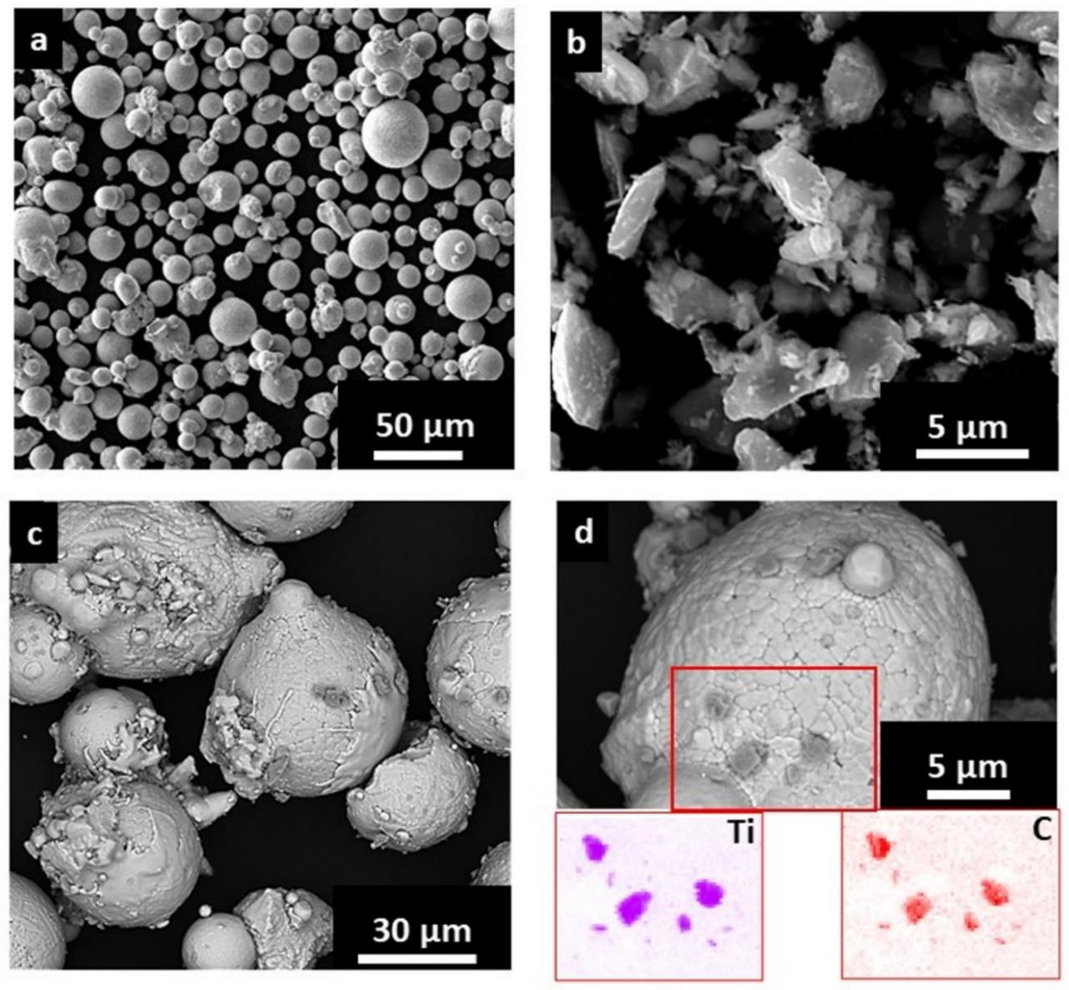
Gas atomized powders of IN625 (dimensions mainly from 10 to 50 µm with a D50 of around 26 µm) were provided by EOS GmbH (Krailling/Munich, Germany) while the TiC particles (mainly from 1 to 5 µm) were purchased from H.C. Starck (Goslar, Germany). The chemical composition of the IN625 alloy (Table 1) was evaluated by scanning electron microscope (SEM, Phenom XL, Phenom-World BV, Eindhoven, The Netherlands) equipped with an energy dispersive spectroscopy (EDS) system, while the concentration of the carbon was evaluated using combustion analysis (CS 744 LECO—analyzer, Leco, St. Joseph, MI, USA). The chemical composition of the powder batch was compatible with the chemical composition range given in the UNS N06625.
The IN625 and TiC powders were mixed in a ceramic jar in a ball milling system with the application of a speed rate of 60 rpm for 48 h (without any grinding medium). Moreover, the mixed powder was sieved below 50 µm before placing it into the LPBF machine.
For the LPBF process, the powder should be characterized by good flowability in order to spread a homogenous layer of loose powder on the building platform. In contrast, a non-homogenous layer of powder can cause defects inside the parts [27,28].
The addition of irregular TiC particles can affect the flowability of the powder, and therefore, the flowability of mixed IN625/TiC powder with different percentages of TiC particles was compared to that of IN625 alloy. The flowability was determined using the Carney flowmeter funnel based on the ASTM B964. It should be noted that this test was performed because the powder did not flow in the Hall flowmeter funnel.
The trend showed a decrement of flowability due to the addition of TiC particles. Moreover, the test could not be performed after adding 2 wt.% of TiC particles, as reported in Table 2. Therefore, it was considered to be IN625/TiC composite with 1 wt.% of TiC, which still flows in the Carney funnel.
The SEM analysis revealed that the particles of the gas atomized IN625 powder were fairly spherical with some irregular and satellite particles (Figure 1a). In contrast, the TiC particles presented irregular shapes with a dimension mainly from 1 to 5 µm (Figure 1b). The SEM images of the mixed powder (99 wt.% IN625 and 1 wt.% TiC) are displayed in Figure 1c,d. It is possible to observe that the TiC reinforcement covers the IN625 particles, as better highlighted in the EDS maps in Figure 1d.
2.2. Material Processing Methods
A MLab Cusing R machine (Concept Laser GmbH, Lichtenfels, Germany) equipped with a fiber laser with a power up to 100 W and a laser spot of approximately 50 µm was employed in the current investigation. Cubes (10 mm × 10 mm × 10 mm) made of IN625 and IN625/TiC were processed using a laser power of 95 W combined with a hatching distance of 0.04 mm, a layer thickness of 20 µm, and a scanning speed of 600 mm/s. A scanning strategy involving stripes of 5 mm with an angle rotation of 67° for consecutive layers was used.
These parameters and scanning strategy allowed us to produce IN625/TiC and IN625 samples with a relative density superior to 99.8%, determined by optical analysis on the polished samples.
A part of the samples was then solution annealed at 1150 °C for 2 h, followed by water quenching. This is one of the standard heat treatments performed on IN625 alloy to solubilize the material, triggering recrystallization and grain growth [29,30]. The as-built and solution-annealed conditions of the two materials will be hereafter abbreviated as AB and SOL, respectively.
2.3. Microstructure and Hardness Investigations
The AB and SOL samples of IN625 and IN625/TiC were cut along the building direction and then grounded with progressive finer SiC abrasive papers and then polished with diamond suspensions (3 and 1 µm) and a final polishing step with alumina suspension (0.3 µm) was undertaken. The samples were etched using a solution of hydrochloric acid and nitric acid (3:1).
The microstructure was evaluated by a light optical microscope (LOM, Leica DMI5000M, Wetzlar, Germany), SEM (Phenom XL, Phenom-World BV, Eindhoven, The Netherlands) and a focused ion beam scanning electron microscope (FIB-SEM, TESCAN S9000G, Tescan Company, Brno, Czech Republic) equipped with an EDS system. Moreover, the texture and grain sizes of the as-built and solution-annealed IN625 and IN625/TiC samples were examined by means of FIB-SEM equipped with an electron backscatter diffraction (EBSD) analyzer. The specimens were tilted by 70° and scanned at 20 kV and 10 nA, with a 2–3 µm step, analyzing the samples along the building direction (z-axis). It should be noted that the EBSD analysis was performed on samples polished down to 0.05 µm using alumina suspension. In order to further investigate the formation of the phases, XRD analyses were also performed using an X-Pert Philips diffractometer (PANalytical, Almelo, The Netherlands) by CuKα radiation in a Bragg Brentano configuration working at 40 kV and 40 mA with a step size of 0.013° and counting at each step for 25 s, from 30 to 65°.
Finally, the hardness was tested by means of Brinell hardness measurements HBW2.5/62.5 using an EMCO TEST M4U durometer (EMCO-TEST Prüfmaschinen GmbH, Kuchl, Austria), according to the ASTM E10 standard. The test was performed on three samples for each condition, performing five indentations per sample along the building direction.
3. Results and Discussion
3.1. Grain Structures Evolution under Solution Annealing
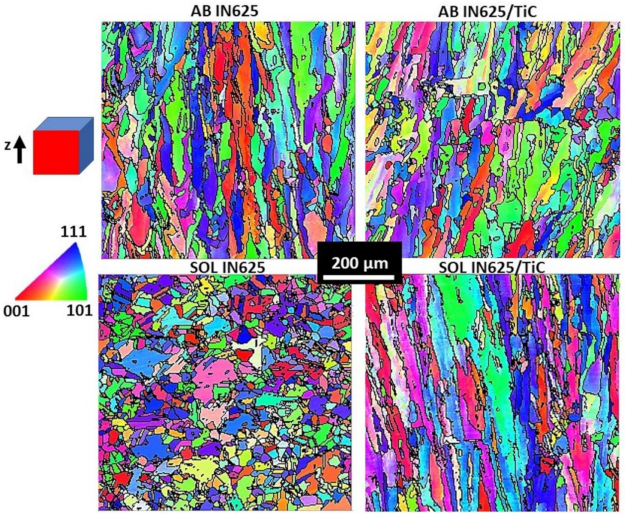
EBSD maps of the AB and SOL conditions of the IN625 and IN625/TiC samples along the building direction are reported in Figure 2.
The AB IN625 and AB IN625/TiC microstructure mainly consisted of columnar grains with lengths up to around 250–350 µm and width around 10–50 µm, coupled to a minor fraction of small grains. The columnar grains derived from the heat flux dissipation from the top of the melt pool down to the building platform, creating an anisotropic microstructure.
The addition of micro-TiC particles may help to refine the grain structures, even though the addition of 1 wt.% may result in a limited grain refinement mechanism, also taking into account the fact that the maximum length of the columnar grains resulted in similarity to the AB IN625 condition.
After the solution annealing treatment, the IN625 presented equiaxed grains with dimensions ranging from 5 to around 90 µm, due to recrystallization. On the other hand, the IN625/TiC still preserved the columnar grain structures, indicating that an elevated temperature is necessary to induce the recrystallization with respect to the IN625 alloy. For the composite, the columnar grains became slightly bigger, with lengths up to around 400 µm and width up to approximately 80 µm compared to the AB IN625/TiC, suggesting a slight grain coarsening due to the high temperature of the solution annealing treatment.
It should be noted that the grain sizes of the two materials were homogenous in the different areas observed along the z-axis.
The relatively weak <001> texture of the AB condition can be attributed to different parameters. For LPBF Ni-based superalloys, it is reported that the process parameters such as the laser power, scanning speed, hatching distance coupled to the scanning strategy have a crucial role in developing the crystallographic texture. This derives from the change of the energy delivered to the material, thus influencing its thermal history, such as heat flow direction, cooling rate, and temperature gradient [31,32,33,34,35].
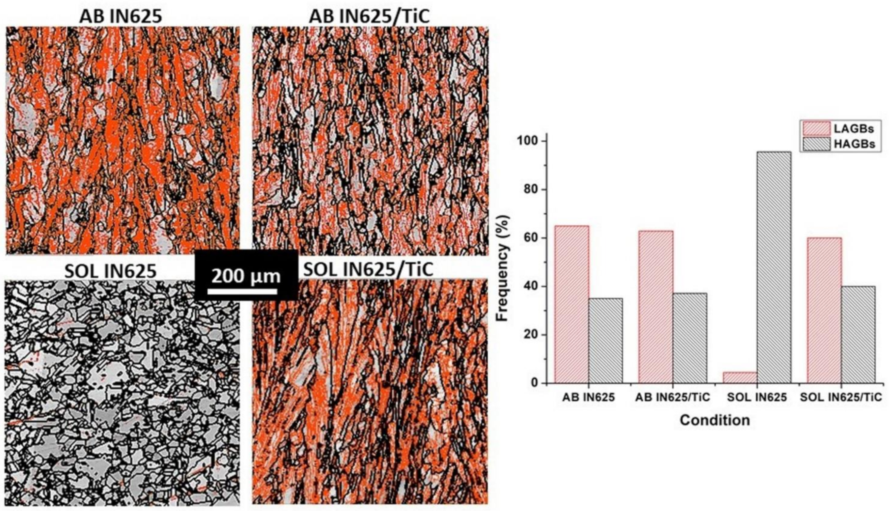
The fraction of low angle grain boundaries (LAGBs ϴ ≤ 10°) and high angle grain boundaries (HAGBs ϴ > 10°) were estimated by EBSD analysis, as reported in Figure 3. The IN625 and IN625/TiC presented a similar quantity of LAGBs (around 65–63%) and HAGBs (about 35–37%). After the solution annealing treatment, the complete recrystallization and grain growth of the IN625 material developed a frequency of HAGBs of 95.6%, thus almost eliminating all the LAGBs. On the other hand, the IN625/TiC composites only exhibited a slight increment of HAGBs, with a frequency of 40%, coupled to a limited reduction of LAGBs, reaching a frequency of 60%. Therefore, it is evident that the TiC particles provided a significant obstacle to altering the grain structures. In another study, it was reported that the use of TiC particles with 40 nm had the effect of increasing the LAGBs with respect to the alloy in the AB state [25]. This was caused by the high number of subgrain structures induced by the nano-TiC particles. On the contrary, in this work, considering the micro-TiC size, no significant impact seems visible in the AB condition. Only after applying the solution annealing treatment, the key role of the micro-TiC reinforcement in maintaining the original grain structures was highlighted.
3.2. Microstructure and Phases Evolution
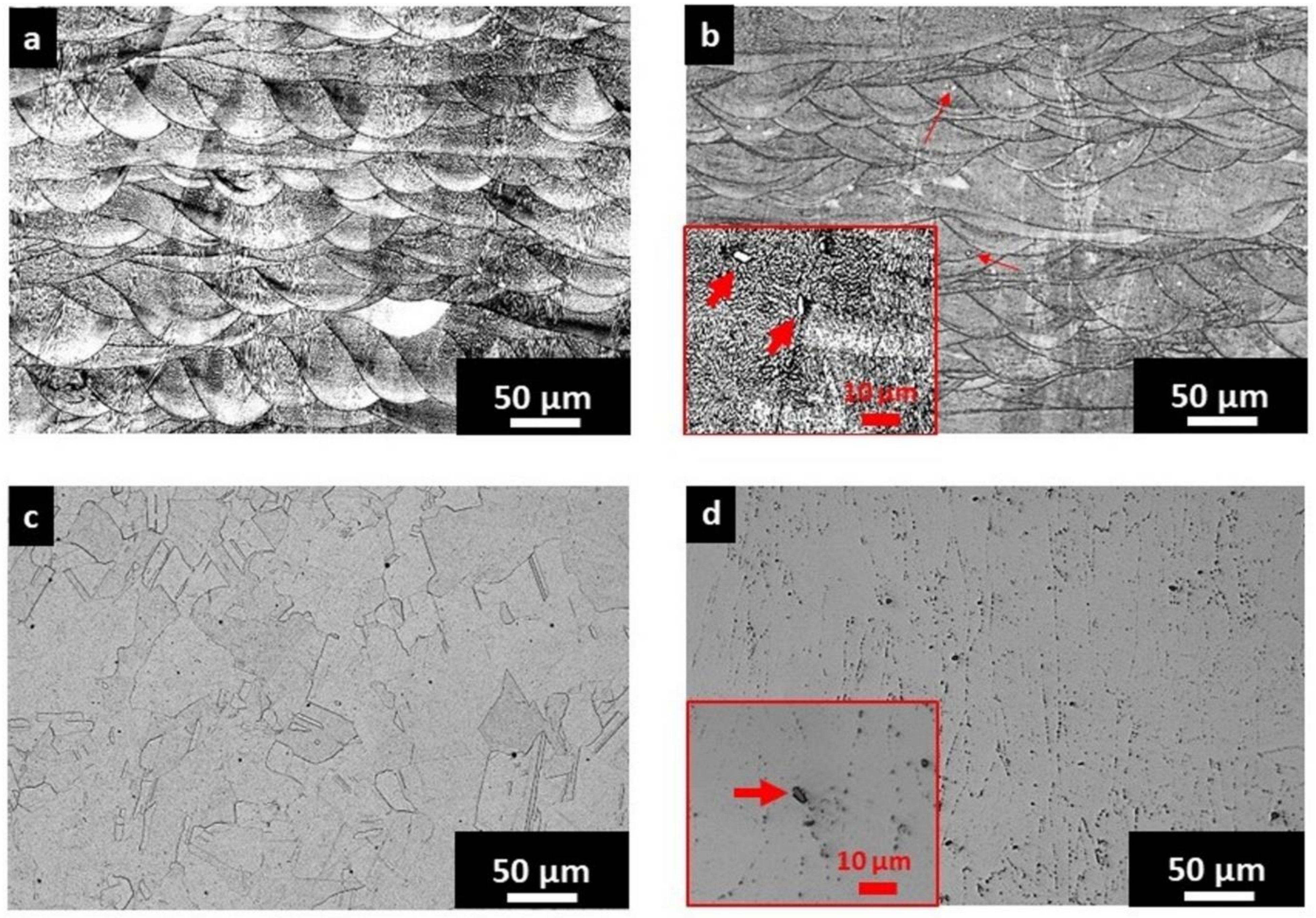
The microstructure of the AB IN625 samples (Figure 4a) shows the melt pool contours as well as the narrow dendritic structures. For the IN625/TiC, the TiC particles were dispersed into the material both inside and along the melt pool contours, as highlighted by the red arrows in Figure 4b and in the insert. The TiC particles resulted in being homogenously dispersed throughout the composite without showing particular enriched zones. Analyzing the LOM images, it is possible to evaluate that the dimensions of the TiC particles are in the range from 1 to 5 µm, suggesting that only a partial dissolution could occur during the melting. This is in agreement with another work that reported that the high melting temperature of the TiC particles (≈3167 °C [12]) hinders the complete melting of the particles [36].
After the solution annealing, the IN625 material showed equiaxed grains and twin grain boundaries due to the recrystallization and grain growth occurring at high temperatures. The LOM image of the SOL IN625 (Figure 4c) reveals the meager fraction of formed carbides in the alloy. On the contrary, the SOL IN625/TiC samples exhibited columnar grains with intergranular and intragranular carbides. Moreover, TiC particles could still be detectable in the insert in Figure 4d. In this case, the high number of LAGBs could act as sites for the formation of the carbides. At the same time, the partial dissolution of TiC carbides may have provided carbon to the matrix, promoting the formation of carbides. These microstructure features indicated that the addition of TiC particles affects the grain structures as well as the concentration of the formed phases.
It should be noted that considering the literature and the time-temperature-transformation (TTT) diagram of the IN625 alloy, the thermal exposures at 1150 °C can promote the formation of carbides, more specifically MC carbides [17,18,37,38]. Further LOM images of the polished AB and SOL IN625/TiC samples are provided in Figure A1 (Appendix A) in order to highlight the distribution and morphology of the TiC particles.
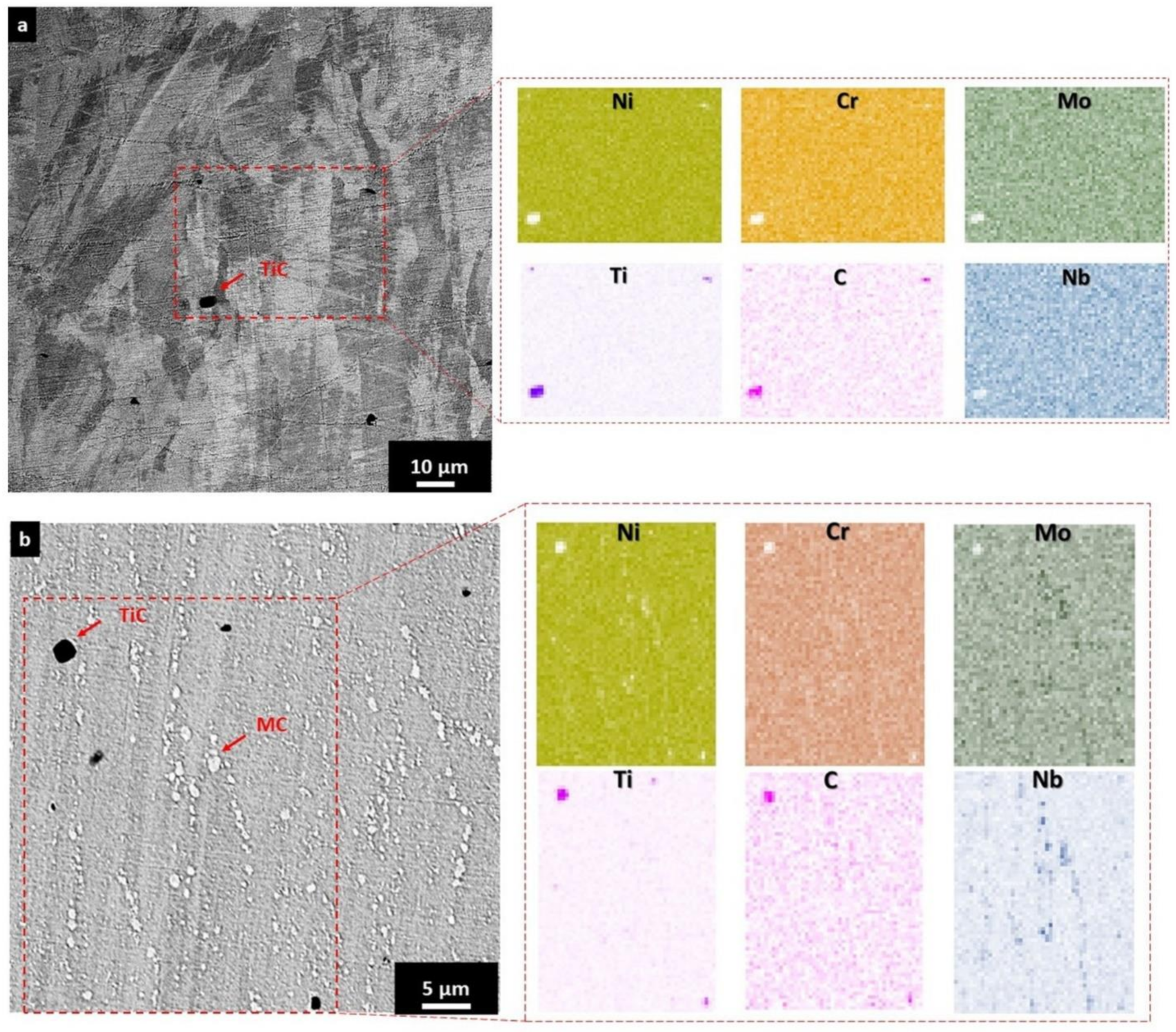
For the AB IN625/TiC state, EDS analysis confirmed that the added micro-TiC particles were inside the grains, along the grain boundaries and the melt pool contours. This can be observed by the EDS analysis revealing the enrichment of Ti and C together with the depletion of Ni, Cr, Nb, and Mo (Figure 5a).
After the solution annealing treatment, it was possible to observe micro-TiC particles as well as the bright phases associated with the formed MC carbides with dimensions up to around 2.0 µm, as highlighted by the red arrows and EDS maps in Figure 5b.
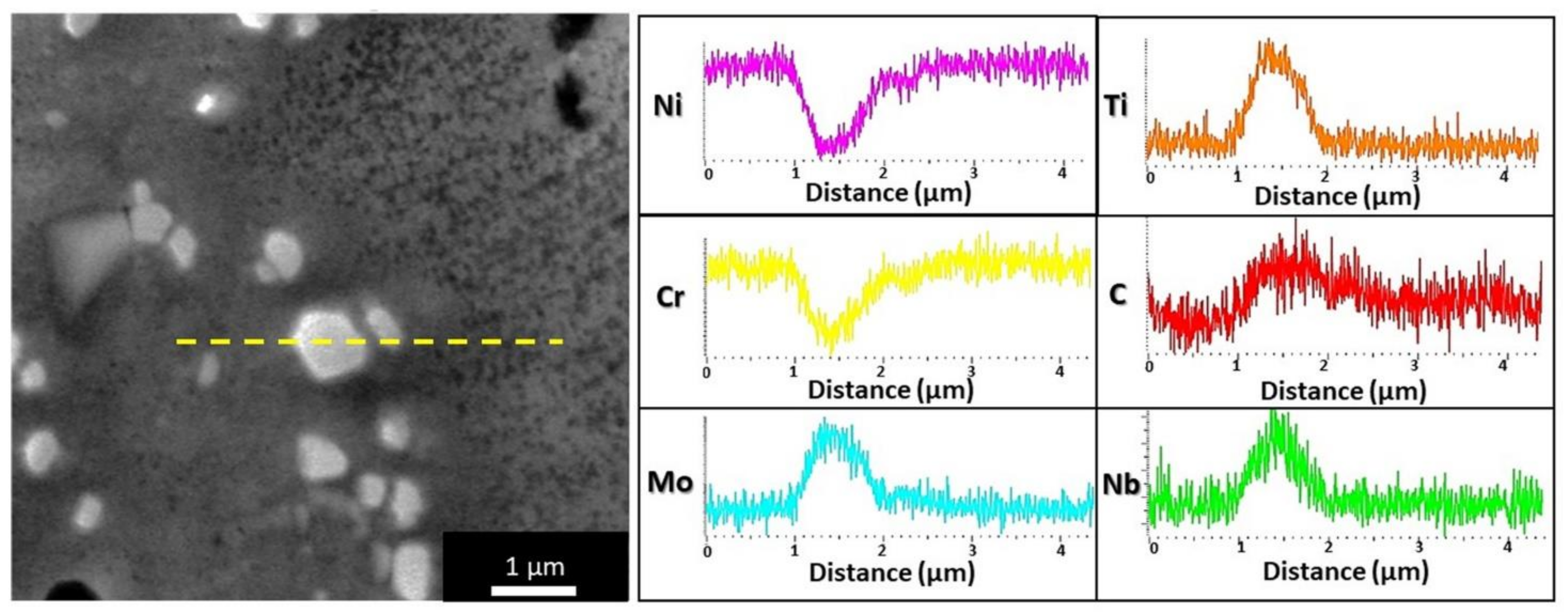
In order to further analyze the formed MC carbides, an EDS scan line at higher magnification was performed (Figure 6). In this way, it was possible to detect a higher concentration of Nb, Mo, Ti, and C correlated with the depletion of Ni and Cr with respect to the gamma austenitic matrix, thus lending support to the formation of MC carbides [38,39,40]. As mentioned before, the formation of MC carbides is compatible with the thermal exposures at 1150 °C [17,38].
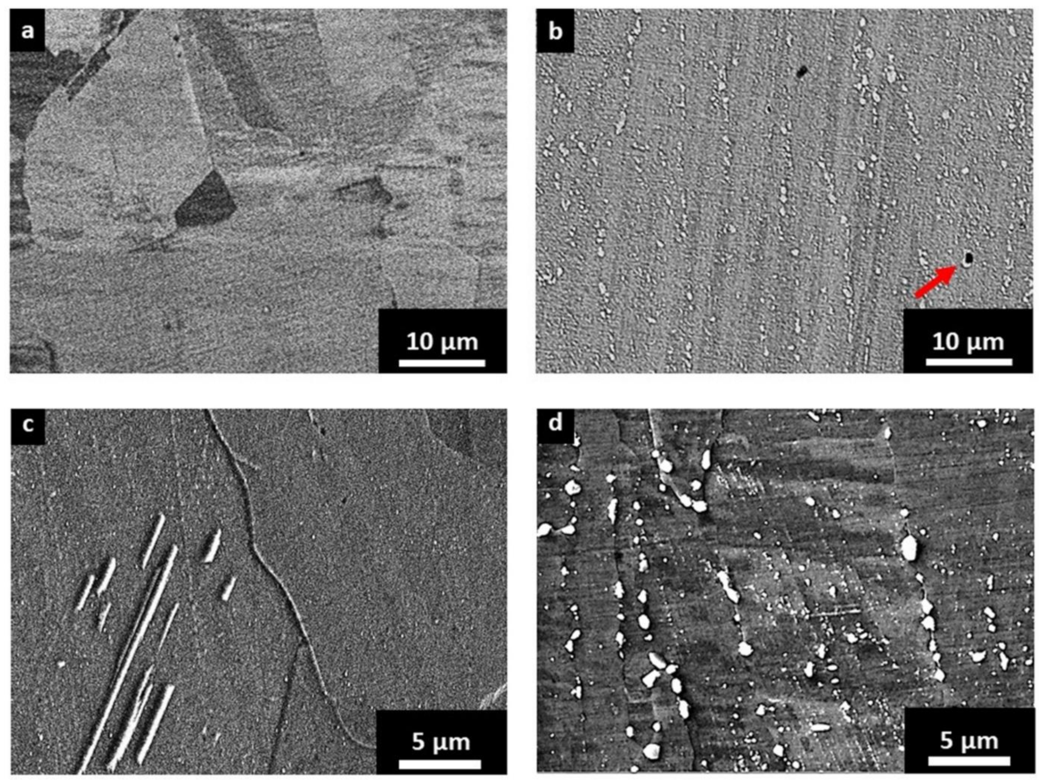
It is possible to compare the different concentrations of carbides of the SOL IN625 (Figure 7a,c) and SOL IN625/TiC (Figure 7b,d). The SOL IN625 state presented the complete dissolution of the fine dendritic structures as well as a limited quantity of carbides. On the contrary, for the SOL IN625/TiC, the LAGBs areas seemed to act as the site for the formation of the carbide during thermal exposures. This resulted in a more pronounced formation of MC carbides compared to the base alloy (Figure 7b,d). Moreover, it is interesting to observe by microstructure investigation that the TiC particles could act as an area for the formation of MC carbides, as indicated by red arrow in Figure 7b.
This brings up interesting considerations about the possible application of this composite material. When IN625 is subjected to intermediate temperatures, Cr-rich M23C6 carbides tend to appear inside the alloy. This phase consumes Cr, reducing the matrix corrosion resistance. However, a heat treatment that acts to form MC carbides can be performed to limit the carbon available in the alloy for the formation of M23C6 carbides [41]. In this particular case, the formation of MC carbides may help to prevent the formation of M23C6 carbides, thus avoiding intergranular corrosion under intermediate temperatures. Moreover, the high quantity of carbides can help to increase the hardness of the material.
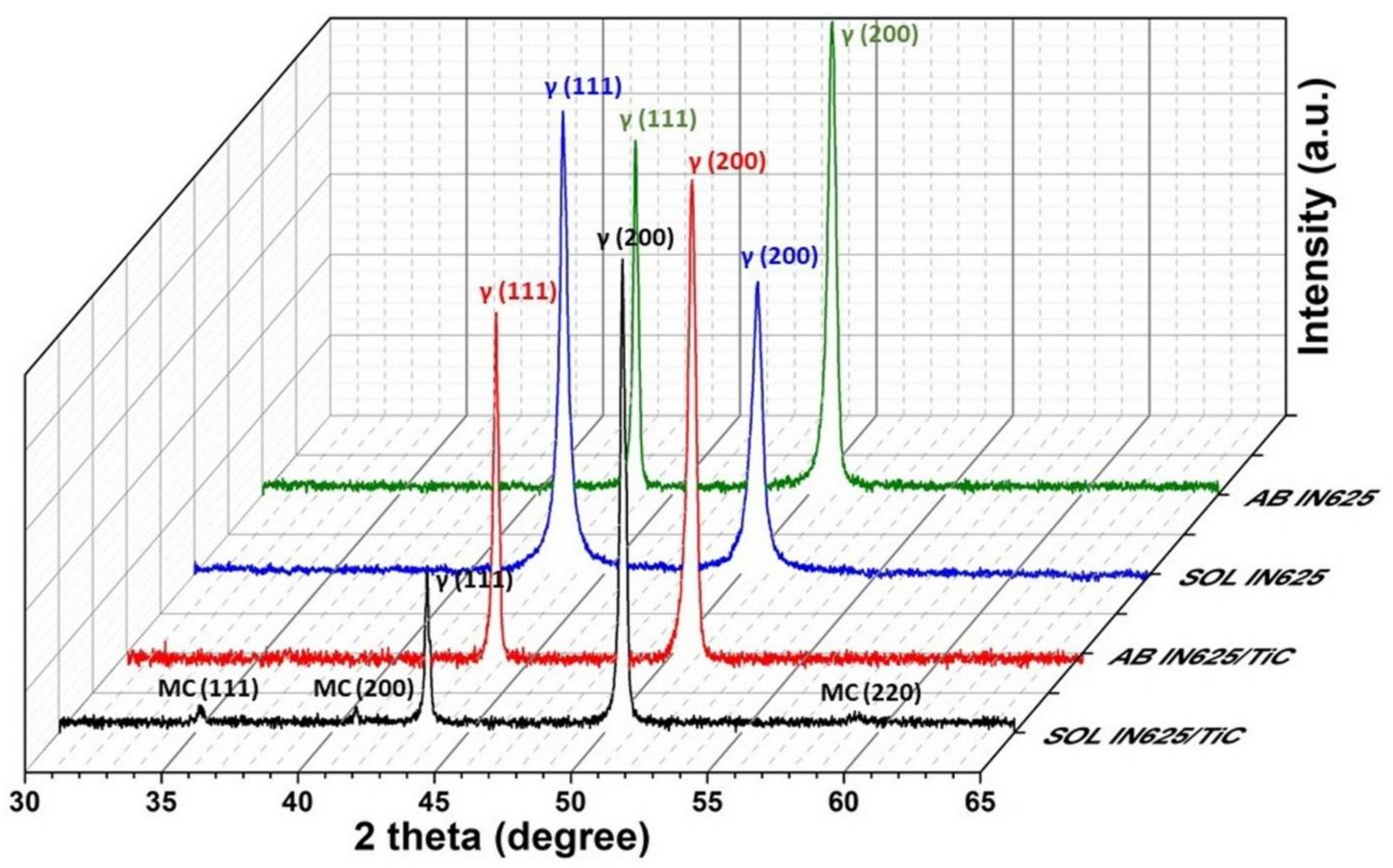
Figure 8 compares the XRD patterns of the IN625 and IN625/TiC samples in the AB and SOL conditions. The AB and SOL IN625 states were characterized by the peaks of the gamma austenitic matrix (γ phase). No other peaks associated with different phases could be detected by XRD analysis. Likewise, the AB IN625/TiC presented only the peaks correlated with the γ phase. Only after the solution annealing at high temperature, the SOL IN625/TiC state exhibited peaks attributed to the formation of the MC carbides. Using the peaks of the MC carbides, it was possible to estimate a lattice parameter of 0.441 nm, which is in line with the reported lattice parameters of the MC carbides (between 0.430 and 0.470 nm) [30]. These results are supported by the SEM analysis, revealing that SOL IN625/TiC exhibited a higher concentration of carbides than the SOL IN625 alloy, thus allowing them to be detected by XRD analysis.
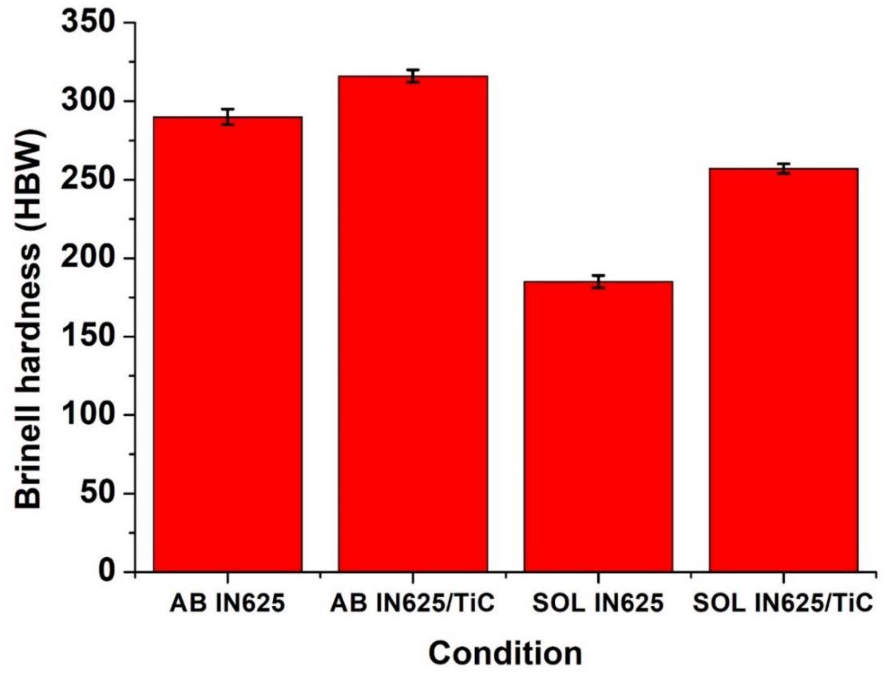
3.3. Hardness Evolution
Figure 9 reports the trend of the Brinell hardness for the alloy and composite built using the same process parameters. In the AB condition, the composite presented slightly higher hardness than the alloy. This can be correlated with the addition of the hardening TiC particles.
For the IN625, the solution annealing promoted softening due to the reduction of dislocation density and the elimination of the dendritic structures coupled to the hardening process due to the formation of smaller grains. The combination of the two mechanisms led to a drastic hardness reduction. On the other hand, the composite tended to retain its hardness, showing a minor decline. This can be correlated to the reduced grain coarsening, which tends to decrease the hardness, coupled to the formation of carbides, provoking a hardening mechanism. From the results, it is therefore evident that the composite presented higher microstructure stability under high thermal exposures.
4. Conclusions
The study highlights the superior microstructure stability of the composite with respect to the alloy, revealing that higher microstructure stability and hardness can be developed with the addition of only 1 wt.% of micro-TiC particles inside the IN625 alloy.
The AB IN625 and IN625/TiC materials were characterized by the predominant formation of columnar grains along the building direction. After solution annealing at high temperature, the IN625/TiC did not show signs of evident recrystallization, preserving the columnar grains along the building direction. On the other hand, the alloy showed complete recrystallization after the same thermal exposure.
The SOL IN625/TiC composite presented a fraction of LAGBs slightly inferior to the AB IN625/TiC condition. On the contrary, the SOL IN625 exhibited almost the absence of LAGBs, drastically inferior to the AB IN625 with over 60% of LAGBs. The high degree of LAGBs of the SOL IN625/TiC appeared to be responsible for the marked formation of carbides since the LAGBs act as sites for their precipitation. Moreover, partial dissolution of TiC particles could favor the carbide formation due to the increment of carbon into the austenitic matrix. The limited grains modification and the formation of a higher concentration of carbides resulted in greater hardness for the SOL IN625/TiC compared to the SOL IN625 alloy.
Similar results could be useful for the development of new composites by LPBF in order to enhance specific properties as well as high microstructure stability under more intense temperatures than the base alloys.
Author Contributions
Conceptualization, G.M.; methodology, G.M. and A.A.; investigation, G.M., A.A., E.B.; data curation, G.M., E.B.; writing—original draft preparation, G.M.; writing—review and editing, G.M., A.A. and E.B. All authors have read and agreed to the published version of the manuscript.
Funding
This research received no external funding.
Data Availability Statement
The data presented in this study are available on request from the corresponding author.
Acknowledgments
The authors would like to thank Francesco Viola and Daniele Nigro for the support in the metallographic preparation during this research. Moreover, the authors would like to acknowledge the Integrated Additive Manufacturing Centre at Politecnico di Torino (IAM@PoliTo), where the specimens were produced.
Conflicts of Interest
The authors declare no conflict of interest.
Appendix A
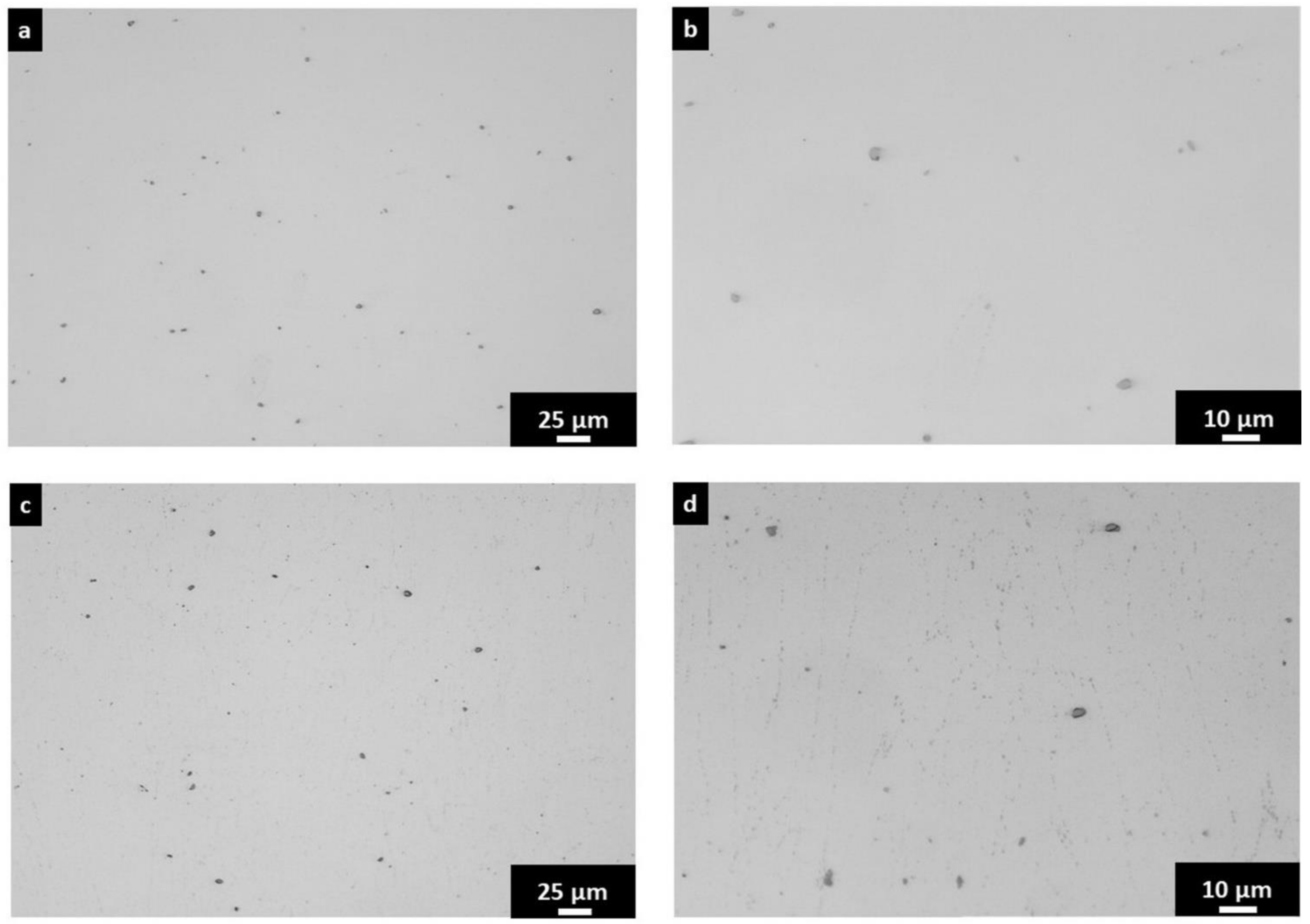
The polished LOM images of the AB IN625/TiC (Figure A1a,b) and the SOL IN625/TiC samples (Figure A1c,d) show the distribution and morphology of the TiC particles. After polishing, it should be noted that the SOL IN625/TiC also starts to reveal the carbides formed during the heat treatment mainly located along the grain boundaries.
Figure A1.
LOM images at different magnifications of the polished (a,b) AB IN625/TiC and (c,d) SOL IN625/TiC samples along the building direction.
Figure A1.
LOM images at different magnifications of the polished (a,b) AB IN625/TiC and (c,d) SOL IN625/TiC samples along the building direction.

References
- Gu, D.D.; Meiners, W.; Wissenbach, K.; Poprawe, R. Laser additive manufacturing of metallic components: Materials, processes and mechanisms. Int. Mater. Rev. 2012, 57, 133–164. [Google Scholar] [CrossRef]
- Herzog, D.; Seyda, V.; Wycisk, E.; Emmelmann, C. Additive manufacturing of metals. Acta Mater. 2016, 117, 371–392. [Google Scholar] [CrossRef]
- Marchese, G.; Aversa, A.; Lorusso, M.; Manfredi, D.; Calignano, F.; Lombardi, M.; Biamino, S.; Pavese, M. Development and characterisation of aluminium matrix nanocomposites ALSi10Mg/MgAl2O4 by laser powder bed fusion. Metals 2018, 8, 175. [Google Scholar] [CrossRef] [Green Version]
- Xi, L.X.; Zhang, H.; Wang, P.; Li, H.C.; Prashanth, K.G.; Lin, K.J.; Kaban, I.; Gu, D.D. Comparative investigation of microstructure, mechanical properties and strengthening mechanisms of Al-12Si/TiB2 fabricated by selective laser melting and hot pressing. Ceram. Int. 2018, 44, 17635–17642. [Google Scholar] [CrossRef]
- Li, X.W.; Shi, S.; Han, S.; Hu, X.G.; Zhu, Q.; Lu, H.X.; Li, W.W.; Shi, Y.S.; Ding, H. Microstructure, solidification behavior and mechanical properties of Al-Si-Mg-Ti/TiC fabricated by selective laser melting. Addit. Manuf. 2020, 34. [Google Scholar] [CrossRef]
- Liu, Y.; Tang, M.; Hu, Q.; Zhang, Y.; Zhang, L. Densification behavior, microstructural evolution, and mechanical properties of TiC/AISI420 stainless steel composites fabricated by selective laser melting. Mater. Des. 2020, 187, 1–13. [Google Scholar] [CrossRef]
- Chen, L.; Sun, Y.; Li, L.; Ren, X. Microstructure evolution, mechanical properties, and strengthening mechanism of TiC reinforced Inconel 625 nanocomposites fabricated by selective laser melting. Mater. Sci. Eng. A 2020, 792, 139655. [Google Scholar] [CrossRef]
- Cao, S.; Gu, D.; Shi, Q. Relation of microstructure, microhardness and underlying thermodynamics in molten pools of laser melting deposition processed TiC/Inconel 625 composites. J. Alloys Compd. 2017, 692, 758–769. [Google Scholar] [CrossRef]
- Shi, Q.; Gu, D.; Xia, M.; Cao, S.; Rong, T. Effects of laser processing parameters on thermal behavior and melting/solidification mechanism during selective laser melting of TiC/Inconel 718 composites. Opt. Laser Technol. 2016, 84, 9–22. [Google Scholar] [CrossRef]
- Zhang, B.; Bi, G.; Nai, S.; Sun, C.N.; Wei, J. Microhardness and microstructure evolution of TiB2 reinforced Inconel 625/TiB2 composite produced by selective laser melting. Opt. Laser Technol. 2016, 80, 186–195. [Google Scholar] [CrossRef]
- Aversa, A.; Marchese, G.; Lorusso, M.; Calignano, F.; Biamino, S.; Ambrosio, E.P.; Manfredi, D.; Fino, P.; Lombardi, M.; Pavese, M. Microstructural and Mechanical Characterization of Aluminum Matrix Composites Produced by Laser Powder Bed Fusion. Adv. Eng. Mater. 2017, 19, 1–11. [Google Scholar] [CrossRef]
- Cooper, D.E.; Blundell, N.; Maggs, S.; Gibbons, G.J. Additive layer manufacture of Inconel 625 metal matrix composites, reinforcement material evaluation. J. Mater. Process. Technol. 2013, 213, 2191–2200. [Google Scholar] [CrossRef]
- Carter, L.N.; Wang, X.; Read, N.; Khan, R.; Aristizabal, M.; Essa, K.; Attallah, M.M. Process optimisation of selective laser melting using energy density model for nickel based superalloys. Mater. Sci. Technol. 2016, 32, 657–661. [Google Scholar] [CrossRef]
- Li, S.; Wei, Q.; Shi, Y.; Zhu, Z.; Zhang, D. Microstructure Characteristics of Inconel 625 Superalloy Manufactured by Selective Laser Melting. J. Mater. Sci. Technol. 2015, 31, 946–952. [Google Scholar] [CrossRef]
- Koutiri, I.; Pessard, E.; Peyre, P.; Amlou, O.; de Terris, T. Influence of SLM process parameters on the surface finish, porosity rate and fatigue behavior of as-built Inconel 625 parts. J. Mater. Process. Technol. 2018, 255, 536–546. [Google Scholar] [CrossRef]
- Marchese, G.; Bassini, E.; Calandri, M.; Ambrosio, E.P.; Calignano, F.; Lorusso, M.; Manfredi, D.; Pavese, M.; Biamino, S.; Fino, P. Microstructural investigation of as-fabricated and heat-treated Inconel 625 and Inconel 718 fabricated by direct metal laser sintering: Contribution of Politecnico di Torino and Istituto Italiano di Tecnologia ( IIT ) di Torino. Met. Powder Rep. 2016, 71, 273–278. [Google Scholar] [CrossRef]
- Floreen, S.; Fuchs, G.E.; Yang, W.J. The Metallurgy of Alloy 625. In Superalloys 718, 625, 706 and Various Derivatives; Loria, E.A., Ed.; The Minerals, Metals & Materials Society: Pittsburgh, PA, USA, 1994; pp. 13–37. [Google Scholar]
- Shoemaker, L.E. Alloys 625 and 725: Trends in properties and applications. In Superalloys 718, 625, 706 and Derivatives; Loria, E.A., Ed.; The Minerals, Metals & Materials Society: Pittsburgh, PA, USA, 2005; pp. 409–418. [Google Scholar]
- Smith, G.D.; Tillack, D.J.; Patel, S.J. Alloy 625–Impressive Past/Significant Presence/Awesome Future. In Superalloys 718, 625, 706 and Various Derivatives; Loria, E.A., Ed.; The Minerals, Metals & Materials Society: Pittsburgh, PA, USA, 2001; pp. 35–46. [Google Scholar]
- Hack, H.; Link, R.; Knudsen, E.; Baker, B.; Olig, S. Mechanical properties of additive manufactured nickel alloy 625. Addit. Manuf. 2017, 14, 105–115. [Google Scholar] [CrossRef]
- Kreitcberg, A.; Brailovski, V.; Turenne, S. Effect of heat treatment and hot isostatic pressing on the microstructure and mechanical properties of Inconel 625 alloy processed by laser powder bed fusion. Mater. Sci. Eng. A 2017, 689, 1–10. [Google Scholar] [CrossRef]
- Inaekyan, K.; Kreitcberg, A.; Turenne, S.; Brailovski, V. Microstructure and mechanical properties of laser powder bed-fused IN625 alloy. Mater. Sci. Eng. A 2019, 768, 138481. [Google Scholar] [CrossRef]
- Kreitcberg, A.; Brailovski, V.; Turenne, S. Elevated temperature mechanical behavior of IN625 alloy processed by laser powder-bed fusion. Mater. Sci. Eng. A 2017, 700, 540–553. [Google Scholar] [CrossRef]
- Rong, T.; Gu, D.; Shi, Q.; Cao, S.; Xia, M. Effects of tailored gradient interface on wear properties of WC/Inconel 718 composites using selective laser melting. Surf. Coat. Technol. 2016, 307, 418–427. [Google Scholar] [CrossRef]
- Chen, L.; Sun, Y.; Li, L.; Ren, X. Effect of heat treatment on the microstructure and high temperature oxidation behavior of TiC/Inconel 625 nanocomposites fabricated by selective laser melting. Corros. Sci. 2020, 169, 108606. [Google Scholar] [CrossRef]
- Wang, P.; Zhang, B.; Tan, C.C.; Raghavan, S.; Lim, Y.F.; Sun, C.N.; Wei, J.; Chi, D. Microstructural characteristics and mechanical properties of carbon nanotube reinforced Inconel 625 parts fabricated by selective laser melting. Mater. Des. 2016, 112, 290–299. [Google Scholar] [CrossRef]
- DebRoy, T.; Wei, H.L.; Zuback, J.S.; Mukherjee, T.; Elmer, J.W.; Milewski, J.O.; Beese, A.M.; Wilson-Heid, A.; De, A.; Zhang, W. Additive manufacturing of metallic components–Process, structure and properties. Prog. Mater. Sci. 2018, 92, 112–224. [Google Scholar] [CrossRef]
- Sames, W.J.; List, F.A.; Pannala, S.; Dehoff, R.R.; Babu, S.S. The metallurgy and processing science of metal additive manufacturing. Int. Mater. Rev. 2016, 61, 315–360. [Google Scholar] [CrossRef]
- Chandler, H. Heat Treater’s Guide: Practices and Procedures for Nonferrous Alloys; ASM International: Materials Park, OH, USA, 1996; ISBN 0871705656. [Google Scholar]
- Donachie, M.J.; Donachie, S.J. Superalloys: A Technical Guide, 2nd ed.; ASM International: Materials Park, OH, USA, 2002; ISBN 0871707497. [Google Scholar]
- Fang, X.Y.; Li, H.Q.; Wang, M.; Li, C.; Guo, Y.B. Characterization of texture and grain boundary character distributions of selective laser melted Inconel 625 alloy. Mater. Charact. 2018, 143, 182–190. [Google Scholar] [CrossRef]
- Carneiro, Í.; Simões, S. Recent advances in ebsd characterization of metals. Metals 2020, 10, 1097. [Google Scholar] [CrossRef]
- Carter, L.N.; Martin, C.; Withers, P.J.; Attallah, M.M. The influence of the laser scan strategy on grain structure and cracking behaviour in SLM powder-bed fabricated nickel superalloy. J. Alloys Compd. 2014, 615, 338–347. [Google Scholar] [CrossRef]
- Popovich, V.A.; Borisov, E.V.; Popovich, A.A.; Sufiiarov, V.S.; Masaylo, D.V.; Alzina, L. Functionally graded Inconel 718 processed by additive manufacturing: Crystallographic texture, anisotropy of microstructure and mechanical properties. Mater. Des. 2017, 114, 441–449. [Google Scholar] [CrossRef]
- Deng, D.; Peng, R.L.; Brodin, H.; Moverare, J. Microstructure and mechanical properties of Inconel 718 produced by selective laser melting: Sample orientation dependence and effects of post heat treatments. Mater. Sci. Eng. A 2018, 713, 294–306. [Google Scholar] [CrossRef]
- Chen, L.; Sun, Y.; Li, L.; Ren, Y.; Ren, X. In situ TiC/Inconel 625 nanocomposites fabricated by selective laser melting: Densification behavior, microstructure evolution, and wear properties. Appl. Surf. Sci. 2020, 518, 145981. [Google Scholar] [CrossRef]
- Ferrer, L.; Pieraggi, B.; Uginet, J.F. Microstructural Evolution During Thermomechanical Processing of Alloy 625. In Superalloys 718, 625 and Various Derivates; Loria, E.A., Ed.; The Minerals, Metals & Materials Society: Pittsburgh, PA, USA, 1991; pp. 217–228. [Google Scholar]
- Vernot-Loier, C.; Cortial, F. Influence of Heat Treatments on Microstructure, Mechanical Properties and Corrosion Behaviour of Alloy 625 Forged Rod. In Superalloys 718, 625 and Various Derivates; Loria, E.A., Ed.; The Minerals, Metals & Materials Society: Pittsburgh, PA, USA, 1991; pp. 409–422. [Google Scholar]
- Cortial, F.; Corrieu, J.M.; Vernot-Loier, C. Influence of heat treatments on microstructure, mechanical properties, and corrosion resistance of weld alloy 625. Metall. Mater. Trans. A 1995, 26, 1273–1286. [Google Scholar] [CrossRef]
- Dutkiewicz, J.; Rogal, Ł.; Kalita, D.; Berent, K.; Antoszewski, B.; Danielewski, H.; St. Węglowski, M.; Łazińska, M.; Durejko, T.; Czujko, T. Microstructure and properties of inconel 625 fabricated using two types of laser metal deposition methods. Materials 2020, 13, 5050. [Google Scholar] [CrossRef] [PubMed]
- Ganesan, P.; Renteria, C.M.; Crum, J.R. Versatile Corrosion Resistance of INCONEL Alloy 625 in Various Aqueous and Chemical Processing Environments. In Superalloys 718, 625 and Various Derivates; Loria, E.A., Ed.; The Minerals, Metals & Materials Society: Pittsburgh, PA, USA, 1991; pp. 663–680. [Google Scholar]
Figure 1.
SEM images of the: (a) IN625 particles, (b) TiC particles, (c) mixed IN625/TiC particles, (d) SEM + EDS maps of an IN625 particle covered by small irregular TiC particles.
Figure 1.
SEM images of the: (a) IN625 particles, (b) TiC particles, (c) mixed IN625/TiC particles, (d) SEM + EDS maps of an IN625 particle covered by small irregular TiC particles.

Figure 2.
EBSD maps of the AB and SOL IN625 and IN625/TiC conditions along the building direction (z-axis). The corresponding inverse pole figure is also included. HAGBs (ϴ > 10°) are pointed out by black lines.
Figure 2.
EBSD maps of the AB and SOL IN625 and IN625/TiC conditions along the building direction (z-axis). The corresponding inverse pole figure is also included. HAGBs (ϴ > 10°) are pointed out by black lines.

Figure 3.
EBSD images of the grain misorientation distributions of the IN625 and IN625/TiC conditions with the chart of the frequency of LAGBs and HAGBs. The HAGBs are marked in black, while the LAGBs are pointed out in red.
Figure 3.
EBSD images of the grain misorientation distributions of the IN625 and IN625/TiC conditions with the chart of the frequency of LAGBs and HAGBs. The HAGBs are marked in black, while the LAGBs are pointed out in red.

Figure 4.
LOM images of: (a) AB IN625; (b) IN625/TiC; (c) SOL IN625; (d) SOL IN625/TiC samples etched along the building direction. The red arrows indicate the TiC particles.
Figure 4.
LOM images of: (a) AB IN625; (b) IN625/TiC; (c) SOL IN625; (d) SOL IN625/TiC samples etched along the building direction. The red arrows indicate the TiC particles.

Figure 5.
EDS maps of the (a) AB IN625/TiC and (b) SOL IN625/TiC states.

Figure 6.
EDS scan line on the bright MC carbides of the SOL IN625/TiC condition.

Figure 7.
SEM images of the (a,c) SOL IN625 and (b,d) SOL IN625/TiC samples revealing the morphology and dimensions of the carbides. The red arrow indicates a TiC particle acting as a site for the formation of MC carbides.
Figure 7.
SEM images of the (a,c) SOL IN625 and (b,d) SOL IN625/TiC samples revealing the morphology and dimensions of the carbides. The red arrow indicates a TiC particle acting as a site for the formation of MC carbides.

Figure 8.
XRD patterns of the AB and SOL IN625 and IN625/TiC samples, revealing the presence of peaks of gamma austenitic phase and MC carbides.
Figure 8.
XRD patterns of the AB and SOL IN625 and IN625/TiC samples, revealing the presence of peaks of gamma austenitic phase and MC carbides.

Figure 9.
Hardness evolution of the AB and SOL IN625 and IN625/TiC conditions.


Table 1.
Chemical composition (in wt.%) evaluated by EDS analysis and combustion analysis (for carbon).
Table 1.
Chemical composition (in wt.%) evaluated by EDS analysis and combustion analysis (for carbon).
| Ni | Cr | Mo | Fe | Nb | Co | Si | Ti | Al | C |
|---|---|---|---|---|---|---|---|---|---|
| 65.8 | 20.5 | 8.1 | 0.7 | 3.9 | 0.1 | 0.3 | 0.3 | 0.3 | 0.012 |
Table 2.
Flowability of the IN625 and IN625/TiC powder determined by the Carney flow test.
| Powder | Carney Flow Time [s/150 g] |
|---|---|
| IN625 | 8.7 ± 0.1 |
| IN625 + 1 wt.% TiC | 14.5 ± 0.5 |
| IN625 + 2 wt.% TiC | - |
| IN625 + 3 wt.% TiC | - |
Publisher’s Note: MDPI stays neutral with regard to jurisdictional claims in published maps and institutional affiliations. |
© 2021 by the authors. Licensee MDPI, Basel, Switzerland. This article is an open access article distributed under the terms and conditions of the Creative Commons Attribution (CC BY) license (https://creativecommons.org/licenses/by/4.0/).
Share and Cite
MDPI and ACS Style
Marchese, G.; Aversa, A.; Bassini, E. Microstructure and Hardness Evolution of Solution Annealed Inconel 625/TiC Composite Processed by Laser Powder Bed Fusion. Metals 2021, 11, 929. https://doi.org/10.3390/met11060929
AMA Style
Marchese G, Aversa A, Bassini E. Microstructure and Hardness Evolution of Solution Annealed Inconel 625/TiC Composite Processed by Laser Powder Bed Fusion. Metals. 2021; 11(6):929. https://doi.org/10.3390/met11060929
Chicago/Turabian StyleMarchese, Giulio, Alberta Aversa, and Emilio Bassini. 2021. "Microstructure and Hardness Evolution of Solution Annealed Inconel 625/TiC Composite Processed by Laser Powder Bed Fusion" Metals 11, no. 6: 929. https://doi.org/10.3390/met11060929
Note that from the first issue of 2016, this journal uses article numbers instead of page numbers. See further details here.