Article

Ballistic Impact Resistance of Bulletproof Vest Inserts Containing Printed Titanium Structures

1
Military Institute of Armament Technology, Prym. S. Wyszynskiego 7 Str., 05-220 Zielonka, Poland
2
Institute of Mechanics and Printing, Faculty of Production Engineering, Warsaw University of Technology, Narbutta 85 Str., 02-524 Warsaw, Poland
3
Łukasiewicz Research Network—Institute of Non-Ferrous Metals, Sowinskiego 5 Str., 44-100 Gliwice, Poland
4
Department of Mechanics, Materials and Biomedical Engineering, Wroclaw University of Science and Technology, Smoluchowskiego 25 Str., 50-370 Wroclaw, Poland
*
Author to whom correspondence should be addressed.
Metals 2021, 11(2), 225; https://doi.org/10.3390/met11020225
Submission received: 28 December 2020 / Revised: 20 January 2021 / Accepted: 22 January 2021 / Published: 28 January 2021

Abstract

:
Finite element modeling of ballistic impact of inserts containing titanium structures were presented in the article. The inserts containing an additional layer made using additive manufacturing technology were analyzed. The layer was created from repetitive elements made without connections (adjacent cells were inseparable). Four variants of printed titanium structures were placed between layers of Twaron CT 750 aramid fabric to create ballistic inserts. In order to assess the ballistic resistance of the inserts, numerical simulations of ballistic impact phenomenon were carried out using LS-Dyna software. In the simulations the inserts were placed on a steel box filled with ballistic clay and were fired at with the 9 × 19 mm full metal jacket (FMJ) Parabellum projectile. The main aim of the work was to check the effectiveness of such solutions in soft ballistic protection applications and to select the most effective variant of 3D printed structure. Results of the numerical analysis showed a high potential for 3D printed structures made of titanium alloys to be used for bulletproof vest inserts. In all analyzed cases the projectile was stopped by the armor. In addition, thanks to the cooperation of adjacent cells, the projectile energy density was distributed over a large area, as evidenced by large volumes of hollows in the ballistic clay. The indentations in the ballistic clay obtained in the simulations were significantly lower than the acceptable value for the back face deformation (BFD) parameter required by international body armor standards.

1. Introduction

The function of a bulletproof vest is to protect the human body from negative effects of an impacting projectile by absorbing and dispersing its kinetic energy. A review of structural and material solutions of ballistic inserts currently used in bulletproof vests shows that layered material systems [1,2,3], such as ceramic [4,5], ceramic-composite [6,7,8,9], titanium [10,11] and polyethylene [12,13] segments, provide effective protection against small caliber ammunition fired from handguns. Such a shield is used to protect the most important internal organs of the human body, which is about 0.5 m2 of the area [14]. Thanks to continuous progress of material engineering [15,16,17] and production technologies, more efficient bulletproof vests may be developed. Current research projects in the field of personal protection [18], are focused on increasing the protected area and reducing areal density of vests related to the v50 ballistic limit.
One of the ways of increasing the protective effectiveness of bulletproof vests may be by using elements made by additive manufacturing technology [19]. Recently, thanks to a wide range of possible additive production methods [20,21], their dynamic development can be observed, especially in medicine [22,23], but also in the defense industry. For example, the stab resistance body armor made of polyamide and carbon fiber plates produced using laser sintered materials technology was analyzed in the paper [24]. The original approach was presented in the paper [25], where a prototype of flexible armor was created on the basis of chitin scales manufactured with the use of 3D printing technology. The armor was composed of segments in the form of scales imitating biological organisms (e.g., crustaceans, fish or chiton). More traditional methods of manufacturing of armor elements were presented in the works [16,26]. In the paper [27], the authors presented a plymetal, which is a new type of composite metal manufactured by a laser-aided additive manufacturing (AM) process using two different metal powders. Ballistic tests were then performed on the structural components made of plymetal with impact velocities of 183–357 m/s. Additive manufacturing technologies were often used to produce porous, honeycomb [28] or cellular structures [29,30,31,32]. An interesting example of ballistic inserts produced by using additive technology was presented in the paper [33]. The inserts were made as an array of many loosely intertwined repetitive elements in the form of closed uniform cells. The cells formed a multi-object layer made of sintered powders in one technological operation. Three-dimensional printing technology is poorly described in cases of impact energy dissipative materials. Most studies refer to materials made of sintered metal powders (aluminum or titanium alloys). The remaining group of materials, for example, aramid or polyethylene, still presents a challenge for 3D printing.
In the article, numerical simulations were performed to check the possibility of using 3D printed titanium structures as energy absorbing and dissipating layers in bullet-proof vests inserts. On the basis of the literature review, it was noted that there is a lack of information regarding the effectiveness of such structures under ballistic impact conditions. Therefore, the phenomenon of the 9 × 19 mm full metal jacket (FMJ) Parabellum projectile impact into a 100 × 100 mm layered composite armor was modelled using LS-Dyna software. The armor included four variants of 3D printed titanium structures placed between layers of Twaron CT 750 aramid fabric. Results of studies were summarized and conclusions were drawn. On the basis of the simulation results an attempt was made to choose the most effective variant of the analyzed structures, as well as to show directions for further works in the field of 3D printing technology in ballistic applications.

2. Materials and Methods

2.1. Materials Insert Configurations

Four variants of 3D printed titanium structures [33] placed between layers of Twaron CT 750 aramid fabric (Figure 1) were analyzed in the study. The structures were made of Ti-6Al-4V titanium alloy with a density of 4.4 g/cm3 and had the form of a grid consisting of many loosely intertwined repeatable components (uniform cells). The whole structure was additively manufactured in one technological operation by sintering powder with laser or electron beam. The grid made in this way may use cells of different geometry (Figure 1). The ratio of empty space between the cells to the total volume of the layer may be within the range of 5–60%. All of the analyzed variants of structures had the same areal density (ms = 18.0 kg/m2) which made it easier to compare their effectiveness.
The analyzed ballistic inserts had dimensions of 100 × 100 mm and a sandwich form (Figure 2). Each variant of titanium structure was placed between layers of Twaron CT 750 aramid fabric (two layers behind and two layers in front of the structure).
Twaron CT 750 is a para-aramid fabric characterized by favorable strength parameters and impact resistance to many types of threats. Laminates made of the fabric are often used in hard body armors. Basic parameters of the fabric are presented in Table 1.

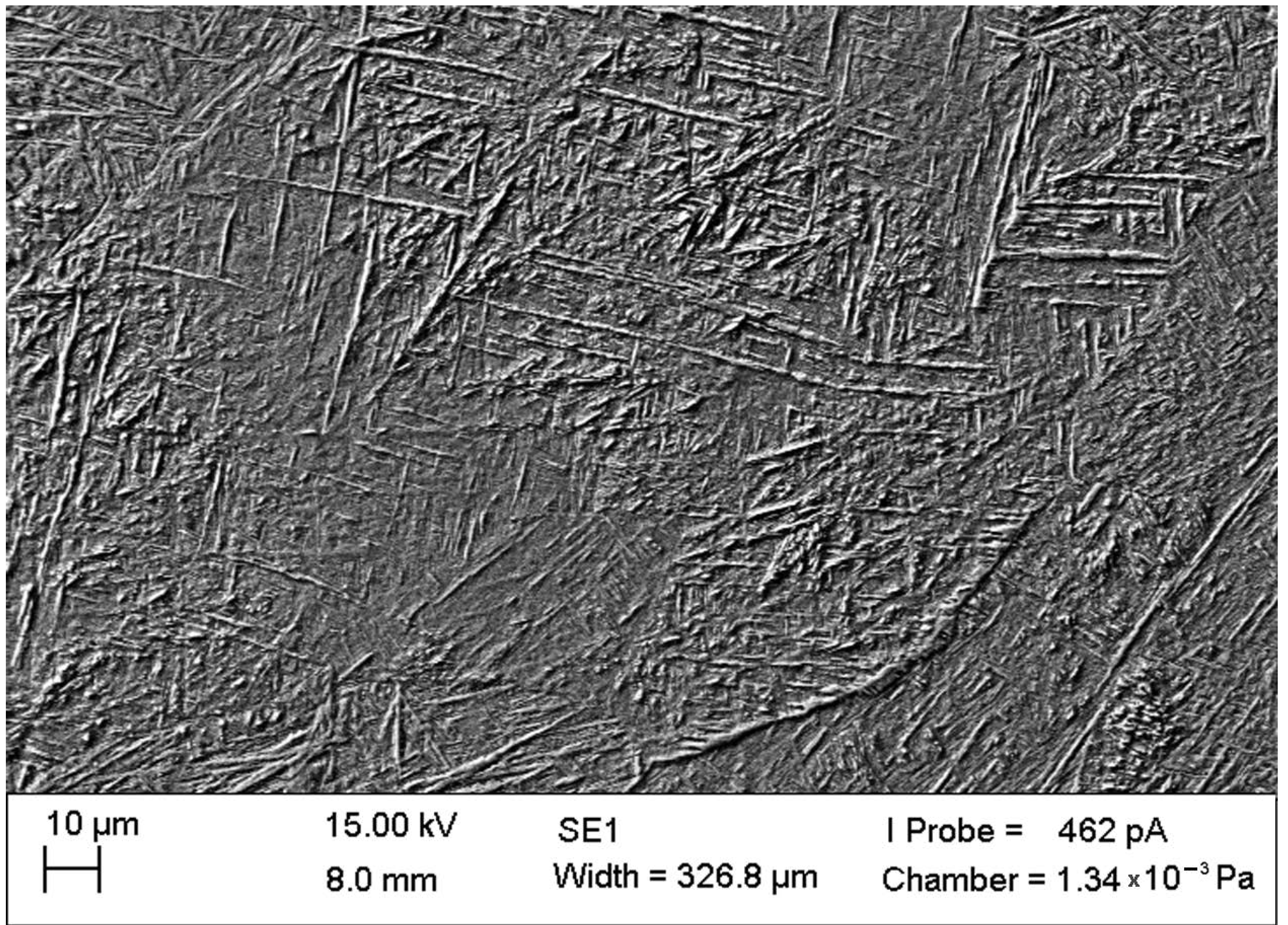
2.2. Construction of the 3D Printed Structures

The 3D printed structures were made by interlacing many cells, through the inner perimeters of the adjacent repetitive elements (Figure 3). That kind of grid has greater strength and energy-dispersing capacities in relation to full structures.
In the analyzed 3D printed structures, adjacent repetitive components had the possibility of angular movement in relation to each other, which allowed modifying of the layer’s geometric dimensions within certain limits. Areal density of structures composed of repetitive elements is smaller than traditional solid composite inserts with similar impact resistance. This feature, together with high flexibility, increases the ergonomics of the user and the protected area of the body [14].
Randomly selected 3D printed components were examined by scanning and light microscopy. Microstructures were analyzed in order to check the influence of the printing process on the quality of generated components. Additive manufacturing using selective laser melting (SLM) technology involves multiple cycles with rapid heating and cooling in the laser melting zone [35]. Such a dynamic heat transfer affects the microstructure of the printed material. The metallographic analysis showed the overall morphology and the effect of the β-phase diffusionless transformation into metastable martensitic α’-phase (Figure 4).
Kinetics of the transformation affected the final phase composition of the alloy, and as a consequence, the final properties of the β alloy [36,37]. As a result, separations of the α’-phase lath martensite were observed on the background of the β-Ti phase. During the metallographic examination a randomly distributed residual porosity was also noticed in the sample (Figure 5).

2.3. 9 mm FMJ Parabellum Projectile

The 9 × 19 mm Parabellum projectile was used in the analyses. The projectile was developed by George Luger in 1902. Since the Second World War it has become one of the most frequently used ammunitions, fired with guns and sub-machine guns. Different variants of the bullet were produced in more than 70 countries around the world. The bullet become standard in NATO countries. In the analyses the full metal jacket (FMJ) version of the projectile was used. The projectile has a rounded shape and consists of a core made of lead/antimony alloy and jacket made of brass or tombac plated steel (Figure 6).
Depending on type, the mass of the projectile can range from 6.8 to 8 g. The projectile can be fired at an initial velocity of 300–420 m/s which gives the kinetic energy of about Ek = 600 J. During the analyses the 9 mm projectile with a mass of 8.0 g, muzzle velocity of 360 m/s and initial energy Ek ~ 518 J was used [38].

2.4. Determination of Material Characteristics for Numerical Modeling

Experimental tests were carried out to gather data necessary for further validation of numerical models of materials used in the simulation. Three types of experiments were performed.
Twaron CT 750 aramid fabric was tested in a quasi-static puncture test of a single layer, 3 layers, 6 layers and 9 layers. The sample was fixed peripherally with a specific cladding pressure moment, and penetrated by impactor moving at a constant speed perpendicular to the target surface. The force acting on the impactor and its displacement were recorded. The obtained material characteristics were used as a reference during the validation process of the fabric numerical model. An example of a single layer of Twaron CT 750 aramid fabric penetration is shown in Figure 7.
In order to check the behavior of the 9 mm FMJ Parabellum projectile at different strain rates and to collect data required for validation of its numerical model, a simple experiment similar to the classic Taylor test described in the literature [39,40,41] was proposed. Ballistic tests of the projectile’s impact into the polished thick non-deformable Armox 500T armor steel plate at appropriate velocities (50–150 m/s achieved by weighing of gunpowder) were carried out. Results of the projectile impact tests and outcomes of the validation tests carried out with the numerical simulations are shown in Figure 8. Deformations of the projectile obtained in simulations and experiments were very similar, which testified that selected values of parameters in material models of projectile components provide proper reproduction of the projectile behavior at the analyzed strain rates.
In the last stage of experimental tests response of ballistic clay to specific loads was determined by performing tests recommended by international standards [42]. GM1 0–0.2 mm ground clay (cyclone) was used. Calibration of the ballistic clay was carried out by simple drop test to confirm a proper plasticity of the material. A cylindrical steel impactor with spherical frontal part, weight of 1 kg and diameter of 44 mm, was dropped from the height of 2 m onto the clay placed in a container (at least three times). The indentation in the clay was measured and compared to the proper value of 25 ± 3 mm.

3. Numerical Investigations

3.1. Assumptions Adopted for Modeling

Phenomenon of ballistic impact of the 9 × 19 mm FMJ Parabellum projectile into layered composite armor consisting of 3D printed titanium structure was modelled with the LS-Dyna software [43,44]. In the model, the ballistic insert was placed on a steel box filled with ballistic clay. The projectile initial velocity was v0 = 360 m/s. Scheme of the analyzed phenomenon is shown in Figure 9.
In order to reduce the time required to complete the calculations, a single symmetry plane was used in the model, thus modelling only half of the system. Due to irregularity of the structures and asymmetry of their interactions with the penetrating projectile, deviation of the projectile from its initial (perpendicular to the target surface) flight path was predicted. Therefore, it was unreasonable to use two symmetry planes which prevent reproducing this effect. Nodes in the plane of symmetry were deprived of possibility of translation and rotation in the appropriate directions. Use of the symmetry plane excluded the possibility of giving the projectile a rotational velocity, which, however, according to the information available in the literature [45], does not significantly affect projectile penetration capability.

3.2. Numerical Models

3.2.1. General Assumptions

Discretization of the simulation components is shown in Figure 10, Figure 11, Figure 12 and Figure 13. It was performed using HyperMesh software. Components of the simulation were meshed by 8-node solid elements with one integration point and a stiffness criterion of hourglass effect control [40]. Size of the elements was selected in such a way that their number did not significantly slow down the calculations and, on the other hand, allowed precise reproduce of the geometry of the bodies and obtaining accurate results. In addition, in order to limit the number of elements in the armor model, the mesh of the ballistic clay was refined in the projectile impact point zone. The distance between the neighboring nodes ranged from approximately 0.25 mm in projectile impact zone to 1 mm in non-deformed armor areas.
Several contact models based mainly on the “penalty function” method [43] and considering friction between components were used in the analyses [45,46]. Boundary conditions were set in such a way that the numerical model reproduced features of the real phenomenon as much as possible. The bottom of the box filled with ballistic clay was fixed.

3.2.2. Projectile Model

Half of the 9 × 19 mm FMJ Parabellum projectile was modelled with 71,200 8-node elements. Elastic-plastic projectile behavior was described with the * MAT_107-MODIFIED_JOHNSON_COOK material model [44]. The model included strain hardening, strain rate hardening and thermal softening effects on the material flow stress defined as a function [44]:
σ = { A + B r n + i = 1 2 Q i [ 1 e x p ( C i r ) ] } · ( 1 + r ˙ ) C · [ 1 ( T T r T m T r ) m ]
where: A, B, C, m and n are material constants, T r , T m —room and melting temperatures and σ —material strength.
The normalized damage-equivalent plastic strain rate r ˙ is defined by:
r ˙ = r ˙ ε ˙ 0
where: ε ˙ 0 is a user defined reference strain rate.
The extended Johnson–Cook damage evolution is defined as:
Δ D = { 0 ; p p d D c Δ p p f p d ; p > p d
where the current equivalent fracture strain p f = p f ( σ ,   Δ p ,   T ) is defined as:
ε f = ( D 1 + D 2 e D 3 σ ) · ( 1 + Δ p ) D 4 · ( 1 + D 5 T T r T m T r )
where: D 1 D 5 and p d are material parameters.
The normalized equivalent plastic strain increment Δ p is defined by:
Δ p = Δ p ε ˙ 0
Additionally, the stress triaxiality σ reads:
σ = σ H σ e q ;                 σ H = 1 3 t r ( σ )
Soft lead core of the projectile is usually significantly deformed during impact with the target. Therefore, it was modelled with hybrid elements in order to avoid problems related to excessive erosion of finite elements (lack of system mass preservation, understating the projectile penetration capability). After reaching failure criterion, elements were not removed from the calculations but were replaced by smoothed particle hydrodynamics (SPH) [43].
Material parameters of the projectile components used in the simulations are presented in Table 2. Contacts between the lead core and the brass jacket of the projectile were treated as frictionless and described by the * CONTACT-ERODING_SURFACE_TO_SURFACE algorithm [43]. Neglection of friction between the projectile components did not negatively affect obtaining proper deformation of the projectile during the validation test.
Numerical model of the projectile was validated against experimental data (see Section 2.4). Results of the validation indicated that the adopted coefficients of the Johnson–Cook material model, mesh size and contact definitions provided a correct representation of the projectile behavior in the analyzed velocity range [47].

3.2.3. Ballistic Clay Model

Half of the ballistic clay block was modelled with 564,128 8-node solid elements (Figure 10). The mesh was refined in the projectile impact zone.
The material model *MAT_018-POWER_LAW_PLASTICITY was used to describe the ballistic clay performance. It is a model of isotropic plastic material considering influence of strain rate according to power function [44]. Parameters of the material model are listed in Table 3.
Friction between the projectile and the ballistic clay was omitted due to the fact that the projectile was not expected to penetrate the armor and to interact with the clay. The contact was modelled with the *CONTACT-ERODING_SURFACE_TO_SURFACE algorithm [43].
Results of the validation of the numerical model of the ballistic clay are shown in Figure 10. Validation was performed by numerical reproduction of the calibration test described in Section 2.4. Depth of indentation in the ballistic clay obtained in the FE simulation was 26 mm and was within the acceptable range according to international standards (25 ± 3 mm).

3.2.4. Fabric Model

Half of a single aramid layer was modelled with 83,232 8-node solid elements (Figure 11a). Due to the local character of the projectile-fabric interaction, it was decided to model the fabric at mesoscale level including geometry of yarns and their interlacing (Figure 11b).
Contact interaction including friction between yarns (static coefficient of friction µs = 0.18, dynamic coefficient of friction µd = 0.19) and between the fabric and the other components of the simulation (fabric-projectile: µs = 0.38, µd = 0.5; fabric-titanium structure: µs = 0.5, µd = 0.5; fabric-ballistic clay: µs = 0.9, µd = 0.9) was modelled [49]. The contacts used the * CONTACT-ERODING_SURFACE_TO_SURFACE algorithm [43].
Behavior of aramid fabrics was described by the *MAT_002-ORTHOTROPIC_ELASTIC model [44]. In this model the elastic and shear moduli as well as Poisson’s ratios may differ for the different principal directions. The material law that relates stresses to strains was defined as [44]:
C = T T · C L · T
where: T—transformation matrix and CL—constitutive matrix defined in terms of the material constants of the orthogonal material axes, {a, b, c}.
The inverse of CL for the orthotropic case was defined as [44]:
C L 1   = [ 1 E a v b a E b v c a E c 0 0 0 v a b E a 1 E b v c b E c 0 0 0 v a c E a v b c E b 1 E c 0 0 0 0 0 0 1 G a b 0 0 0 0 0 0 1 G b c 0 0 0 0 0 0 1 G c a ]
where: Ei—Young moduli in principal material directions, νij—Poisson ratios and Gab, Gbc and Gca—shear moduli.
In Figure 11 material directions adopted in the simulations are shown. Parameters of the material model are presented in Table 4.

3.2.5. Titanium Structures Model

Four variants of 3D printed structures made of Ti-6Al-4V titanium alloy were analyzed in the study (Figure 12). The structures were modelled with 8-node solid elements. Individual variants were modelled with the following number of elements:
  • 316,080 elements for S1 structure;
  • 113,152 elements for S2 structure;
  • 199,680 elements for S3 structure;
  • 352,560 elements for S4 structure.
Contact interaction including friction between individual cells of the structures (µs = 0.36, µd = 0.3) as well as between the structures and the other components of simulation (structure-ballistic clay: µs = 0.9, µd = 0.9; structure-projectile: µs = 0.36, µd = 0.27) [49] were modelled with the *CONTACT-ERODING_SURFACE_TO_SURFACE algorithm [43]. The elastic-viscoplastic material model *MAT_224-TABULATED_JOHNSON_COOK [44] was used to describe behavior of titanium structures. In the model plastic heating causes adiabatic temperature increase and material softening. Plastic failure strain can be defined as a function of triaxiality, strain rate, temperature and element size. The user has the ability of direct input of parameters defining curves. The Ti-6Al-4V titanium alloy used in the simulations was defined with the following curves:
  • LCK1: effective stress–effective plastic strain curves for different strain rates (1.0 × 10⁻⁴–5.0 × 10⁴ (s−1);
  • LCKT: effective stress–effective strain curves for different temperature values (223–2500 K);
  • LCF: curves that define plastic failure strain as a function of the triaxiality parameter;
  • LCG: curves that define plastic failure strain as a function of plastic strain rate;
  • LCH: curves that define plastic failure strain as a function of temperature;
  • LCI: curves that define plastic failure strain as a function of element size.
Flow stress 𝜎𝑦 expressed as a function of plastic strain 𝜀𝑝, plastic strain rate ε ˙ p and temperature 𝑇 have the following form (using curves LCK1, LCKT) [44]:
σ y = k 1 ( ε p , ε ˙ p )   k t ( ε p , T ) k t ( ε 1 , T R )
Plastic failure strain is defined as a function of triaxiality 𝑝/𝜎𝑣𝑚, lode parameter, plastic strain rate ε ˙ p , temperature 𝑇 and initial element size 𝑙c (volume over maximum area for solids) by [44]:
ε p f = f ( p σ v m , 27 J 3 2 σ v m 3 ) · g ( ε ˙ p ) · h ( T ) · i ( l c , p σ v m )
using load curves LCF, LCG, LCH and LCI.
The default failure criterion of this material model depends on plastic strain evolution ε ˙ p and on plastic failure strain 𝜀𝑝𝑓 and is obtained by accumulation over time:
F = ε ˙ p ε p f d t
where element erosion takes place when 𝐹 ≥ 1. This accumulation provides load-path dependent treatment of failure.
An additional, load-path independent, failure criterion can be invoked, where the current state of plastic strain is used [44]:
F 2 = ε p ε p f
Temperature increase is caused by plastic work [43]:
T = T R + β C p ρ σ y ε ˙ p d t
where: TR—room temperature, β—dissipation factor, Cp—specific heat and ρ —density.
Definitions of the curves used in the model of 3D printed titanium structures were adopted on the basis of works [53,54], where a number of material tests were carried out in order to build an accurate numerical model of Ti-6Al-4V alloy. The material model was validated in the papers [53,55] by conducting dynamic perforation tests of plates made of Ti-6Al-4V alloy and comparing the results of experiments with the results of similar numerical tests.

4. Results and Discussion

4.1. Results of Ballistic Impact Simulations

Results of simulations of ballistic impact of the 9 mm FMJ Parabellum projectile into bulletproof vest inserts containing different variants of 3D printed titanium structures are shown in Figure 13, Figure 14, Figure 15 and Figure 16. Due to specific shape of the structures (presence of air gaps and denser areas) calculations were carried out for two different and characteristic impact points selected separately for individual variants of structures. The impact points were selected in such a way that they covered two extreme impact scenarios—the maximum and the minimum amount of the structure material in the projectile flight path. Results of the simulations included (Figure 13, Figure 14, Figure 15 and Figure 16):
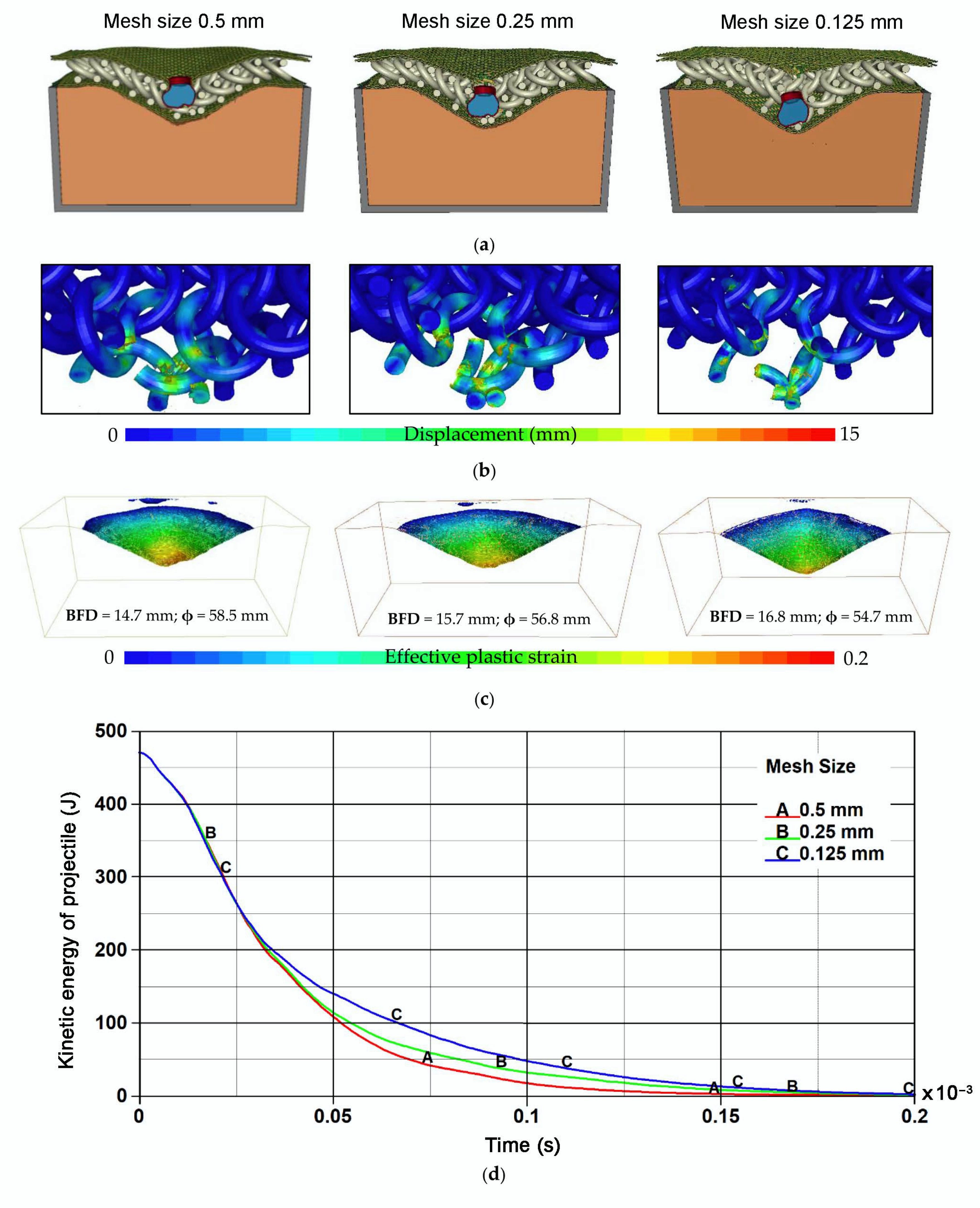
  • Final deformations of the phenomenon components;
  • Distribution of plastic strain in the 3D printed titanium structures;
  • Volumes, shapes and dimensions of characteristic deformation parameters of the ballistic clay;
  • Plots of kinetic energy of the projectile versus time.
Results of simulation for the S1 variant of 3D printed titanium structure are shown in Figure 13. Titanium structures were damaged in the direct projectile interaction zone in both variants of impact points (Figure 13c). Results of simulations indicated that structure S1 was very sensitive to location of impact point. During penetration of the S1 structure at impact point 2 the projectile was deformed in a characteristic way. Due to large air gaps between the structure cells, the deformed projectile took the shape of a truncated cone (Figure 13b). This projectile self-sharpening effect was undesirable because it caused concentration of the impact energy on the smaller area. As a consequence, the smallest diameter of indentation (impact point 2) and volumes of hollows in the ballistic clay were observed after the projectile impacted into the S1 variant of structure at impact point 2. On the other hand, the structure showed high effectiveness when the projectile hit at impact point 1. Values of back face deformation (BFD) obtained for the S1 structure were 14.0–16.1 mm (Figure 13d).
In the S2 3D printed structure variation, individual cells had toroidal shape (Figure 12c). Thanks to that, the S2 structure showed high capability to dissipate the impact energy of the 9 mm projectile. The smooth shape of the cells prevents their blocking during their movement in relation to each other. Only individual cells were damaged and cracked in the area of the projectile impact (Figure 14c). Taking into account the mushroom shape of the projectile after the impact (Figure 14b), it can be concluded that a significant part of impact energy was dissipated to plastic deformation of projectile. Values of BFD obtained for the S2 structure (14.7–14.0 mm) were significantly smaller than in the case of the S1 structure (Figure 13d). Additionally, volumes and diameters of hollows in the ballistic clay (Figure 14d) were much larger than for the S1 structure. This indicated that the smooth toroidal shape of cells has greater potential in bulletproof vest application.
The S3 structure was similar to the S2 variant. The main difference was that individual cells had octagonal forms instead of circular ones (see Figure 12c,d). The S3 structure also showed satisfying energy absorption and dissipation capabilities during the simulations (Figure 15). The depth of indentation in the ballistic clay observed after the impact of the 9 mm FMJ Parabellum projectile was 14.6 mm (Figure 15d) for both impact location points. That indicated that both S2 and S3 structures were much less sensitive to the projectile impact location than variant S1. Significant mushrooming of the projectile demonstrated that the impact energy was dispersed over a larger area. The projectile deformation (Figure 15b) took a similar shape as for the S2 structure. Only individual cells under the projectile impact point were damaged (Figure 15c).
In the last 3D printed structure variation—S4 (Figure 16)—cells had the shape of an octagon with an internal scaffold (Figure 12b). Regarding the shape of the cells, it was predicted that the S4 structure would provide the most efficient absorption and dissipation of the projectile energy. However, results obtained for the S4 structure varied greatly. The structure turned out to be very sensitive to the projectile impact location. On the one hand, structure S4 showed the best protection capability when the projectile hit impact point 2. Although a few cells were damaged the greatest diameter (65.8 mm) and the smallest BFD (12.7 mm) was obtained in that case. On the other hand, when the projectile hit impact point 1 the structure showed the worst energy absorption and dissipation capability; depth of indentation in the ballistic clay was the highest (17.2 mm) in that case. It seemed that the main reason for that lay in the specific shape of a single cell of the S4 structure. In some cases when the loads are distributed particularly unfavorably on the cell it fractures in a specific way forming fragments with sharp edges (Figure 16b). These fragments may cut the aramid layers and significantly decrease their resistance to impact.
Comparing the plots of the kinetic energy of projectiles against time it can be noticed that structure S1 seemed to have the lowest stiffness. The projectile was stopped significantly later than in the case of other variants. Stopping of the projectile was observed in t = 0.2 ms while in the other variants of simulations the projectile velocity reached zero value at of t = 0.15 ms (structures S2, S3) and t = 0.175 ms (structure S4). Additionally, only in the case of the S1 structure did the projectiles come into contact with the aramid layers. In other cases, the projectile was stopped at the titanium layers. It was probably caused by the significantly greater proportion of empty space in the total volume of the titanium layer.
Based on simulation results it can be concluded that the analyzed 3D printed titanium structures together with additional aramid layers are effective against the 9 mm FMJ Parabellum projectile. All the analyzed structures stopped the projectile. Additionally, thanks to the cooperation of adjacent cells, the concentrated energy of the projectile was distributed over a much larger area compared to classical systems based on aramid layers. That was proved by large diameters of hollows in the ballistic clay. However, it should be noted that during the analyses the areal density of structures was not optimized. Structure variants were compared in order to select the most efficient shape of cells that show the greatest potential of application in bulletproof inserts as a layer with high capability of absorption and dissipation of the energy of the impacting projectile. On the basis of the simulation results it was observed that variants S2 and S3 of the structures showed the greatest capability of absorbing and dissipating of the projectile impact energy. Therefore, this structure variant may constitute the initial geometry used in further optimization of shape and areal density of 3D printed structures used in bulletproof vest inserts.

4.2. Mesh Sensitivity Study

In order to check the influence of the finite element size on the damage intensity of the titanium structure during the projectile impact the mesh sensitivity study was carried out. Additional simulations of the S2 structure were performed in which the size of the elements used to describe the cells of the structure the projectile impact zone were decreased (Figure 17). It was considered from 0.5 to 0.25 mm (Figure 17b) and from 0.5 to 0.125 mm (Figure 17c).
Results of simulations carried out for different mesh size were shown in Figure 18.
On the basis of the simulation results it can be concluded that damage intensity of the titanium structures increased together with the decrease of the mesh size (Figure 18b). As a consequence, the kinetic energy of the projectile was distributed on the smaller area (the smallest indention diameter of 54.7 mm), and the highest back face deformation (BFD) = 16.8 mm was observed in the variant where the cells of the titanium structure were modelled with elements of 0.125 mm size (Figure 18c). The most intense absorption and dissipation of the kinetic energy of the projectile was observed in the variant with the coarsest mesh (Figure 18d). Larger size of the elements increased their stiffness and resulted in the elements being eroded later than in cases with refined mesh. To conclude, the developed model of the ballistic impact phenomenon showed moderate mesh sensitivity. In order to decrease the influence of the mesh size on the failure intensity of titanium structures the curves that define plastic failure strain as a function of element size in the *MAT_224-TABULATED_JOHNSON_COOK should be tuned while taking into account the correlation to experimental data.

5. Conclusions

The results of numerical analysis of the ballistic impact of the 9 × 19 mm FMJ Parabellum projectile into 100 × 100 mm composite layered armor containing four variants of 3D printed titanium structures were presented. Numerical models of the phenomenon were developed. Numerical models of individual components were verified against experimental data from the authors’ own research as well as those available in the literature. The models provide proper representation of the actual behavior of materials. This may indicate that the adopted methodology of numerical analysis was correct, but the final verification of the numerical model of the whole phenomenon will be possible after performing experimental tests.
All of the analyzed variants of structures stopped the 9 × 19 mm FMJ Parabellum projectile. Indentations in the ballistic clay after the projectile impact into the analyzed ballistic inserts, were within the range of 12.7–17.2 mm. These values are significantly lower than the limiting BFD value of 44 mm allowed by the standards [42]. On the basis of the simulation results it was observed that variants S2 and S3 of the structures showed the greatest capability of absorbing and dissipating the projectile impact energy. These structures were also less sensitive to the projectile impact location than structures S1 and S4. Therefore, structures S2 and S3 may constitute the initial geometry used in further optimization of shape and areal density of the 3D printed structures used in bulletproof vest inserts. Small indentations in the ballistic clay after the projectile impact into protective structures indicated that they were overweighed and can be optimized to reduce the areal density while providing protection against a 9 × 19 mm FMJ Parabellum projectile.
To sum up, it seems justified to continue this project focused on using 3D printed titanium structures in inserts of bulletproof vests protecting against 9 × 19 mm FMJ Parabellum projectiles.

Author Contributions

Conceptualization, P.Z., M.B. (Marcin Bajkowski) and M.M.; methodology, R.G., K.J., W.B. and M.B. (Miroslaw Bocian); software, P.Z., D.P. and M.M.; validation, M.B. (Marcin Bajkowski) and R.G.; formal analysis, P.Z., K.J. and R.G.; investigation, P.Z., M.B. (Marcin Bajkowski) and M.M.; resources, K.J., M.B. (Miroslaw Bocian) and M.M.; data curation, P.Z., K.J., D.P. and M.B. (Marcin Bajkowski); writing—original draft preparation, P.Z., R.G. and W.B.; writing—review and editing, K.J., M.M. and M.B. (Miroslaw Bocian); visualization, P.Z., W.B., K.J. and D.P.; supervision, K.J., M.B. (Marcin Bajkowski) and M.M.; project administration, P.Z., D.P. and M.B. (Miroslaw Bocian); funding acquisition, M.B. (Marcin BajkowskI) and M.M. All authors have read and agreed to the published version of the manuscript.

Funding

This research was funded by the National Centre for Research and Development of Poland, grant No. TECHMATSTRATEG 2/410049/12/NCBR/2019.

Institutional Review Board Statement

Not applicable.

Informed Consent Statement

Not applicable.

Data Availability Statement

Data sharing is not applicable to this article.

Acknowledgments

Calculations were carried out at the Wroclaw Centre for Networking and Supercomputing (http://www.wcss.pl), grant No. 452.

Conflicts of Interest

The authors declare no conflict of interest.

References

  1. Pach, J.; Mayer, P.; Jamroziak, K.; Polak, S.; Pyka, D. Experimental Analysis of Puncture Resistance of Aramid Laminates on Styrene-Butadiene-Styrene and Epoxy Resin Matrix for Ballistic Applications. Arch. Civ. Mech. Eng. 2019, 19, 1327–1337. [Google Scholar] [CrossRef]
  2. Clifton, S.; Thimmappa, B.H.S.; Selvam, R.; Shivamurthy, B. Polymer Nanocomposites for High-Velocity Impact Applications-A Review. Compos. Commun. 2020, 17, 72–86. [Google Scholar] [CrossRef]
  3. Benzait, Z.; Trabzon, L. A Review of Recent Research on Materials Used in Polymer–Matrix Composites for Body Armor Application. J. Compos. Mater. 2018, 52, 3241–3263. [Google Scholar] [CrossRef]
  4. Fejdyś, M.; Kośla, K.; Kucharska-Jastrząbek, A.; Łandwijt, M. Hybride Composite Armour Systems with Advanced Ceramics and Ultra-High Molecular Weight Polyethylene (UHMWPE) Fibres. Fibres Text. East. Eur. 2016, 24, 79–89. [Google Scholar] [CrossRef]
  5. Crouch, I.G. Critical Interfaces in Body Armour Systems. Def. Technol. 2020. [Google Scholar] [CrossRef]
  6. Da Luz, F.S.; Filho, F.d.C.G.; Oliveira, M.S.; Nascimento, L.F.C.; Monteiro, S.N. Composites with Natural Fibers and Conventional Materials Applied in a Hard Armor: A Comparison. Polymers 2020, 12, 1920. [Google Scholar] [CrossRef]
  7. Fejdyś, M.; Kośla, K.; Kucharska-Jastrząbek, A.; Łandwijt, M. Influence of Ceramic Properties on the Ballistic Performance of the Hybrid Ceramic–Multi-Layered UHMWPE Composite Armour. J. Aust. Ceram. Soc. 2020. [Google Scholar] [CrossRef]
  8. Kurzawa, A.; Pyka, D.; Jamroziak, K.; Bajkowski, M.; Bocian, M.; Magier, M.; Koch, J. Assessment of the Impact Resistance of a Composite Material with EN AW-7075 Matrix Reinforced with α-Al2O3 Particles Using a 7.62 × 39 mm Projectile. Materials 2020, 13, 769. [Google Scholar] [CrossRef] [Green Version]
  9. Kurzawa, A.; Pyka, D.; Jamroziak, K.; Bocian, M.; Kotowski, P.; Widomski, P. Analysis of Ballistic Resistance of Composites Based on EN AC-44200 Aluminum Alloy Reinforced with Al2O3 Particles. Compos. Struct. 2018, 201, 834–844. [Google Scholar] [CrossRef]
  10. Chusov, S.Y.; Yankov, V.P. Investigation of Properties of Titanium Alloys with Mechanically Stable Beta-Structure for Body Armor Application. Tech. Wyrob.Włók. 2009, 17, 54–57. [Google Scholar]
  11. Cimpoeru, S.J.; Alkemade, S.J.; Szymczak, M.; Rupert, N.L.; Green, W.H.; Wells, J.M. Ballistic Assessment of a Low-Cost Ti-6Al-4V Titanium Alloy. Aust. J. Mech. Eng. 2003, 1, 5–9. [Google Scholar] [CrossRef]
  12. Karahan, M.; Jabbar, A.; Karahan, N. Ballistic Impact Behavior of the Aramid and Ultra-High Molecular Weight Polyethylene Composites. J. Reinf. Plast. Compos. 2015, 34, 37–48. [Google Scholar] [CrossRef]
  13. Shtertser, A.A.; Zlobin, B.S.; Kiselev, V.V.; Shemelin, S.D.; Bukatnikov, P.A. Characteristics of Reinforced Ultra-High Molecular Weight Polyethylene During Its Ballistic Penetration. J. Appl. Mech. Tech. Phys. 2020, 61, 471–478. [Google Scholar] [CrossRef]
  14. Jamroziak, K. Evaluation of Gunshot Wounds in Aspect of Injury Criterion. Aktual. Probl. Biomech. 2016, 11, 33–46. [Google Scholar]
  15. Wang, L.; Kanesalingam, S.; Nayak, R.; Padhye, R. Recent Trends in Ballistic Protection. Text. Light Ind. Sci. Technol. 2014, 3, 37–47. [Google Scholar] [CrossRef]
  16. Baranowski, P.; Płatek, P.; Antolak-Dudka, A.; Sarzyński, M.; Kucewicz, M.; Durejko, T.; Małachowski, J.; Janiszewski, J.; Czujko, T. Deformation of Honeycomb Cellular Structures Manufactured with Laser Engineered Net Shaping (LENS) Technology under Quasi-Static Loading: Experimental Testing and Simulation. Addit. Manuf. 2019, 25, 307–316. [Google Scholar] [CrossRef]
  17. Szymczyk, P.; Hoppe, V.; Ziółkowski, G.; Smolnicki, M.; Madeja, M. The Effect of Geometry on Mechanical Properties of Ti6Al4V ELI Scaffolds Manufactured Using Additive Manufacturing Technology. Arch. Civ. Mech. Eng. 2020, 20, 1–13. [Google Scholar] [CrossRef] [Green Version]
  18. Horn, K.; Biever, K.; Burkman, K.; Sheikh, P.D.; Jamison, L.; Kolb, M. Lightening Body Armor: Arroyo Support to the Army Response to Section 125 of the National Defense Authorization Act for Fiscal Year 2011; Report No. W74V8H-06-C-0001; United States Army: Santa Monica, SM, USA, 2011.
  19. Kristoffersen, M.; Costas, M.; Koenis, T.; Brøtan, V.; Paulsen, C.O.; Børvik, T. On the Ballistic Perforation Resistance of Additive Manufactured AlSi10Mg Aluminium Plates. Int. J. Impact Eng. 2020, 137. [Google Scholar] [CrossRef]
  20. Ngo, T.D.; Kashani, A.; Imbalzano, G.; Nguyen, K.T.Q.; Hui, D. Additive Manufacturing (3D Printing): A Review of Materials, Methods, Applications and Challenges. Compos. Part B Eng. 2018, 143, 172–196. [Google Scholar] [CrossRef]
  21. Dunaj, P.; Berczyński, S.; Miądlicki, K.; Iskra, I.; Niesterowicz, B. Increasing Damping of Thin-Walled Structures Using Additively Manufactured Vibration Eliminators. Materials 2020, 13, 2125. [Google Scholar] [CrossRef]
  22. Garcia-Gonzalez, D.; Rusinek, A.; Jankowiak, T.; Arias, A. Mechanical Impact Behavior of Polyether-Ether-Ketone (PEEK). Compos. Struct. 2015, 124, 88–99. [Google Scholar] [CrossRef] [Green Version]
  23. Szymczyk, P.; Ziółkowski, G.; Junka, A.; Chlebus, E. Application of Ti6Al7Nb Alloy for the Manufacture of Biomechanical Functional Structures (BFS) for Custom-Made Bone Implants. Materials 2018, 11, 971. [Google Scholar] [CrossRef] [PubMed] [Green Version]
  24. Yuan, M.Q.; Liu, Y.; Gong, Z.; Qian, X.M. The Application of PA/CF in Stab Resistance Body Armor. IOP Conf. Ser. Mater. Sci. Eng. 2017, 012027. [Google Scholar] [CrossRef] [Green Version]
  25. Connors, M.; Yang, T.; Hosny, A.; Deng, Z.; Yazdandoost, F.; Massaadi, H.; Eernisse, D.; Mirzaeifar, R.; Dean, M.N.; Weaver, J.C.; et al. Bioinspired Design of Flexible Armor Based on Chiton Scales. Nat. Commun. 2019, 10, 1–13. [Google Scholar] [CrossRef] [Green Version]
  26. Costas, M.; Morin, D.; de Lucio, M.; Langseth, M. Testing and Simulation of Additively Manufactured AlSi10Mg Components under Quasi-Static Loading. Eur. J. Mech. A/Solids 2020, 81, 103966. [Google Scholar] [CrossRef]
  27. Masood, S.H.; Ruan, D.; Rajapatruni, P. Mechanical Performance of Plymetal Structures Subjected to Impact Loading. Int. J. Prot. Struct. 2018, 9, 65–76. [Google Scholar] [CrossRef]
  28. Zhao, L.; Qian, X.; Sun, Y.; Yuan, M.; Tang, F.; Zhao, Y.; Zhang, Q.; Chen, Y. Ballistic Behaviors of Injection-Molded Honeycomb Composite. J. Mater. Sci. 2018, 53, 14287–14298. [Google Scholar] [CrossRef]
  29. Płatek, P.; Rajkowski, K.; Cieplak, K.; Sarzyński, M.; Małachowski, J.; Woźniak, R.; Janiszewski, J. Deformation Process of 3D Printed Structures Made from Flexible Material with Different Values of Relative Density. Polymers 2020, 12, 2120. [Google Scholar] [CrossRef]
  30. Platek, P.; Sienkiewicz, J.; Janiszewski, J.; Jiang, F. Investigations on Mechanical Properties of Lattice Structures with Different Values of Relative Density Made from 316L by Selective Laser Melting (SLM). Materials 2020, 13, 2204. [Google Scholar] [CrossRef]
  31. Kluczyński, J.; Sniezek, L.; Grzelak, K.; Janiszewski, J.; Płatek, P.; Torzewski, J.; Szachogłuchowicz, I.; Gocman, K. Influence of Selective Laser Melting Technological Parameters on the Mechanical Properties of Additively Manufactured Elements Using 316L Austenitic Steel. Materials 2020, 13, 1449. [Google Scholar] [CrossRef] [Green Version]
  32. Płatek, P.; Baranowski, P.; Janiszewski, J.; Kucewicz, M. Problems of Deformation and Damage Studies of Additively Manufactured Regular Cellular Structures. In Handbook of Damage Mechanics: Nano to Macro Scale for Materials and Structures; Voyiadjis, G.Z., Ed.; Springer: New York, NY, USA, 2020; pp. 1–33. [Google Scholar] [CrossRef]
  33. Bajkowski, M.; Grygoruk, R.; Nita, Z.; Floriańczyk, A. Method for Producing Additional Ballistic Insert and the Additional Ballistic Insert for Bulletproof. Jackets. Patent PL224964, 28 February 2017. [Google Scholar]
  34. Gmbh, T.A. Teijin Aramid @ Techtextile Middle East Symposium. Available online: https://www.intersecexpo.com/uploads/editor_images/file/ReneLohmann-DubaiTTS2014_SHOW-locked.pdf (accessed on 20 November 2020).
  35. Pawlak, A.; Szymczyk, P.; Ziolkowski, G.; Chlebus, E.; Dybala, B. Fabrication of Microscaffolds from Ti-6Al-7Nb Alloy by SLM. Rapid Prototyp. J. 2015, 21, 393–401. [Google Scholar] [CrossRef]
  36. Del Guercio, G.; Galati, M.; Saboori, A.; Fino, P.; Luliano, L. Microstructure and Mechanical Performance of Ti–6Al–4V Lattice Structures Manufactured via Electron Beam Melting (EBM): A Review. Acta Metall. Sin. (Engl. Lett.) 2020, 33, 183–203. [Google Scholar] [CrossRef] [Green Version]
  37. Cotton, R.; Palanisamy, S.; Avdeev, M.; Jarvis, T.; Henry, C.; Cuiuri, D.; Balogh, L.; Rashid, R.A.R. Diffraction Line Profile Analysis of 3D Wedge Samples of Ti-6Al-4V Fabricated Using Four Different Additive Manufacturing Processes. Metals 2019, 9, 60. [Google Scholar] [CrossRef] [Green Version]
  38. STANAG 4090. Technical Performance Specification Providing for the Interchangeability of 9 mm × 19 Ammunition; North Atlantic Treaty Organization (NATO): Brussels, Belgium, 2020. [Google Scholar]
  39. Panowicz, R.; Janiszewski, J.; Kochanowski, K. Effects of Sample Geometry Imperfections on the Results of Split Hopkinson Pressure Bar Experiments. Exp. Tech. 2019, 43, 397–403. [Google Scholar] [CrossRef] [Green Version]
  40. Chapman, D.J.; Radford, D.; Walley, S.M. A History of the Taylor Test and Its Present Use in the Study of Lightweight Materials. In 3rd Light-Weight Armour Group Workshop. Design and Use of Light-Weight Materials; Teixeria-Dias, F., Dodd, B., Lach, E., Schulz, P., Eds.; Universidade de Aveiro: Aveiro, Portugal, 2005; pp. 12–24. [Google Scholar]
  41. Kruszka, L.; Magier, M.; Zielenkiewicz, M. Experimental Analysis of Visco-Plastic Properties of the Aluminium and Tungsten Alloys by Means of Hopkinson Bars Technique. Appl. Mech. Mater. 2014, 566, 110–115. [Google Scholar] [CrossRef]
  42. Mukasey, M.B.; Sedgwick, J.L.; Hagy, D.W. Ballistic Resistance of Body Armor; U.S. Department of Justice Office of Justice Programs: Washington, DC, USA, 2008; pp. 1–89.
  43. LS-DYNA® Keyword User’s Manual; LS-DYNA R12, (r:13109); Livermore Software Technology (LST): Pittsburgh, PA, USA, 2020; Volume I.
  44. Materials Modeles. In LS-DYNA® Keyword User’s Manual; LS-DYNA R12, (r:13191); Livermore Software Technology (LST): Pittsburgh, PA, USA, 2020; Volume II.
  45. Bocian, M.; Jamroziak, K.; Kosobudzki, M. Analysis of Material Punching Including a Rotational Speed of the Projectile. Solid State Phenom. 2015, 220–221, 571–576. [Google Scholar] [CrossRef]
  46. Mazurkiewicz, Ł.; Małachowski, J.; Baranowski, P. Optimization of Protective Panel for Critical Supporting Elements. Compos. Struct. 2015, 134, 493–505. [Google Scholar] [CrossRef]
  47. Mackiewicz, A.; Pyka, D.; Pach, J.; Jamroziak, K.; Bocian, M. Comparison of Numerical Modelling Methods of Innovative Materials for Ballistic Shields. In Advanced Materials for Defense; Fangueiro, R., Rana, S., Eds.; Springer: Berlin/Heidelberg, Germany, 2020; pp. 119–127. [Google Scholar]
  48. Hernandez, C.; Maranon, A.; Ashcroft, I.A.; Casas-Rodriguez, J.P. Inverse Methods for the Mechanical Characterization of Materials at High Strain Rates. EPJ Web Conf. 2012, 26, 04022. [Google Scholar] [CrossRef]
  49. Coefficient of Friction. Available online: https://www.teachengineering.org/content/nyu_/activities/nyu_heavy/nyu_heavy_activity1_coftable.pdf (accessed on 8 January 2021).
  50. Nilakantan, G.; Keefe, M.; Gillespie, J.W.; Bogetti, T.A. Novel Multi-Scale Modeling of Woven Fabric. In 10th International LS-DYNA® Users Conference; Mindle, W.L., Ed.; Livermore Software Technology Corporation: Dearbon, MI, USA, 2008; pp. 19–38. [Google Scholar]
  51. Nilakantan, G.; Nutt, S. Effects of Ply Orientation and Material on the Ballistic Impact Behavior of Multilayer Plain-Weave Aramid Fabric Targets. Def. Technol. 2018, 14, 165–178. [Google Scholar] [CrossRef]
  52. Nilakantan, G.; Keefe, M.; Bogetti, T.A.; Gillespie, J.W. Multiscale Modeling of the Impact of Textile Fabrics Based on Hybrid Element Analysis. Int. J. Impact Eng. 2010, 37, 1056–1071. [Google Scholar] [CrossRef] [Green Version]
  53. Haight, S.; Wang, L.; Du Bois, P.; Carney, K.; Kan, C. Development of a Titanium Alloy Ti-6Al-4V Material Model Used in LS-DYNA; Report DOT/FAA/TC-15/23; U.S. Department of Transportation: Washington, DC, USA, 2016; 1, p. 353.
  54. Burian, W.; Żochowski, P.; Gmitrzuk, M.; Marcisz, J.; Starczewski, L.; Juszczyk, B.; Magier, M. Protection Effectiveness of Perforated Plates Made of High Strength Steel. Int. J. Impact Eng. 2019, 126, 27–39. [Google Scholar] [CrossRef]
  55. Meyer, H.W.; Kleponis, D.S. Modeling the High Strain Rate Behavior of Titanium Undergoing Ballistic Impact and Penetration. Int. J. Impact Eng. 2001, 26, 509–521. [Google Scholar] [CrossRef]
Figure 1. Variants of 3D printed titanium structures chosen for analyses: (a) structure of the S1 type; (b) structure of the S2 type; (c) structure of the S3 type and (d) structure of the S4 type.
Metals 11 00225 g001
Figure 2. Configuration of the analyzed ballistic insert.
Metals 11 00225 g002
Figure 3. Example of additively manufactured cell interlacing: 1—cells forming the grid structure; 2—internal circuit of the adjacent grid structure element; 3—external circuit of the adjacent grid structure element.
Metals 11 00225 g003
Figure 4. Microstructure of the Ti-6Al-4V titanium alloy after the selective laser melting (SLM) process (scanning microscopy). Distribution of α’-phase lath martensite on the background of the β-phase.
Metals 11 00225 g004
Figure 5. Microstructure of the Ti-6Al-4V titanium alloy after the SLM process (light microscopy) etched with Kroll’s reagent.
Metals 11 00225 g005
Figure 6. The 9 × 19 mm FMJ Parabellum bullet: (a) single cartridge; (b) projectile cross section; (c) projectile and (d) dimensions of projectile.
Metals 11 00225 g006
Figure 7. Experimental test of quasi-static penetration of Twaron CT 750 aramid fabric: (a) test stand and (b) example of results.
Metals 11 00225 g007
Figure 8. Deformations of the 9 mm FMJ Parabellum projectile obtained in the experiments and simulations: (a) impact velocity of 100 m/s; (b) impact velocity of 126 m/s and (c) impact velocity of 143.8 m/s.
Metals 11 00225 g008
Figure 9. Numerical model of the analyzed projectile impact phenomenon.
Metals 11 00225 g009
Figure 10. Ballistic clay validation: (a) Initial position and (b) impactor indentation in clay.
Metals 11 00225 g010
Figure 11. Discretization of Twaron CT 750 fabric: (a) Schematic of a plain-woven and (b) plain woven textile showing the warp and fill.
Metals 11 00225 g011
Figure 12. Discretization of the 3D printed structures made of Ti-6Al-4V titanium alloy: (a) structure S1; (b) structure S4; (c) structure S2 and (d) structure S3.
Metals 11 00225 g012
Figure 13. Results of simulation for S1 structure: (a) location of the impact point; (b) final deformation; (c) distribution of effective plastic strain in the titanium structure; (d) shape of the hollow in the ballistic clay and (e) plot of the projectile energy against time.
Metals 11 00225 g013
Figure 14. Results of simulation for S2 structure: (a) location of the impact point; (b) final deformation; (c) distribution of effective plastic strain in the titanium structure; (d) shape of the hollow in the ballistic clay and (e) plot of the projectile energy against time.
Metals 11 00225 g014
Figure 15. Results of simulation for S3 structure: (a) location of the impact point; (b) final deformation; (c) distribution of effective plastic strain in the titanium structure; (d) shape of the hollow in the ballistic clay and (e) plot of the projectile energy against time.
Metals 11 00225 g015
Figure 16. Results of simulation for S4 structure: (a) location of the impact point; (b) final deformation; (c) distribution of effective plastic strain in the titanium structure; (d) shape of the hollow in the ballistic clay and (e) plot of the projectile energy against time.
Metals 11 00225 g016
Figure 17. Variations of discretization used in the mesh sensitivity study: (a) base size; (b) mesh size 0.5–0.25 mm and (c) mesh size 0.5–0.125 mm.
Metals 11 00225 g017
Figure 18. Results of simulations performed in the mesh sensitivity study: (a) final deformation; (b) distribution of effective plastic strain in the titanium structure; (c) shape of the hollow in the ballistic clay and (d) plot of the projectile energy against time.
Metals 11 00225 g018
Table 1. Properties of Twaron CT 750 aramid fabric [34].
StyleType Warp/WeftWeaveSet (per 10 cm) Warp/WeftAreal Density (g/m2)Thickness (mm)Minimum Break Strength (N/5 cm × 1000) Warp/Weft
CT 7502000plain69/694600.7016.5/18.0
Table 2. Parameters of the * MAT_107-MODIFIED_JOHNSON_COOK model for projectile.
SpecificationRO, (Tonnes)E, (MPa)PR,
(-)
A, (MPa)B, (MPa)n,
(-)
C,
(-)
m,
(-)
D1,
(-)
D2,
(-)
D3,
(-)
D4,
(-)
D5,
(-)
Lead-Core1.01 × 10−818.4 × 1030.4224401.000.011.0030000
Brass-Jacket8.52× 10−911.5× 1040.312068990.420.011.68-WC1414--
RO—density; E—Young’s modulus; PR—Poisson’s ratio; A—yield strength of the material; B—strain hardening constant; n—strain hardening exponent; C—strengthening coefficient of strain rate; m—thermal softening exponent; D1, D2, D3, D4 and D5—constants.
Table 3. Parameters of the *MAT_018- POWER_LAW_PLASTICITY model for ballistic clay.
SpecificationRO, (Tonnes)E,
(MPa)
PR,
(-)
K,
(MPa)
N,
(-)
SRC,
(s–1)
SRP,
(-)
SIGY, (MPa)EPSF,
(-)
VP,
(-)
Source
Ballistic clay187814.20.490.240.0140002.51[48]
RO—density; E—Young’s modulus; PR—Poisson’s ratio; K—material constant; N—strain rate sensitivity coefficient; SRC—strain rate parameter C for Cowper–Symonds strain rate model; SRP—strain rate parameter P for Cowper–Symonds strain rate model; SIGY—yield strength; EPSF—plastic failure strain for element deletion; VP—formulation for rate effects.
Table 4. Parameters of the *MAT_002-OTHOTROPIC_ELASTIC model for Twaron CT 750 fabric.
SpecificationRO, (Tonnes)EA,
(MPa)
EB,
(MPa)
EC,
(MPa)
PRBA,
(-)
PRCA,
(-)
PRCB,
(-)
GAB, (MPa)GBC, (MPa)GCA, (MPa)Source
Twaron CT 7501.158 × 10−962,80062862800031,00015831,000[50,51,52]
RO—density; EA—Young’s modulus in 𝑎-direction; EB—Young’s modulus in 𝑏-direction; EC—Young’s modulus in 𝑐-direction; PRBA—Poisson ratio, 𝑏𝑎; PRCA—Poisson ratio, 𝑐𝑎; PRCB—Poisson ratio, 𝑐𝑏; GAB—shear modulus, 𝑎𝑏; GBC—shear modulus, 𝑏𝑐; GCA—shear modulus, 𝑐𝑎.
Publisher’s Note: MDPI stays neutral with regard to jurisdictional claims in published maps and institutional affiliations.

