Microstructural Evolutions and its Impact on the Corrosion Behaviour of Explosively Welded Al/Cu Bimetal
by
 ,
,
Mohammad Reza Jandaghi
1,*, 
Abdollah Saboori
2 ,
,
Gholamreza Khalaj
3 and
Mohammadreza Khanzadeh Ghareh Shiran
4 1
Department of Advanced Materials, WorldTech Scientific Research Center (WT-SRC), 1778864384 Tehran, Iran
2
Department of Applied Science and Technology, Politecnico Di Torino, Corso Duca Degli Abruzzi 24, 10129 Torino, Italy
3
Young Researchers and Elites Club, Saveh Branch, Islamic Azad University, 3919715179 Saveh, Iran
4
Center for Advanced Engineering Research, Majlesi Branch, Islamic Azad University, 8631656451 Isfahan, Iran
*
Author to whom correspondence should be addressed.
Metals 2020, 10(5), 634; https://doi.org/10.3390/met10050634
Submission received: 12 April 2020
/
Revised: 9 May 2020
/
Accepted: 11 May 2020
/
Published: 13 May 2020
(This article belongs to the Special Issue Microstructure and Properties of Metallic Heat-Affected Zones)
Abstract
:In this study, the microstructural evolutions and corrosion resistance of aluminium/copper joint fabricated through explosive welding process have been thoroughly investigated, while stand-off distance was variable. Microstructural analyses demonstrate that, regardless of grain refinement in the welding boundary, increasing the stand-off space is followed by a higher thickness of the localized melting pool. X-Ray diffraction (XRD) and energy-dispersive X-ray spectroscopy (EDS) analyses recognized the binary intermetallic layers as a combination of Al2Cu and AlCu. Polarization and electrochemical impedance spectroscopy (EIS) corrosion tests revealed that a higher stand-off distance resulted in the increment of corrosion potential, current rate, and concentration gradient at the interface owing to the remarkable kinetic energy of the collision, which impaired corrosion resistance.
1. Introduction
Explosive welding process can be employed as a novel method for the fabrication of a joint between two surfaces, which have a certain distance from each other, through controlling the energy of the explosion and high-speed collision of surfaces [1]. As a result of the collision of two surfaces with each other, a localized plastic deformation field is created at the interface that forms a band with a metallurgical bond between the welding components [2]. High impact pressure acts as a high-speed jet between two connecting surfaces and aids the removal of all contaminants from the surface to provide a clean joint at the welding interface. The formation of such a jet would be one of the essential required conditions for the formation of adequate bonding in explosive welding [3]. The main advantage of explosive welding as a non-fusion method in the industrial applications would be related to its capability to form a bonding and/or coating between similar/dissimilar metals as two or multilayers [4]. The absence of heat in this process could prevent numerous common problems compared to other joining methods, like fusion welding, hot rolling, or hot forging processes [5,6]. Kengkla et al. [7] have studied the effect of intermetallic compounds on the corrosion behaviour of triple-layered aluminium/steel explosive linkage in military industries. Their results confirmed the formation of Al3Fe, Al5Fe2 intermetallic compounds at the connection interface created a cathodic state for aluminium and anodic one for steel. Hence, some sort of preferential corrosion attack occurred near the boundaries between aluminium and intermetallic compounds. Mudali et al. [8] have investigated the corrosion manner in explosion bond of titanium alloy to 304 stainless steel. Their observations proved that the flexural strength of the joint fulfilled the standard limits in the nitric acid environment, and corrosion attack was dominantly concentrated on the welding interface. Acarer [9] considered the corrosion behaviour of the explosive connection between the aluminium and copper. Based on their report, galvanic corrosion occurred at the junction site, and due to high electronegativity, the aluminium side had the larger anodic feature and corroded more than the copper side. Kahraman et al. [10] studied the corrosion resistance of an explosively joint between titanium and stainless steel. They declared that, in corrosive media, increasing the amount of explosive charge, followed by adding to the mass of the connected plates due to the higher strain, led to the formation of extra oxide layers on the surface. They also [11] examined the corrosion behaviour of explosive joints between Ti-6Al-4V and aluminium plates. Corrosion outputs demonstrated that weight loss rate in both materials in starting the corrosion was remarkably high and attenuated during the test. Moreover, increasing the amount of plastic deformation owing to explosion charge increment resulted in further weight loss during the corrosion tests. Zarei et al. [12] compared the behaviour of fusion and explosive welding of Inconel 625 and plain carbon steel in a corrosive media. They found that, in the fusion welding, corrosion resistance of a joint has higher uniformity because of chemical heterogeneities owing to micro-segregation and the formation of secondary destructive phases, beside their accumulation at the fusion joint that prevents the formation of stable passive layers.
However, prior researchers have studied different aspects regarding the explosive welding between aluminium alloys and other metallic Mg [13,14], Ti [15,16,17], Ni [18], Fe [19,20,21], and Cu [22,23,24]. For instance, Gharah Shiran et al. studied the effect of heat treatment of the microstructure and mechanical properties of multilayer Cu/Al/Cu explosive welded joints [22]. Carvalho et al. investigated the role of the flyer materials on the interface of Al/Cu explosive welds [23]. Recently, in another work, Kaya evaluated the effect of explosive ratio on the properties of the bonding interface [24]. However, up to now, far too little attention has been paid to the corrosion behaviour of explosively welded Al/Cu. Hence, the main aim of this study is to explore the corrosion behaviour and microstructure changes in double-layered aluminium-copper plates produced by the explosive welding technique using various stand-off distances. Therefore, the corrosion mechanism of the binding zone in 3.5% NaCl solution was characterized. With scrutiny, the impact of stand-off distance on the corrosion behaviour of explosive joint interface using potentiodynamic polarization and electrochemical impedance spectrophotometry, has scarcely been considered by previous researchers. Thus, the present study sheds light on this issue.
2. Materials and Methods
2.1. Basic Materials
Al 5083 and copper-tin plates sectioned in 260 mm × 260 mm × 3 mm for the flying and 230 mm × 230 mm × 5 mm for base specimen, respectively. The chemical composition of employed plates was evaluated using emission spectrometry, and results are listed in Table 1.
2.2. Explosive Welding Process
The surfaces of specimens (Al 5083 and copper sheets) were mechanically polished and subsequently cleaned by the acetone solution right before the welding process. The explosion mixture composed from Amatol 95.5 (made by combining Trinitrotoluene (5%) and Ammonium Nitrate (95%) at a speed of 2507 m/s) and an M8 detonator. To set up the desired plates for operating the explosive welding, applied concrete platform covered with a bed of fine sand as an intermediate and buffer layer. Likewise, in order to create the designed stand-off distances in each test, copper wires with adequate diameters, and with the height of designed stand-off distances set, were placed between the plates. The parallel alignment system was determined for the welding procedure [25]. A schematic image of explosive welding procedure is presented in Figure 1.
The welding process was performed through changing the stand-off distance and explosive load. Details of the test conditions are shown in Table 2. The phrase of an explosive charge in Table 2 points to the weight ratio of explosive to flying plate, which was derived from the following expression:
(Explosive density × explosive thickness)/(density of the flying plate × flying plate thickness).
2.3. Microstructural Characterization
Specimens with 10 mm × 10 mm dimensions were sectioned from thickness and surface of as-annealed and joint plates using a wire-cut machine. Metallography preparations performed using SiC mechanical grinding up to P#4000, and thereafter the final surface polishing was executed by the aid of diamond paste, down to 1 μm. At last, the surface of polished samples was adequately washed by alcohol and dried. Thereafter, as-polished surfaces were chemically etched using a mixture of Glyceregia solution (glycerol + nitric acid + hydrochloric acid) and hydrofluoric acid, respectively. The microstructure of the interfacial evolutions and intermetallic compounds were characterized by employing an Olympus optical microscope (OM) (Olympus, Tokyo, Japan) equipped with polarization lens in various magnifications. Phase characterization was carried out using X-ray diffraction (XRD) analysis which was performed on a Philips X’Pert diffractometer (Philips analytical, Almelo, Netherlands) using Cu Kα radiation, a tube voltage of 40 kV, and a tube current of 40 mA. Moreover, a VEGA MIRA3 scanning electron microscope (SEM) (TESCAN, Kohoutovice, Czech Republic) equipped with an EDS detector was used to evaluate the thickness and morphological variation of intermetallic layers.
2.4. Electrochemical Test
In order to evaluate the corrosion behaviour of explosively welded segments in seawater solution (3.5% NaCl), a three-electrode electrochemical cell having a capacity of 500 mL was utilized as corrosive media for the polarization and electrochemical impedance spectroscopy (EIS) exams. Samples were prepared with dimensions of 10 mm × 10 mm. The base metals were coated, and the joint was exposed to the electrolyte. A supersaturated calomel electrode (SCE) and a platinum electrode were used as the reference electrode and auxiliary electrode, respectively. All the electrochemical tests were conducted by the aim of EG & G device (Model M1025, EG & G, Gaithersburg, MD, USA) and Pro-Power suit 2.20.0 software@ (Ametek, Oak Ridge, TN, USA). Corrosion current (Icorr.) and potential (ECP) were examined using a potentiodynamic polarization test executed with a scan rate of 1 mV/s and potential varying from −250 mV below the open circuit potential (OCP) to 250 mV above the OCP. An electrochemical impedance spectroscopy (EIS) test was conducted in a frequency range of 100 kHz to 10 MHz and 10 mV around the OCP. ZSimpWin 3.22 software (Ametek, Oak Ridge, TN, USA) was employed to analyze the EIS outputs. Meanwhile, the required time to reach the steady state was 90 min.
3. Results and Discussions
3.1. Microstructure
OM micrographs showing the configuration of the grain of primary annealed aluminium and copper specimens are exhibited in Figure 2. As shown, in both archetypes (Al and Cu), grains had semi-equiaxed geometry before explosive welding. Further, the Cu sample had some twinning within its structure from the beginning.
Figure 3 shows the interfacial appearance formed in the welding boundary of explosively encountered plates. As can be seen, the joint lap (Al 5083/Cu) was formed by some disorder waves.
Apparently, during the joining process, a wide localized fusion layer is formed at the interface of the joint with a stand-off distance of 2.5 mm, which could be attributed to the high stand-off distance and tangible difference in the density of welded alloys. As known, two intersections of metal/metal and metal/solidified melted metal can be formed at the interface of explosively welded alloys. In addition to the minimum speed of the flying plate, a minimum amount of collision kinetic energy is required for bonding. Due to the encounter of flying plates, consumed kinetic energy converts into thermal energy which consequence in the deformation of the collisional surface. In the cases that the amount of plastic deformation is insufficient, short waves are created, and the localized melting zone is not developed. Increasing the strike kinetic energy could intensify the severe plastic deformation at the bottom and crest of the waves. Such high encounter energy could generate some vortexes at the interface and lead to the formation of localized melting zones in the welding junction. Different parameters might have a contribution to the formation of such zones. High pressures due to the shock waves of the explosion, severe plastic deformation and adiabatic heat releasement due to the trapped vortex in front of some waves as a consequence of transformation of kinetic energy into thermal after the collision and finally adiabatic heat raised from trapped gas between the plates were the highlight contributors. These areas were surrounded by cold metal chilled with a high cooling rate of 105–107 K/s [26].
Based on Figure 3b, Al/Cu joint interface with the stand-off distance of 2 mm is almost flat. Such a confirmation of interface compared to the S1 sample was due to a decline in the stand-off distance and subsequent kinetic energy of clash. Similar to the S1 specimen, there are localized melting areas in the welding boundary. However, a lower stand-off distance leads to a lower thickness of these areas. Another worthy point in this figure was the creation of some cracks in the localized melting zones, which might be due to the formation of brittle intermetallic compounds in these regions. Macrograph of the welding interface of the S3 sample is depicted in Figure 3c. As can be seen, despite more uniform and proper joining, the formation of localized melting zones was unavoidable, and it formed as a thick layer again. In S1 specimen, the maximum stand-off distance resulted in a maximum melting thickness formation, whereas a thinner melting zone of S2 and S3 compared with S1 was a direct consequence of the lower stand-off distances.
Optical micrographs showing the microstructural evolution around the joining interface of S2 is exhibited in Figure 4. The microstructure of the deformed zone in the Cu side of the interface is shown in Figure 4a. As can be seen, severe plastic deformation due to the explosion waves resulted in grains compaction and formation of some mechanical twining beside pre-existed ones. Chulist et al. [27] reported the same semi-equiaxed characteristics about the microstructure of explosively collided aluminium to titanium. On the other hand, grains gradient in the aluminium side of the joining interface is depicted in Figure 4b. According to the image, a combination of deformation owing to explosive strike and released heat after the collision led to the formation of fine, semi-equiaxed grains. Likewise, adjacent regions to the interface were somewhat affected by explosive encounter and consist of finer grains. This finding is in line with Fronczek et al. who have also reached to same microstructure on the explosive welding of Al/Ti bimetal [28]. According to Figure 4a,b, apart from the grain’s geometry, the closest grains to explosive collision forehead (welding interface) always have the finest size. The morphology and size gradient of grains from the welding zone to the base metals depend on the hitting severity and pre-collision strength of engaged sheets. Figure 4c,e shows that there are some fragmented pieces and wave-like flows of Cu in the aluminium matrix, which had not enough time to react with Al and form secondary phases. Therefore, they were trapped in the aluminium matrix as unreacted elements and, interestingly, it was found that the ultrafine grains formed around these pieces (Figure 4d).
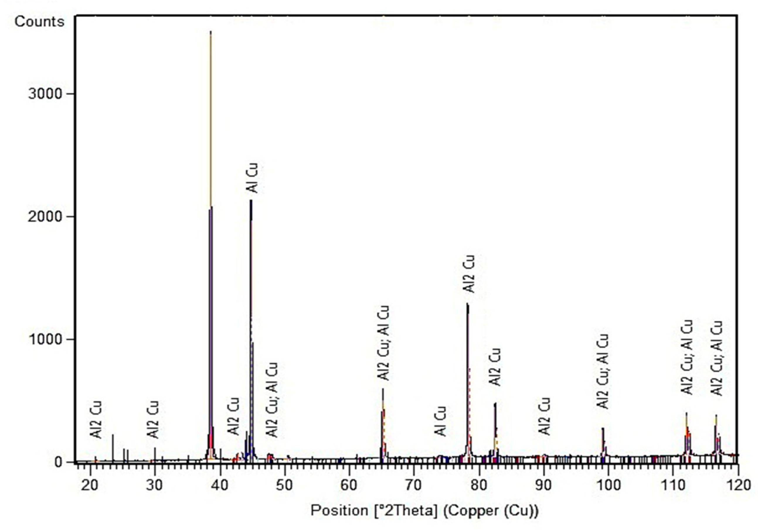
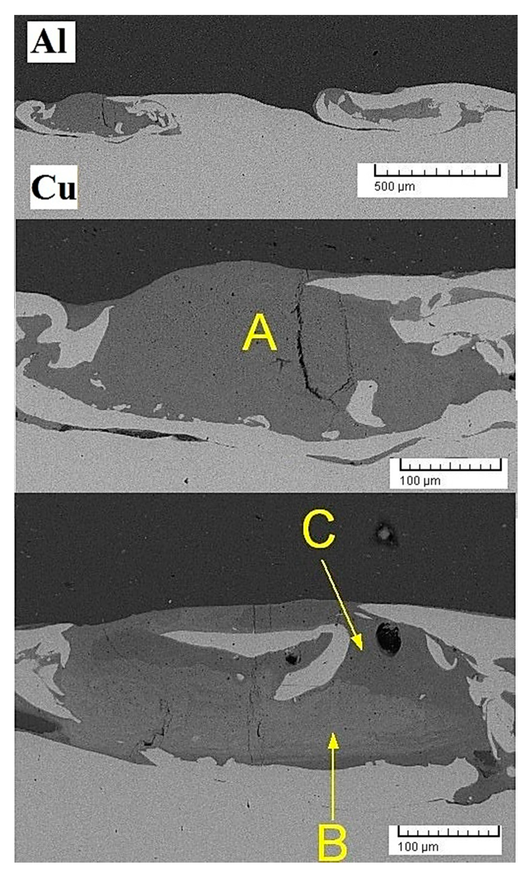
Furthermore, the welding interface has some wave-like serration. The origin of such a phenomenon has been thoroughly elucidated by Chu et al. via an investigation of the explosive welding of Fe/Ti bimetal [29]. They noticed some interesting key points in this realm. They reported that besides the formation of ultrafine grains at the intersection of explosive welded sheets, welding boundary is significantly susceptible to form ultrafine intermetallic layers. Furthermore, the highest heat releases in the welding boundary and interface tolerate the maximum effective strain that induces both sheets to form a wavy structure during the collision. Such conformation is also generated in the intersection of current Al/Cu bimetal (Figure 4d,e). To ascertain a preliminary insight into the nature of formed intermetallic layers after explosive welding, the XRD pattern of the welding boundary of the S1 sample is precisely analyzed (Figure 5). As can be seen, AlCu and Al2Cu phases were two essential components at the welding interface. Supplementary characterization to distinguish the distribution of second phase components performed getting SEM analysis from Al/Cu interface. Accordingly, SEM micrographs of Figure 6, Figure 7 and Figure 8 shed light on the nature of intermetallic particles in the different segments of the welding intersections. Figure 6 shows the intermetallic layer formed at the interface of the specimen S1. The local melting layer is obviously detectable in this figure. Based on the measurements, the thickness of the local melting layer is about 150 µm. Table 2 depicts the EDS analysis of localized melted layer shown in Figure 6. Accordingly, the chemical composition of the localized melted layer in point A includes 74.49% Al, 23.76% Cu and 1.75% Mg (at.%), in point B was 68.51% Al, 30.43% Cu, and 1.06% Mg (at.%), and in point C it reached 80.05% Al, 18.68% Cu, and 1.56% Mg (at.%), which confirms the formation of Al2Cu compound. At point C, the high atomic percentage of aluminium led to the darker appearance of the localized melting layer compared to point B. The formation of the frozen local melting zone could be attributed to stirring of base and flying plates due to the spinning of jumper jet trapped at the interface. Meanwhile, some cracks were formed in the localized melting region (Figure 6), considering the brittle nature of Al/Cu compounds [30]. In fact, the formation of such cracks could be attributed to the remarkable fragility of this region as well as the solidification contraction [31]. Indeed, it can be highlighted that the solidification of the melted zone in this work is rather similar to that one occurs during the soldering or brazing technology that is presented in the literature [32]. For instance, in the soldering/brazing of Ni/Al/Ni, at first, Al3Ni2 and Al3Ni phases were formed the same as the Al2Cu and AlCu phases which were formed in this work [32]. As a matter of fact, the absence of AlCu phase implies that the solidification was metastable as a result of being rapid, and Al2Cu was formed as a consequence of partitioning between liquidous and the metastable solidus. This finding is in line with previous works [33,34]. In fact, it is believed that the rapid solidification at the welding interface can be a segregation-less and diffusion-less phenomenon [34,35].
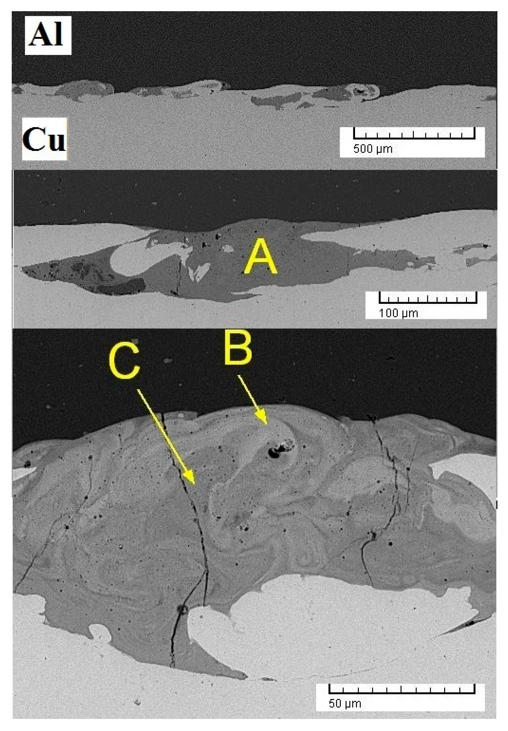
Figure 7 shows the SEM micrographs of the specimen S2. Based on measurements, the thickness of the localized melting layer in this sample (about 100 µm) was less than S1, and such a difference would have originated from the approaching the sheets together and decline in stand-off distance before their explosive collision. The joint interface in S2 appears to be flatter than S1, which is another side effect of reducing the stand-off distance.
Table 3 shows the EDS analysis of the localized melted layer depicted in Figure 7. As can be seen, the chemical composition of the localized melted layer in point A includes 75.69% Al, 21.21% Cu and 3.09% Mg (at.%), in point B have 53.90% Al, 46.10% Cu (at.%), and in point C contains 66.17% Al, 31.66% Cu, and 1.31% Mg (at.%), which confirms the formations of Al2Cu, AlCu, and Al2Cu, respectively. Comparing the atomic percentage of these elements in S1 and S2 points, obviously, the atomic separation at the intersection of localized melting of S2 was lower, which could be attributed to the reduction of stand-off distance. Meanwhile, some cracks were also found in the localized melting region (Figure 7), which is directly due to the formation of brittle intermetallic phases of Al/Cu in concentrated melting layer caused by mixing. However, it should be highlighted that a slight difference in the outcomes of the XRD and EDS analysis regarding the phase composition can be related to the different area of analysis in these techniques.
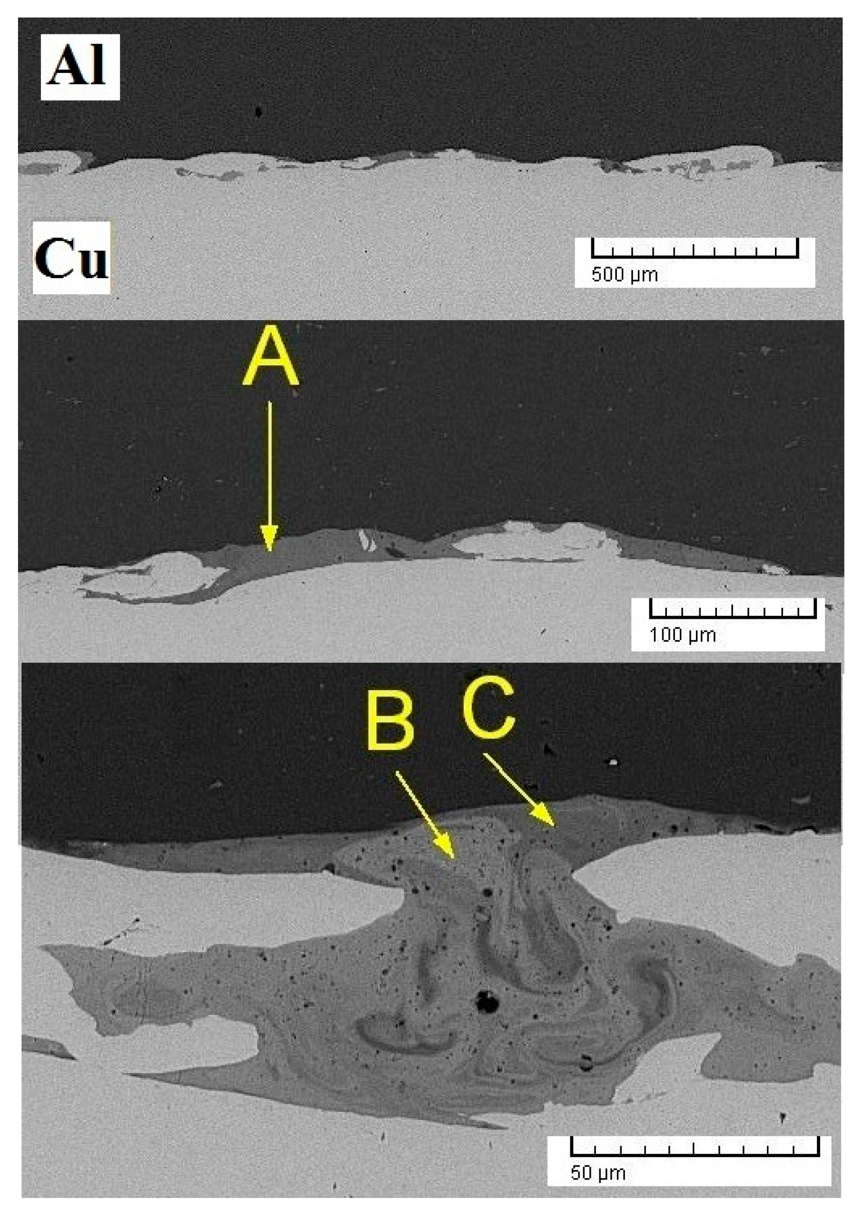
Figure 8 shows the SEM micrograph of the specimen S3. Based on the performed measurements on the sample S3, it is found that the thickness of the localized melting layer was about 40 µm, which was less than the formed intermediate layer in the specimen S2. This discrepancy was found to be a consequence of the stand-off distance decrement in the joint interface.
Table 3 shows the EDS analysis of the localized melted layer presented in Figure 8. As can be seen, the chemical composition of the localized melted layer in point A includes 70.10% Al, 19.01% Cu and 1.60% Mg (at.%), in point B includes 57.68% Al, 40.03% Cu, and 1.30% Mg (at.%), and in point C includes 76.25% Al, 22.08% Cu, and 1.60% Mg (at.%), thus proving the formation of Al2Cu, AlCu, and Al2Cu, respectively. Accordingly, in this case, again increasing the stand-off distance led to the formation of a thicker intermetallic layer. Likewise, increasing the copper percentage in the intermetallic layer makes its colour lighter and its brittleness higher.
3.2. Corrosion
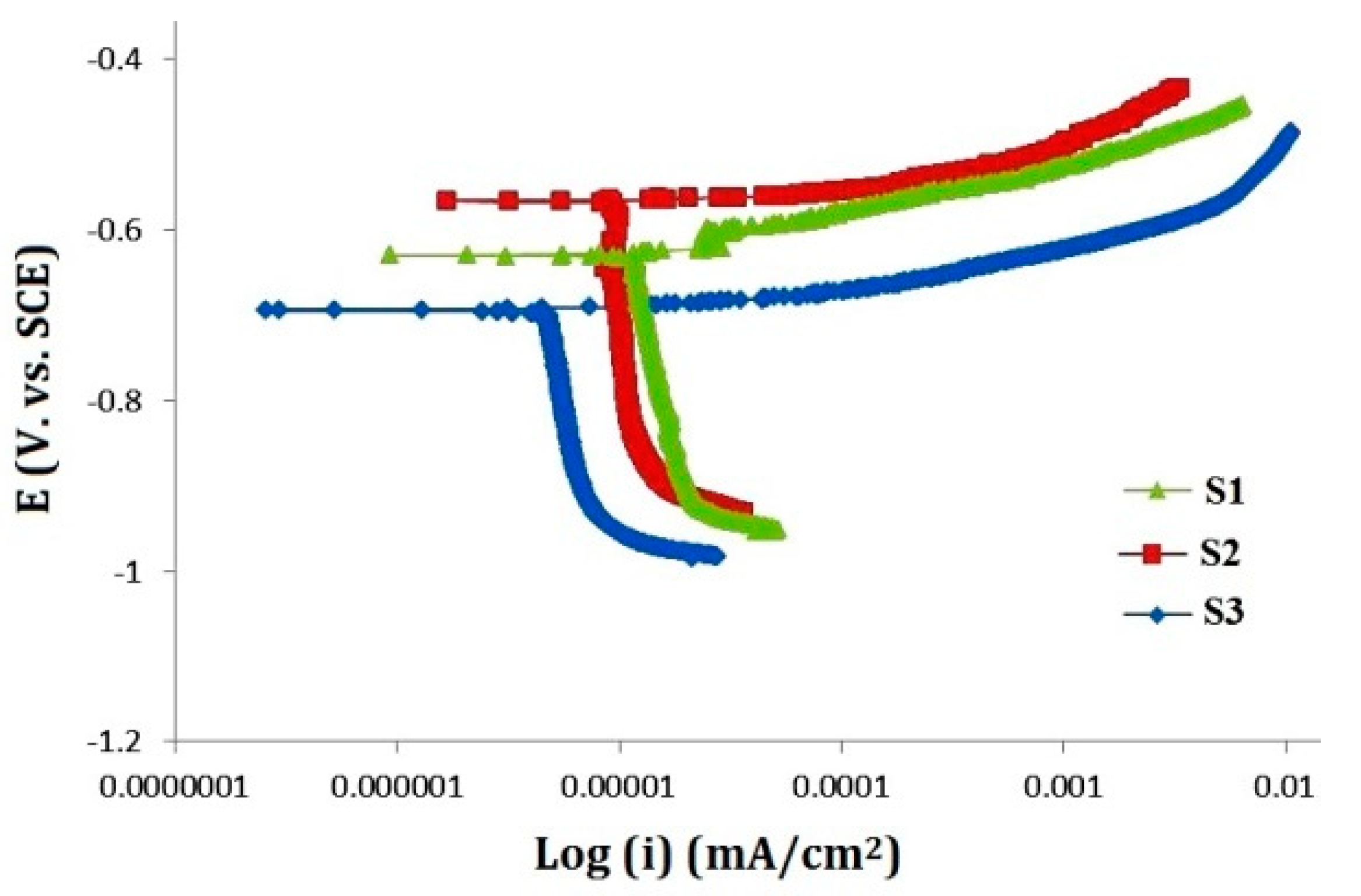
Figure 9 shows the polarization curves of explosively welded samples. Electrochemical parameters, such as corrosion potential (Ecorr), corrosion current density (icorr) (corrosion rate), and the gradients of anodic and cathodic Tafel obtained (using Tafel extrapolation method), have been extracted from these curves and reported in Table 4.
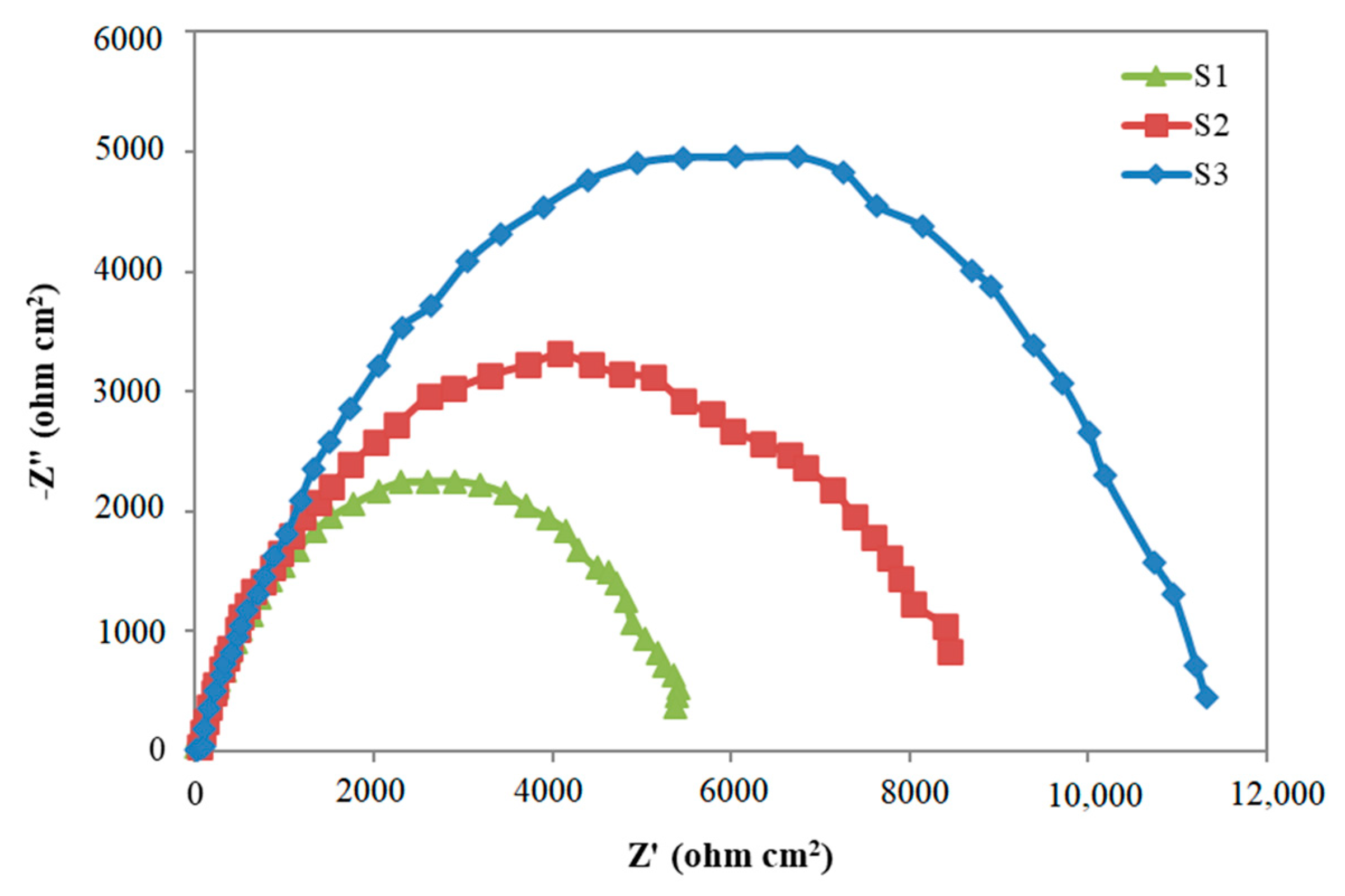
In general, the parallelism of the cathodic branches in Tafel plot (Figure 9) pointed that hydrogen emissions controlled by activation, while reduction of H+ ions on the surface of samples did not affect significantly by welding operations. Configurations of anode branches are different in Figure 9, and various parameters of explosive welding affected them. The results of Table 4 showed that by increasing the stand-off distance, the potential of corrosion and the corrosion current density increases from −691 to −624 mV, 4.49 to 15.80 µA·cm−2, respectively. This increase plausibly resulted from an increase in the thickness of the melting layer, which shows potential to increase the corrosion current density, mainly because of an increase in the ratio of cathodic to anodic areas [7]. In other words, higher stand-off distances between substrate and flying plate result in finer grains due to the severer explosive collision. Moreover, at higher stand-off distances, the quantity of the non-conductive intermetallic phases increases that could reduce the probable intergranular corrosion (IGC) originated from grain boundaries accumulation. Electrochemical impedance spectroscopy (EIS) was executed to study the created surface layer on samples in corrosive media. Nyquist diagrams related to explosive welding samples have shown in Figure 10. EIS data through the equivalent circuit, which are shown in Figure 10, were adequately validated with the experimental results presented in Table 5.
Figure 10 shows that the impedance loops obtained in the Nyquist curve have slightly crushed down as compared to a full half-circle, and this phenomenon is known as a sagging effect. In general, the deviation from the full half-circle could be attributed to the frequency dispersion, surface heterogeneities, and mass transfer resistance. This difference has justified by the non-ideal behaviour of the double layer as a capacitor. Accurate conformity could achieve by extension of relaxation times and dominance on the plausible non-uniformities in the micro- or nano-surfaces such as roughness, porous layers, impurities, absorption of inhibitors, penetration, etc. It is essential to use a constant phase element (CPE) instead of the non-ideal capacitor behaviour for double-layered. The impedance of a constant phase element could be calculated by the following equation [36]:
where Y0 is the relativistic factor (admittance) and n is non-uniformity coefficient of surface (phase difference). So, greater n implies on more uniformity of the welding intersection. For n = 0, 1, and −1, CPE shows conclusive resistive, decisive capacitive, and definitive inductive behaviour, respectively.
In this study, the diameter of the Nyquist curves (Figure 10) is considered as the polarization resistance (RP). In other words, the only available capacitive loops are related to the charge transfer resistance between the metal and outer Helmholtz layer (OHP). These observations indicate that the corrosion behaviour was under control through the charge transfer process. Dai and Qin et al. argued that the radius of the capacitor arc in the Nyquist plot implies the ability of the solution ions to cross through the passive layer and reach to the metal electrode. Hence, the larger radius of the capacitor results in lower corrosion tendency [37,38].
Using an equivalent circuit and presenting an appropriate model for the metal/solution intersection, the electrical double layer could adequately justify. Electrical equivalent circuit corresponding to the samples in the solution would measure as reported in the literature [36]. In the presence of inhibitors, polarization resistance (Rp), could be affected by the synergy of charge transfer resistance (Rct), the resistance of inhibiting layer on the metal surface (Rf), particles and obstacles (inhibitor molecules, corrosion products, etc.) accumulated at the metal/solution intersection (Ra), and resistance of diffusion layer (Rd) (Rp = Rct + Rf + Ra + Rd) [36].
Double-layered capacity (Cdl) can be calculated through the following equation:
where, is the maximum imaginary impedance component.
According to Table 5, sample S3 has the highest corrosion resistance, amounting to 12,000 (Ω·cm2), while sample S2 had lower stand-off distance and polarization resistance of 9000 (Ω·cm2). In the meantime, the S1 specimen with 6000 (Ω·cm2) had the lowest amount of polarization resistance. This might be caused by the creation of a high thickness of localized melting after an increase in the stand-off distance and the slope of the concentration potential due to changes in the localized melting layer. In addition, the corrosion current in the sample with a stand-off distance of 2.5 mm was the highest and decreased the load transfer resistance. Comparing the samples with the various stand-off distances (when the explosive charge was constant), it can be concluded that the highest load transfer resistance is related to the sample with stand-off distance of 1.5 mm, which is the lowest stand-off distance.
4. Conclusions
(1) According to OM results, the sample by stand-off distance of 2.5 mm (highest stand-off distance) had the maximum thickness of local melting. As the stand-off distance decreases, the thickness of the local melting layer decreases and the joint interface is smoother. Meanwhile, the layers near the welding intersection were more affected by the severe encounter and had the finest grains.
(2) Comparing SEM results and the EDS analysis token from intermediate layers revealed that the distribution of the chemical composition is not the same throughout the joint interface, and element separation at the intersection of the explosive joint was decreased by a reduction in stand-off distance.
(3) In the melted zone, the solid solution, as well as precipitates of different intermetallic phases, can be observed. Formation of these brittle intermetallic phases in the local melting layer is because of the explosive collision and mixing. It was found that the solidification contraction and intermetallic formation in the localized melting region resulted in crack formation.
(4) As the stand-off distance increases, the potential of corrosion changes due to changes in the concentration in the local melting layer as well as changes in the thickness of the layer.
(5) As the stand-off distance increases, the kinetic energy of the collision, the plastic deformation, and the thickness of the local melting layer increase in the joint interface, thus increasing the corrosion rate.
Author Contributions
M.R.J.: conceptualization, methodology, formal analysis, data curation, writing—original draft preparation. A.S.: writing—review and editing, supervision. G.K.: conceptualization, investigation, writing—review and editing. M.K.G.S.: software, validation, visualization. All authors have read and agreed to the published version of the manuscript.
Funding
This research received no external funding.
Acknowledgments
The authors gratefully acknowledge the provision of specimen fabrication facilities by WorldTech Scientific Research Center (WT-SRC).
Conflicts of Interest
The authors declare no conflict of interest.
References
- Prażmowski, M.; Rozumek, D.; Paul, H. Static and fatigue tests of bimetal Zr-steel made by explosive welding. Eng. Fail. Anal. 2017, 75, 71–81. [Google Scholar] [CrossRef]
- Kwiecień, M.; Majta, J.; Dziedzic, D. Shear deformation and failure of explosive welded Inconel-microalloyed steels bimetals. Arch. Civ. Mech. Eng. 2014, 14, 32–39. [Google Scholar] [CrossRef]
- Lysak, V.I.; Kuzmin, S.V. Lower boundary in metal explosive welding. Evol. Ideas J. Mater. Process. Technol. 2012, 212, 150–156. [Google Scholar] [CrossRef]
- Ning, J.; Zhang, L.-J.; Xie, M.-X.; Yang, H.-X.; Yin, X.-Q.; Zhang, J.-X. Microstructure and property inhomogeneity investigations of bonded Zr/Ti/steel trimetallic sheet fabricated by explosive welding. J. Alloy. Compd. 2017, 698, 835–851. [Google Scholar] [CrossRef]
- Benák, M.; Turňa, M.; Ožvold, M.; Nesvadba, P.; Lokaj, J.; Čaplovič, L.; KOVÁČ, F.; Stoyka, V. Study of Al-austenitic steel boundary formed by explosion welding. In METAL 2010: 19 Mezinárodní Konference Metalurgie a Materiálů; Tanger: Roznov pod Radhostem, Czech Republic, 2010; pp. 18–20. [Google Scholar]
- Saboori, A.; Moheimani, S.K.; Pavese, M.; Badini, C.; Fino, P. New nanocomposite materials with improved mechanical strength and tailored coefficient of thermal expansion for electro-packaging applications. Metals 2017, 7, 536. [Google Scholar] [CrossRef] [Green Version]
- Kengkla, N.; Tareelap, N. Role of Intermetallic Compound on Corrosion of Aluminium/Steel Transition Joint Used in Naval Applications. In Proceedings of the 1st Mae Fah Luang University International Conference 2012 (MFUIC2012) on the Future Challenges Towards ASEAN, Chiang Rai, Thailand, 29–30 November 2012. [Google Scholar]
- Mudali, U.K.; Rao, B.A.; Shanmugam, K.; Natarajan, R.; Raj, B. Corrosion and microstructural aspects of dissimilar joints of titanium and type 304L stainless steel. J. Nucl. Mater. 2003, 321, 40–48. [Google Scholar] [CrossRef]
- Acarer, M. Electrical, corrosion, and mechanical properties of aluminum-copper joints produced by explosive welding. J. Mater. Eng. Perform. 2012, 21, 2375–2379. [Google Scholar] [CrossRef]
- Kahraman, N.; Gülenç, B.; Findik, F. Joining of titanium/stainless steel by explosive welding and effect on interface. J. Mater. Process. Technol. 2005, 169, 127–133. [Google Scholar] [CrossRef]
- Kahraman, N.; Gulenc, B.; Findik, F. Corrosion and mechanical-microstructural aspects of dissimilar joints of Ti–6Al–4V and Al plates. Int. J. Impact Eng. 2007, 34, 1423–1432. [Google Scholar] [CrossRef]
- Rajani, H.Z.; Mousavi, S.A.; Sani, F.M. Comparison of corrosion behavior between fusion cladded and explosive cladded Inconel 625/plain carbon steel bimetal plates. Mater. Des. 2013, 43, 467–474. [Google Scholar] [CrossRef]
- Zhang, T.; Wang, W.; Zhang, W.; Wei, Y.; Cao, X.; Yan, Z.; Zhou, J. Microstructure evolution and mechanical properties of an AA6061/AZ31B alloy plate fabricated by explosive welding. J. Alloy. Compd. 2018, 735, 1759–1768. [Google Scholar] [CrossRef]
- Mróz, S.; Gontarz, A.; Drozdowski, K.; Bala, H.; Szota, P. Forging of Mg/Al bimetallic handle using explosive welded feedstock. Arch. Civ. Mech. Eng. 2018, 18, 401–412. [Google Scholar] [CrossRef]
- Boroński, D.; Kotyk, M.; Maćkowiak, P.; Śnieżek, L. Mechanical properties of explosively welded AA2519-AA1050-Ti6Al4V layered material at ambient and cryogenic conditions. Mater. Des. 2017, 133, 390–403. [Google Scholar] [CrossRef]
- Saboori, A.; Aversa, A.; Marchese, G.; Biamino, S.; Lombardi, M.; Fino, P. Application of Directed Energy Deposition-Based Additive Manufacturing in Repair. Appl. Sci. 2019, 9, 3316. [Google Scholar] [CrossRef] [Green Version]
- Fronczek, D.M.; Chulist, R.; Szulc, Z.; Wojewoda-Budka, J. Growth kinetics of TiAl3 phase in annealed Al/Ti/Al explosively welded clads. Mater. Lett. 2017, 198, 160–163. [Google Scholar] [CrossRef]
- Bataev, I.A.; Ogneva, T.S.; Bataev, A.A.; Mali, V.I.; Esikov, M.A.; Lazurenko, D.V.; Guo, Y.; Junior, A.J. Explosively welded multilayer Ni–Al composites. Mater. Des. 2015, 88, 1082–1087. [Google Scholar] [CrossRef]
- Sherpa, B.B.; Upadhyay, A.; Kumar, S.; Mangla, V.; Kumar, P.D.; Agarwal, A. Examination of Joint Integrity in parallel plate configuration of explosive welded SS-Al combination. Mater. Today Proc. 2017, 4, 1260–1267. [Google Scholar] [CrossRef]
- Corigliano, P.; Crupi, V.; Guglielmino, E.; Mariano Sili, A. Full-field analysis of AL/FE explosive welded joints for shipbuilding applications. Mar. Struct. 2018, 57, 207–218. [Google Scholar] [CrossRef]
- Shiran, M.K.G.; Khalaj, G.; Pouraliakbar, H.; Jandaghi, M.; Bakhtiari, H.; Shirazi, M. Effects of heat treatment on the intermetallic compounds and mechanical properties of the stainless steel 321–aluminum 1230 explosive-welding interface. Int. J. Miner. Metall. Mater. 2017, 24, 1267–1277. [Google Scholar] [CrossRef]
- Shiran, M.K.G.; Khalaj, G.; Pouraliakbar, H.; Jandaghi, M.R.; Dehnavi, A.S.; Bakhtiari, H. Multilayer Cu/Al/Cu explosive welded joints: Characterizing heat treatment effect on the interface microstructure and mechanical properties. J. Manuf. Process. 2018, 35, 657–663. [Google Scholar] [CrossRef]
- Carvalho, G.H.S.F.L.; Mendes, R.; Leal, R.M.; Galvão, I.; Loureiro, A. Effect of the flyer material on the interface phenomena in aluminium and copper explosive welds. Mater. Des. 2017, 122, 172–183. [Google Scholar] [CrossRef]
- Kaya, Y. Investigation of Copper-Aluminium Composite Materials Produced by Explosive Welding. Metals 2018, 8, 780. [Google Scholar] [CrossRef] [Green Version]
- Shiran, M.R.K.G.; Bakhtiari, H.; Mousavi, S.A.A.A.; Khalaj, G.; Mirhashemi, S.M. Effect of stand-off distance on the mechanical and metallurgical properties of explosively bonded 321 austenitic stainless steel-1230 aluminum alloy tubes. Mater. Res. 2017, 20, 291–302. [Google Scholar] [CrossRef] [Green Version]
- Mousavi, S.A.; Sartangi, P.F. Experimental investigation of explosive welding of cp-titanium/AISI 304 stainless steel. Mater. Des. 2009, 30, 459–468. [Google Scholar] [CrossRef]
- Chulist, R.; Fronczek, D.M.; Szulc, Z.; Wojewoda-Budka, J. Texture transformations near the bonding zones of the three-layer Al/Ti/Al explosively welded clads. Mater. Charact. 2017, 129, 242–246. [Google Scholar] [CrossRef]
- Fronczek, D.M.; Wojewoda-Budka, J.; Chulist, R.; Sypien, A.; Korneva, A.; Szulc, Z.; Schell, N.; Zieba, P. Structural properties of Ti/Al clads manufactured by explosive welding and annealing. Mater. Des. 2016, 91, 80–89. [Google Scholar] [CrossRef]
- Chu, Q.; Zhang, M.; Li, J.; Yan, C. Experimental and numerical investigation of microstructure and mechanical behavior of titanium/steel interfaces prepared by explosive welding. Mater. Sci. Eng. A 2017, 689, 323–331. [Google Scholar] [CrossRef]
- Azad, M.R.; Ghasemi, A.; Pouraliakbar, H.; Jandaghi, M.R. On the Al/Cu Dissimilar Joints Produced Through Simple Cold Compression. Trans. Indian Inst. Met. 2015, 68, 991–998. [Google Scholar] [CrossRef]
- Loureiro, A.; Mendes, R.; Ribeiro, J.B.; Leal, R.M.; Galvão, I. Effect of explosive mixture on quality of explosive welds of copper to aluminium. Mater. Des. 2016, 95, 256–267. [Google Scholar] [CrossRef]
- Wołczyński, W.S.; Okane, T.; Senderowski, C.; Zasada, D.; Kania, B.; Janczak-Rusch, J. Thermodynamic Justification for the Ni/Al/Ni Joint Formation by Diffusion Brazing. Int. J. Thermodyn. 2011, 14, 97–105. [Google Scholar] [CrossRef]
- Wołczyński, W.S.; Okane, T.; Senderowski, C.; Kania, B.; Zasada, D.; Janczak-Rusch, J. Meta-Stable Conditions of Diffusion Brazing. Arch. Metall. Mater. 2011, 56, 311–323. [Google Scholar] [CrossRef] [Green Version]
- Wołczyński, W.S. Development of the Jackson and Hunt Theory for Rapid Eutectic Growth. Arch. Metall. Mater. 2018, 63, 65–72. [Google Scholar]
- Wołczyński, W.S. Back-Diffusion in Crystal Growth. Eutectics. Arch. Metall. Mater. 2015, 60, 2403–2407. [Google Scholar] [CrossRef]
- Jorcin, J.-B.; Orazem, M.E.; Pébère, N.; Tribollet, B. CPE analysis by local electrochemical impedance spectroscopy. Electrochim. Acta 2006, 51, 1473–1479. [Google Scholar] [CrossRef]
- Dai, N.; Zhang, L.-C.; Zhang, J.; Chen, Q.; Wu, M. Corrosion Behaviour of Selective Laser Melted Ti-6Al-4V Alloy in NaCl Solution. Corros. Sci. 2016, 102, 484–489. [Google Scholar] [CrossRef]
- Qin, P.; Liu, Y.; Sercombe, T.; Li, Y.; Zhang, C.; Cao, C.; Sun, H.; Zhang, L.-C. Improved corrosion resistance on selective laser melting produced Ti-5Cu alloy after heat treatment. ACS Biomater. Sci. Eng. 2018, 4, 2633–2642. [Google Scholar] [CrossRef]
Figure 1.
Schematic representation of explosive welding procedure [24].
Figure 1.
Schematic representation of explosive welding procedure [24].

Figure 2.
The microstructure of initially annealed Al (a) and Cu (b).

Figure 3.
OM micrographs showing the binding interface of (a) S1, (b) S2 and (c) S3 specimen.

Figure 4.
The microstructure of deformed zone around the intersection in the copper side (a), in the aluminium side (b), separated pieces of copper in Al side (c), refined Al grains in the interface (d) and interface conformation (e).
Figure 4.
The microstructure of deformed zone around the intersection in the copper side (a), in the aluminium side (b), separated pieces of copper in Al side (c), refined Al grains in the interface (d) and interface conformation (e).

Figure 5.
XRD pattern of welding interface in the specimen S1.

Figure 6.
Backscattered SEM images of the locally melted zone at the intersection of specimen S1.

Figure 7.
Backscattered SEM images of the locally melted zone at the intersection of the samples S2.
Figure 7.
Backscattered SEM images of the locally melted zone at the intersection of the samples S2.

Figure 8.
SEM images of the locally melted zone at the intersection of the samples S3.

Figure 9.
Potentiodynamic polarization curves of samples of the explosive welding.

Figure 10.
Impedance spectra on the Nyquist plot of explosively welded samples.


Table 1.
The chemical composition of the base and flying plates (wt.%).
| Elements | Balance | Sn | Zn | Si | Mg | Mn | Cr | Ti |
|---|---|---|---|---|---|---|---|---|
| Copper | Cu | 0.92 | 0.12 | - | - | - | - | - |
| Al 5083 | Al | 0.02 | 0.25 | 0.40 | 4.75 | 0.70 | 0.25 | 0.15 |
Table 2.
Regulatory characteristics of performed tests and the resulting interfaces.
| Test Number | Stand-Off Distance (mm) | Explosive Charge |
|---|---|---|
| S1 | 2.5 | 2.0 |
| S2 | 2.0 | 2.0 |
| S3 | 1.5 | 2.0 |
Table 3.
The EDS analysis of the localized melted layer presented in Figure 6, Figure 7 and Figure 8.
| %wt | S1-A | S1-B | S1-C | S2-A | S2-B | S2-C | S3-A | S3-B | S3-C |
|---|---|---|---|---|---|---|---|---|---|
| Mg | 1.75 | 1.06 | 1.56 | 3.09 | 0.00 | 1.31 | 1.60 | 1.30 | 1.68 |
| Al | 74.49 | 68.51 | 80.85 | 75.69 | 53.9 | 66.17 | 78.18 | 58.67 | 76.25 |
| Cu | 23.76 | 30.43 | 17.58 | 21.21 | 46.10 | 31.66 | 19.81 | 40.03 | 22.08 |
Table 4.
Electrochemical parameters obtained from potentiodynamic polarization curves obtained using explosive welding in 3.5% NaCl solution at ambient temperature.
Table 4.
Electrochemical parameters obtained from potentiodynamic polarization curves obtained using explosive welding in 3.5% NaCl solution at ambient temperature.
| Sample | icorr (µA·cm−2) | Ecorr (mV) | βa (mV·dec−1) | Βc (mV·dec−1) |
|---|---|---|---|---|
| S1 | 15.80 | −624 | 207 | 99 |
| S2 | 9.57 | −569 | 202 | 120 |
| S3 | 4.49 | −691 | 215 | 73 |
Table 5.
EIS data obtained using explosive welding in 3.5% NaCl solution at ambient temperature.
| Sample | Rs (Ω) | Rp (Ωcm2) | Cdl-T (µF·cm−2) | Cdl-P (µF·cm−2) |
|---|---|---|---|---|
| S1 | 8 | 6000 | 2.20 × 10⁻⁵ | 0.65 |
| S2 | 10 | 9000 | 2.10× 10⁻⁵ | 0.75 |
| S3 | 12 | 12,000 | 2.00× 10⁻⁵ | 0.85 |
© 2020 by the authors. Licensee MDPI, Basel, Switzerland. This article is an open access article distributed under the terms and conditions of the Creative Commons Attribution (CC BY) license (http://creativecommons.org/licenses/by/4.0/).
Share and Cite
MDPI and ACS Style
Jandaghi, M.R.; Saboori, A.; Khalaj, G.; Khanzadeh Ghareh Shiran, M. Microstructural Evolutions and its Impact on the Corrosion Behaviour of Explosively Welded Al/Cu Bimetal. Metals 2020, 10, 634. https://doi.org/10.3390/met10050634
AMA Style
Jandaghi MR, Saboori A, Khalaj G, Khanzadeh Ghareh Shiran M. Microstructural Evolutions and its Impact on the Corrosion Behaviour of Explosively Welded Al/Cu Bimetal. Metals. 2020; 10(5):634. https://doi.org/10.3390/met10050634
Chicago/Turabian StyleJandaghi, Mohammad Reza, Abdollah Saboori, Gholamreza Khalaj, and Mohammadreza Khanzadeh Ghareh Shiran. 2020. "Microstructural Evolutions and its Impact on the Corrosion Behaviour of Explosively Welded Al/Cu Bimetal" Metals 10, no. 5: 634. https://doi.org/10.3390/met10050634
Note that from the first issue of 2016, this journal uses article numbers instead of page numbers. See further details here.