A 2D Multiphase Model of Drop Behavior during Electroslag Remelting
by
 , ,
, ,
Jérémy Chaulet
1,2, 
Abdellah Kharicha
3,*,
Sylvain Charmond
2,
Bernard Dussoubs
1,
Stéphane Hans
2,
Menghuai Wu
4,
Andreas Ludwig
4 and
Alain Jardy
1 1
Institut Jean Lamour (UMR 7198 Université de Lorraine/CNRS), Campus Artem, 2 allée André Guinier-BP 50840, LabEx DAMAS, F-54011 Nancy CEDEX, France
2
Aubert & Duval, BP 1, F-63770 Les Ancizes, France
3
Christian Doppler Laboratory for Metallurgical Applications of MHD, Montanuniversitaet, Franz Josef-Straße 18, A-8700 Leoben, Austria
4
Chair of Simulation and Modeling of Metallurgical Processes, Montanuniversitaet, Franz Josef-Straße 18, A-8700 Leoben, Austria
*
Author to whom correspondence should be addressed.
Metals 2020, 10(4), 490; https://doi.org/10.3390/met10040490
Submission received: 16 March 2020
/
Revised: 1 April 2020
/
Accepted: 3 April 2020
/
Published: 8 April 2020
(This article belongs to the Special Issue Mathematical Modeling and Simulation in Ironmaking and Steelmaking)
Abstract
:Electroslag remelting is a process extensively used to produce metallic ingots with high quality standards. During the remelting operation, liquid metal droplets fall from the electrode through the liquid slag before entering the liquid pool of the secondary ingot. To better understand the process and help to optimize the operating condition choice, a 2D axisymmetric multiphase model of the slag domain has been developed using a two fluid Eulerian approach. During their fall, droplets hydrodynamic interactions are calculated thanks to an appropriate drag law. Influence of droplets on the electromagnetic field and on the slag hydrodynamics is discussed, as well as their heat exchange with the slag. Even with a small volume fraction, the droplets influence is noticeable. The present investigation shows that small droplets have a large influence on the slag hydrodynamics, due to a great momentum exchange. However heat transfer is more influenced by large drops, which are found to be relatively far from the thermal equilibrium with the slag phase.
1. Introduction
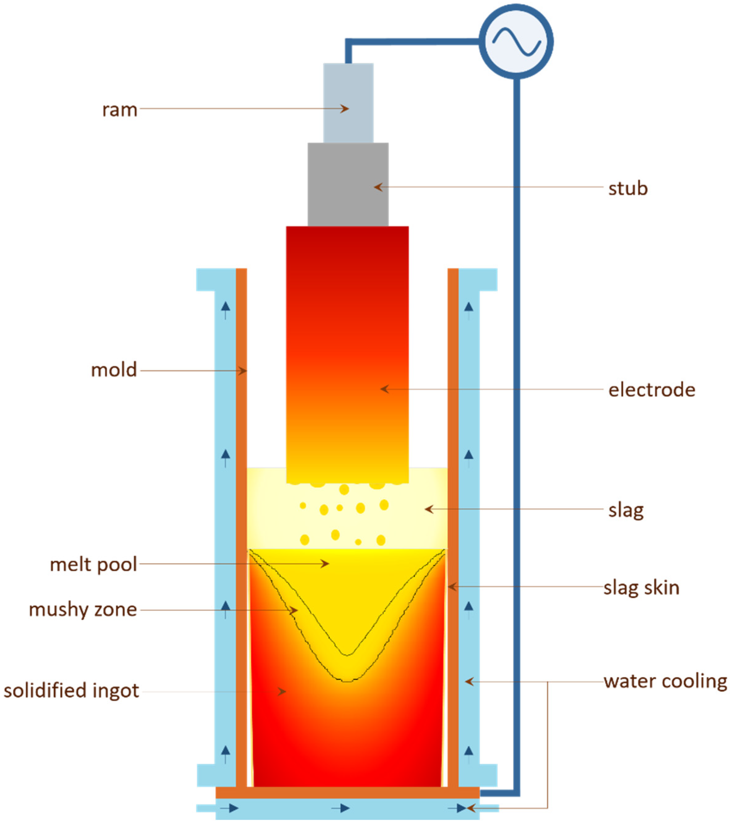
Electroslag remelting (ESR) is a leading process to produce alloys for applications requiring high metallurgical quality. For example, aeronautics, energy or tooling demand a reduced macro- and meso-segregation and a good inclusion cleanliness. These requirements may be achieved thanks to remelting operations. A schematic representation of the electroslag remelting process is presented in Figure 1. A primary ingot, also called the electrode, is immersed into a liquid slag. This slag is composed of calcium fluoride and various oxides such as lime, alumina or magnesia. Electric current is supplied to the process and is dissipated into Joule heating as it flows through the slag, since the latter is a highly resistive medium. Heat is transferred to the electrode, which then melts gradually, forming a liquid film underneath the electrode. From this liquid film, liquid metal drops form and fall through the slag. Liquid metal is collected into a copper mold cooled by a water circuit. The growing secondary ingot is constituted of a solid part, a mushy zone, and a melt pool where the liquid metal drops are falling. A comprehensive description of the process has been made in particular by Hoyle [1].
Remelted ingot quality is linked to the solidification conditions, such as the local solidification time for example [2]. Another way to assess ingot quality is to examine the liquid pool shape and depth. Melt pool profile depends on the magnitude and distribution of heat transfer at the boundaries of the ingot. Heat is extracted at the bottom and at the lateral bounds—the copper mold being continuously cooled—while heat is supplied through the slag/ingot interface. Previous work showed that drops are the main enthalpy carrier, whereas conductive transfer at the slag/liquid pool interface represents less than 20% of the total heat input to the ingot [2,3].
Studying the influence of operating conditions on the ingot quality using a trial and error approach is hindered by the cost of such remelting operations, the complexity of the process and the intricacy of in-situ measurements. Then, in order to better understand the energy transfer during the electroslag remelting, numerical modeling became the tool-of-choice. The first 2D models based on the resolution of coupled transfers were monophasic and covered only some parts of the process [4,5,6,7], and then were improved to comprehensively describe the entire process [8,9,10,11].
Later, the development of 3D multiphasic models [12,13,14,15,16,17] made the study of the liquid metal drop formation and behavior achievable. Such models are then very useful to better understand the mass and energy transfers; however their very high computational cost prevents a wide application.
A few 2D diphasic models of the electroslag remelting process were developed, based on the volume of fluid (VOF) method to track the interfaces between slag and metal [18,19,20,21,22]. Considering the drop behavior, such a 2D approach can be used if only one droplet is formed toward the axis, which can be the case for laboratory scale ESR. Thereby, these models are unsuitable to study industrial geometries as multiple droplets are formed under the electrode [12].
Whereas a 2D axisymmetric approach is adequate to model ingot solidification [24], an accurate simulation of drop behavior requires a three-dimensional model. Nonetheless, implementing an extensive description of drop behavior within a comprehensive 2D axisymmetric model of the electroslag remelting process could be a great improvement. Characterizing the enthalpy content of the liquid metal drops, their distribution and velocities, the computation of energy transfers to the melt pool would be more accurate, and thus the assessment of the expected final ingot quality would be better.
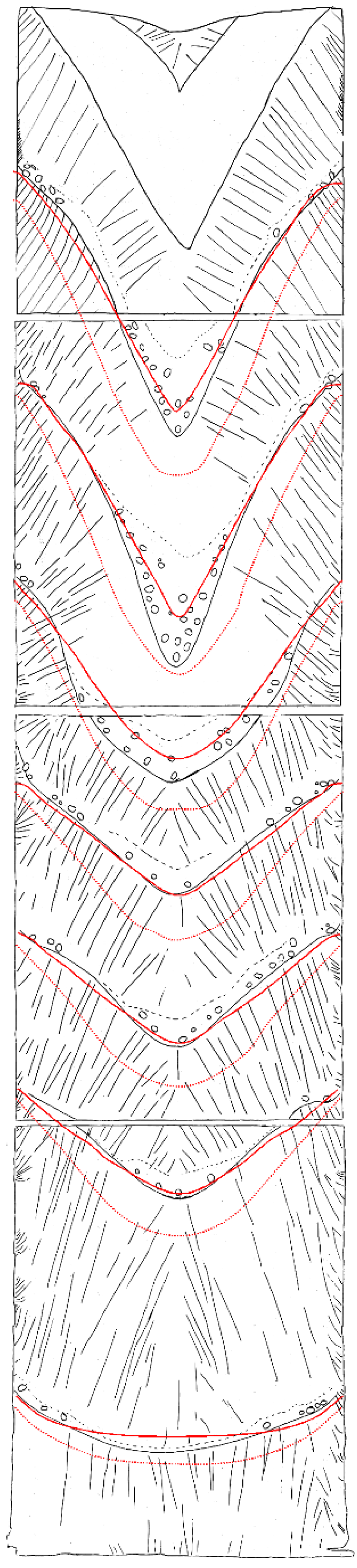
For instance, Weber et al. [8] compared the liquid pool profiles simulated using their comprehensive 2D axisymmetric model to those obtained from an industrial Ni-based alloy remelted ingot. Two main stages composed this experiment: the first half of the electrode was remelted using a low melt rate and a low current, and then a higher melt rate was achieved using a higher electric current. Operating conditions are given more in details in the original publication.
Figure 2 reproduces the ingot structure, with seven pool profiles marked by the addition of nickel balls. The calculated pool profiles are overlaid: dashed lines locate the liquidus isotherms and dotted lines the solidus. The first four calculated pool profiles are in excellent agreement with the observation. The next ones are in fairly good agreement, but the shape is not entirely complied with. As the melt rate is higher during this part of the remelting, droplets may have more influence on heat distribution and hydrodynamics. An improved description of energy transfer, especially by the drops contribution to the melt pool, could make the simulation more accurate.
With this in mind, the present work—inspired by a previous study made by Kharicha et al. [25]—addresses the development of a two-fluid average model in a 2D axisymmetric frame. This model is then used to study the influence of drop fall on hydrodynamics and heat transfer during electroslag remelting.
2. Model Description
A 2D axisymmetric thermo-magnetohydrodynamic model has been developed at Montanuniversitaet (Leoben, Austria) and at the Institut Jean Lamour (Nancy, France), in close collaboration with Aubert & Duval company (Les Ancizes, France). It is based on a two-fluid Eulerian approach to model the diphasic flow. Liquid slag constitutes the continuous phase, through which falling liquid metal droplets are dispersed.
This section presents the constitutive equations of the model. Subscript s refers to the continuous phase (the slag), m to the dispersed phase (the liquid metal) and mixt to the mixture data.
2.1. Electromagnetism
Electromagnetic phenomena are of great importance in the electroslag remelting process since the heat source is created by an electric current flowing through the slag. The four Maxwell equations, which govern these electromagnetic phenomena, can be reduced to a single one when the displacement current is negligible: the induction equation. Assuming that the process is axisymmetric, the electromagnetic field B is purely azimuthal. Therefore, using cylindrical coordinates (r, θ, z), the induction equation reduces to Equation (1):
where μ0 is the magnetic permeability of free space, and σmixt is the mixture electrical conductivity per cell.
This equivalent conductivity per cell σmixt depends on the volume fraction of liquid metal αm. It is here calculated using the Equation (2), derived by Maxwell assuming small spheres dispersed in a medium of distinct electrical conductivity [26]:
where σs and σm are the electrical conductivities of the liquid slag and liquid metal.
To account for the time periodicity of the alternating current supplied to the process, the phasor notation is used. For instance, the phasor of the electromagnetic induction is given by Equation (3).
where j2 = −1, ω is the pulsation and φ the phase.
Once the magnetic field has been computed, electric current density J is determined using Ampère’s circuital law (4).
The power generated by Joule Heating and the Lorentz forces are computed using Equations (5) and (6). They are accounted for as source terms respectively in the heat transfer and the momentum equations.
Following Leenov and Kolin’s discussion of the electromagnetokinetic effect [27], Lorentz Forces (Equation (6)) acting on the drops are multiplied by 3/2. This coefficient accounts for a MHD force due to the pressure gradient created in the fluid by the interaction of the electric current and the magnetic field. In the slag phase, and where the liquid metal does not form drops, Equation (6) remains unchanged.
2.2. Continuity and Phase Fraction Equations
The continuity equation for the dispersed phase (7) is solved to compute the volume fraction αm of liquid metal. υm is the metal velocity vector.
The slag volume fraction αs is then deduced using the relation αs + αm = 1, which is a consequence of the mixture continuity Equation (8).
2.3. Hydrodynamics
One set of momentum equations is solved per phase. The two phases are considered as an interpenetrating continuum and share a unique pressure field . The momentum equation for the continuous phase (the slag) is written below (Equation (9)). A similar equation is solved for the liquid metal dispersed phase.
The shear rate tensor , or viscous stress tensor, accounts for the diffusive momentum transfer. The buoyancy force FBo follows the Boussinesq approximation. The source term Rms represents the interphase momentum exchange, and is developed according to Equation (10).
is the drop Reynolds number, μ the dynamic viscosity, Ai is the interfacial area concentration, τ is the drop relaxation time constant, and CD is the drag coefficient.
During the electroslag remelting operation, droplets are formed within a wide size range, typically lying between 1 and 10 mm [28]. However, in the present study, the liquid metal dispersed phase is characterized by a unique drop diameter dp.
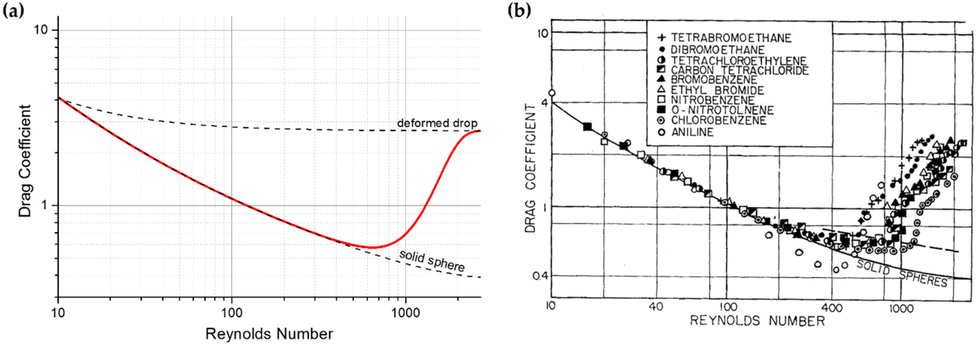
At an intermediate Reynolds number, drop behavior can deviate from the one of a rigid sphere. As shown by the experiments performed by Hu and Kintner [29], when the drop diameter is increased, the drag coefficient raises from the standard drag curve. This may be the result of internal fluid circulation inside the drop, or interfacial oscillations.
From these results and Loth’s analysis [30], an accurate drag function is proposed, based on the evaluation of an increment of the drag coefficient compared to the ideal solid sphere case, and bounded by the case of a highly deformable drop.
The drag coefficient is thus given by Equation (11) [30]:
is the Weber adimensional number , where γ is the slag/metal interfacial tension. represents the drag coefficient of an ideal sphere, and is estimated thanks to Clift and Gauvin (Equation (12)) [31]:
is the drag coefficient of a strongly deformed drop, for which the result of Davies and Taylor modified by Moore is used (Equation (13)) [31]:
As no fit for the drag increment has been found for drops, the expression given by Loth for bubbles is chosen (Equation (14)) [30]:
2.4. Heat Transfer
One enthalpy h transport equation is solved for each phase. Convection and conduction are taken into account. The enthalpy equation solved for the slag phase is given by Equation (15):
where λ is the thermal conductivity.
Qms represents the interphase heat exchange, and is computed as stated in Equation (16):
Interfacial heat transfer coefficient is estimated from Ranz and Marshall’s correlation (Equation (17)):
where is the Nusselt number and is the slag Prandtl number.
2.5. Calculation Domain, Boundary Conditions and Resolution
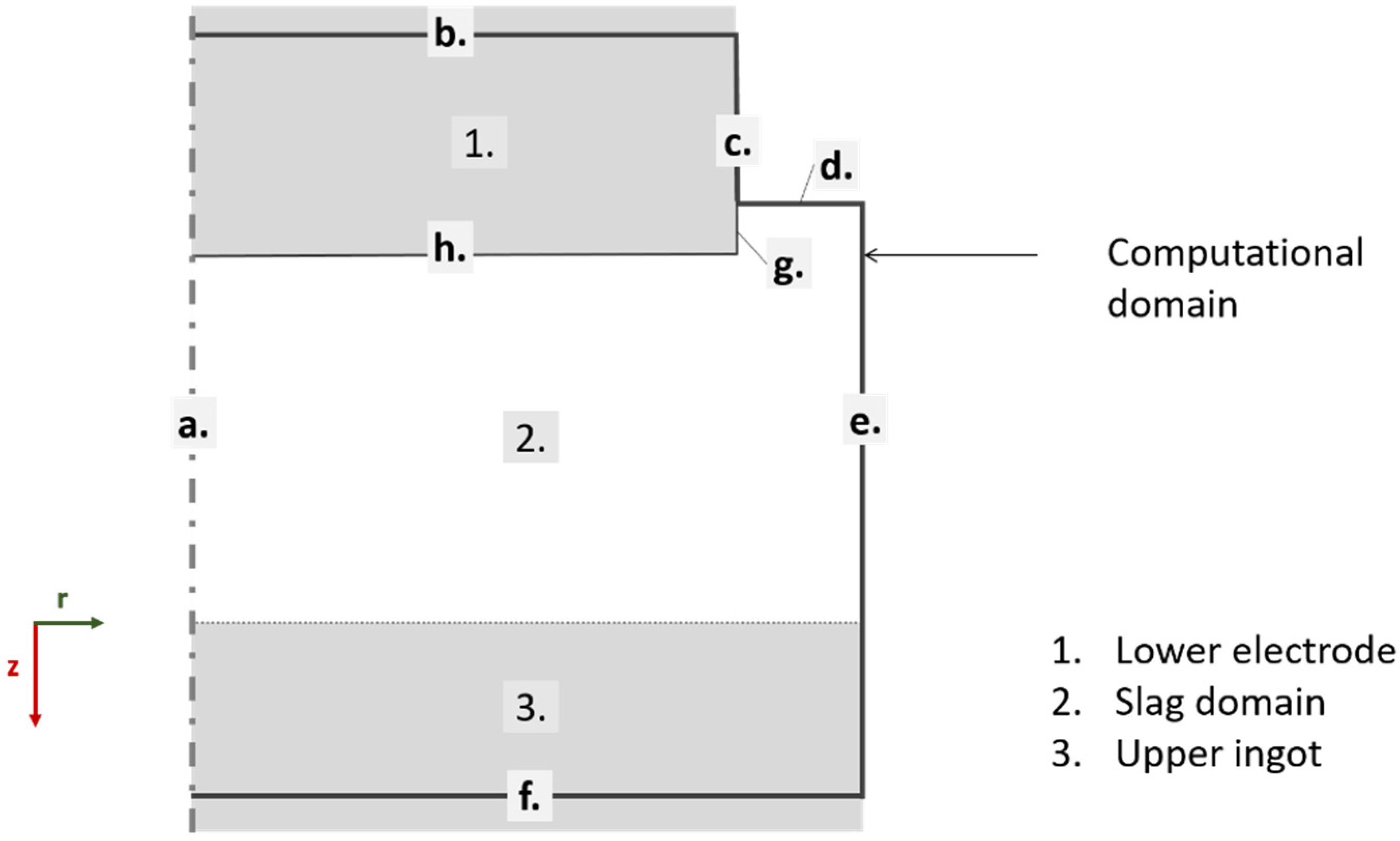
The computational domain is schematically shown in Figure 4, while the process dimensions and operating conditions for the industrial-sized reference case studied are given in Table 1. The domain covers the whole slag bath and includes the lower part of the electrode and the upper part of the ingot. The immersed tip is considered flat and does not suffer any morphology change during the simulation. Solidification of the ingot is not considered.
Slag–ingot interface is not explicitly represented: the slag and upper ingot are within the same resolution zone, where the two fluids (slag and metal) form a continuum. This interface is then located by means of the liquid metal volume fraction field.
A source of liquid metal drop, related to the melt rate, is distributed homogeneously under the horizontal electrode–slag interface.
Boundary conditions are summarized in Table 2. The radiative heat loss is calculated using Stefan–Boltzmann law, assuming an emissivity of 0.9 and an external temperature of 1000 K. Regarding the electromagnetic boundary conditions at c., d. and e., Ampère’s circuital law (18) is applied:
The CFD commercial software ANSYS Fluent is used to solve the coupled transfers of momentum and enthalpy. Electromagnetic field is calculated using User Defined Functions (UDF) written in C language and loaded with ANSYS Fluent solver. The multiphase coupled scheme is used for pressure-velocity coupling. First order upwind is used for spatial discretization of the flow. For time discretization, the implicit scheme is applied. The 2D mesh contains 28,845 quadrilateral cells, among them 25,545 covering the zones 2 and 3 (see Figure 4). A pseudo steady state is obtained; results are then time-averaged during 40 s. This represents around 60 h of computation, using a time step of 5 × 10⁻⁴ s, with a 3.30 GHz CPU.
2.6. Material Properties
Physical properties of the materials, needed as model input data, are presented in Table 3, along with their values in this study, corresponding to the remelting of a low-alloyed steel using a standard 70/15/15 type slag.
3. Results and Discussions
3.1. Drop Fall Influence
In this section, the model is applied to two cases. The first one does not consider the fall of liquid drops through the slag, in order to be similar to usual monophasic 2D axisymmetric simulations. For the second case, the fall of 5 mm drops through the slag is considered.
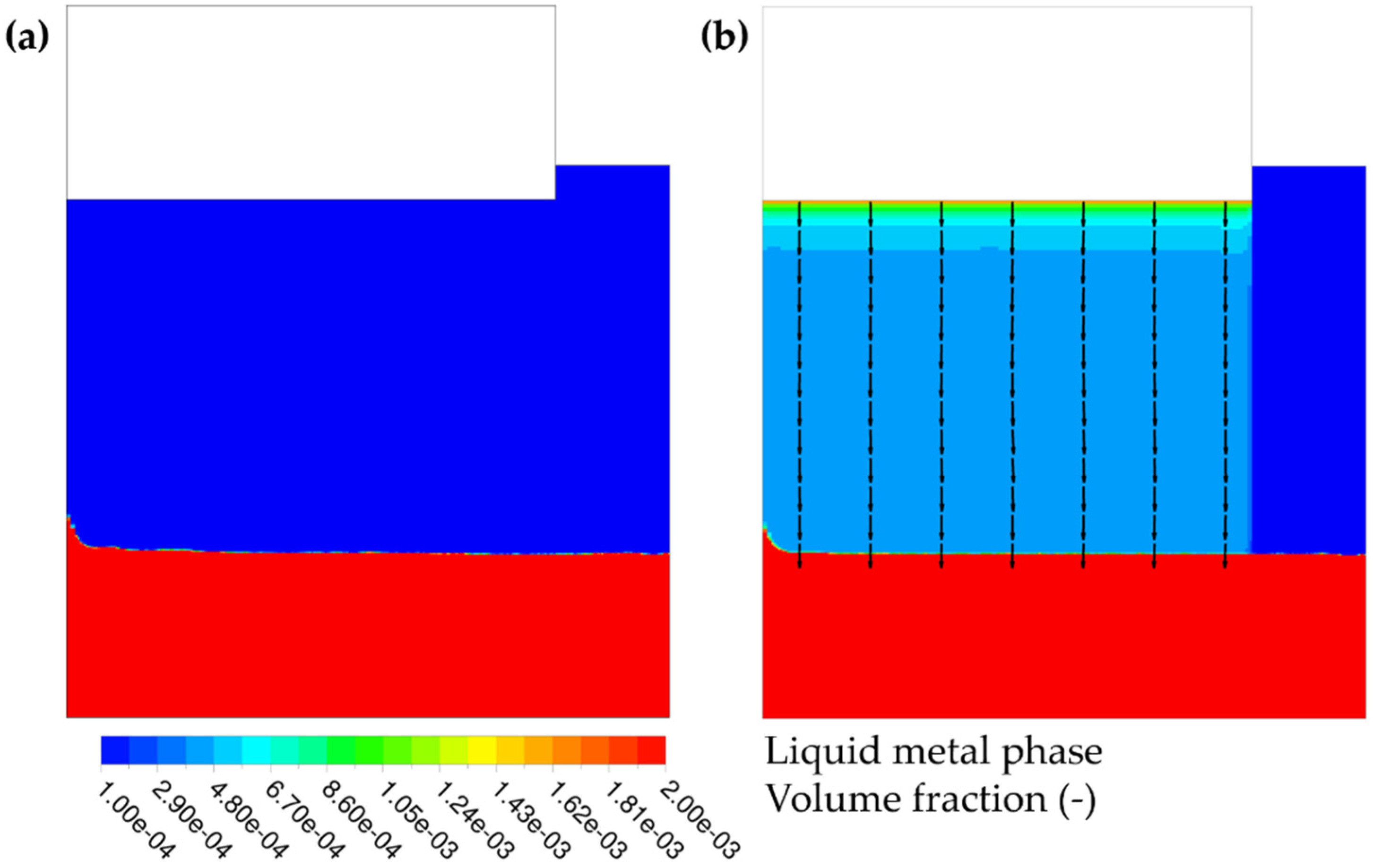
The time-averaged liquid metal volume fraction fields are plotted in Figure 5 for both cases. Liquid metal drop source is distributed evenly under the electrode. Within the slag, falling drops lead to small liquid metal volume fractions: around 5 × 10⁻⁴ in the zone where drop acceleration is negligible. Since the calculated drop terminal velocity is around 0.38 m·s−1, these 5 mm drops have a residence time of about 0.45 s, which explains the small volume fractions obtained.
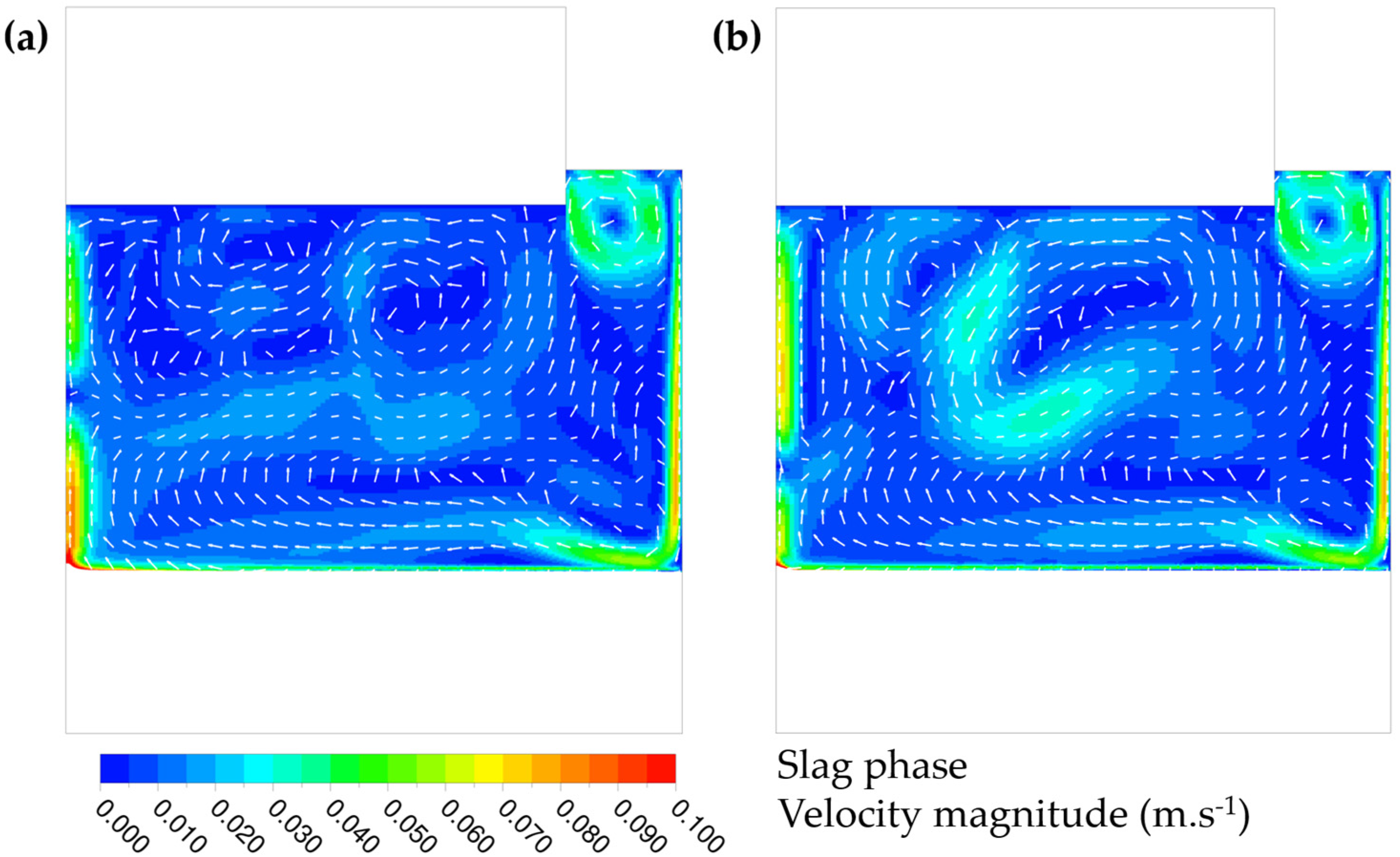
As reported by various studies using monophasic models [5,7,9], slag motion is driven by the combination of Lorentz forces and buoyancy. The thermal buoyant circulation is caused by the lateral cooling, and is seen as a clockwise motion on Figure 6a. The Lorentz forces, generated as the electric current flows through the slag, create a vortex under the electrode, and are visible as a counter-clockwise loop in Figure 6.
The fall of liquid metal droplets seems to amplify the electro-vortex under the electrode. Thermal loop driven by lateral cooling is obviously identical, as no drops are falling in this region. The smaller vortex driven by Lorentz forces in the annular zone remains also the same.
Regarding the electromagnetic field, no change is noticeable. Actually, equivalent electrical conductivity is very close to the slag one because of the low liquid metal volume fraction. For example, where the volume fraction is around 5 × 10⁻⁴, the average electrical conductivity calculated using Maxwell Equation (2) is 250.3 Ω−1·m−1, while the slag electrical conductivity is 250 Ω−1·m−1. Hence, current density is the same in both cases, and consequently, the slag experiences similar Lorentz forces. This is particularly noticeable on the small counter-clockwise loop in the annular zone.
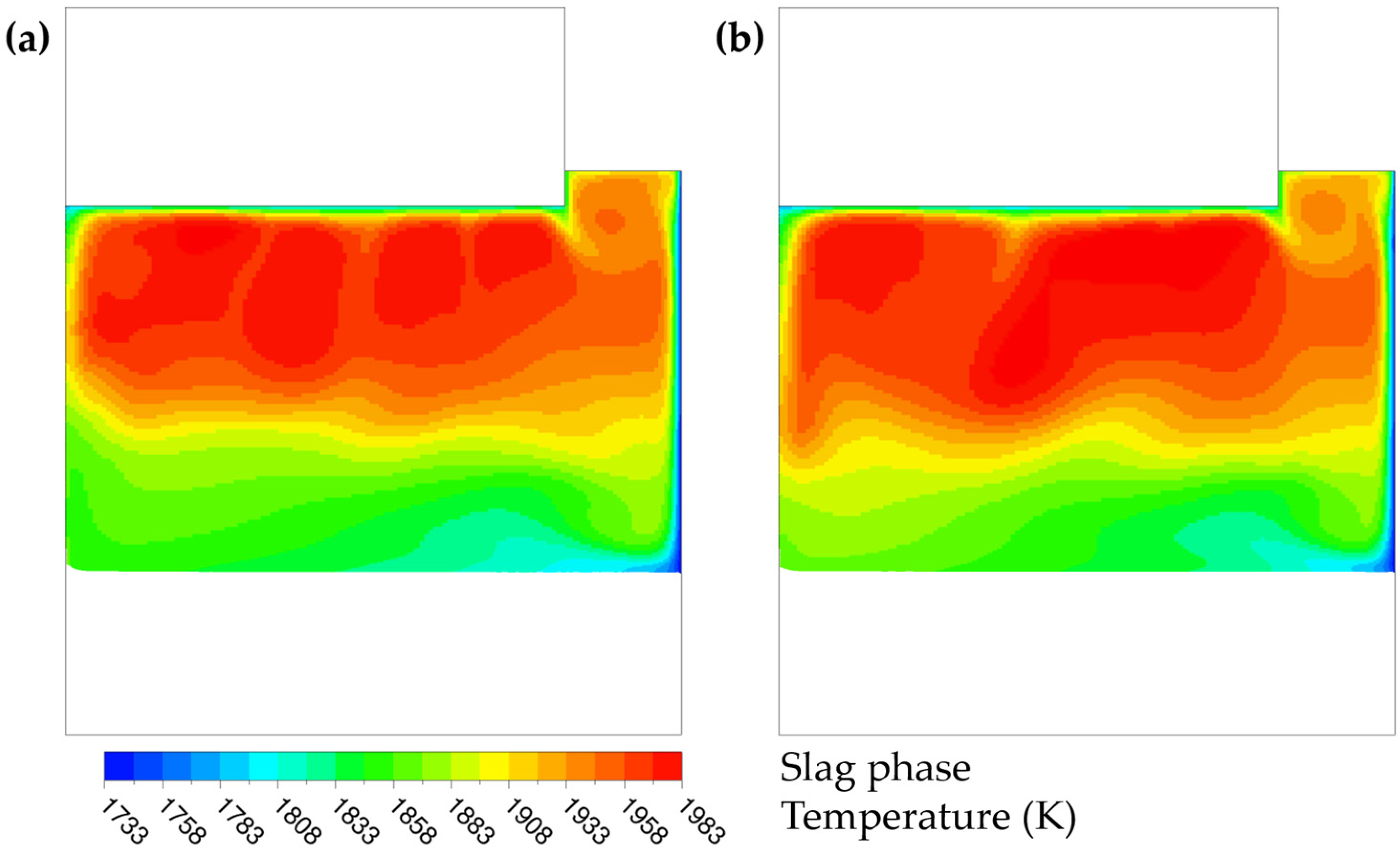
As illustrated in Figure 7, temperature distribution within the slag is quite similar in both cases, the hotter region is located underneath the electrode tip. For the case considering the drops fall, the hot zone is extended because of the wider electromagnetic recirculation loop.
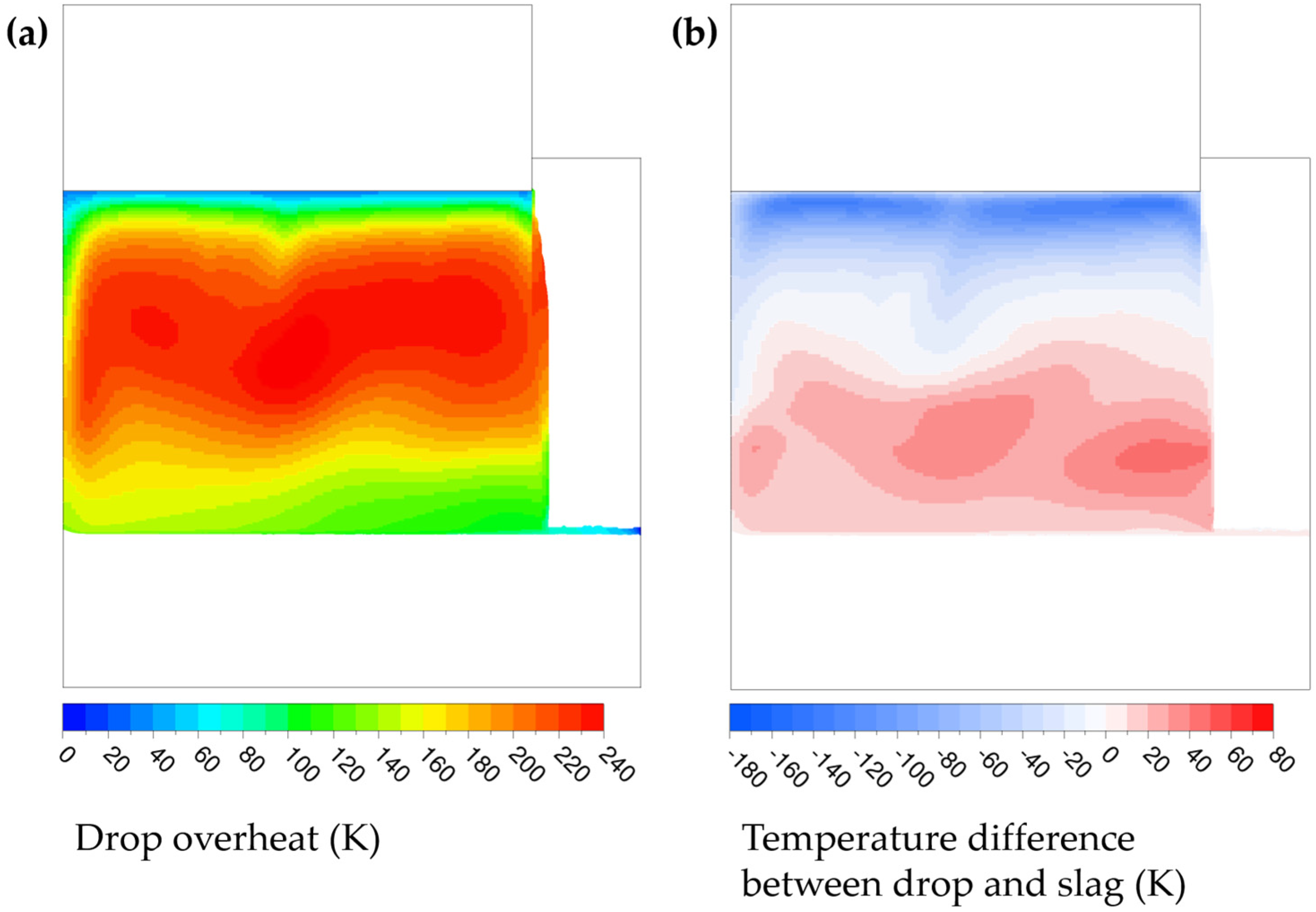
It is interesting to look at the temperature difference between slag and drop and the drop overheat fields, as shown in Figure 8. Drop overheat is defined by T − Tliquidus. The drops are first heated by the slag when they fall through the hotter region, and then are cooled as they reached the cooler bottom part of the slag cap. Finally, they are overheated by around 100 to 120 K when they enter the melt pool. One can also notice that drops of 5 mm and larger diameter are not in thermal equilibrium with the slag, as illustrated in Figure 8b. This represents a fairly new finding, as thermal equilibrium has been generally assumed throughout the literature.
3.2. Influence of Drop Diameter
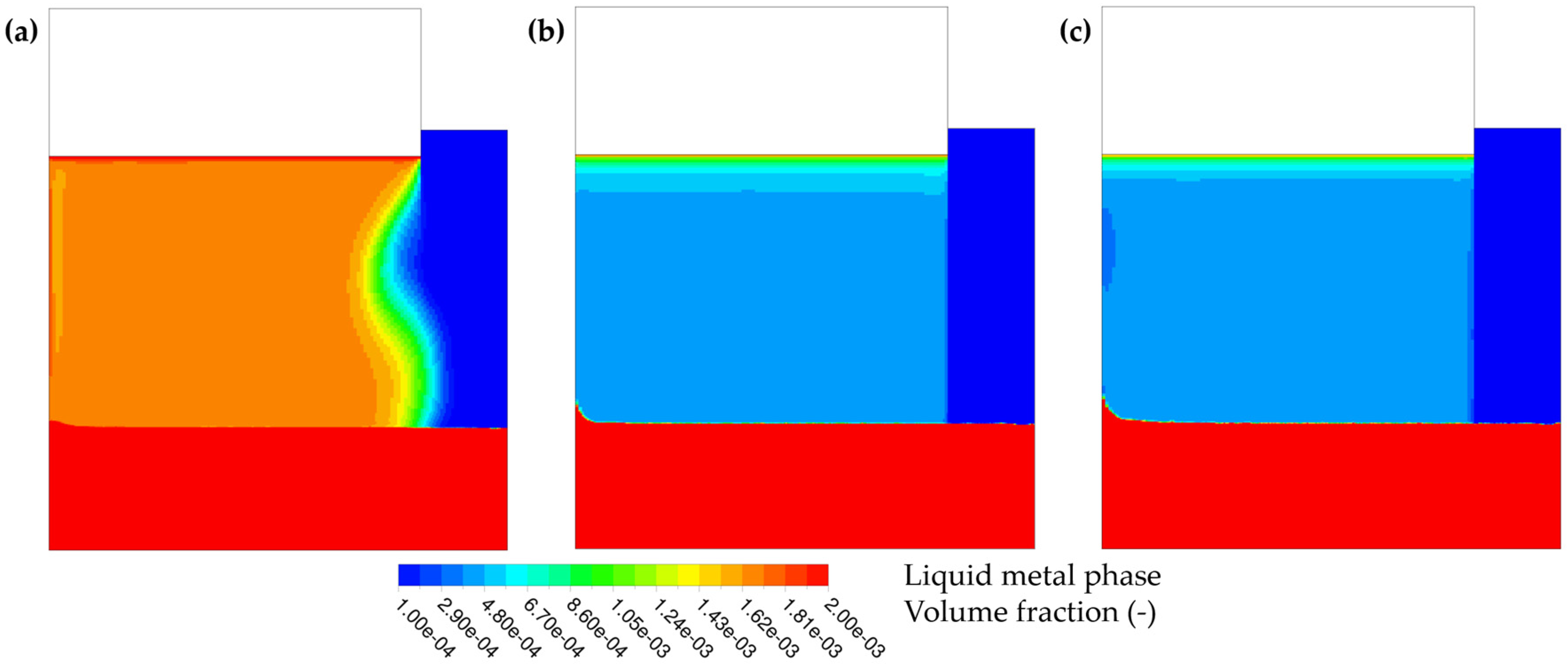
3D simulations highlighted than liquid metal droplets exhibit a wide size range [15,28]. During an ESR operation, some slag were taken from the region between the slag and ingot and a 7 mm metal drop has been found [28], supporting the hypothesis that drop diameter may lie between 1 and 10 mm. As one unique diameter is set in the model, several simulations have been performed to investigate separately the influence of each drop size on the hydrodynamics and heat transfer.
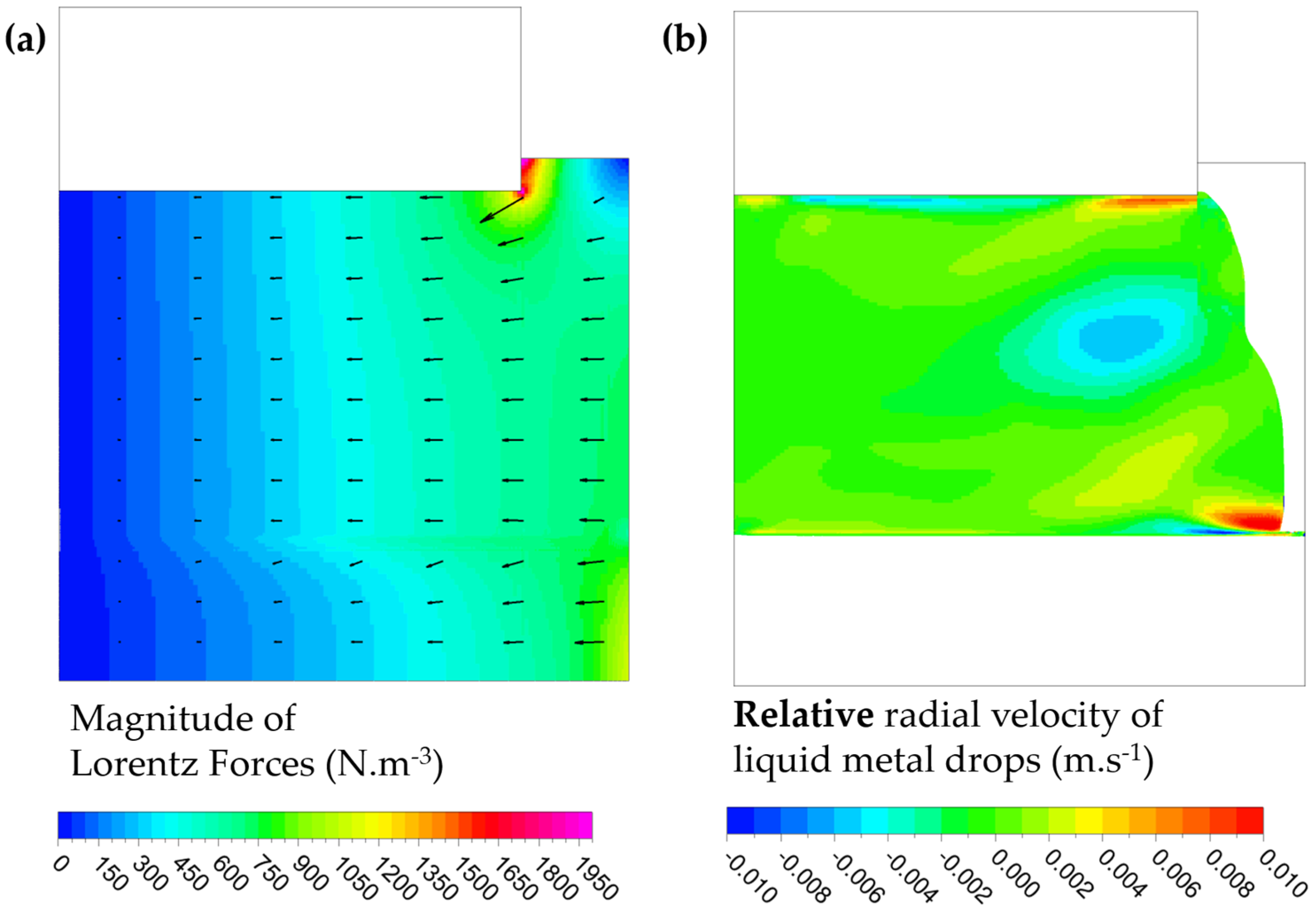
A change in the drop diameter first affects the drop terminal velocity. For instance, reducing the diameter from 10 to 5 mm, then to 1 mm, decreases the terminal velocity from 0.41 to 0.38 m·s−1, then to 0.10 m·s−1. Hence, the residence time increases to nearly 2 s for the smallest drops. This explains the higher volume fraction calculated in the latter case, as presented in Figure 9a. This figure also reveals that droplets trajectory is not anymore purely axial, as it is for larger drops. In fact, droplets near the electrode corner are deviated toward the axis by the strong Lorentz forces (see Figure 10a), and this motion is also maintained by the slag flow in this zone. Resulting drop radial velocity is plotted in Figure 10b.
The 5 and 10 mm drops here acquire a quite similar terminal velocity. The drag law used in this model (Equation (11)) reflects the speed reduction due to the drop deformation and its internal circulation. Both phenomena are more significant for the 10 mm drops, thus their terminal velocity remains within the same range as for drops with a diameter 2 times lower (which are 8 times lighter). The volume fraction fields for 5 and 10 mm drops are then similar, except in the zone where acceleration is nonzero.
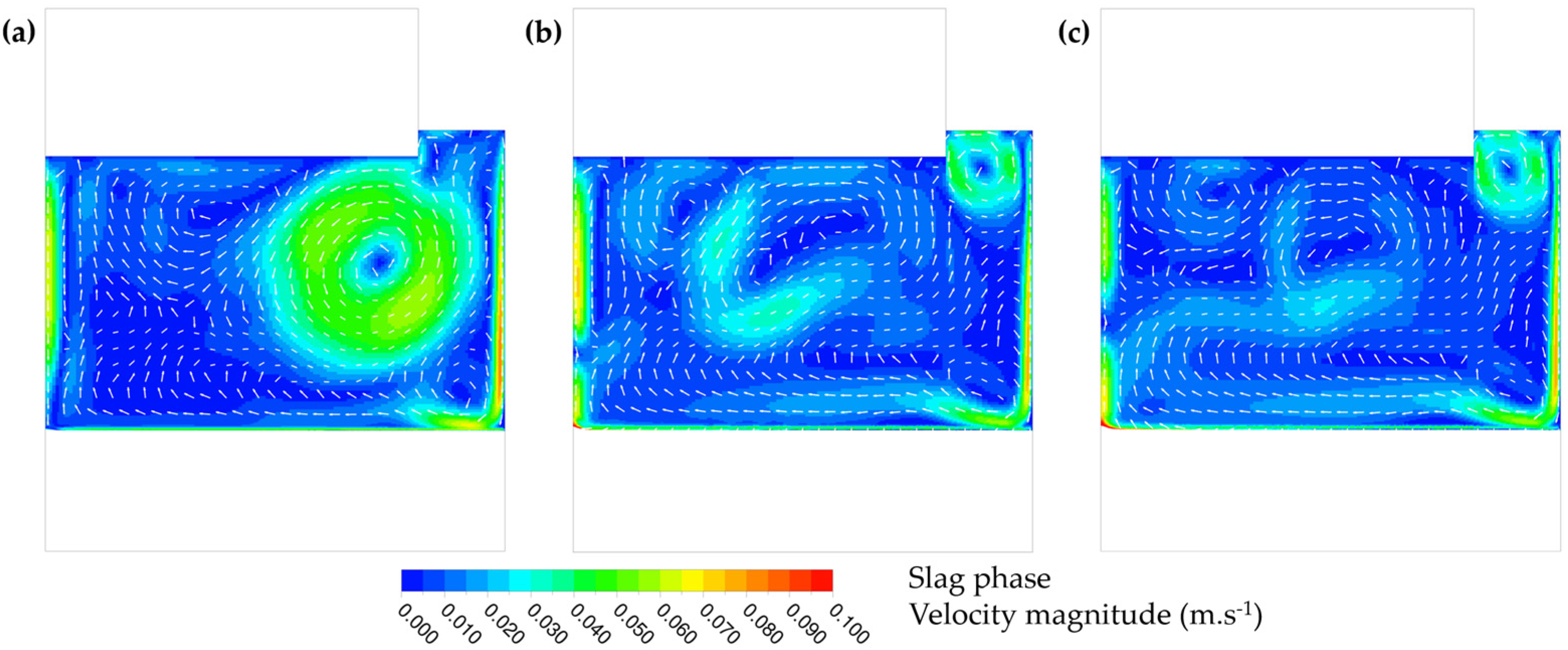
Considering large drops (5 and 10 mm diameter, Figure 11b,c), slag hydrodynamics is quite similar to the case where the drop fall is not considered (Figure 6a). As the metal volume fraction is small and homogeneously distributed, these big drops does not have a strong influence on slag motion.
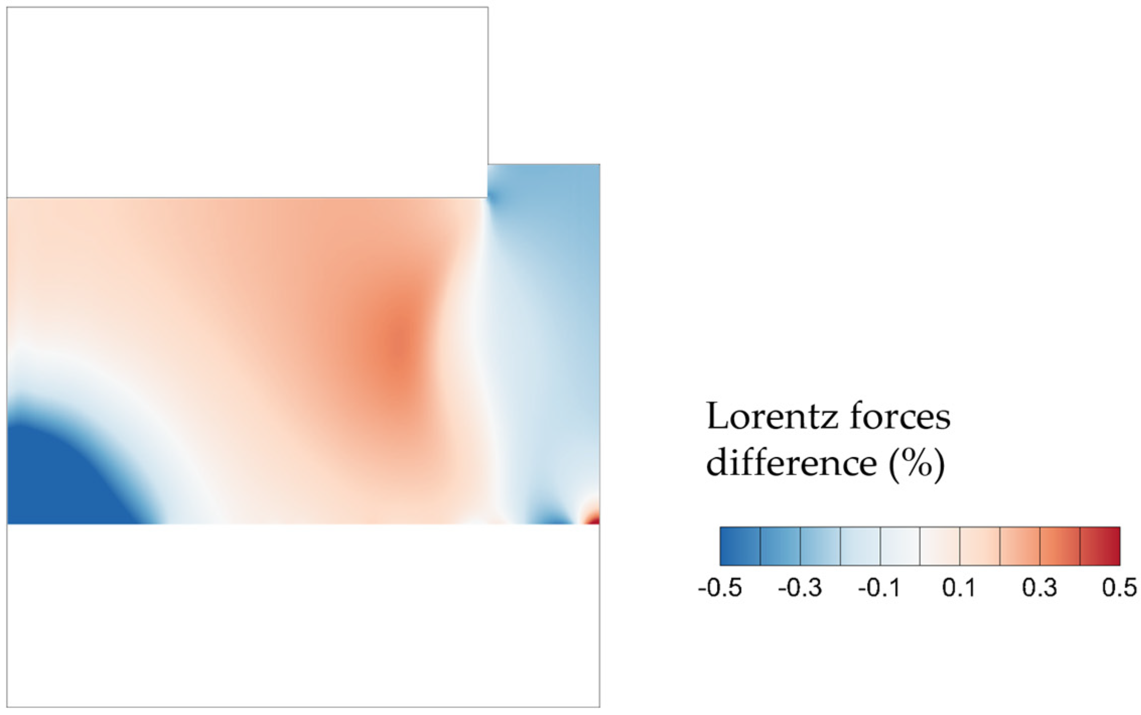
In opposite, in the case of smaller drops—here 1 mm diameter (Figure 11a)—the slag hydrodynamics is greatly modified. The flow loop governed by electromagnetic forces seems to be predominant. The electrical conductivity of the mixture is around 251 Ω−1·m−1, so electromagnetic field is mostly the same as for other cases. As shown by Figure 12, Lorentz forces calculated for the case with 1 mm droplets are sensibly similar than in the single phase case. A small increase around 0.5% is predicted in the region where the electro-vortex intensifies. Nevertheless, as electromagnetokinetic effect is introduced is the model (factor 3/2 on the drop’s Lorentz force), these droplets get higher momentum in the radial direction. This additional momentum is then transferred to the slag by a mechanism of drag interaction. The electro-vortex is then strengthened by the presence of small droplets, not because of a change in the electromagnetic field (almost the same), but only because of hydrodynamic interactions.
These results indicate that in addition to natural buoyancy and Lorentz forces, the momentum interaction with the dispersed droplet phase has to be considered in order to predict accurately slag behavior.
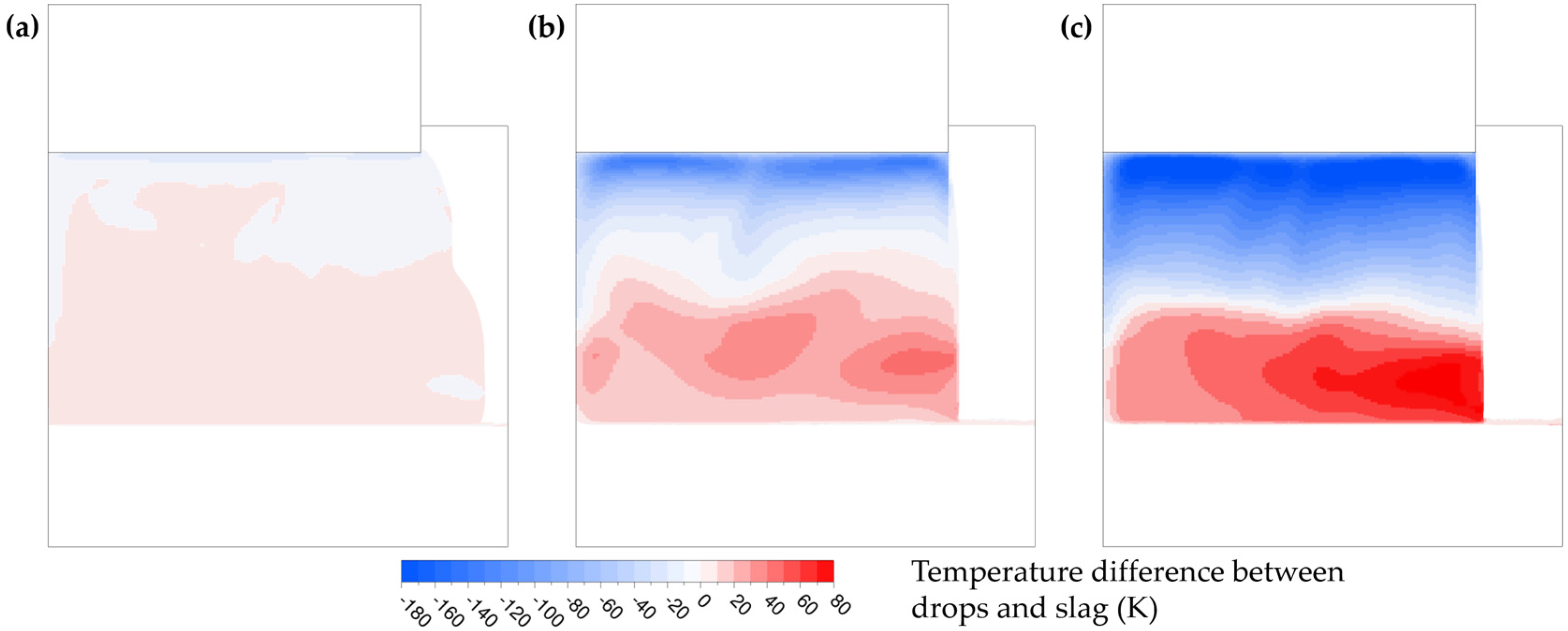
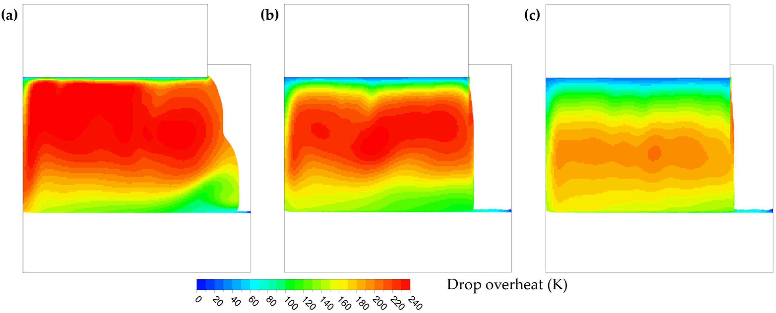
The size of the drops also affects the heat exchange: small droplets are almost in thermal equilibrium with the slag, while larger ones are not, as illustrated in Figure 13. Slag temperature distribution is similar in these three cases, so the maximum overheat is reached for the smallest droplets. However, during their fall in the bottom part of the slag cap—which is cooler—these small droplets also lose more quickly their overheat, while bigger drops remain hotter than the surrounding slag. Hence, 10 mm drops bring more enthalpy to the melt pool than 1 mm drops. Drop overheats are compared in Figure 14.
As already stated, in most engineering models of the ESR process, the enthalpy provided to the liquid pool by the drops is computed considering that they are in thermal equilibrium with the slag right above the interface. The cases presented here point out that this assumption is not verified for large droplets, which remains hotter than the slag above the melt pool.
4. Conclusions
A 2D thermo-magnetohydrodynamic diphasic model based on a Euler–Euler approach has been developed to study the behavior of liquid metal drops falling through the slag bath during electroslag remelting. This method is suitable to simulate full-scale operations, which is not the case for 2D axisymmetric models using the VOF technique.
This study highlights new insights, which are valuable to improve the description of heat and momentum transfer in a comprehensive model of the ESR process:
- Small drops have a strong effect on the flow, not because of a change in electromagnetic field, but due to their great momentum exchange with the slag;
- Large drops have a more important effect on heat transfer, and are found quite far from thermal equilibrium with the slag;
- Small metallic droplets transfer efficiently their momentum to the slag hydrodynamic. In opposite, slag hydrodynamic remains relatively unaffected by the presence of larger droplets, which release their momentum inside the liquid metal pool.
Thermal equilibrium between drops and slag and the fact that hydrodynamics is mainly driven by buoyancy and Lorentz forces are classic assumptions used in engineering models of electroslag remelting. It may be necessary to reassess them for some cases.
Author Contributions
Conceptualization, A.K., M.W., A.L. and A.J.; investigation, J.C.; supervision, A.K., S.C., B.D., S.H. and A.J.; visualization, J.C.; writing—original draft, J.C.; writing—review and editing, A.K., S.C., B.D., S.H. and A.J. All authors have read and agreed to the published version of the manuscript.
Funding
This research was funded by the French National Research and Technology Association, CIFRE funding #2017–1585 (Aubert & Duval Company). This research was also funded by the Austrian Federal Ministry of Economy, Family and Youth and the National Foundation for Research, Technology and Development within the framework of the Christian-Doppler Laboratory for Metallurgical Applications of Magnetohydrodynamics (Abdellah Kharicha).
Acknowledgments
Jérémy Chaulet acknowledges mobility grant from the Erasmus + Agency. Abdellah Kharicha acknowledges financial support from the Austrian Federal Ministry of Economy, Family and Youth and the National Foundation for Research, Technology and Development within the framework of the Christian-Doppler Laboratory for Metallurgical Applications of Magnetohydrodynamics.
Conflicts of Interest
The authors declare no conflict of interest.
References
- Hoyle, G. Electroslag Processes: Principles and Practice; Applied Science Publishers: London, UK, 1983. [Google Scholar]
- Ballantyne, A.S. Heat Flow in Consumable Electrode Remelted Ingots. Ph.D. Thesis, University of British Columbia, Vancouver, BC, Canada, 1978. [Google Scholar]
- Jardy, A.; Ablitzer, D.; Wadier, J.F. Modeling of Movements and Heat Transfer in ESR Slags. In Proceedings of the International Conference on Vacuum Metallurgy, Linz, Austria, 30 September–4 October 1985; Volume 2, pp. 1152–1173. [Google Scholar]
- Dilawari, A.H.; Szekely, J. A mathematical model of slag and metal flow in the ESR Process. Metall. Trans. B 1977, 8, 227–236. [Google Scholar] [CrossRef]
- Choudhary, M.; Szekely, J. The modeling of pool profiles, temperature profiles and velocity fields in ESR systems. Metall. Trans. B 1980, 11, 439–453. [Google Scholar] [CrossRef]
- Ferng, Y.M.; Chieng, C.C.; Pan, C. Numerical Simulations of Electro-Slag Remelting Process. Numer. Heat Transf. Part Appl. 1989, 16, 429–449. [Google Scholar] [CrossRef]
- Jardy, A.; Ablitzer, D.; Wadier, J.F. Magnetohydronamic and thermal behavior of electroslag remelting slags. Metall. Trans. B 1991, 22, 111–120. [Google Scholar] [CrossRef]
- Weber, V.; Jardy, A.; Dussoubs, B.; Ablitzer, D.; Rybéron, S.; Schmitt, V.; Hans, S.; Poisson, H. A Comprehensive Model of the Electroslag Remelting Process: Description and Validation. Metall. Mater. Trans. B 2009, 40, 271–280. [Google Scholar] [CrossRef]
- Hugo, M.; Dussoubs, B.; Jardy, A.; Escaffre, J.; Poisson, H. Influence of the Mold Current on the Electroslag Remelting Process. Metall. Mater. Trans. B 2016, 47, 2607–2622. [Google Scholar] [CrossRef]
- Yanke, J.; Fezi, K.; Fahrmann, M.; Krane, M.J.M. Predicting Melting Behavior of an Industrial Electroslag Remelting Ingot. In Proceedings of the 2013 International Symposium on Liquid Metal Processing & Casting, Austin, TX, USA, 22–25 September 2013; pp. 47–55. [Google Scholar]
- Karimi-Sibaki, E.; Kharicha, A.; Wu, M.; Ludwig, A.; Holzgruber, H.; Ofner, B.; Ramprecht, M. A Numerical Study on the Influence of the Frequency of the Applied AC Current on the Electroslag Remelting Process. In Proceedings of the 2013 International Symposium on Liquid Metal Processing & Casting, Austin, TX, USA, 22–25 September 2013; pp. 13–19. [Google Scholar]
- Kharicha, A.; Ludwig, A.; Wu, M. 3D Simulation of the Melting during an industrial scale Electro-slag remelting process. In Proceedings of the International Symposium on Liquid Metal Processing & Casting, Nancy, France, 25–28 September 2011; pp. 41–48. [Google Scholar]
- Giesselmann, N.; Rückert, A.; Eickhoff, M.; Pfeifer, H.; Tewes, J.; Klöwer, J. Coupling of Multiple Numerical Models to Simulate Electroslag Remelting Process for Alloy 718. ISIJ Int. 2015, 55, 1408–1415. [Google Scholar] [CrossRef] [Green Version]
- Liu, S.; He, Z.; Hui, C.; Wang, Q.; Li, B. Numerical simulation of the formation and the dripping of droplet in the Electroslag Remelting process. Therm. Sci. 2017, 21, 1241–1250. [Google Scholar] [CrossRef]
- Li, B.; Li, R.; Wang, B. Formation and Drop of Metal Droplets in Slag Bath of Electroslag Remelting Processes. In Materials Processing Fundamentals; Springer: Cham, Switzerland, 2013; pp. 39–44. ISBN 978-3-319-48584-3. [Google Scholar]
- Wang, Q.; Zhao, R.; Fafard, M.; Li, B. Three-dimensional magnetohydrodynamic two-phase flow and heat transfer analysis in electroslag remelting process. Appl. Therm. Eng. 2015, 80, 178–186. [Google Scholar] [CrossRef]
- Wang, Q.; Li, B. Numerical investigation on the effect of fill ratio on macrosegregation in electroslag remelting ingot. Appl. Therm. Eng. 2015, 91, 116–125. [Google Scholar] [CrossRef]
- Yu, J.; Jiang, Z.; Liu, F.; Chen, K.; Li, H.; Geng, X. Effects of Metal Droplets on Electromagnetic Field, Fluid Flow and Temperature Field in Electroslag Remelting Process. ISIJ Int. 2017, 57, 1205–1212. [Google Scholar] [CrossRef] [Green Version]
- Giesselmann, N. Numerische Untersuchungen des Elektroschlacke-Umschmelzprozesses für Alloy 718. Ph.D. Thesis, RWTH Aachen University, Aachen, Germany, 2014. [Google Scholar]
- Kharicha, A.; Ludwig, A.; Wu, M. Shape and stability of the slag/melt interface in a small dc ESR process. Mater. Sci. Eng. A 2005, 413, 129–134. [Google Scholar] [CrossRef]
- Dong, Y.-W.; Jiang, Z.-H.; Fan, J.-X.; Cao, Y.-L.; Hou, D.; Cao, H.-B. Comprehensive Mathematical Model for Simulating Electroslag Remelting. Metall. Mater. Trans. B 2016, 47, 1475–1488. [Google Scholar] [CrossRef]
- Huang, X.; Li, B.; Liu, Z.; Yang, X.; Tsukihashi, F. Numerical study on the removal and distribution of non-metallic inclusions in electroslag remelting process. Int. J. Heat Mass Transf. 2019, 135, 1300–1311. [Google Scholar] [CrossRef]
- Weber, V. Simulation Numérique du Procédé de Refusion Sous Laitier Electroconducteur. Ph.D. Thesis, Institut National Polytechnique de Lorraine, Nancy, France, 2008. [Google Scholar]
- Karimi-Sibaki, E.; Kharicha, A.; Bohacek, J.; Wu, M.; Ludwig, A. On Validity of Axisymmetric Assumption for Modeling an Industrial Scale Electroslag Remelting Process. Adv. Eng. Mater. 2016, 18, 224–230. [Google Scholar] [CrossRef]
- Kharicha, A.; Schützenhöfer, W.; Ludwig, A.; Tanzer, R. Multiphase Modelling of the Slag Region in ESR process. In Proceedings of the 2007 International Symposium on Liquid Metal Processing and Casting, Nancy, France, 2–5 September 2007; pp. 107–111. [Google Scholar]
- Maxwell, J.C. A Treatise on Electricity and Magnetism; Clarendon Press: Oxford, UK, 1873; Volume 1. [Google Scholar]
- Leenov, D.; Kolin, A. Theory of Electromagnetophoresis. I. Magnetohydrodynamic Forces Experienced by Spherical and Symmetrically Oriented Cylindrical Particles. J. Chem. Phys. 1954, 22, 683–688. [Google Scholar] [CrossRef]
- Kharicha, A.; Schützenhöfer, W.; Ludwig, A.; Tanzer, R. Numerical and Experimental Investigations on the ESR Process of the Hot Work Tool Steel H11. In Proceedings of the 2009 International Symposium on Liquid Metal Processing and Casting, Santa Fe, NM, USA, 20–23 September 2009; pp. 235–242. [Google Scholar]
- Hu, S.; Kintner, R.C. The fall of single liquid drops through water. AIChE J. 1955, 1, 42–48. [Google Scholar] [CrossRef]
- Loth, E. Quasi-steady shape and drag of deformable bubbles and drops. Int. J. Multiph. Flow 2008, 34, 523–546. [Google Scholar] [CrossRef]
- Clift, R.; Grace, J.R.; Weber, M.E. Bubbles, Drops, and Particles; Academic Press: New York, NY, USA, 1978. [Google Scholar]
- Davies, M.W.; Wright, F.A. The viscosities of calcium fluoride based-slags. Chem. Ind. 1970, 11, 359–363. [Google Scholar]
- Ogino, K.; Hara, S. Density, Surface Tension and Electrical Conductivity of Calcium Fluoride Based Fluxes for Electroslag Remelting. Tetsu-to-Hagane 1977, 63, 2141–2151. [Google Scholar] [CrossRef] [Green Version]
Figure 1.
Schematic representation of the electroslag remelting process.

Figure 2.
Experimental (black) and simulated pool profiles (red), reproduced from reference [23].
Figure 2.
Experimental (black) and simulated pool profiles (red), reproduced from reference [23].

Figure 3.
Comparison of the proposed drag curve (a) and the experimental data of Hu and Kintner (b), reproduced from reference [29] with permission.
Figure 3.
Comparison of the proposed drag curve (a) and the experimental data of Hu and Kintner (b), reproduced from reference [29] with permission.

Figure 4.
Schematic representation of the computational domain.

Figure 5.
Liquid metal volume fraction fields (time-averaged) without drops (a) and considering the drops falling through the slag (b). Normalized velocity vectors of the liquid metal drops are plotted in black on (b).
Figure 5.
Liquid metal volume fraction fields (time-averaged) without drops (a) and considering the drops falling through the slag (b). Normalized velocity vectors of the liquid metal drops are plotted in black on (b).

Figure 6.
Slag phase velocity magnitude and normalized slag velocity vectors (time-averaged) for the case without drops (a) and considering the drops fall (b).
Figure 6.
Slag phase velocity magnitude and normalized slag velocity vectors (time-averaged) for the case without drops (a) and considering the drops fall (b).

Figure 7.
Temperature distribution of the slag phase (time-averaged) for the case without drops (a) and considering the drops fall (b).
Figure 7.
Temperature distribution of the slag phase (time-averaged) for the case without drops (a) and considering the drops fall (b).

Figure 8.
Drop overheat (a) and temperature difference between the drops and the slag (b) (time-averaged) for the 5 mm falling drops.
Figure 8.
Drop overheat (a) and temperature difference between the drops and the slag (b) (time-averaged) for the 5 mm falling drops.

Figure 9.
Liquid metal volume fraction (time-averaged) considering the fall of 1 mm (a), 5 mm (b) and 10 mm (c) liquid metal drops.
Figure 9.
Liquid metal volume fraction (time-averaged) considering the fall of 1 mm (a), 5 mm (b) and 10 mm (c) liquid metal drops.

Figure 10.
Magnitude of Lorentz forces and vectors (a) and radial velocity of 1 mm diameter liquid metal drops (b) (time-averaged).
Figure 10.
Magnitude of Lorentz forces and vectors (a) and radial velocity of 1 mm diameter liquid metal drops (b) (time-averaged).

Figure 11.
Slag phase velocity magnitude and normalized slag velocity vectors (time-averaged) considering the fall of 1 mm (a), 5 mm (b) and 10 mm (c) drops.
Figure 11.
Slag phase velocity magnitude and normalized slag velocity vectors (time-averaged) considering the fall of 1 mm (a), 5 mm (b) and 10 mm (c) drops.

Figure 12.
Difference of Lorentz forces (in %) between the case with 1 mm droplets and without droplets.
Figure 12.
Difference of Lorentz forces (in %) between the case with 1 mm droplets and without droplets.

Figure 13.
Temperature difference between drops and slag (time-averaged) considering the fall of 1 mm (a), 5 mm (b) and 10 mm (c) drops.
Figure 13.
Temperature difference between drops and slag (time-averaged) considering the fall of 1 mm (a), 5 mm (b) and 10 mm (c) drops.

Figure 14.
Drop overheat (time-averaged) considering the fall of 1 (a), 5 (b) and 10 mm (c) drops.


Table 1.
Geometry and operating conditions of the reference case.
| Electrode Radius (m) | 0.215 |
| Inner mold radius (m) | 0.265 |
| Electrode immersion depth (m) | 0.015 |
| Electrode–ingot distance (m) | 0.157 |
| Droplet diameter (mm) | 1; 5; 10 |
| Electrode melt rate (kg.min−1) | 10 |
| Electric current intensity (kA) | 15 |
Table 2.
Summary of the boundary conditions.
| Boundary 1 | Description | Electromagnetic | Hydrodynamic | Thermal |
|---|---|---|---|---|
| a. | symmetry axis | Bθ = 0 | free slip | no flux |
| b. | top of the calculation domain | no flux | - | no flux |
| c. | vertical electrode wall | Ampère’s circuital law (18) | - | - |
| d. | slag surface | Ampère’s circuital law (18) | free slip | radiative heat transfer |
| e. | slag-mold and mold-ingot interface | Ampère’s circuital law (18) | no slip | slag liquidus temperature |
| f. | bottom of the domain | no flux | no slip | metal liquidus temperature |
| g. | vertical immersed electrode wall | coupled | no slip | metal liquidus temperature |
| h. | horizontal immersed electrode wall | coupled | no slip | metal liquidus temperature |
1 Boundary nomenclature refers to Figure 4.
Table 3.
Physical properties of the liquid metal and slag needed by the model, obtained from references [25,32,33] and CALPHAD computation (Thermo-Calc, TCFE9).
| Physical Property | Liquid Metal (Low-Alloyed Steel) | Liquid Slag (70/15/15 Type) |
|---|---|---|
| Dynamic viscosity η (kg·m−1·s−1) | 0.006 | 0.008 |
| Density ρ (kg·m−3) | 6940 | 2765 |
| Liquidus temperature (K) | 1763 | 1733 |
| Thermal expansion coefficient β (K−1) | 1.1 × 10⁻⁴ | 7.5 × 10⁻⁵ |
| Thermal conductivity λ (W·m−1·K−1) | 30 | 35 |
| Specific heat capacity Cp (J·kg−1·K−1) | 690 | 1380 |
| Electrical conductivity σ (Ω−1·m−1) | 106 | 250 |
© 2020 by the authors. Licensee MDPI, Basel, Switzerland. This article is an open access article distributed under the terms and conditions of the Creative Commons Attribution (CC BY) license (http://creativecommons.org/licenses/by/4.0/).
Share and Cite
MDPI and ACS Style
Chaulet, J.; Kharicha, A.; Charmond, S.; Dussoubs, B.; Hans, S.; Wu, M.; Ludwig, A.; Jardy, A. A 2D Multiphase Model of Drop Behavior during Electroslag Remelting. Metals 2020, 10, 490. https://doi.org/10.3390/met10040490
AMA Style
Chaulet J, Kharicha A, Charmond S, Dussoubs B, Hans S, Wu M, Ludwig A, Jardy A. A 2D Multiphase Model of Drop Behavior during Electroslag Remelting. Metals. 2020; 10(4):490. https://doi.org/10.3390/met10040490
Chicago/Turabian StyleChaulet, Jérémy, Abdellah Kharicha, Sylvain Charmond, Bernard Dussoubs, Stéphane Hans, Menghuai Wu, Andreas Ludwig, and Alain Jardy. 2020. "A 2D Multiphase Model of Drop Behavior during Electroslag Remelting" Metals 10, no. 4: 490. https://doi.org/10.3390/met10040490
Note that from the first issue of 2016, this journal uses article numbers instead of page numbers. See further details here.