Article

Ionic Transport Properties of Cation-Exchange Membranes Prepared from Poly(vinyl alcohol-b-sodium Styrene Sulfonate)

1
Graduate School of Sciences and Technology for Innovation, Yamaguchi University, 2-16-1 Tokiwadai, Ube Yamaguchi 755-8611, Japan
2
Blue Energy Center for SGE Technology (BEST), 2-16-1 Tokiwadai, Ube City, Yamaguchi 755-8611, Japan
3
Department of Chemical Engineering, Faculty of Engineering, Universiti Malaya, Kuala Lumpur 50603, Malaysia
*
Author to whom correspondence should be addressed.
Membranes 2021, 11(6), 452; https://doi.org/10.3390/membranes11060452
Submission received: 14 May 2021 / Revised: 14 June 2021 / Accepted: 16 June 2021 / Published: 19 June 2021
(This article belongs to the Special Issue Novel Ion-Exchange Membranes)

Abstract

:
Membrane resistance and permselectivity for counter-ions have important roles in determining the performance of cation-exchange membranes (CEMs). In this study, PVA-based polyanions—poly(vinyl alcohol-b-sodium styrene sulfonate)—were synthesized, changing the molar percentages CCEG of the cation-exchange groups with respect to the vinyl alcohol groups. From the block copolymer, poly(vinyl alcohol) (PVA)-based CEMs, hereafter called “B-CEMs”, were prepared by crosslinking the PVA chains with glutaraldehyde (GA) solution at various GA concentrations CGA. The ionic transport properties of the B-CEMs were compared with those previously reported for the CEMs prepared using a random copolymer—poly(vinyl alcohol-co-2-acrylamido-2-methylpropane sulfonic acid)—hereafter called ”R-CEMs”. The B-CEMs had lower water content than the R-CEMs at equal molar percentages of the cation-exchange groups. The charge density of the B-CEMs increased as CCEG increased, and reached a maximum value, which increased with increasing CGA. A maximum charge density of 1.47 mol/dm3 was obtained for a B-CEM with CCEG = 2.9 mol% and CGA = 0.10 vol.%, indicating that the B-CEM had almost two-thirds of the permselectivity of a commercial CEM (CMX: ASTOM Corp. Japan). The dynamic transport number and membrane resistance of a B-CEM with CCEG = 8.3 mol% and CGA = 0.10 vol.% were 0.99 and 1.6 Ωcm2, respectively. The B-CEM showed higher dynamic transport numbers than those of the R-CEMs with similar membrane resistances.

1. Introduction

In recent years, cation-exchange membranes (CEMs) have received considerable attention from researchers and manufacturers, and have been widely used for various industrial purposes [1], such as the separation of metal ion pollutants from hard water [2], chlor-alkali electrolysis [3], fuel cells [4,5,6,7,8,9], electrodialytic concentration or desalination of electrolyte solutions [1,3,10], redox flow batteries [11,12,13], reverse electrodialysis [14,15,16], and hydrogen production [17,18,19]. CEMs contain fixed, negatively charged groups that allow cations to pass through the membranes while concurrently rejecting anions. Most commercially available CEMs for electrodialysis are made of styrene-co-divinylbenzene matrices or other conjugated polymers. However, the use of this type of membrane is limited by difficulties in controlling the membrane structure due to simultaneous copolymerization and crosslinking. Furthermore, the cost of manufacturing CEMs is relatively high. Therefore, many novel CEMs have been developed recently to overcome these problems [20,21,22]. These CEMs offer better control over the distribution of the fixed charges, and exhibit similar performance to conventional cation-exchange membranes. Some ion-exchange membranes (IEMs) are prepared via the combination of water-soluble base polymers and polyelectrolytes, followed by crosslinking of the base polymers. The obtained IEM has a semi-interpenetrating network (semi-IPN) structure, meaning that the polyelectrolyte chains are fixed in a crosslinked polymer matrix. The ion-exchange capacity of IEMs thus obtained can be easily controlled via changes to the mixture ratio of the base polymer to the polyelectrolyte. One widely used water-soluble base polymer—poly(vinyl alcohol) (PVA)—is a polyhydroxy polymer that has favorable physicochemical properties [23,24,25,26] for use as a base polymer in IEMs. PVA has a low methanol permeability; hence, there have been many reports of PVA-based CEMs for direct methanol fuel cell applications [27,28,29,30,31,32,33]. Various types of PVA-based CEMs with semi-IPN structures have been prepared; however, the stability of such CEMs in aqueous solutions is a potential disadvantage. To overcome this disadvantage, CEMs with IPN structures have been prepared from a mixture of PVA and PVA-based polyanions [34,35,36,37]. CEMs with IPN structures consist of crosslinked polymers in which negatively charged groups are fixed covalently; hence, they show higher long-term aqueous stability than CEMs with semi-IPN structures. However, CEMs with IPN structures prepared from a random copolymer—poly(vinyl alcohol-co-2-acrylamido-2-methylpropane sulfonic acid [37]—hereafter called “R-CEMs”, showed much lower transport properties than commercially available CEMs.
The aim of this study was to prepare a PVA-based CEM with superior higher counter-ion transport properties to R-CEMs. To this end, samples of a block copolymer of vinyl alcohol and sodium p-styrenesulfonate groups (hereafter referred to as PVA-b-PSSS) with various ratios of cation-exchange groups were polymerized. CEMs with IPN structures were prepared from the block copolymer, hereafter called “B-CEMs”. Figure 1 shows the chemical structure of the PVA-b-PSSS. The crystalline region of the semicrystalline PVA acts as a physical crosslink point. In a film-forming process involving the PVA-based block copolymer, microphase separation of the PVA phase and the charged phase occurs, while heat treatment increases the crystallinity of the PVA region. During this process, the charged groups are concentrated into amorphous regions, resulting in the formation of ionic paths with high charge densities in the cation-exchange groups [33,38]. Therefore, the B-CEMs have a higher cation selectivity and lower membrane resistance than those of CEMs with low charge densities. The crystallinity of the PVA region within a B-CEM is higher than that of an R-CEM, because the cation-exchange groups in the random copolymer chains inhibit the formation of crystals. Thus, the B-CEMs have a higher counter-ion permselectivity than the R-CEMs.
In this study, we investigated the differences in the ionic transport properties—i.e., charge density, membrane resistance, and transport number—of PVA-based CEMs prepared from two different copolymers.

2. Experimental Methods

2.1. Materials

SH end group PVA (PVA-SH: 100% hydrolyzed, average Mw = 198,000) was obtained from Kuraray Co., Ltd., Tokyo, Japan. Sodium p-styrenesulfonate (SSS) was purchased from Tosoh Co., Tokyo, Japan. 2,2′-Azobis(2-methylpropionamidine) dihydrochloride (V-50) and analytical grade glutaraldehyde (GA) (25 wt.% solution in water) were purchased from Wako Pure Chemical Industries, Osaka, Japan. Sodium chloride, hydrochloric acid, and potassium chloride (all analytical grade) were purchased from Nacalai Tesque, Kyoto, Japan.

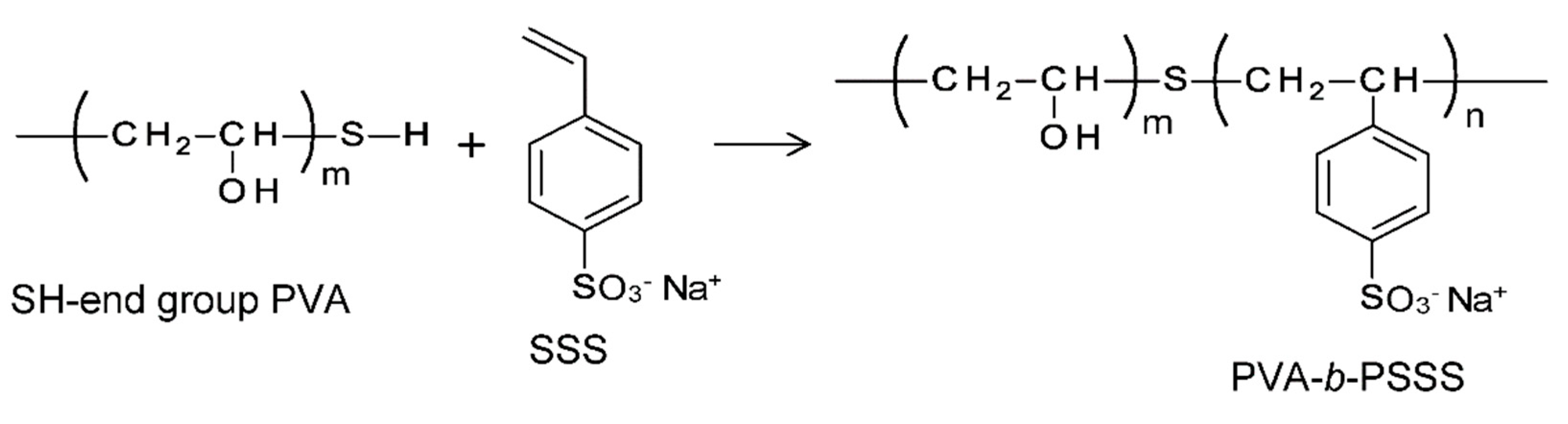
2.2. Synthesis of Block Copolymers

PVA-SH was dissolved in deionized water at 90 °C. Various amounts of SSS were then added to different batches of the solution in order to change the SSS content of the polymer. The mixed aqueous solutions of PVA-SH and SSS were purged with nitrogen gas and stirred for 30 min before the initiator (V-50) was gradually added over 2 h, after which the reaction was allowed to proceed for 1.5 h at 90 °C [39]. After polymerization, the unreacted monomer and homopolymer (polySSS) were removed by precipitation in acetone. The block copolymers were then dried under vacuum at 50 °C to a constant weight. The reaction conditions for the block copolymers are listed in Table 1.

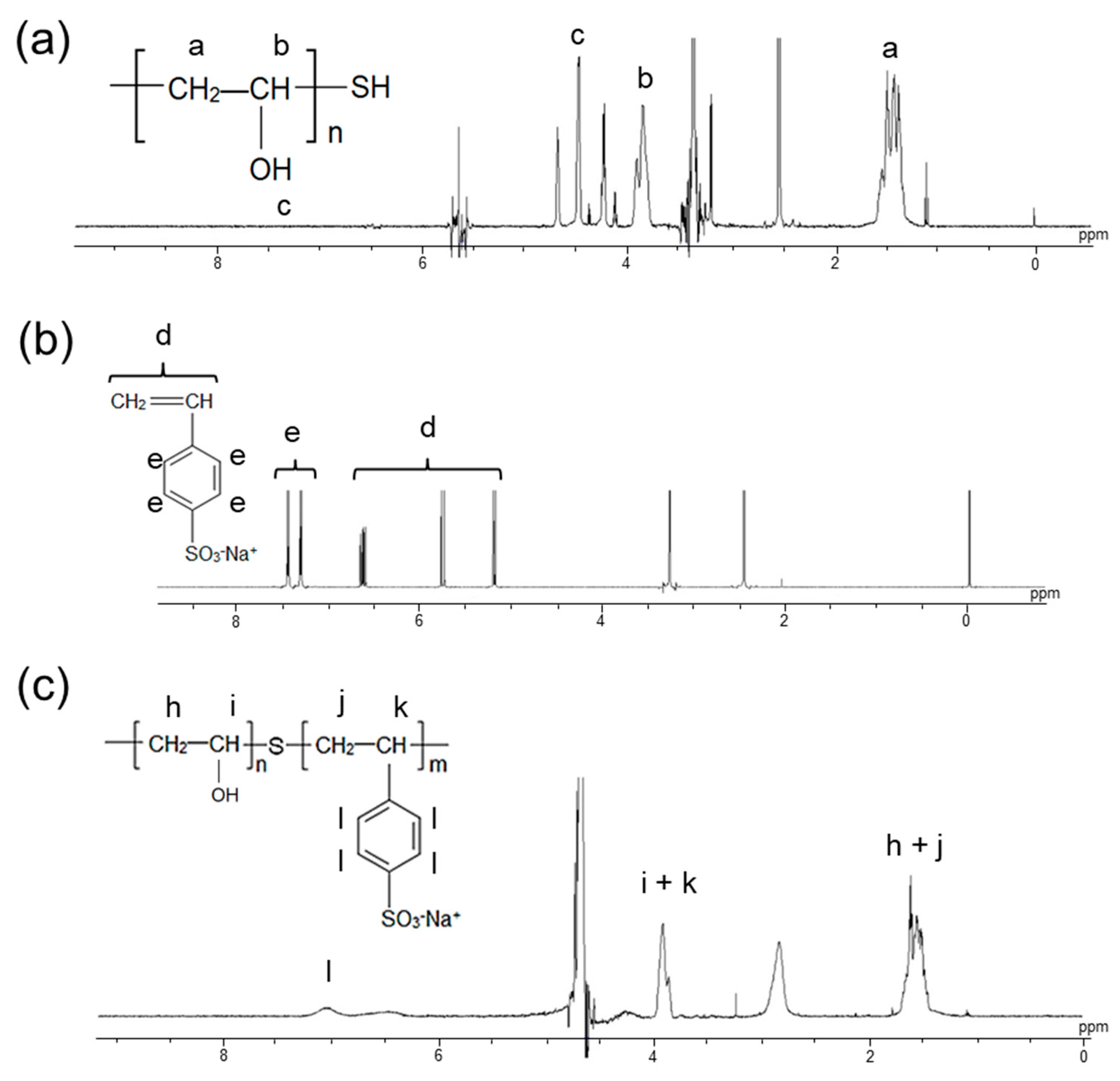
2.3. Analysis of Chemical Structure of Block Copolymers

1H nuclear magnetic resonance (NMR) spectra of the PVA-SH, SSS monomer, and block copolymers were obtained using an NMR spectrometer (JEOL JNM-EX270FT NMR system). Dimethyl sulfoxide (DMSO)-d6 and D2O were used as the solvents, and tetramethylsilane was used as the internal standard. The data were analyzed using commercially available software (JEOL DATYM LTD. ALICE2) to estimate the SSS content of the block copolymers.

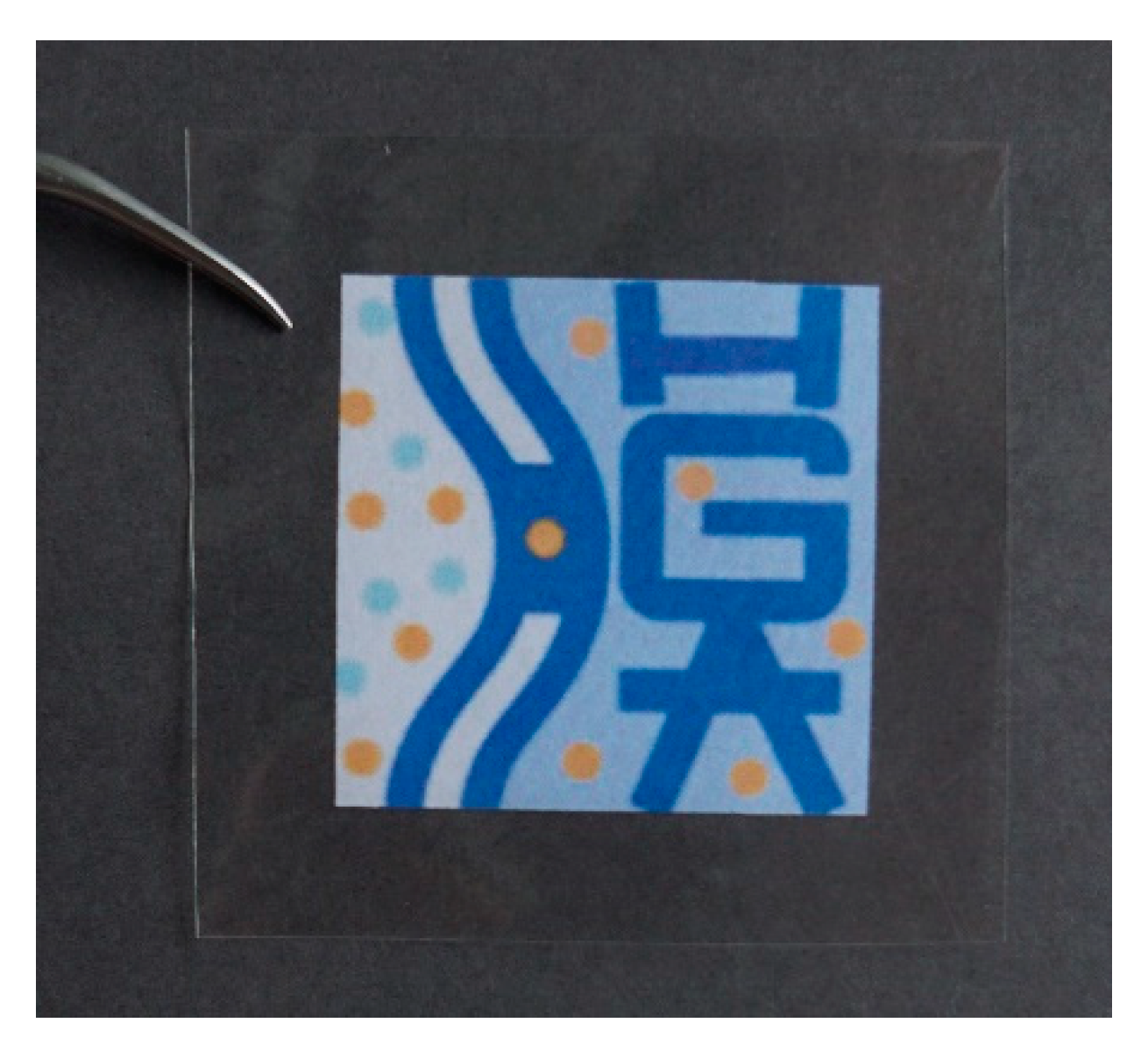
2.4. Preparation of B-CEMs

Aqueous solutions of PVA-b-PSSS with various SSS contents were cast on an acrylic plate and dried over a hot stage (NISSIN, NH-45N) for 24 h overnight at 50 °C. Self-standing base films of the B-CEMs were obtained and annealed under vacuum at 160 °C for 30 min to induce physical crosslinking between the PVA chains. The annealed films were immersed in aqueous solutions containing GA, whose concentrations are shown in Table 2, along with 0.05 mol/dm3 of HCl and 3.0 mol/dm3 NaCl, at 25 °C for 24 h, to facilitate chemical crosslinking. The resulting B-CEMs were kept in 0.1 mol/dm3 NaCl solution in order to maintain an equilibrium swelling state.

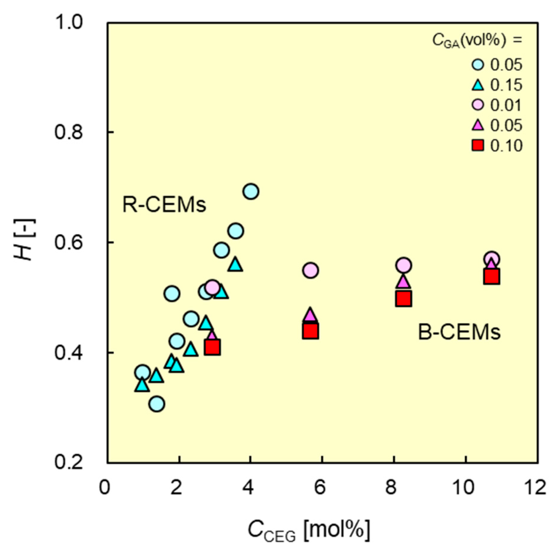
2.5. Measurement of Membrane Water Content

To measure the membrane water content H, the membrane was removed from the 0.1 mol/dm3 NaCl solution, dabbed with filter paper to remove excess water on the membrane surfaces, and the weight of the wet sample membrane immersed in NaCl solution (the counter-ion of the membrane was Na+) Ww was measured. The value of the weight in a dry state Wd measured at the ion-exchange capacity (IEC) was used. The volumetric water content was calculated from Ww and Wd as follows:
Δ H ( W w W d ) / 1.0 ( W w W d ) / 1.0 + W d 1.3
where 1.0 and 1.3 are the densities of water and PVA [40], respectively.

2.6. Measurement of Ion-Exchange Capacity (IEC)

IEC is defined as the milliequivalent of cation-exchange groups per 1 g of dry membrane whose counter-ions are Na+ ions (meq/g-dry-Na form). To measure the IEC of a sample membrane, the membrane of 5 cm × 5 cm was immersed in 0.5 mol/dm3 KCl solution for 6 h to change the counter-ions with K+ ions. The membrane was then immersed in 50 cm3 of 0.3 mol/dm3 of NaNO3 and stirred for 24 h to ensure that all of the K+ counter-ions were exchanged with the Na+ ions in the solution. The concentration of K+ ions CK+ in the solution was measured using an ion chromatograph (Dionex ICS-1500). The membrane was dried under vacuum for 24 h, and its dry weight Wd was measured. The IEC of the membrane was obtained using the following equation:
I E C = C K + W d × 100 1000

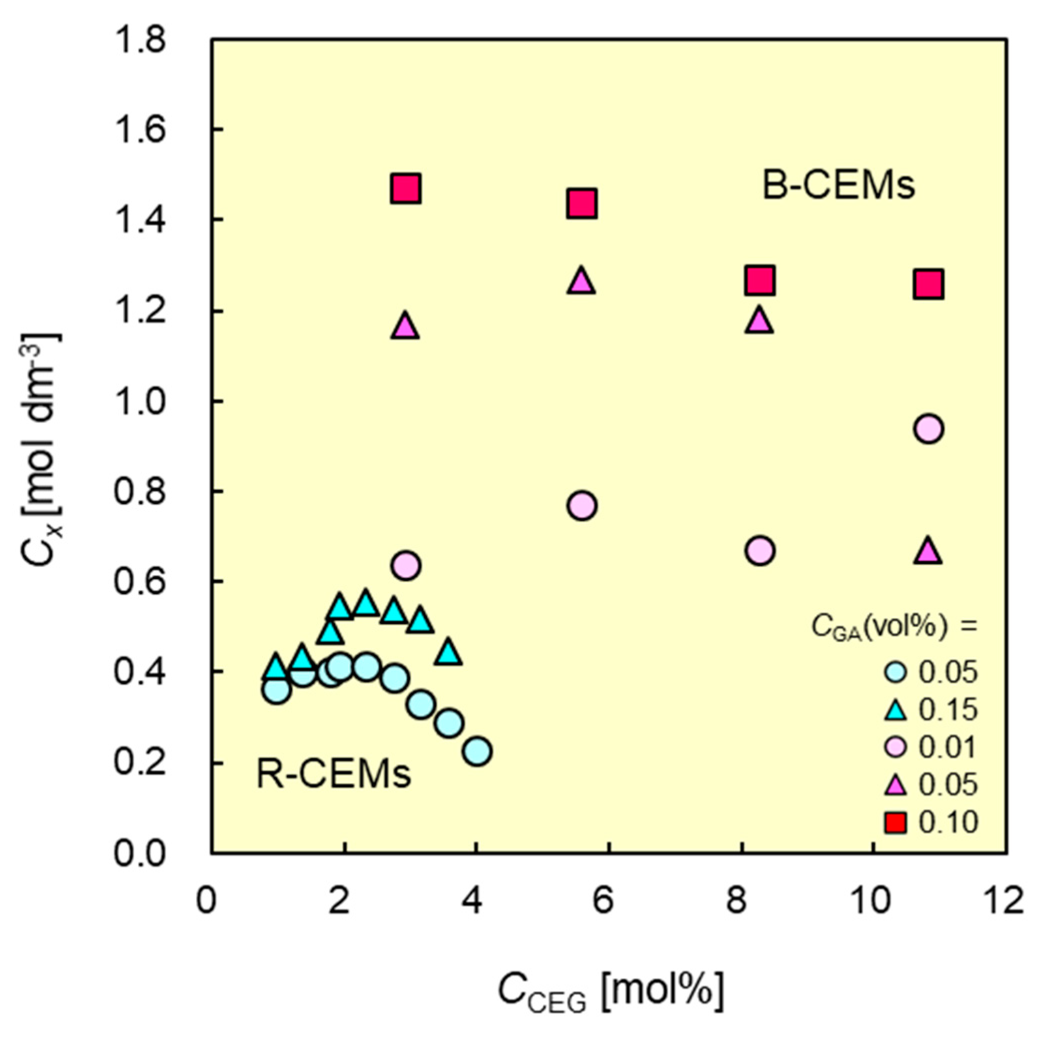
2.7. Determination of Membrane Charge Density

To estimate the charge density of the membrane, the membrane potential Δ φ was measured at 25.0 °C ± 0.5 °C in a diffusion dialysis system with two KCl solutions at different concentrations Co and Cd (r = Cd/Co = 5). The membrane charge density Cx was calculated from the relationship between Δ φ and Co using the following equation [41]:
Δ = R T F ln ( r · C x 2 + ( 2 C 0 ) 2 C x C x 2 + ( 2 r C 0 ) 2 C x ) R T F W ln ( C x 2 + ( 2 r C 0 ) 2 C x W C x 2 + ( 2 C 0 ) 2 C x W )
where W ( ω K ω Cl ) / ( ω K + ω Cl ) ; ω K   and ω Cl are the mobility of K+ and Cl ions, respectively, in the membrane; and F, R, and T are the Faraday constant, gas constant, and absolute temperature, respectively.

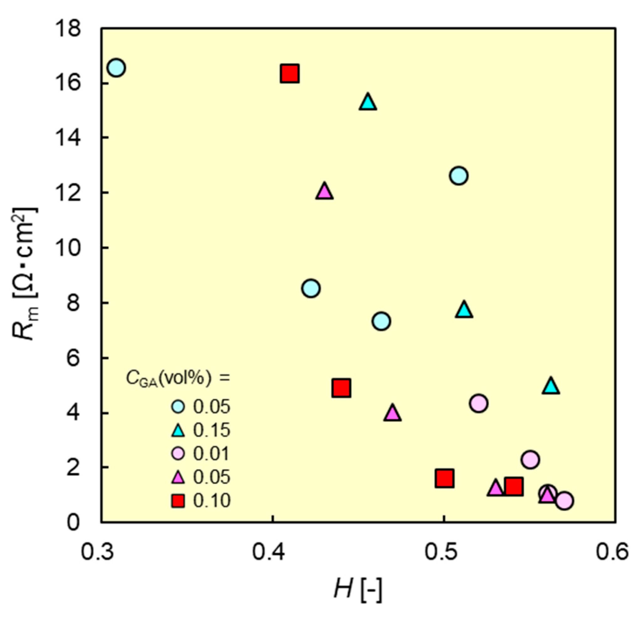
2.8. Measurement of Membrane Resistance

The electrical resistances of the membranes immersed in 0.5 mol/dm3 NaCl were measured using an acrylic plastic cell with an effective measurement area of 1.0 cm2, as described elsewhere [1,41]. During the measurement, 10 kHz AC was applied to Pt electrodes inside the cell. First, the electrical resistance Ro of the 0.5 mol/dm3 NaCl solution was measured at 25.0°C ± 0.5°C. Subsequently, a sample membrane was set in the cell, and the resistance Rs was measured. The membrane resistance Rm was calculated by subtracting Ro from Rs.

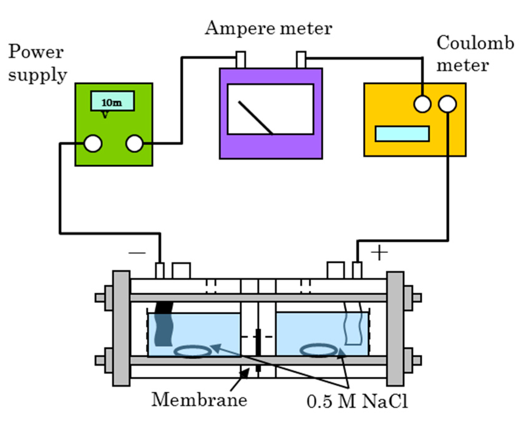
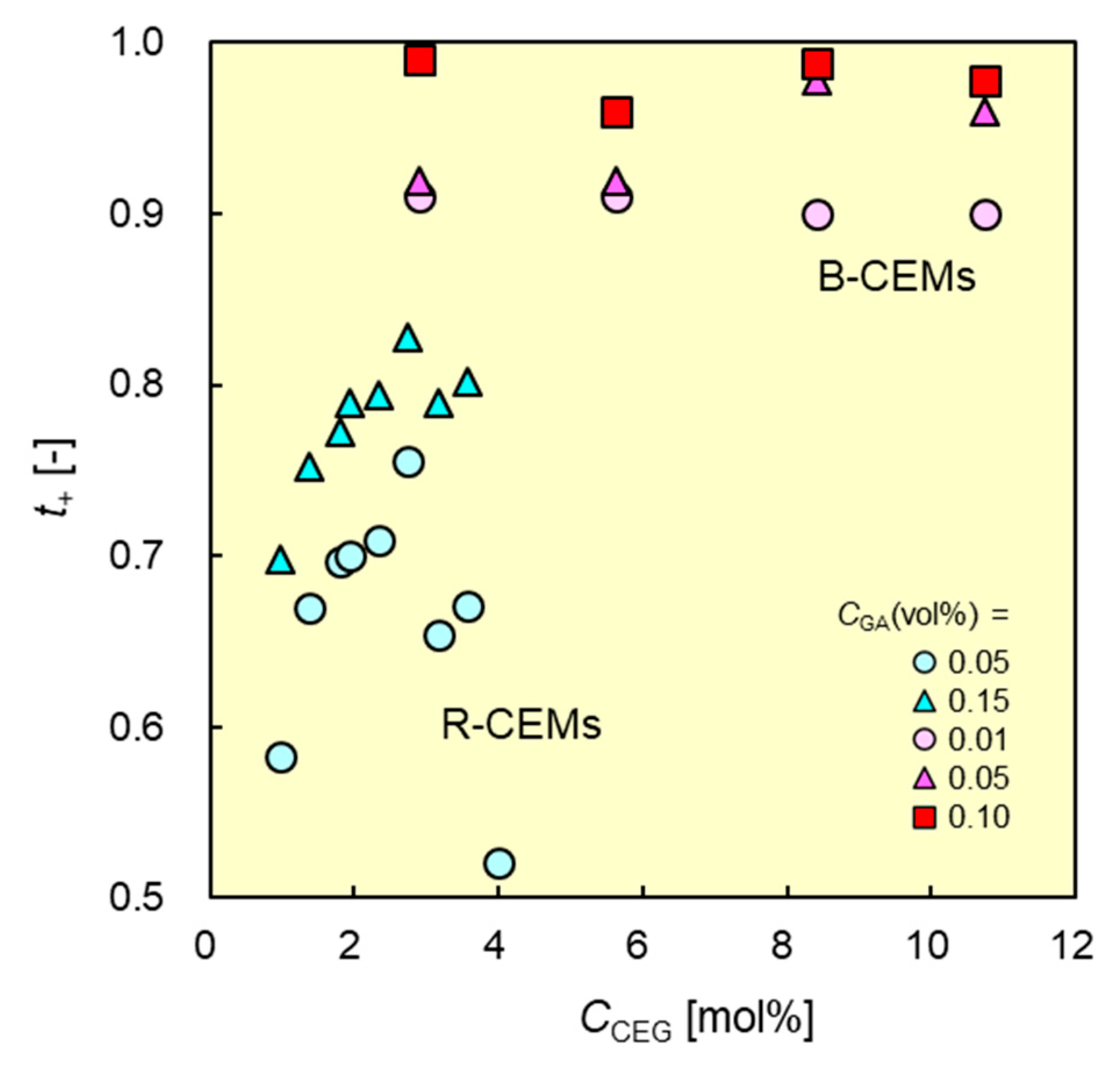
2.9. Measurement of Dynamic State Transport Number

The dynamic state transport number td+ of a sample membrane was determined via electrodialysis (ED) performed using a cell with two chambers separated by a membrane (Figure 2). Direct current was applied between the two electrodes (Ag–AgCl) of the cell containing 0.5 mol/dm3 NaCl in the two chambers at a current density of 10 mA/cm2 at 25 °C [1]. The conductivity change across the two chambers during ED was measured in order to obtain the equivalent change due to ion transport through the membrane. The dynamic state transport number was obtained in terms of the equation:
t d + = Δ m V F Q ,
where Δm, V, and Q are the equivalent change of ions, volume of the solution, and electric charge passing through the membrane during the ED test, respectively.

2.10. Measurement of Mechanical Strength

The mechanical strength, tensile strength, Young’s modulus, and elongation at the breaking point of the wet membranes were measured using a SHIMADZU EZ-Test50N. Specimens with a nominal 20-mm gauge length and 2-mm gauge width were punched out using a dumbbell-type punch. Three specimens were tested at a test speed of 20 mm min−1, and the average values were reported.

3. Results and Discussion

3.1. Characterization of Synthesized Polymer

Figure 3a–c shows the 1H NMR (DMSO-d6) spectra of PVA-SH, SSS monomer, and synthesized block copolymer PVA-b-PSSS, respectively. New peaks corresponding to the aromatic protons of the SSS groups appeared between 7.0 and 8.0 ppm in the spectra of PVA-b-PSSS, indicating that the desired block copolymer was successfully synthesized. The content of SSS groups in the copolymer was defined as the molar ratio of SSS groups to PVA-b-PSSS main chains, which is the same meaning as that of cation-exchange groups in the copolymer CCEG. The value was calculated via the integrals of the aromatic protons of SSS groups at 7.0–8.0 ppm, and those of the methylene groups at 1.2–1.6 ppm. Table 1 shows the reaction conditions, SSS monomer content CmSSS, and CCEG in the graft copolymer calculated from the 1H NMR spectra. CCEG varied from 2.91 to 10.7 mol%, and was essentially proportional to CmSSS. The value of CCEG was approximately 20% lower than that of CmSSS, which may be attributed to incomplete polymerization of the monomer, or to the formation of a homopolymer—poly(SSS)—which was dissolved into acetone during the precipitation process and into the aqueous solution during the crosslinking process.

3.2. Ion-Exchange Capacity and Water Content of B-CEMs as a Function of SSS Content

Figure 4 shows one of the prepared CEMs from PVA-b-PSSS. The CEM was transparent, and had a self-standing membrane even without any supporting material. The preparation conditions, water contents H, and IECs of the B-CEMs are listed in Table 2. CEMs with high IEC values are desirable for the preparation of high-performance IEMs with high permselectivity for cations and low membrane resistance. Conversely, these high IEC values may also result in a degradation of the mechanical properties of the CEMs, because the membrane water content increases with increasing IEC. Therefore, controlling the amount of sulfonate groups in the block copolymers is essential. The IEC values of the B-CEMs were directly proportional to the SSS content of the copolymers, demonstrating that the IEC values can be estimated from the SSS contents of the copolymers. By comparison, the IEC of a commercially available CEM—Neosepta® CMX (ASTOM Corp., Japan)—is 2.0 meq/g-dry. Hence, the IEC of B-CEM-10, B-CEM-11, and B-CEM-12 (10.7 mol% of CCEG) is 70% that of CMX.
Figure 5 shows the water contents of the CEMs as functions of CCEG. To compare the characteristics between B-CEMs and R-CEMs, the data indicated by the blue symbols depict the R-CEMs from a previous study [37]. The water content of both types of IEMs increased with increasing CCEG, owing to the increased the number of charged groups in the CEM, resulting in an increase in the difference between the osmotic pressure inside the membrane and that of the solution in which the membrane was immersed. The CEMs crosslinked with high concentrations of GA had low water contents because the chemical crosslinking with GA increases the number of chemical crosslinking points in the membrane. The B-CEMs had lower water contents than the R-CEMs at the same molar percentage of the cation-exchange groups. For example, the water contents of B-CEM-2 (CCEG = 2.9 mol%; CGA = 0.05 vol.%) and an R-CEM (CCEG = 3.1 mol% and CGA = 0.05 vol.%) were 0.43 and 0.59, respectively; the difference can be attributed to the higher crystallinity of the PVA region in the B-CEM compared to that in the R-CEM. Therefore, it will be difficult to prepare R-CEMs with a CCEG greater than 6 mol% because the CEMs will have water contents greater than 0.8 and, thus, their mechanical strengths will be insufficient to support self-standing membranes.

3.3. Membrane Charge Density as a Function of C C E G

The membrane charge density is defined as the ratio of the molarity of the fixed charged groups to the water volume in the membrane; hence, it is proportional to the ratio of the IEC to the water content of a CEM as:
C x I E C H
The charge density affects the selective cation transport of a CEM. A CEM with high charge density will have a high counter-ion permselectivity. The charge density of both CEMs tends to increase with CCEG, reaching a maximum value (Figure 6). This is because the IEC is directly proportional to the CCEG (Table 2). In addition, H also increased with increasing CCEG (Figure 5). From these points, we can conclude that the charge density initially increased with increasing CCEG because the IEC increased. At high CCEG values, the increase in water content has a greater effect on the charge density than the increase in the IEC. Hence, the charge density decreased after reaching a maximum value. The maximum value of the charge density increased with increasing CGA because H decreased with increasing CGA (Figure 5). B-CEM-3 (CCEG = 2.9 mol%; CGA = 0.10 vol.%) had a maximum value of 1.47 mol/dm3, whereas that of CMX was 1.8 mol/dm3. This indicates that the B-CEM had almost 80% of the charge density of the commercially available CEM. Of all tested CEMs, the B-CEMs exhibited much higher charge densities than the R-CEMs at all tested CGA values. For example, the charge density of B-CEM-2 (CCEG = 2.9 mol%; CGA = 0.05 vol.%) indicated 1.2 mol/dm3, while that of an R-CEM (CCEG = 3.1 mol%; CGA = 0.05 vol.%) was 0.33 mol/dm3. The charge density of the B-CEM was higher than that of the R-CEM, even when the two CEMs had essentially the same CCEG, owing to the lower water content of the former (Figure 5).

3.4. Membrane Resistance as Function of Water Content

Membrane resistance affects the energy efficiency of the electrodialysis process. Figure 7 shows the resistance of PVA-based CEMs as functions of H. The resistance of the fabricated CEMs decreased as CCEG increased, because CEMs with high CCEG had both a high water content and a high IEC. By contrast, the resistance increased with increasing CGA. This result implies that the membrane resistance can be controlled by altering the water content of the CEMs. Of all of the CEMs, B-CEM-10 (CCEG = 10.7 mol%; CGA = 0.01 vol.%) exhibited the lowest membrane resistance of 0.81 Ω cm2.

3.5. Dynamic State Transport Number of CEMs vs. CCEG

The cation permselectivity of a CEM in an ED process can be expressed by dynamic state transport number. An ideal CEM is indicated by a cationic transport number of 1.0, meaning that the CEM allows only the permeation of cations in an ED system. The transport numbers of the B-CEMs were more than 0.90, almost independent of CCEG (Figure 8). By contrast, a CEM crosslinked with high CGA showed the highest transport number. These results indicate that the transport numbers of the CEMs can be controlled via changes in the concentration of the crosslinking agent, which in turn affects the degree of crosslinking. The B-CEMs with essentially the same CCEG and CGA values exhibited higher transport numbers than the R-CEMs. For example, B-CEM-2 (CCEG = 2.9 mol%; CGA = 0.05 vol.%) had a transport number of 0.92, whereas that of an R-CEM (CCEG = 3.1 mol% and CGA = 0.05 vol.%) was 0.65, 1.42 times lower than that of the B-CEM. The B-CEMs had essentially the same dynamic transport numbers as the commercial CEMs. For example, B-CEM-9 (CCEG = 8.3 mol%; CGA = 0.10 vol.%) exhibited a transport number of 0.99, whereas that of CMX was 0.98 under the same conditions.

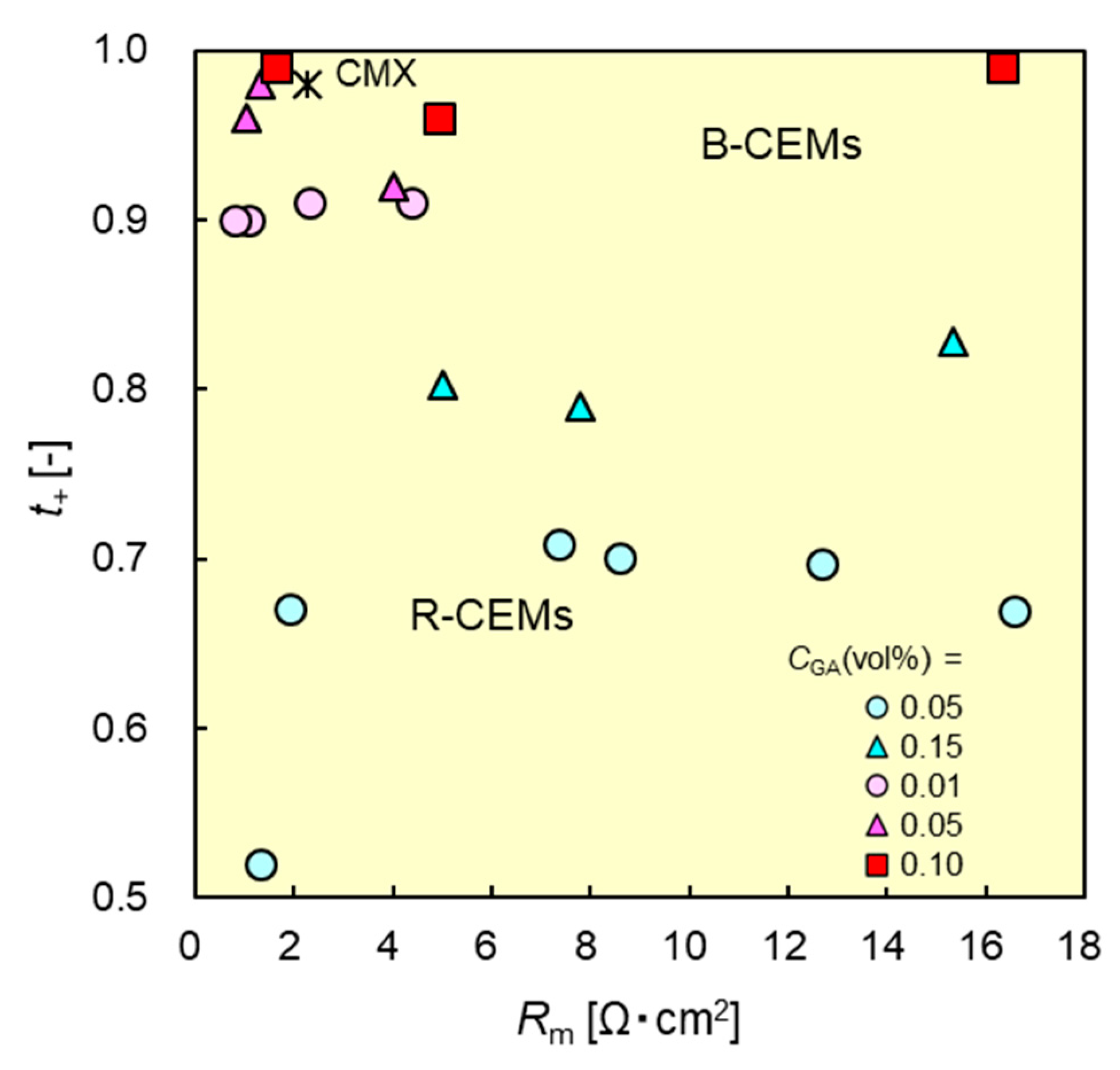
3.6. Relationship between Membrane Resistance and Dynamic State Transport Number

An ion-exchange membrane with both high ion permselectivity and low membrane resistance is desirable in IEM applications such as electrodialysis (ED), reverse electrodialysis (RED), fuel cells, and redox flow batteries. Figure 9 shows the relationship between the dynamic state transport numbers and the resistances of the CEMs. The CEM located at the upper left-hand side of the figure exhibited high performance in the aforementioned applications. B-CEMs typically exhibited higher transport numbers than R-CEMs with similar membrane resistances. For example, B-CEM-9 with a resistance of 1.6 Ωcm2 exhibited a transport number of 0.99, whereas that of the R-CEM with almost the same resistance (1.9 Ωcm2) was 0.67; thus, the transport number of the B-CEM was approximately 48% higher than that of the R-CEM, although both CEMs had similar membrane resistances. The dynamic transport number and membrane resistance of B-CEM-9 were 0.99 and 1.6 Ω cm2, respectively, whereas those of CMX were 0.98 and 2.3 Ω cm2, respectively. The B-CEM prepared herein had almost the same dynamic transport number, whereas its membrane resistance was 70% that of the commercially available CEM.

3.7. Mechanical Strength of B-CEMs

The mechanical properties of the B-CEMs are listed in Table 3. Here, B-CEM-12 was too brittle to measure its mechanical strength. The tensile strengths of the B-CEMs were lower than that of the CMX membrane, because the B-CEMs did not have any support materials, whereas the commercial ion-exchange membranes were supported by materials such as PVC cloth [42]. Hence, PVA-based CEMs fabricated with support materials are expected to have sufficient mechanical strength for application in electrodialysis desalination processes at low salt concentrations.

4. Conclusions

In this study, CEMs with IPN structures were fabricated from a PVA-based block copolymer—PVA-b-PSSS—containing various molar percentages of cation-exchange groups, followed by crosslinking with various concentrations of crosslinking agent. The B-CEMs thus obtained had lower water content than R-CEMs with the same molar percentages of cation-exchange groups.
The charge densities of the membranes increased with increasing CCEG and increasing CGA. A maximum charge density of 1.47 mol/dm3 was obtained with B-CEM-3 (CCEG = 2.9 mol%; CGA = 0.10 vol.%), which was almost two-thirds of the charge density of CMX—a commercially available CEM.
The B-CEMs exhibited higher transport numbers than the R-CEMs with similar membrane resistances. The dynamic transport number and membrane resistance of B-CEM-9 (CCEG = 8.3 mol%; CGA = 0.10 vol.%) were 0.99 and 1.6 Ωcm2, respectively, whereas those of CMX were 0.98 and 2.3 Ωcm2, respectively.
Optimization of the molar ratio of the cation-exchange groups to vinyl alcohol groups, and of the physical and chemical crosslinking conditions, (particularly the annealing temperature and crosslinker concentration), reduced the membrane resistance of PVA-based CEMs. With high counter-ion permselectivities and low membrane resistances, the developed PVA-based CEMs exhibit a similar performance in ED and RED processes to that of commercially available CEMs. Furthermore, the PVA-based block copolymer can prepare a self-standing ion-exchange layer, indicating that the ion-exchange layer has higher mechanical strength than the ion-exchange domain of styrene-divinylbenzene-based matrix that is used in commercial IEMs. Therefore, a PVA-based CEM can be manufactured by coating the polymer solution on non-woven fabric support. The CEMs manufactured in the process can potentially have a lower cost than commercial CEMs, and are thus expected to be even more cost-effective and efficient in applications involving ED and RED systems.

5. Research Highlights

Block-type, PVA-based cation-exchange membranes (B-CEMs) were prepared.
The transport numbers of B-CEMs were higher than those of R-CEMs.
B-CEMs exhibit similar transport numbers to a commercial CEM.

Author Contributions

In this study, Y.K. performed experiments, analysis the data, and wrote the manuscript. N.A.H. worked on draft and revise the manuscript. T.M. performed experiments and analysis the data, M.A. performed experiments and analysis the data, M.H. supervised the project, lead the group, revised the manuscript and analysis the data. All authors have read and agreed to the published version of the manuscript.

Funding

This study was partly supported by JSPS KAKENHI Grant Number JP16H01796 and JP21H04942, and the Salt Science Research Foundation (No. 0612, 0709, and 0810).

Institutional Review Board Statement

Not applicable.

Data Availability Statement

All data generated or analysed during this study are included in this published article.

Conflicts of Interest

The authors declare no conflict of interest.

References

  1. Sata, T. Ion Exchange Membranes, Preparation, Characterization, Modification and Application; Royal Society of Chemistry: London, UK, 2004. [Google Scholar]
  2. Nemati, M.; Hosseini, S.M.; Shabanian, M. Novel electrodialysis cation exchange membrane prepared by 2-acrylamido-2-methylpropane sulfonic acid; heavy metal ions removal. J. Hazard. Mater. 2017, 337, 90–104. [Google Scholar] [CrossRef]
  3. Ran, J.; Wu, L.; He, Y.; Yang, Z.; Wang, Y.; Jiang, C.; Ge, L.; Bakangura, E.; Xu, T. Ion exchange membranes: Newdevelopments and applications. J. Membr. Sci. 2017, 522, 267–291. [Google Scholar] [CrossRef]
  4. Lee, C.H.; Park, H.B.; Chung, Y.S.; Lee, Y.M.; Freeman, B.D. Water sorption, proton conduction, and methanol permeation properties of sulfonated polyimide membranes cross-linked with N,N-bis(2-hydroxyethyl)-2-aminoethanesulfonic acid (BES). Macromolecules 2006, 39, 755–764. [Google Scholar] [CrossRef]
  5. Chen, K.; Hu, Z.; Endo, N.; Fang, J.; Higa, M.; Okamoto, K. Sulfonated polyimides bearing benzimidazole groups for direct methanol fuel cell applications. J. Membr. Sci. 2010, 351, 214–221. [Google Scholar] [CrossRef]
  6. Peighambardoust, S.J.; Rowshanzamir, S.; Amjadi, M. Review of the proton exchange membranes for fuel cell applications. Int. J. Hydrogen Energy 2010, 35, 9349–9384. [Google Scholar] [CrossRef]
  7. Gottesfeld, S.; Dekel, D.R.; Page, M.; Bae, C.; Yan, Y.; Zelenay, P.; Kim, Y.S. Anion exchange membrane fuel cells: Current status and remaining challenges. J. Power Sources 2018, 375, 170–184. [Google Scholar] [CrossRef]
  8. Miyake, J.; Ogawa, Y.; Tanaka, T.; Ahn, J.; Oka, K.; Oyaizu, K.; Miyatake, K. Rechargeable proton exchange membrane fuel cell containing an intrinsic hydrogen storage polymer. Commun. Chem. 2020, 3, 138. [Google Scholar] [CrossRef]
  9. Jang, J.; Kim, D.-H.; Kang, B.; Lee, J.-H.; Pak, C.; Lee, J.-S. Impact of N-substituent and pKa of azole rings on fuel cell performance and phosphoric acid loss. Appl. Mater. Interfaces 2021, 13, 531–540. [Google Scholar] [CrossRef]
  10. Hana, L.; Liua, Y.; Chew, J.W. Boron transfer during desalination by electrodialysis. J. Membr. Sci. 2018, 522, 64–72. [Google Scholar] [CrossRef]
  11. Li, X.; Zhang, H.; Mai, Z.; Zhang, H.; Vankelecom, I. Ion exchange membranes for vanadium redox flow battery (VRB) applications. Energy Environ. Sci. 2011, 4, 1147–1160. [Google Scholar] [CrossRef]
  12. Gubler, L. Membranes and separators for redox flow batteries. Curr. Opin. Electrochem. 2019, 18, 31–36. [Google Scholar] [CrossRef]
  13. Xue, R.; Jiang, F.; Wang, F.; Zhou, X. Towards cost-effective proton-exchange membranes for redox flow batteries: A facile and innovative method. J. Power Sources 2020, 449, 227475. [Google Scholar] [CrossRef]
  14. Tedesco, M.; Scalici, C.; Vaccari, D.; Cipollina, A.; Tamburini, A.; Micale, G. Performance of the first reverse electrodialysis pilot plant for power production from saline waters and concentrated brines. J. Membr. Sci. 2016, 500, 33–45. [Google Scholar] [CrossRef] [Green Version]
  15. Nam, J.-Y.; Hwang, K.-S.; Kim, H.-C.; Jeong, H.; Kim, H.; Jwa, E.; Yang, S.; Choi, J.; Kim, C.-S.; Han, J.-H.; et al. Assessing the behavior of the feed-water constituents of a pilot-scale 1000-cell-pair reverse electrodialysis with seawater and municipal wastewater effluent. Water Res. 2019, 148, 261–271. [Google Scholar] [CrossRef] [PubMed]
  16. Mehdizadeh, S.; Kakihana, Y.; Abo, T.; Yuan, Q.; Higa, M. Power generation performance of a pilot-scale reverse electrodialysis using monovalent selective ion-exchange membranes. Membranes 2021, 11, 27. [Google Scholar] [CrossRef]
  17. Kasahara, S.; Kubo, S.; Onuki, K.; Nomura, M. Thermal efficiency evaluation of HI synthesis/concentration procedures in the thermochemical water splitting IS process. Int. J. Hydrogen Energy 2004, 29, 579–587. [Google Scholar] [CrossRef]
  18. Kasahara, S.; Kubo, S.; Hino, R.; Onuki, K.; Nomura, M.; Nakao, S. Flowsheet study of the thermochemical water-splitting iodine–sulfur process for effective hydrogen production. Int. J. Hydrogen Energy 2007, 32, 489–496. [Google Scholar] [CrossRef]
  19. Tanaka, N.; Sawada, S.; Yamaki, T.; Kodaira, T.; Kimura, T.; Nomura, M. Improvement of HI concentration performance for hydrogen production iodine–sulfur process using crosslinked cation-exchange membrane. Chem. Eng. Sci. 2021, 237, 116575. [Google Scholar] [CrossRef]
  20. Choi, E.Y.; Bae, B.; Moon, S.H. Control of the fixed charge distribution in an ion exchange membrane via diffusion and the reaction rate of the monomer. J. Phys. Chem. B 2007, 111, 6383–6390. [Google Scholar] [CrossRef]
  21. Asari, Y.; Shoji, N.; Miyoshi, K.; Umeno, D.; Saito, K. Electrodialysis of sulfuric acid with cation-exchange membranes prepared by electro-beam-induced graft polymerization. J. Ion Exch. 2011, 22, 53–57. [Google Scholar] [CrossRef] [Green Version]
  22. Higa, M.; Goto, M.; Yamaki, T.; Sawada, S.; Koshikawa, H.; Kitamura, A. Characterization of cation-exchange membranes prepared by ion-track graft polymerization. Bull. Soc. Sea Water Sci. Jpn. 2017, 71, 37–38. [Google Scholar]
  23. Qin, X.H.; Wang, S.Y. Filtration properties of electrospinning nanofibers. J. Appl. Polym. Sci. 2006, 102, 1285–1290. [Google Scholar] [CrossRef]
  24. Dai, X.S.; Shivkumar, S. Electrospinning of hydroxyapatite fibrous Mats. Mater. Lett. 2007, 61, 2735–2738. [Google Scholar] [CrossRef]
  25. Yang, E.; Qin, X.; Wang, S. Electrospun crosslinked polyvinyl alcohol membrane. Mater. Lett. 2008, 62, 3555–3557. [Google Scholar] [CrossRef]
  26. Seino, F.; Konosu, Y.; Ashizawa, M.; Kakihana, Y.; Higa, M.; Matsumoto, H. Polyelectrolyte composite membranes containing electrospun ion-exchange nanofibers: Effect of nanofiber surface charges on ionic transport. Langmuir 2018, 34, 13035–13040. [Google Scholar] [CrossRef] [PubMed]
  27. Yang, T. Preliminary study of SPEEK/PVA blend membranes for DMFC applications. Int. J. Hydrogen Energy 2008, 33, 6772–6779. [Google Scholar] [CrossRef]
  28. Yang, T. Poly(vinyl alcohol)/sulfated β-cyclodextrin for direct methanol fuel cell applications. Int. J. Hydrogen Energy 2009, 4, 6917–6924. [Google Scholar] [CrossRef]
  29. Yang, C.-C.; Chien, W.-C.; Li, Y.J. Direct methanol fuel cell based on poly(vinyl alcohol)/titanium oxide nanotubes/poly(styrene sulfonic acid) (PVA/nt-TiO2/PSSA) composite polymer membrane. J. Power Sources 2010, 195, 3407–3415. [Google Scholar] [CrossRef]
  30. Higa, M.; Sugita, M.; Maesowa, S.; Endo, N. Poly(vinyl alcohol)-based polymer electrolyte membranes for direct methanol fuel cells. Electrochim. Acta 2010, 55, 1445–1449. [Google Scholar] [CrossRef]
  31. Yang, C.-C. Fabrication and characterization of poly(vinyl alcohol)/montmorillonite/poly(styrene sulfonic acid) proton-conducting composite membranes for direct methanol fuel cells. Int. J. Hydrogen Energy 2011, 34, 4419–4431. [Google Scholar] [CrossRef]
  32. Liu, C.-P.; Dai, C.-A.; Chao, C.-Y.; Chang, S.-J. Novel proton exchange membrane based on crosslinked poly(vinyl alcohol) for direct methanol fuel cells. J. Power Sources 2014, 249, 285–298. [Google Scholar] [CrossRef]
  33. Higa, M.; Feng, S.; Endo, N.; Kakihana, Y. Characteristics and direct methanol fuel cell performance of polymer electrolyte membranes prepared from poly(vinyl alcohol-b-styrene sulfonic acid). Electrochim. Acta 2015, 153, 83–89. [Google Scholar] [CrossRef]
  34. Dong, F.; Xu, S.; Wu, Xi.; Jin, D.; Wang, P.; Wu, D.; Leng, Q. Cross-linked poly(vinyl alcohol)/sulfosuccinic acid (PVA/SSA) as cation exchange membranes for reverse electrodialysis. Sep. Purif. Technol. 2021, 267, 118629. [Google Scholar]
  35. Higa, M.; Yamakawa, T. Design and preparation of a novel temperature-responsive ionic gel. 1. A fast and reversible temperature response in the charge density. J. Phys. Chem. B 2004, 108, 16703–16707. [Google Scholar]
  36. Yamakawa, T.; Ishida, S.; Higa, M. Transport properties of ions through temperature-responsive charged membranes prepared using poly(vinyl alcohol)/ poly(N-isopropylacrylamide)/poly(vinylalcohol-co-2-acrylamido-2-methylpropane sulfonic acid). J. Membr. Sci. 2005, 250, 61–68. [Google Scholar] [CrossRef]
  37. Nishimura, M.; Shimizu, E.; Higa, M. Electrodialytic transport properties of cation exchange membranes prepared from poly(vinyl alcohol) and poly(vinyl alcohol-co-2-acrylamido-2-methylpropane sulfonic acid). Desalin. Water Treat. 2010, 17, 255–261. [Google Scholar] [CrossRef] [Green Version]
  38. Higa, M.; Mehdizadeh, S.; Feng, S.; Endo, N.; Kakihana, Y. Cell performance of direct methanol alkaline fuel cell (DMAFC) using anion exchange membranes prepared from PVA-Based block copolymer. J. Membr. Sci. 2020, 597, 117618. [Google Scholar] [CrossRef]
  39. Kuraray Co., Ltd. Vinyl Alchol-Based Graft Polymer, Method for Producing Same, And Ion-Exchange Membrane Using Same. Japan Patent WO2014087981 A1, 12 June 2014. [Google Scholar]
  40. Brandrup, J.; Immergeut, E.H.; Grulke, E.A. Polymer Handbook, 4th ed.; Wiley-Interscience: Hoboken, NJ, USA, 1999; p. VI-14. [Google Scholar]
  41. Nishimura, M.; Higa, M.; Akamine, K.; Masudaya, S. Preparation and characterization of anion-exchange membranes with a semi-interpenetrating network structure of poly(vinyl alcohol) and poly(allyl amine). Desalination 2008, 233, 157–165. [Google Scholar] [CrossRef]
  42. Higa, M.; Tanaka, N.; Nagase, M.; Yutani, K.; Kameyama, T.; Takamura, K.; Kakihana, Y. Electrodialytic properties of aromatic and aliphatic type hydrocarbon-based anion-exchange membranes with various anion-exchange groups. Polymer 2014, 55, 3951–3960. [Google Scholar] [CrossRef]
Figure 1. Chemical structure of SH end group PVA, SSA, and PVA-b-PSSS, and reaction scheme of PVA-b-PSSS.
Membranes 11 00452 g001
Figure 2. Apparatus for the electrodialysis experiments. The effective area of the cell was 4.0 cm2.
Membranes 11 00452 g002
Figure 3. 1H NMR spectra of (a) PVA-SH, (b) SSS monomer, and (c) PVA-b-PSSS graft copolymer in DMSO-d6.
Membranes 11 00452 g003
Figure 4. Photograph of one of the prepared B-CEMs.
Membranes 11 00452 g004
Figure 5. Water contents H of B-CEMs and R-CEMs as functions of content C CEG of cation-exchange groups in copolymers. Red and blue symbols denote the data of B-CEMs and R-CEMs, respectively.
Membranes 11 00452 g005
Figure 6. Charge densities Cx of B-CEMs and R-CEMs as functions of contents C CEG of cation-exchange groups in copolymers. Red and blue symbols denote the data of B-CEMs and R-CEMs, respectively.
Membranes 11 00452 g006
Figure 7. Membrane resistances Rm of B-CEMs and R-CEMs as functions of water content H. Red and blue symbols denote the data of B-CEMs and R-CEMs, respectively.
Membranes 11 00452 g007
Figure 8. Dynamic state transport numbers t+ of B-CEMs and R-CEMs vs. C CEG of cation-exchange groups in copolymers. Red and blue symbols denote the data of B-CEMs and R-CEMs, respectively.
Membranes 11 00452 g008
Figure 9. Relationship between dynamic state transport numbers td+ and membrane resistance Rm of B-CEMs and R-CEMs. Red and blue symbols denote the data of B-CEMs and R-CEMs, respectively. *: The data of the commercial CEM (CMX).
Membranes 11 00452 g009
Table 1. Reaction conditions of PVA-b-PSSS block copolymers.
SamplePVA
[g]
SSS
[g]
H2O
[g]
V-50
[g]
CmSSS [mol%]CCEG
[mol%]
PVA-b-PSSS-135.68.002300.1442.91
PVA-b-PSSS-235.613.02500.2275.66
PVA-b-PSSS-335.620.02730.34108.25
PVA-b-PSSS-428.520.82320.351310.7
V-50: polymerization initiator; CmSSS: SSS content in reaction mixture; CCEG: the cation-exchange group content in the obtained copolymer.
Table 2. Cation-exchange group contents CCEG, GA concentrations CGA for different preparation conditions, thicknesses dW of the wet membranes, water content H, and ion-exchange capacities IEC of B-CEMs.
SampleCCEG [mol%]CGA
[vol. %]
dW
[µm]
H
[-]
IEC
[meq/g]
B-CEM-12.910.01760.520.56
B-CEM-20.05820.43
B-CEM-30.10720.41
B-CEM-45.660.01970.550.79
B-CEM-50.05920.47
B-CEM-60.10900.44
B-CEM-78.250.01890.561.05
B-CEM-80.05850.53
B-CEM-90.101120.50
B-CEM-1010.70.011090.571.38
B-CEM-110.051190.56
B-CEM-120.101010.54
Table 3. Maximum tensile strengths (TS), Young’s moduli (YM), and elongations at breaking point (E) of B-CEMs and CMX (a commercial CEM). The properties of B-CEM-12 could not be measured, owing to its brittleness.
SampleTS
[MPa]
YM
[MPa]
E
[%]
B-CEM-14.9828.217.7
B-CEM-21.4846.34.98
B-CEM-35.1474.41.66
B-CEM-43.5877.911.0
B-CEM-52.1039.22.18
B-CEM-64.6371.02.24
B-CEM-73.8663.610.9
B-CEM-86.1350.74.90
B-CEM-92.3835.63.07
B-CEM-102.336.438.80
B-CEM-117.7541.73.57
B-CEM-12---
CMX36.7112014.1
Publisher’s Note: MDPI stays neutral with regard to jurisdictional claims in published maps and institutional affiliations.

