Effect of PAC on the Behavior of Dynamic Membrane Bioreactor Filtration Layer Based on the Analysis of Mixed Liquid Properties and Model Fitting


Abstract
:
1. Introduction
2. Materials and Methods
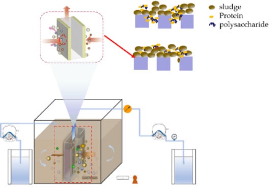
2.1. Operation of DMBR
2.2. Analytical Methods
2.2.1. Filtration Resistance Analysis
2.2.2. Extraction and Analysis of EPS, SMP (Soluble Microbial Products)
2.2.3. SEM Analysis
2.2.4. Other Terms Analysis
2.2.5. Data Analysis
3. Results
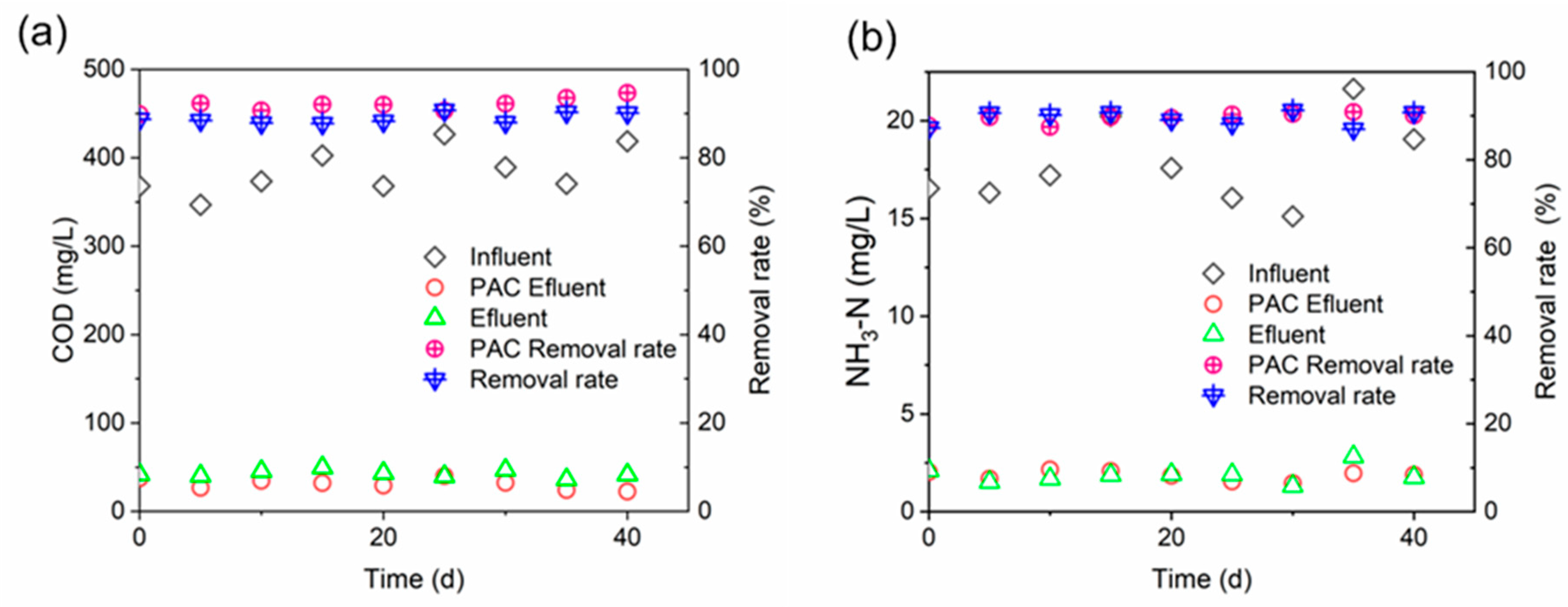
3.1. Filtration Performance
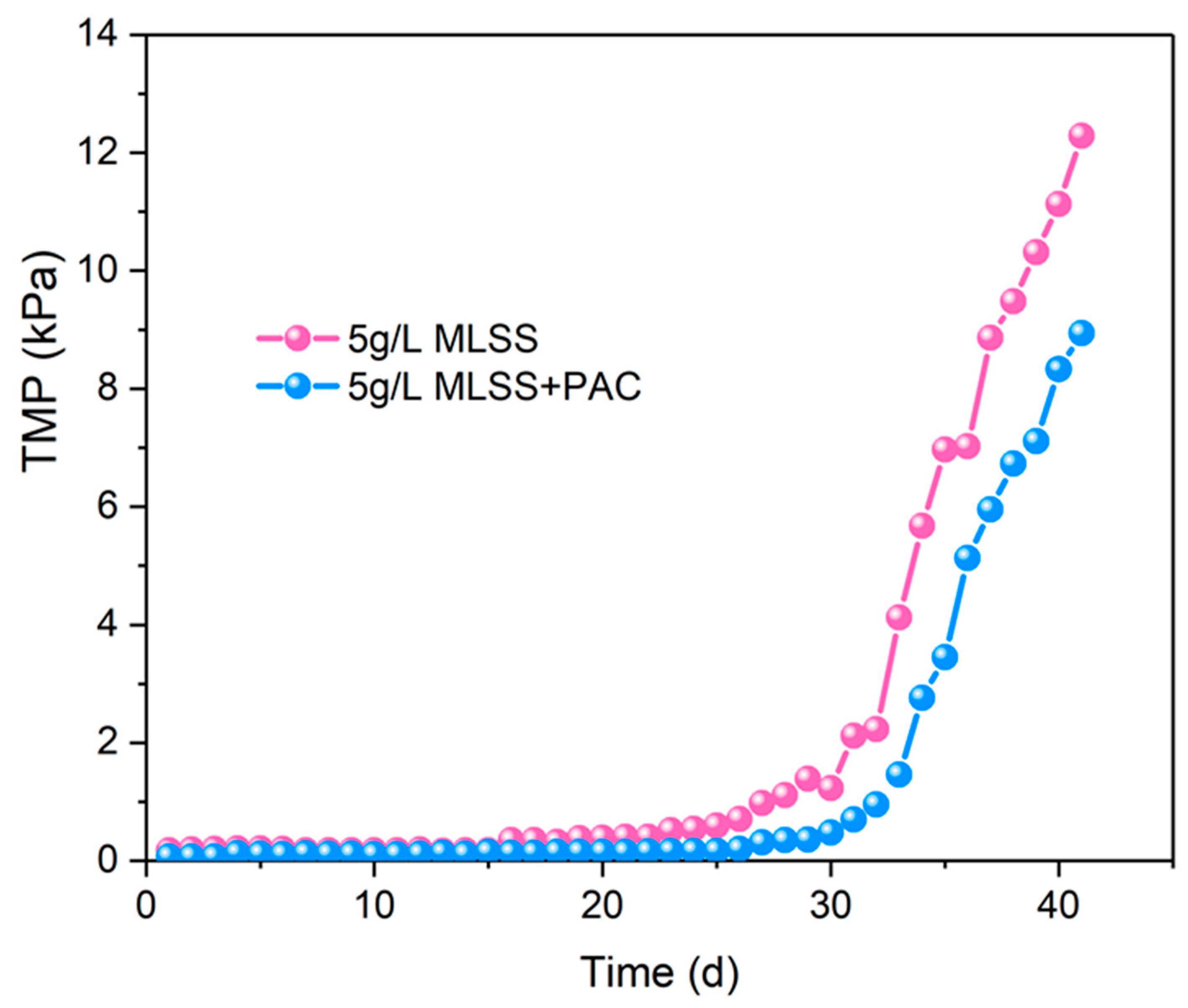
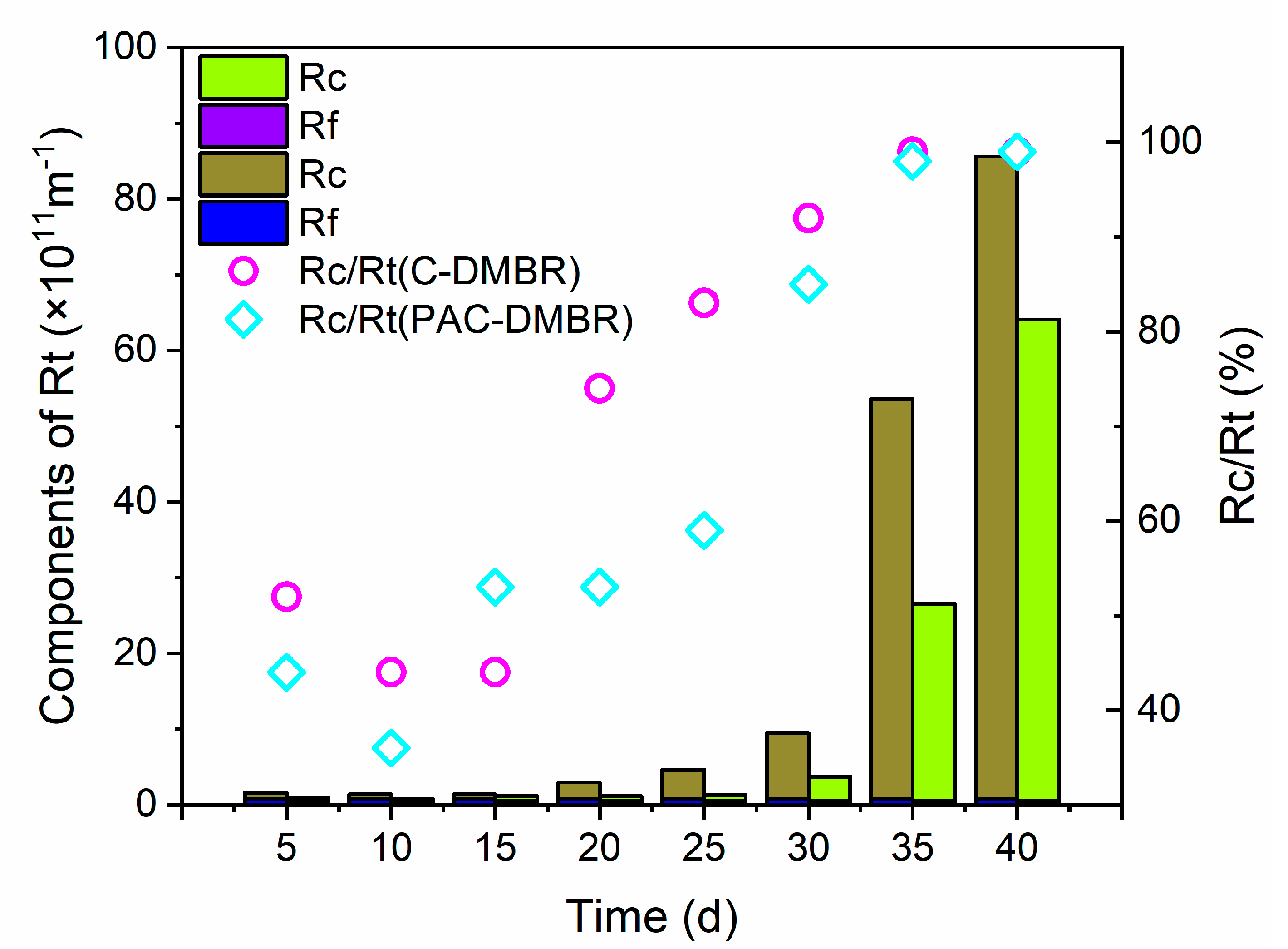
3.2. Membrane Resistance Analysis
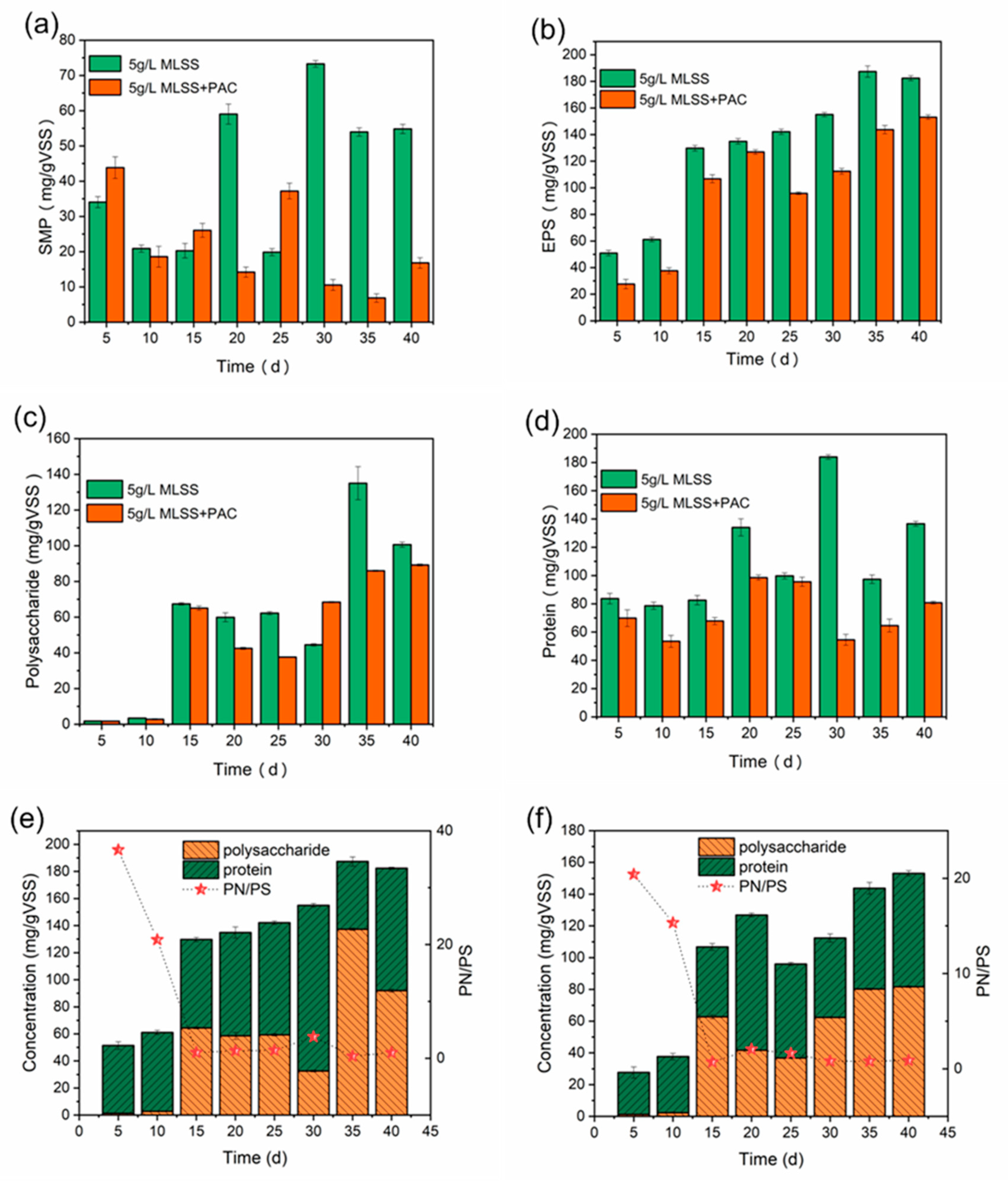
3.3. EPS and SMP Analysis of Samples
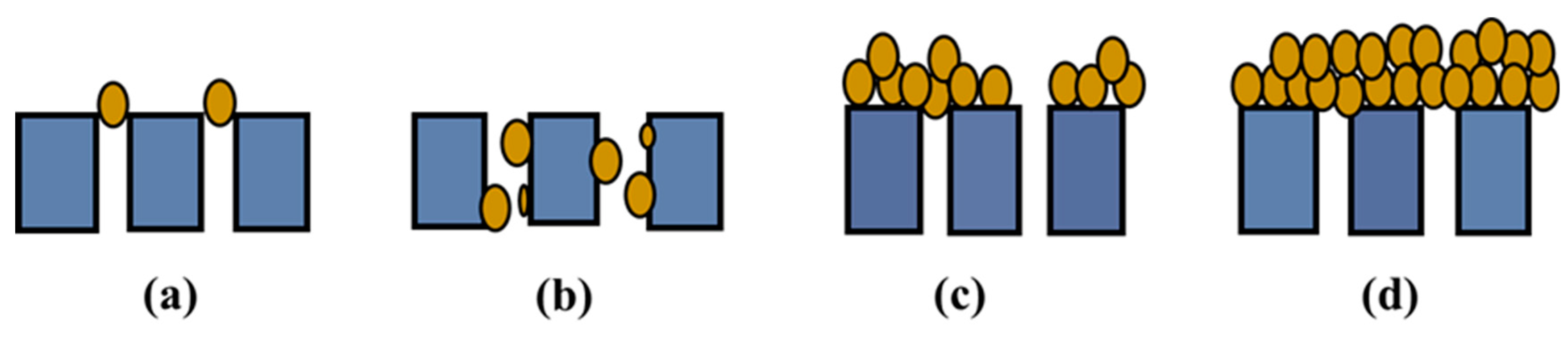
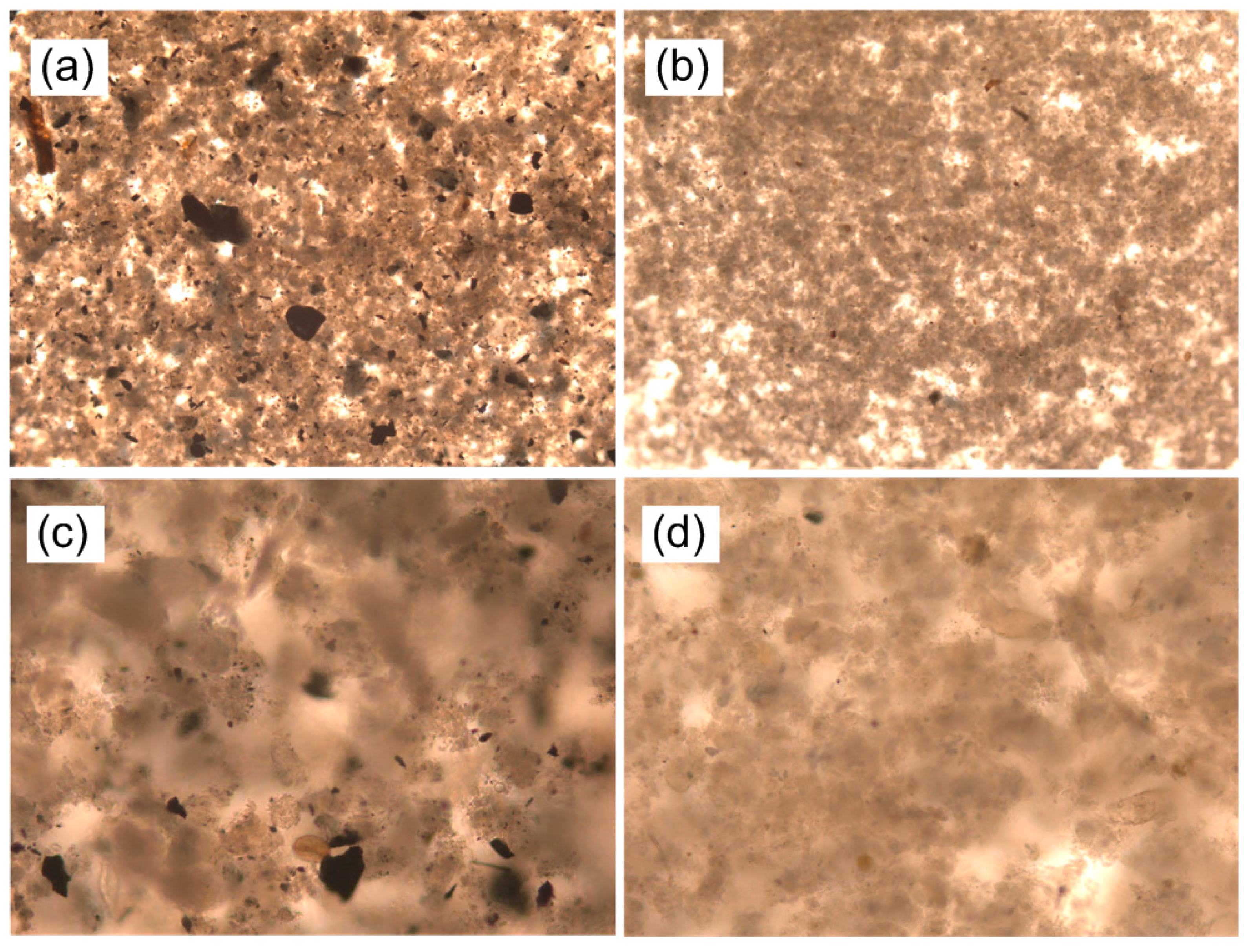
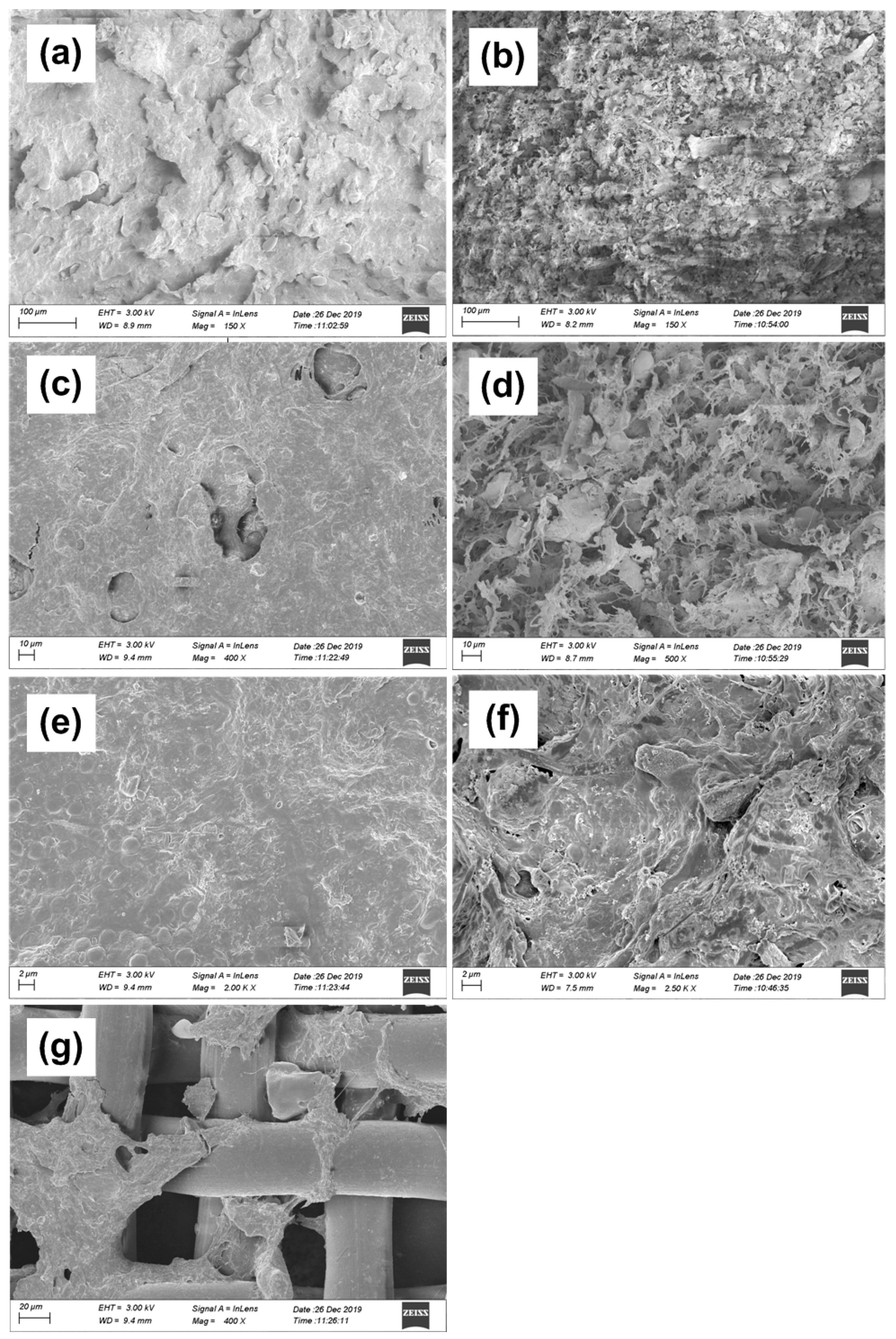
3.4. SEM Analysis of Filtration Cake
4. Conclusions
Author Contributions
Funding
Conflicts of Interest
Abbreviations
| MBR | Membrane Bioreactor |
| DMBR | Dynamic Membrane Bioreactor |
| HRT | Hydraulic Retention Time |
| DM | Dynamic Membrane |
| COD | Chemical Oxygen Demand |
| PS | Polysaccharide |
| EPS | Extracellular Polymer Substances |
| SMP | Soluble Microbial Products |
| PAC | Powder Activated Carbon |
| TMP | Transmembrane Pressure |
| PN | Protein |
References
- Tan, X.; Acquah, I.; Liu, H.; Li, W.; Tan, S. A critical review on saline wastewater treatment by membrane bioreactor (MBR) from a microbial perspective. Chemosphere 2019, 220, 1150–1162. [Google Scholar] [CrossRef]
- Fatone, F.; Di Fabio, S.; Bolzonella, D.; Cecchi, F. Fate of aromatic hydrocarbons in Italian municipal wastewater systems: An overview of wastewater treatment using conventional activated-sludge processes (CASP) and membrane bioreactors (MBRs). Water Res. 2011, 45, 93–104. [Google Scholar] [CrossRef] [PubMed]
- Deowan, S.A.; Galiano, F.; Hoinkis, J.; Johnson, D.; Altinkaya, S.A.; Gabriele, B.; Hilal, N.; Drioli, E.; Figoli, A. Novel low-fouling membrane bioreactor (MBR) for industrial wastewater treatment. J. Membr. Sci. 2016, 510, 524–532. [Google Scholar] [CrossRef] [Green Version]
- Andrade, L.; Mendes, F.D.D.S.; Espindola, J.C.; Amaral, M.C.S. Internal versus external submerged membrane bioreactor configurations for dairy wastewater treatment. Desalination Water Treat. 2013, 52, 2920–2932. [Google Scholar] [CrossRef]
- Sathya, U.; Keerthi; Nithya, M.; Balasubramanian, N. Evaluation of advanced oxidation processes (AOPs) integrated membrane bioreactor (MBR) for the real textile wastewater treatment. J. Environ. Manag. 2019, 246, 768–775. [Google Scholar] [CrossRef]
- Mahat, S.B.; Omar, R.; Idris, A.; Kamal, S.M.M.; Idris, A.I.M. Dynamic membrane applications in anaerobic and aerobic digestion for industrial wastewater: A mini review. Food Bioprod. Process. 2018, 112, 150–168. [Google Scholar] [CrossRef]
- Lin, H.; Peng, W.; Zhang, M.; Cheng, J.; Hong, H.; Zhang, Y. A review on anaerobic membrane bioreactors: Applications, membrane fouling and future perspectives. Desalination 2013, 314, 169–188. [Google Scholar] [CrossRef]
- Zhu, Y.; Cao, L.; Wang, Y. Characteristics of a self-forming dynamic membrane coupled with a bioreactor in application of anammox processes. Environ. Sci. Technol. 2019, 53, 13158–13167. [Google Scholar] [CrossRef]
- Ersahin, M.E.; Ozgun, H.; Dereli, R.K.; Öztürk, I.; Roest, K.; Van Lier, J.B. A review on dynamic membrane filtration: Materials, applications and future perspectives. Bioresour. Technol. 2012, 122, 196–206. [Google Scholar] [CrossRef]
- Yeon, K.M.; Cheong, W.S.; Oh, H.S.; Lee, W.N.; Hwang, B.K.; Lee, C.H.; Beyenal, H.; Lewandowski, Z. Quorum sensing: A new biofouling control paradigm in a membrane bioreactor for advanced wastewater treatment. Environ. Sci. Technol. 2009, 43, 380–385. [Google Scholar] [CrossRef]
- Fan, B.; Huang, X. Characteristics of a self-forming dynamic membrane coupled with a bioreactor for municipal wastewater treatment. Environ. Sci. Technol. 2002, 36, 5245–5251. [Google Scholar] [CrossRef] [PubMed]
- Ye, M.; Zhang, H.; Wei, Q.; Lei, H.; Yang, F.; Zhang, X. Study on the suitable thickness of a PAC-precoated dynamic membrane coupled with a bioreactor for municipal wastewater treatment. Desalination 2006, 194, 108–120. [Google Scholar] [CrossRef]
- Hu, Y.; Wang, X.C.; Tian, W.; Ngo, H.H.; Chen, R. Towards stable operation of a dynamic membrane bioreactor (DMBR): Operational process, behavior and retention effect of dynamic membrane. J. Membr. Sci. 2016, 498, 20–29. [Google Scholar] [CrossRef]
- Wang, Y.-K.; Sheng, G.-P.; Li, W.-W.; Yu, H.-Q. A pilot investigation into membrane bioreactor using mesh filter for treating low-strength municipal wastewater. Bioresour. Technol. 2012, 122, 17–21. [Google Scholar] [CrossRef]
- Chu, L.; Li, S. Filtration capability and operational characteristics of dynamic membrane bioreactor for municipal wastewater treatment. Sep. Purif. Technol. 2006, 51, 173–179. [Google Scholar] [CrossRef]
- Chu, H.; Zhang, Y.; Zhou, X.; Zhao, Y.; Dong, B.; Zhang, H. Dynamic membrane bioreactor for wastewater treatment: Operation, critical flux, and dynamic membrane structure. J. Membr. Sci. 2014, 450, 265–271. [Google Scholar] [CrossRef]
- Li, C.T.; Liu, H.J.; Qian, X.Z.; Yang, H.H. Effect of hydrophilic foamed copper on dynamic membrane formation in dynamic membrane bioreactor (DMBR). In Proceedings of the 3rd International Conference on Water Resource and Environment (WRE 2017), Qingdao, China, 26–29 June 2017. [Google Scholar]
- Zhang, X.; Wang, Z.; Wu, Z.; Wei, T.; Lu, F.; Tong, J.; Mai, S. Membrane fouling in an anaerobic dynamic membrane bioreactor (AnDMBR) for municipal wastewater treatment: Characteristics of membrane foulants and bulk sludge. Process. Biochem. 2011, 46, 1538–1544. [Google Scholar] [CrossRef]
- Wang, Z.; Cao, J.; Meng, F. Interactions between protein-like and humic-like components in dissolved organic matter revealed by fluorescence quenching. Water Res. 2015, 68, 404–413. [Google Scholar] [CrossRef]
- Shao, S.; Fu, W.; Li, X.; Shi, D.; Jiang, Y.; Li, J.; Gong, T.; Li, X. Membrane fouling by the aggregations formed from oppositely charged organic foulants. Water Res. 2019, 159, 95–101. [Google Scholar] [CrossRef]
- Sagbo, O.; Sun, Y.; Hao, A.; Gu, P. Effect of PAC addition on MBR process for drinking water treatment. Sep. Purif. Technol. 2008, 58, 320–327. [Google Scholar] [CrossRef]
- Hu, J.; Shang, R.; Deng, H.; Heijman, S.G.; Rietveld, L.C. Effect of PAC dosage in a pilot-scale PAC–MBR treating micro-polluted surface water. Bioresour. Technol. 2014, 154, 290–296. [Google Scholar] [CrossRef] [PubMed]
- Dong, Q.; Parker, W.; Dagnew, M. Impact of FeCl3 dosing on AnMBR treatment of municipal wastewater. Water Res. 2015, 80, 281–293. [Google Scholar] [CrossRef] [PubMed]
- Satyawali, Y.; Balakrishnan, M. Performance enhancement with powdered activated carbon (PAC) addition in a membrane bioreactor (MBR) treating distillery effluent. J. Hazard. Mater. 2009, 170, 457–465. [Google Scholar] [CrossRef] [PubMed]
- Siddiqui, M.A.; Dai, J.; Guan, D.; Chen, G. Exploration of the formation of self-forming dynamic membrane in an upflow anaerobic sludge blanket reactor. Sep. Purif. Technol. 2019, 212, 757–766. [Google Scholar] [CrossRef]
- Sheng, G.-P.; Yu, H.-Q.; Li, X.-Y. Extracellular polymeric substances (EPS) of microbial aggregates in biological wastewater treatment systems: A review. Biotechnol. Adv. 2010, 28, 882–894. [Google Scholar] [CrossRef]
- Nouha, K.; Kumar, R.S.; Balasubramanian, S.; Tyagi, R.D. Critical review of EPS production, synthesis and composition for sludge flocculation. J. Environ. Sci. 2018, 66, 225–245. [Google Scholar] [CrossRef] [Green Version]
- Liu, H.; Fang, H.H.P. Extraction of extracellular polymeric substances (EPS) of sludges. J. Biotechnol. 2002, 95, 249–256. [Google Scholar] [CrossRef]
- Dubois, M.; Gilles, K.A.; Hamilton, J.K.; Rebers, P.A.; Smith, F. Colorimetric Method for Determination of Sugars and Related Substances. Anal. Chem. 1956, 28, 350–356. [Google Scholar] [CrossRef]
- Frølund, B.; Griebe, T.; Nielsen, P.H. Enzymatic-Activity in the Activated-Sludge Floc Matrix. Appl. Microbiol. Biotechnol. 1995, 43, 755–761. [Google Scholar] [CrossRef]
- Xu, C.; Wang, X.; Dou, X.; Gao, B. Coagulation-dynamic membrane filtration process at constant flow rate for treating polluted river water. Desalination Water Treat. 2014, 52, 102–110. [Google Scholar] [CrossRef]
- Saleem, M.; Alibardi, L.; Cossu, R.; Lavagnolo, M.C.; Spagni, A. Analysis of fouling development under dynamic membrane filtration operation. Chem. Eng. J. 2017, 312, 136–143. [Google Scholar] [CrossRef]
- Bolton, G.; Lacasse, D.; Kuriyel, R. Combined models of membrane fouling: Development and application to microfiltration and ultrafiltration of biological fluids. J. Membr. Sci. 2006, 277, 75–84. [Google Scholar] [CrossRef]
- Gao, Y.; Ma, D.; Yue, Q.; Gao, B.; Huang, X. Effect of powdered activated carbon (PAC) on MBR performance and effluent trihalomethane formation: At the initial stage of PAC addition. Bioresour. Technol. 2016, 216, 838–844. [Google Scholar] [CrossRef] [PubMed]
- Orshansky, F.; Narkis, N. Characteristics of organics removal by PACT simultaneous adsorption and biodegradation. Water Res. 1997, 31, 391–398. [Google Scholar] [CrossRef]
- Xiaojian, Z.; Zhansheng, W.; Xiasheng, G. Simple combination of biodegradation and carbon adsorption—the mechanism of the biological activated carbon process. Water Res. 1991, 25, 165–172. [Google Scholar] [CrossRef]
- Wang, H.; Qu, F.; Ding, A.; Liang, H.; Jia, R.; Li, K.; Bai, L.; Chang, H.; Li, G. Combined effects of PAC adsorption and in situ chlorination on membrane fouling in a pilot-scale coagulation and ultrafiltration process. Chem. Eng. J. 2016, 283, 1374–1383. [Google Scholar] [CrossRef]
- Cho, B.; Fane, A.G. Fouling transients in nominally sub-critical flux operation of a membrane bioreactor. J. Membr. Sci. 2002, 209, 391–403. [Google Scholar] [CrossRef]
- Williams, M.D.; Pirbazari, M. Membrane bioreactor process for removing biodegradable organic matter from water. Water Res. 2007, 41, 3880–3893. [Google Scholar] [CrossRef]
- Lee, J.; Ahn, W.Y.; Lee, C.H. Comparison of the filtration characteristics between attached and suspended growth microorganisms in submerged membrane bioreactor. Water Res. 2001, 35, 2435–2445. [Google Scholar] [CrossRef]
- Cao, D.W.; Chu, H.; Jin, W.; Dong, B. Characteristics of the biodiatomite dynamic membrane (cake layer) for municipal wastewater treatment. Desalination 2010, 250, 544–547. [Google Scholar] [CrossRef]
- Wang, C.; Chen, W.-N.; Hu, Q.-Y.; Ji, M.; Gao, X. Dynamic fouling behavior and cake layer structure changes in nonwoven membrane bioreactor for bath wastewater treatment. Chem. Eng. J. 2015, 264, 462–469. [Google Scholar] [CrossRef]
- Liao, B.; Allen, D.; Droppo, I.; Leppard, G.; Liss, S. Surface properties of sludge and their role in bioflocculation and settleability. Water Res. 2001, 35, 339–350. [Google Scholar] [CrossRef]
- Massé, A.; Spèrandio, M.; Cabassud, C. Comparison of sludge characteristics and performance of a submerged membrane bioreactor and an activated sludge process at high solids retention time. Water Res. 2006, 40, 2405–2415. [Google Scholar] [CrossRef] [PubMed]
- Wilén, B.-M.; Jin, B.; Lant, P. The influence of key chemical constituents in activated sludge on surface and flocculating properties. Water Res. 2003, 37, 2127–2139. [Google Scholar] [CrossRef]
- Song, J.; Zhang, Z.; Zhang, X. A comparative study of pre-ozonation and in-situ ozonation on mitigation of ceramic UF membrane fouling caused by alginate. J. Membr. Sci. 2017, 538, 50–57. [Google Scholar] [CrossRef]


| Configuration | Plate Membrane |
|---|---|
| Material | Nylon mesh |
| Double-sided effective filtration area | 0.0114 m2 |
| Hydrophilicity | hydrophilic |
| Dacron mesh pore size | 52 μm |
| fabric filter weight | 110 (/cm) |
| Membrane module size | 0.092 m × 0.062 m |
| Model | Equations | Fitted Parameters | |
|---|---|---|---|
| Cake-complete | (3) | Kc(s·m−2), Kb(s−1) | |
| Cake-intermediate | (4) | Kc(s·m−2), Ki(m−1) | |
| Complete-standard | (5) | Kb(s−1), Ks(m−1) | |
| Intermediate- standard | (6) | Ki(m−1), Ks(m−1) | |
| Cake- standard | (7) | Kc(s·m−2), Ks(m−1) | |
| Parameter | C-DMBR | PAC-DMBR |
|---|---|---|
| Zeta Potential | −16.1 ± 0.3 | −11.9 ± 0.4 |
| pH | 7.17 ± 0.14 | 7.06 ± 0.11 |
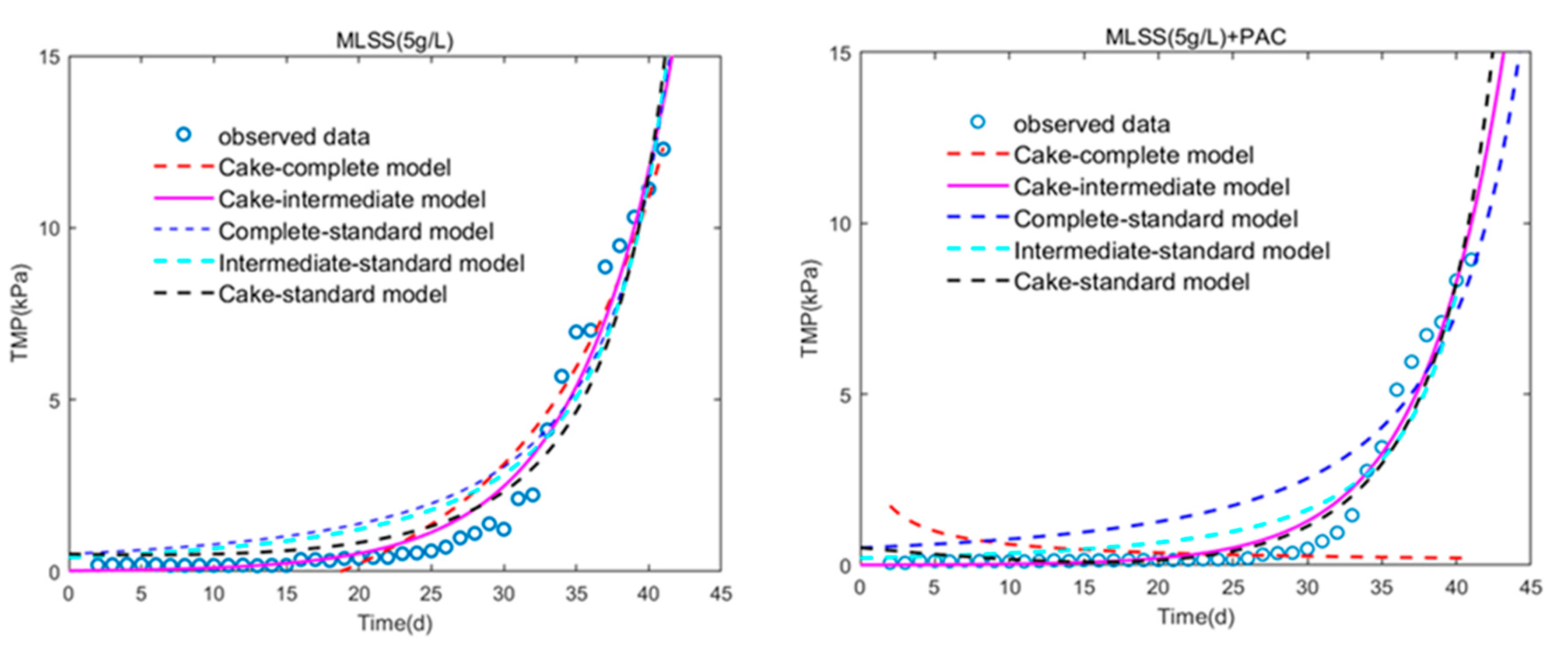
| Model | SSE | R-Squared | Fitting Parameters | ||
|---|---|---|---|---|---|
| Cake-Complete Model | 49.6568 | 0.9008 | Kc Kb | −0.7132 0.0168 | s/m2 s−1 |
| Cake-Intermediate Model | 15.7609 | 0.9659 | Kc Ki | 0.4198 0.1766 | s/m2 m−1 |
| Complete-Standard Model | 44.6724 | 0.9033 | Kb Ks | −0.001707 0.005783 | s−1 m−1 |
| Intermediate-Standard Model | 39.7477 | 0.9140 | Ki Ks | 0.6329 0.4921 | m−1 m−1 |
| Cake-Standard Model | 33.9338 | 0.9322 | Ke Ks | −0.001686 0.006901 | s/m2 m−1 |
Publisher’s Note: MDPI stays neutral with regard to jurisdictional claims in published maps and institutional affiliations. |
© 2020 by the authors. Licensee MDPI, Basel, Switzerland. This article is an open access article distributed under the terms and conditions of the Creative Commons Attribution (CC BY) license (http://creativecommons.org/licenses/by/4.0/).
Share and Cite
Huang, C.; Liu, H.; Meng, S.; Liang, D. Effect of PAC on the Behavior of Dynamic Membrane Bioreactor Filtration Layer Based on the Analysis of Mixed Liquid Properties and Model Fitting. Membranes 2020, 10, 420. https://doi.org/10.3390/membranes10120420
Huang C, Liu H, Meng S, Liang D. Effect of PAC on the Behavior of Dynamic Membrane Bioreactor Filtration Layer Based on the Analysis of Mixed Liquid Properties and Model Fitting. Membranes. 2020; 10(12):420. https://doi.org/10.3390/membranes10120420
Chicago/Turabian StyleHuang, Chunyan, Hongju Liu, Shujuan Meng, and Dawei Liang. 2020. "Effect of PAC on the Behavior of Dynamic Membrane Bioreactor Filtration Layer Based on the Analysis of Mixed Liquid Properties and Model Fitting" Membranes 10, no. 12: 420. https://doi.org/10.3390/membranes10120420