Article

Reduced-Order Model of Rotor Cage in Multiphase Induction Machines: Application on the Prediction of Torque Pulsations

1
Univ. Lille, Arts et Metiers Institute of Technology, Centrale Lille, HEI, L2EP—Laboratoire d’Electrotechnique et d’Electronique de Puissance-ULR2697, HESAM Université, F-59000 Lille, France
2
Institut Vedecom, 23 bis Allée des Marronniers, 78000 Versailles, France
3
Naval Academy Research Institute (IRENav), Ecole Navale, F-29240 Brest, France
*
Author to whom correspondence should be addressed.
Math. Comput. Appl. 2020, 25(1), 11; https://doi.org/10.3390/mca25010011
Submission received: 31 December 2019 / Revised: 23 January 2020 / Accepted: 27 January 2020 / Published: 29 January 2020
(This article belongs to the Special Issue Mathematical Models for the Design of Electrical Machines)

Abstract

:
For three-phase induction machines supplied by sinusoidal current, it is usual to model the n-bar squirrel-cage by an equivalent two-phase circuit. For a multiphase induction machine which can be supplied with different harmonics of current, the reduced-order model of the rotor must be more carefully chosen in order to predict the pulsations of torque. The proposed analysis allows to avoid a wrong design with non-sinusoidal magnetomotive forces. An analytical approach is proposed and confirmed by Finite-Element modelling at first for a three-phase induction machine and secondly for a five-phase induction machine.

1. Introduction

In electromechanical energy conversion, the three-phase induction machines are the most used. The rules and methods of the design of this kind of machines have been widely investigated in [1] and [2].
The mathematical modeling of induction machines is characterized by the complexity of the squirrel cage rotor. Modeling and parameters determination of this kind of rotors is investigated in [3].
The three-phase induction machines with classical design and sinusoidal currents are limited regarding torque density and speed range [4,5]. With multiphase induction machines, non-sinusoidal stator current harmonics allow to improve the torque density [6,7,8,9]. The speed range can be extended thanks to the sequential injection of current harmonics [10,11]. Several works have also investigated the speed range extension in multiphase induction machines with two polarities by pole-phase modulation [12,13,14].
Thanks to the aforementioned advantages, multiphase induction machines are becoming attractive in several sectors especially aeronautics [15], naval [16], and automotive industries [17]. With these increasing demands on multiphase induction machines, the design rules and theories, classically developed for the case of three phases, must be reconsidered.
In fact, the induction machine is characterized by complex harmonic interactions due to the squirrel cage rotor structure, if this one is not well-designed dangerous phenomena could occur, especially torque ripple and mechanical vibrations. For the three-phase machines several design rules have been developed [2,18]. It must be mentioned that in the case of a three-phase machine, only one stator current harmonic is used to produce torque, which is not the case for a multiphase machine.
With the possibility of injecting more than one harmonic, more degrees of freedom regarding the machine supply and control are appearing [19,20]. However, on the other hand, most of the classical design approaches, adapted for three-phase machines, cannot be directly used for multiphase machines due to the impact of injecting several stator harmonics on the design parameters [21]. Furthermore, it becomes more difficult to design a squirrel cage rotor without the risk of parasitic phenomena occurring during all the supplying modes (with different sequences). As an example, a previous work has shown that the rotor bars number has to be carefully chosen to avoid important torque ripple under different supplying harmonics (sequences) [22]. Hence, it is necessary to understand deeply the interactions between time and space harmonics and their impact on torque production in multiphase induction machine [23].
Generalized mathematical modeling, based on voltage and flux equations, allows to interpret these harmonic interactions. Thanks to the symmetrical component transformations, the study of space and time harmonics is easier [24]. This mathematical approach requires to identify the machine parameters, inductances and resistances, several works were done in this topic [25,26].
In three-phase induction machines, the stator winding, whose dimension is Nph = 3, can be modeled by one two-phase equivalent circuit corresponding to one α-β plane and a zero-sequence (not excited for balanced stator supply) thanks to α-β-0 Concordia Transformation. This mathematical transformation is also applied on the squirrel cage rotor, whose dimension is Nbar, which gives:
  • N bar 1 2 α-β rotor planes, excited by independent harmonic sets, and one zero-sequence if Nbar is odd
  • N bar 2 1 α-β rotor planes and two zero-sequences if Nbar is even.
However, in the classical simplified modeling approaches, the rotor cage is modeled by only one equivalent two-phase circuit, which corresponds to the α-β plane excited by the fundamental sequence (only the first space harmonic considered). This simplified approach supposes a sinusoidal distribution of the winding, so other space harmonics can be neglected comparing to the fundamental. In fact, this simplification is not always available, especially for the windings with a non-sinusoidal distribution, as the tooth concentrated windings, where all space harmonics exist and with significant amplitudes, which induce in the rotor bars more than one current harmonic. Hence different α-β rotor planes are excited.
Furthermore, in the case of multiphase machines (more than 3 phases), the stator winding is modeled by:
  • N ph 1 2 α-β stator planes, and one zero-sequence if Nph is odd;
  • N ph 2 1 α-β stator planes, and two zero-sequences if Nph is even.
Every α-β stator plane can be excited by a stator sequence, usually several current harmonics are injected to improve torque production in multiphase machines, these injected harmonics belong to independent sets, so they excite different α-β stator planes. All these excited α-β planes must be considered in modeling, so the stator winding is represented by more than one equivalent two-phase circuit, each one interacts with one α-β rotor plane at least, depending on the induced rotor current harmonics and the importance of their amplitudes.
Considering all the α-β rotor planes, excited by important space harmonics, is important to predict torque pulsations due to harmonic interactions. Recent work has investigated the analytical estimation of torque ripples, due to interactions between stator and rotor space harmonics, for three-phase induction machine [23].
In this paper, a mathematical approach allowing to find the excited α-β rotor planes which must be considered in the modelling of multiphase induction machine is proposed. This approach allows to justify the reduction of the rotor dimension, which is “Nbar” in the natural base model (Non-transformed electrical equations). Firstly, the generalized mathematical model of induction machine is presented. Then, the α-β transformation is applied on the stator and rotor equations. Thanks to the transformed stator and rotor current vectors and the mutual inductance matrix, a new arithmetic approach of prediction of torque pulsating components frequencies is proposed.
This arithmetic tool is used to predict pulsating components frequencies for firstly a three-phase machine, and secondly a five-phase machine supplied by two different sequences. The results are validated by F-E simulations.

2. Induction Machine Model

Based on inductance and resistance matrices in stator and rotor, voltage equations can be written as follows [27]:
V _ s = R s _ . I _ s + d ϕ s _ d t   ,  
V _ r = 0 = R r _ . I _ r + d ϕ r _ d t   ,    
ϕ _ s = L s s _ . I _ s + L s r _ ( θ ) . I r _   ,  
ϕ _ r = L r r _ . I _ r + L r s _ ( θ ) . I s _   ,  
The stator matrix can be written as follows:
R s _ =   [ R s 0 0 0 R s 0 0 0 0 R s ] ,
L ss _ =   [ L s 11 + L ls L s 12 L s 1 N ph L s 1 N ph L s 11 + L ls L s 12 L s 1 ( N ph 1 ) L s 12 L s 1 N ph L s 11 + L ls ] ,
The rotor cage is represented as shown in Figure 1. Each rotor loop (composed by two adjacent half-bars and two ring portions) is considered like a phase [28].
According to the rotor representation approach shown in Figure 1, rotor resistance and inductance matrices can be written as follows:
R r _ =   [ 2 ( R b + R e ) R b 0 R b R b 2 ( R b + R e ) R b 0 R b 0 R b 2 ( R b + R e ) ] ,
L rr _ =   [ L r 11 + 2 ( L b + L e ) L r 12 L b L r 13 L r 1 ( N bar 1 ) L r 1 N bar L b L r 21 L b L r 11 + 2 ( L b + L e ) L r 23 L b L r 24 L r 2 N bar L r N bar 1 N b L r N bar 2 L r N bar ( N bar 2 ) L r N bar ( N bar 1 ) N b L r 11 + 2 ( L b + L e ) ] ,
Mutual inductance between stator and rotor can be written as follows:
L sr _ ( θ ) = k real ( ( M sr ) k ^ [ e j . kp θ   e j . k . ( p ( N bar 1 ) 2 π N bar p θ ) e j . k . ( ( N ph 1 ) 2 π N ph p θ ) e j . k . ( ( N ph 1 ) 2 π N ph p ( N bar 1 ) 2 π N bar p θ ) ] )
Mutual inductance between a stator phase and a rotor phase (rotating) is a periodic function depending on the electrical angle (mechanical angle multiplied by the number of pole-pairs) and whose period is an electrical turn. This periodic spatial function contains harmonics, called space harmonics. Hence, Fourier transformation of the mutual inductance spatial function allows to find the complex coefficients ( M s r ) k ^ , where “k.p” is the space harmonic range (k is positive integer).
As we can see in Equation (9), to simplify the expression of the mutual inductance matrix, the complex coefficients ( M s r ) k ^ are used. For example, the first element (1,1) of the matrix L s r ( θ ) from Equation (9) is: r e a l ( ( M s r ) k ^ . e j . k p θ ) , which is equal to: M s r k . c o s ( k p θ + φ s r k ) , where M s r k is the amplitude of the complex coefficient ( M s r ) k ^ , and φ s r k is its angle.

3. α-β-0 Transformed Model

α-β-0 generalized transformation matrix [24], for the odd dimension “n”, is defined as follows:
A n _ = 2 n [ 1 2 1 2 1 2 1 cos ( 2 π n ) cos ( 2 ( n 1 ) π n ) 0 sin ( 2 π n ) sin ( 2 ( n 1 ) π n ) 1 cos ( ( n 1 ) π n ) cos ( ( n 1 ) 2 π n ) 0 sin ( ( n 1 ) π n ) sin ( ( n 1 ) 2 π n ) ] ,
If the dimension “n” is even, a new line is added at the end of the matrix A n _ (last line). This line has this form: 2 n [ 1 2 1 2 1 2 1 2 ] .
Equations (1)–(4) are transformed as follows:
V _ s α β = A s _ . R s _ . A s _ 1 . I s α β _   + d ϕ s α β _ d t   ,
V _ r α β = 0 = A r _ . R r _ . A r _ 1 . I r α β _ + d ϕ r α β _ d t   ,    
ϕ _ s α β = A s _ . L s s _ . A s _ 1 . I s α β _ + A s _ . L s r _ ( θ ) . A r _ 1 . I r α β _   ,  
ϕ _ r α β = A r _ . L r r _ . A r _ 1 . I r α β _ + A r _ . L r s _ ( θ ) . A s _ 1 . I s α β _   ,  
where A s _ is α-β-0 transformation matrix with the stator dimension “Nph”, and A r _ is related to the rotor dimension “Nbar”.
To investigate the rotor dimension reduction, this transformation is applied on the stator-rotor mutual inductance matrix L sr _ ( θ ) . The use of the transformed matrix, and the transformed stator and rotor currents vectors, lead to the prediction of torque components frequencies.

3.1. α-β-0 Transformation of the Stator Current Vector

The stator winding can be supplied by different sequences “u”, defined as follows:
u   ϵ   [ 0 ,   1   N ph 1 ]
For example, in the case of classical three-phase machines, the sequence “u = 0” corresponds to the zero-sequence, the sequence “u = 1” corresponds to the direct order of supplying the phases and the sequence “u = 2” corresponds to the inverse order.
If we consider that the winding is supplied by one sequence “u”, the current of the stator phase “i” in the natural base, can be expressed as follows:
I s i = I s u . sin ( 2 π . f s u . t ( i 1 ) . u . 2 π N ph + φ s u ) ,
The stator current vector in the natural base can be expressed as follows:
I s _ = ( I s 0 I s 1 I s N ph 1 ) ,
If only one sequence “u” is supplying the stator, Concordia transformation reduces the dimension of the current vector from N ph to 2 (corresponding to one α-β stator plane). The different cases of the transformed stator current vector I s α β _ , which depend on the imposed stator sequence, are shown in Table 1.
This table shows the projection of four different cases of sequences ( u 0 ,   u 1 ,   u 2 ,   u 3 ), where:
-
u 0 = N ph (Zero-sequence) → Example of 6 phases: u 0 = 5 ;
-
u 1 < floor ( N ph 2 ) ( if N p h is odd) → Example of 6 phases: u 1 = 1   or   2 ;
-
u 2 > floor ( N ph 2 ) → Example of 6 phases: u 2 = 4   or   5 ;
-
u 0 = N ph 2 (considered as a “second zero-sequence”, exists only when N ph is even) → Example of 6 phases: u 0 = 3 .

3.2. α-β-0 Transformation of Mutual Inductance Matrix

Stator to rotor mutual inductance matrix L s r _ ( θ ) is characterized by the presence of several space harmonics, α-β-0 transformation allows to separate these space harmonics into different planes.
The transformed matrix L sr α β _ ( θ ) has a dimension of N ph × N bar , its general form is presented in Figure 2.
As we can see in Figure 2, each space harmonic appears only in one cell. The different cells in Figure correspond to two-by-two matrices, two-element vectors or scalars (as described in the legend in the bottom of Figure). A cell corresponding to two-by-two matrix represents the intersection between an α-β stator plane and an α-β rotor plane. The general form of these matrices can be written as follows:
M k α s , r β s , r _ ( θ ) = N ph . N bar 2 . M sr k ( δ 11   cos ( kp θ + φ sr k ) δ 12   sin ( kp θ + φ sr k ) δ 21   sin ( kp θ + φ sr k ) δ 22   cos ( kp θ + φ sr k ) )   ,
where δ ij = ± 1 depending on the category of the harmonic (see the rules in Appendix A).
The following rules (from 1 to 6) define the distribution of a space harmonic “k” in L sr α β _ ( θ ) :
  • Rule 1: If mod ( k , N ph ) N p h 1 2 , the harmonic “k” is projected on the stator plane number mod ( k , N ph ) , so the two lines whose indices are 2 . mod ( k , N ph ) and 2 . mod ( k , N ph ) + 1 in the matrix L sr α β _ ( θ ) .
  • Rule 2: If mod ( k , N ph ) > N ph 1 2 , the harmonic “k” is projected on the stator plane number N ph mod ( k , N ph ) , so the two lines whose indices are 2 . ( N ph mod ( k , N ph ) ) and 2 . ( N ph mod ( k , N ph ) ) + 1 in the matrix L sr α β _ ( θ ) .
  • Rule 3: If mod ( k , N ph ) = 0 , the harmonic “k” is projected on the first stator zero-sequence (0), so the first line in the matrix L sr α β _ ( θ ) .
  • Rule 3-bis (Only when N ph is even): If mod ( k , N ph ) = N ph 2 , the harmonic “k” is projected on the second stator zero-sequence, so the last line in the matrix L sr α β _ ( θ ) .
  • Rule 4: If mod ( k . p , N bar ) N bar 1 2 , the harmonic “k” is projected on the rotor plane number mod ( k . p , N bar ) , so the two lines whose indices are 2 . mod ( k . p , N bar ) and 2 . mod ( k . p , N bar ) + 1 in the matrix L sr α β _ ( θ ) .
  • Rule 5: If mod ( k . p , N bar ) > N bar 1 2 , the harmonic “k” is projected on the rotor plane number N bar mod ( k . p , N bar ) , so the two lines whose indices are 2 . ( N bar mod ( k . p , N bar ) ) and 2 . ( N ph mod ( k , N ph ) ) + 1 in the matrix L sr α β _ ( θ ) .
  • Rule 6: If mod ( k . p , N bar ) = 0 , the harmonic “k” is projected on the first rotor zero-sequence (0), so the column whose index is 1, in the matrix L sr α β _ ( θ ) .
  • Rule 6-bis (Only when N bar is even): If mod ( k . p , N bar ) = N bar 2 , the harmonic “k” is projected on the second rotor zero-sequence (0’), so the last column in the matrix L sr α β _ ( θ ) .
When several harmonics are projected on the same stator and rotor planes, their matrices (or vectors or scalars, see Appendix A) M k α s , r β s , r _ ( θ ) are superposed. For example, we consider the harmonics “k1” and “k2”, if: mod ( k 1 , N ph ) =   mod ( k 2 , N ph ) and mod ( k 1 . p , N bar ) =   mod ( k 2 . p , N bar ) , then M k 1 α s , r β s , r _ ( θ ) and M k 1 α s , r β s , r _ ( θ ) are superposed in L sr α β _ ( θ ) .

3.3. α-β-0 Transformation of Rotor Current Vector

For the windings with an integral number of slots per phase and per pole-pair, 2.spp = integral (including the special fractional like spp = 0.5, 1.5 …), the sequence “u” generates a set of space harmonics listed in F u , which is defined as follows [30]:
F u = { Z . N ph +   u   } p   Z = 0 ,   1 ,   1 ,   2 ,   2 ,   3 ,   3
It should be mentioned that all the space harmonics are multiples of “p”.
As examples:
-
For Nph = 3 and “u = 1”, Fu = p * {1, −2, 4, −5, 7, −8, 10, −11, 13…};
-
For Nph = 5: for “u = 1”, Fu = p * {1, −4, 6, -9, 11, −14, 16, −19, 21…}; for u = 2, Fu = p * {2, −3, 7, −8, 12, −13, 17…}; for u = 3, Fu = p * {−2, 3, −7, 8, −12, 13, −17…}. As we can see, the sequences “u = 2” and “u = 3” generate the same set of space harmonics, but with opposite signs.
If the stator sequence “u” has a frequency “ f s ”, each space harmonic “ v . p ” (“v” is integer, can be positive or negative) belonging to the set “ F u ” induces in the rotor bar currents a frequency, called “ f r v ”, which can be determined as follows (taking into account the mechanical speed of the rotor):
f r v = f s v . p . Ω mec 2 π  
So, the current in a rotor bar “i”, can be expressed as following:
I r i = v [ I r v . sin ( 2 π . f r v . t ( i 1 ) . v . p . 2 π N bar + φ r v ) ]
where I r v is the amplitude of the harmonic range “v” of rotor current, and φ r v is its angle.
The transformed rotor current vector contains several harmonics (according to Equation (19)), separated into different α-β rotor planes as shown in the Table 2. Each α-β rotor plane can be excited by more than one harmonic, but to simplify the presentation only one harmonic per plane is considered in the table.
This table shows the projection of four different cases of rotor harmonics ( v 0 ,   v 1 ,   v 2 ,   v 3 ,   v 4 ,   v 5 ), where:
-
mod ( | v 0 | . p , N bar ) = N bar (Rotor zero-sequence);
-
mod ( | v 1 | . p , N bar ) < floor ( N bar 2 ) ( if N bar is odd), and v 1 > 0 ;
-
mod ( | v 2 | . p , N bar ) < floor ( N bar 2 ) ( if N bar is odd), and v 2 < 0 ;
-
mod ( | v 3 | . p , N bar ) > floor ( N bar 2 ) , and v 3 > 0 ;
-
mod ( | v 4 | . p , N bar ) > floor ( N bar 2 ) , and v 4 < 0 ;
-
mod ( | v 5 | . p , N bar ) = N bar 2 (only when N bar is even).
When different harmonics are projected on the same α-β rotor plane, their α and β components are superposed. This property will be at the origin of torque ripples.
As we can see in the Table 2, the harmonic ranges “v” and their frequencies “ f r v ”, are written in the absolute value. In fact, according to the Equation (19), “v” can be positive or negative. Therefore, the frequencies “ f r v ”, determined by the Equation (20), can also have positive or negative values.
In the case when “ f r v ” is positive, the angle “ φ r v ” in Concordia base is equal to “ φ r v ” in the natural base. When “ f r v ” is negative, φ r v = π φ r v .

4. Torque Calculation

The torque can be calculated in the natural base by the following expression [27]:
T = I s _   . d L sr _ ( θ ) d θ .   I r _
In the case when the stator is supplied by a sequence “u”, the torque can be expressed in α-β-0 base as following:
T = [ I s α I s β ]   . v d M α β v _ d θ .   I r α β v _
Using the transformed stator and rotor current vectors (Table 1 and Table 2), and the transformed mutual inductance matrix (Figure 2), the expressions of the torque developed from the interaction between space and time harmonics can be determined.
As described before, under stator sequence “u”, a set of space harmonics “ F u ” are excited (defined in Equation (19)). These space harmonics induce in the rotor bars currents time harmonics. Each rotor time harmonic is characterized by its amplitude “ I r v ”, its frequency “ f r v ”, its polarity “ v . p ” and its phase “ φ r v ” (defined in Concordia base).
A space harmonic “v.p” (represented by its projection on Concordia base M v α s , r β s , r _ ( θ ) ) interacts with the rotor time harmonic of the same range to produce a constant torque (as shown in Equations (24), (25) and (26)).
The torque developed from the interaction the space and the rotor time harmonic “v = u” is expressed as follows:
T u u = N ph . N bar 4 . p . u . I s u . I r v = u . ( M sr ) v = u . sin ( φ s u φ r v = u + φ s r v = u )
For the other induced rotor harmonics, the resultant harmonic constant torque depends on the sign of “v”:
-
if v < 0 :
T v v = N ph . N bar 4 . p . | v | . I s u . I r v . ( M sr ) v . sin ( φ s u φ r v φ s r v )
-
if v > 0 :
T v + v + = N ph . N bar 4 . p . | v | . I s u . I r v . ( M sr ) v . sin ( φ s u + φ r v + φ s r v )
On the other hand, when many space and rotor time harmonics are superposed on the same α-β rotor plane, they all interact with each other. For example, if two harmonic ranges “v1” and “v2” are in the same rotor Concordia plane, the space harmonic “v1.p” interacts with the time harmonics “v2.p” and produces pulsating torque component. The expressions of pulsating torque components depend on the harmonic ranges, and are detailed in Appendix B.

5. Application

To validate the mathematical approach of prediction of pulsating torque components proposed in this paper, several multiphase induction machine topologies were inspected. Transient F-E simulations (Maxwell 2D software) are done to determine the steady-state torque temporal variation. The simulations are done by imposing sinusoidal stator currents.

5.1. Three-Phase Induction Machine

The machine parameters are shown in Appendix C.
Table 3 shows the imposed parameters in this simulation.
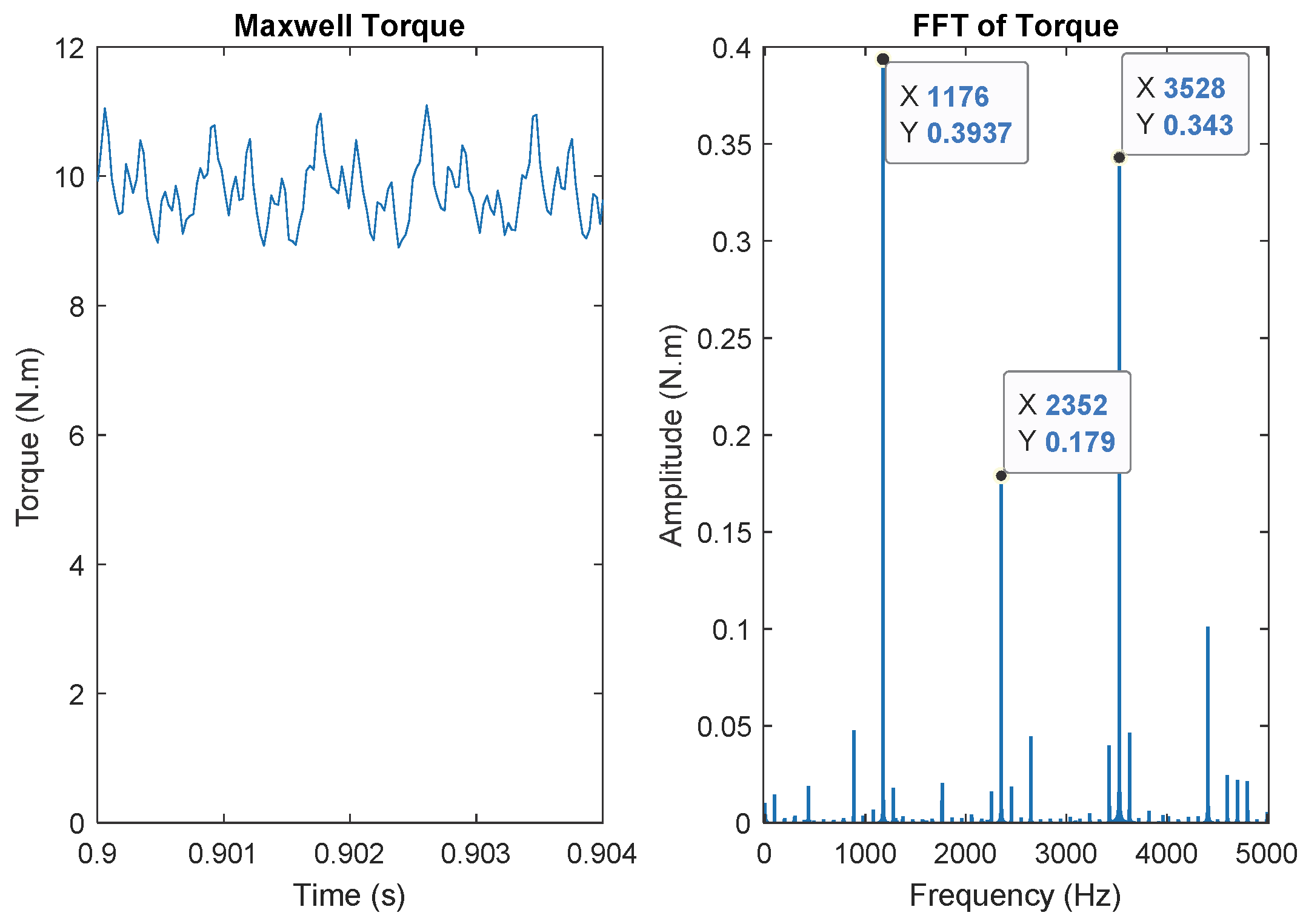
The simulated machine has a 36 stator slots, two investigated numbers of rotor bars 48 and 49, and two pole-pairs. The torque variation is extracted from the simulation results (for the machine with 48 bars), and a harmonic analysis is done and shown in Figure 3.
As we can see in 
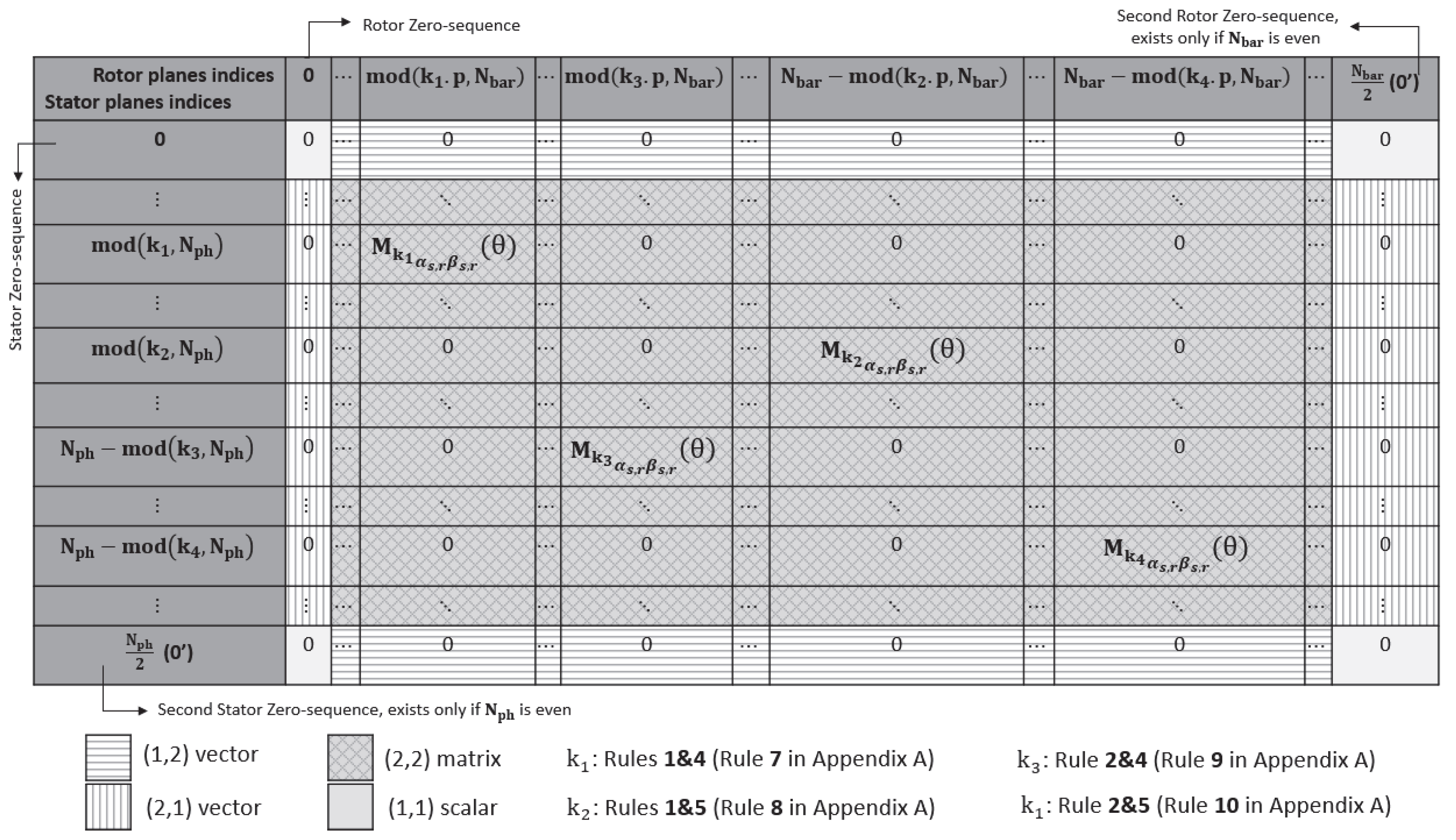
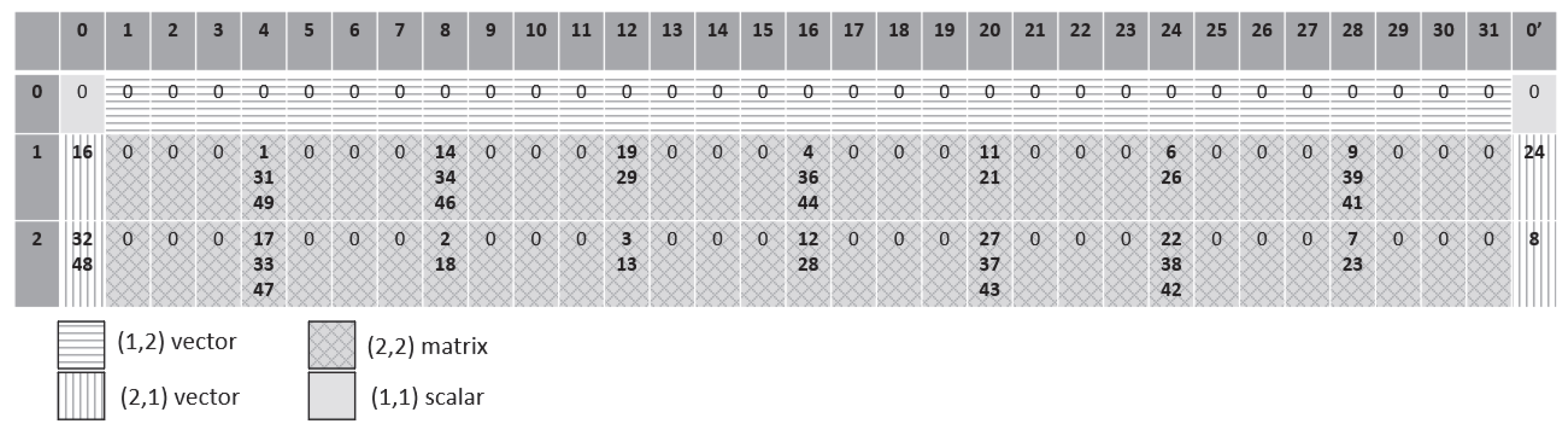
Figure 3, there are three predominant pulsating frequencies (1176 Hz, 2352 Hz and 3528 Hz). To understand the origin of these frequencies, it is important to determine the interactions between space and time harmonics. The distribution of space harmonics (up to v = 50) in the matrix L sr α β _ ( θ ) , according to Figure 2, is shown in 
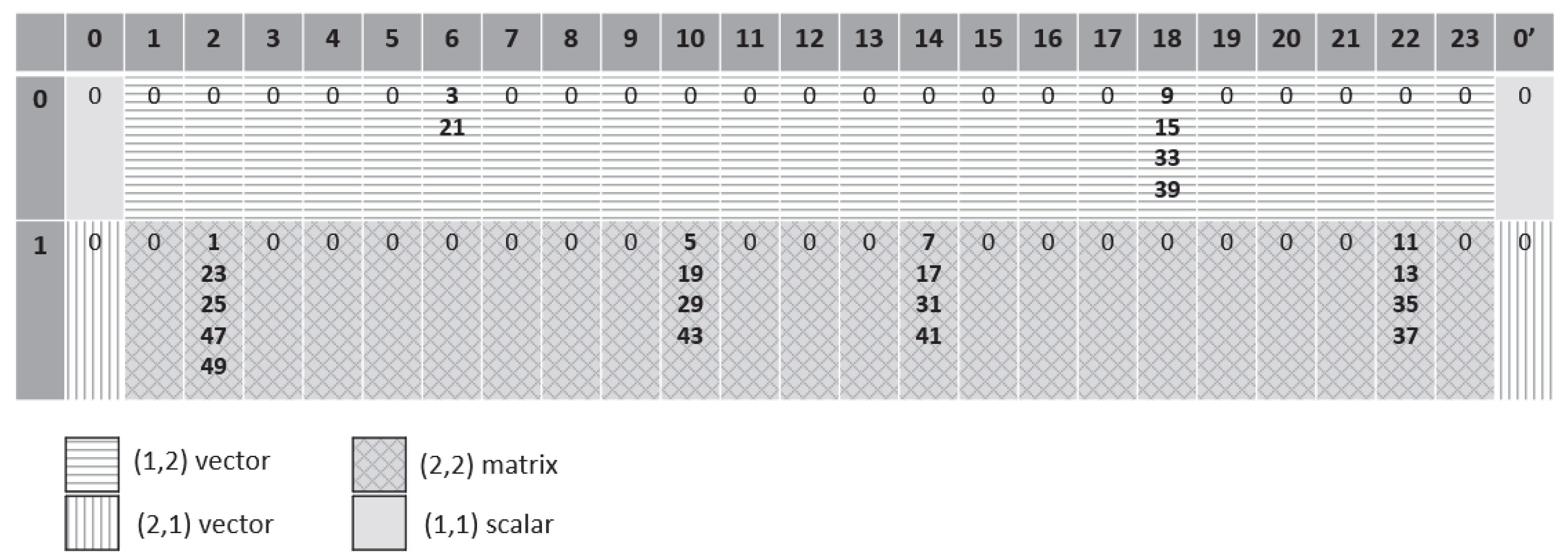
Figure 4. To simplify the presentation, each space harmonic “v.p” is represented by the number “v” in Figure (v = 1, …, 50).
All the even order harmonics are null, according to the winding distribution, so only odd order harmonics appear in the matrix.
The first line (0) in the table corresponds to the stator zero-sequence. For this zero-sequence, the harmonics 3 and 21 can excite the plane n°6 of the rotor and the harmonics 9, 15, 33 and 39 can excite the plane n°18 of the rotor. With a wye-connected three-phase machine, the zero-sequence is not excited. As consequence the plane n°6 and n°18 are not excited.
The second line (1) corresponds to the only possible stator plane in the case of this three-phase machine, which can be excited be sequences “u = 1” or “u = 2”. For this stator plane, four different rotor planes are excited (n°2, n°10, n°14, n°22), each one of them contains several superposed harmonics. As example the rotor plane n°2 is excited by the space harmonics n°1, 23, 25, 47 and 49.
In Figure 4, the number of bars is even, so a second rotor zero-sequence appears in column 0’.
According to the Equations (20), (27) and Table A1 in Appendix B, the frequencies of pulsating torque components can be predicted (shown in Table 4).
In this table, we find the same three predominant frequencies in Figure 3, which are 1176, 2352 and 3528 Hz. Each frequency results from many interactions between space and time harmonics. For example, the frequency 1176 Hz (the highest torque pulsation) results from the interactions: 1p-23p, 1p-25p, 25p-49p, 5p-19p, 5p-29p, 19p-43p, 7p-17p, 7p-31p, 17p-41p, 11p-13p, 11p-35p and 13p-37p.
According to the Table A3 in Appendix C, the 10 most important space harmonics (excited by the sequence “u = 1”) regarding their amplitudes in the winding function are: v = 1, 5, 7, 11, 13, 17, 19, 23, 35, 37. An interaction between two of these harmonics is considered important regarding the amplitude of torque pulsation. These significant interactions are colored in gray in the Table 4. We observe that most of these colored interactions generate a pulsation at 1176 Hz, which is consistent with F-E results (Figure 3), where the highest amplitude of torque ripple is at 1176 Hz.
Basing on Figure 3, this machine with 48 bars, presents many superpositions between space harmonics (in the same rotor planes). All these harmonics interactions can be avoided by taking 49 bars instead of 48. Figure 5 shows how the choice of 49 bars improves the separation between harmonics, all the harmonics below v = 50 are perfectly separated.
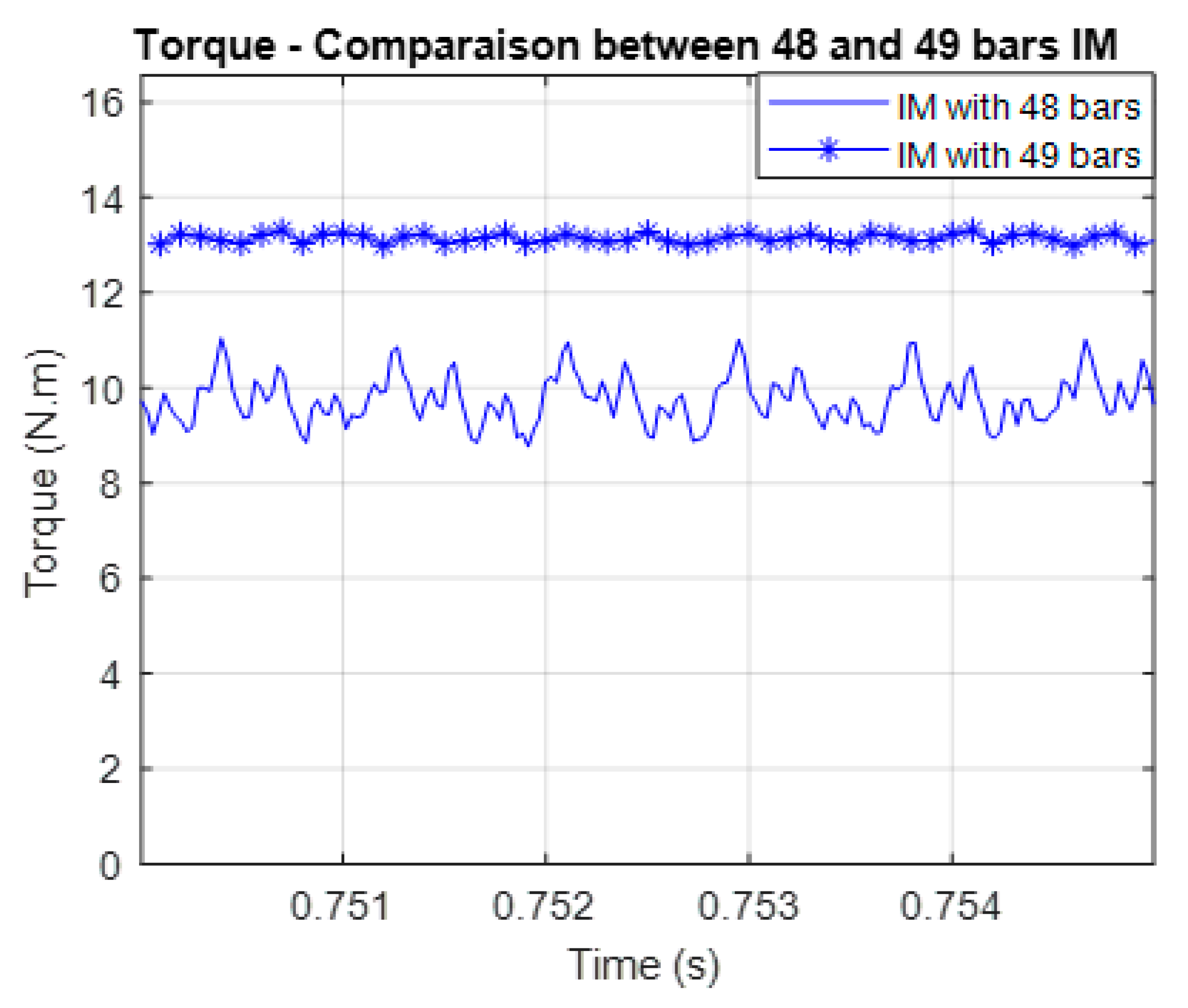
The Figure 6 shows the comparison between the three-phase IM with 48 and 49 bars regarding the torque (F-E results). It proves that the torque is smoother with 49 bars thanks to the good separation between space harmonics into several α-β rotor planes (as shown in Figure 5).
This result is consistent with the rules related to the choice of rotor bars number described in the reference [2] (pp. 340–341). According to this reference, for this machine topology (three phases, 36 stator slots and two pole-pairs), the number of bars 48 presents harmful parasitic torque, which is explained thanks to this new approach of prediction of torque pulsations.
After this first example, we conclude that even for three-phase induction machines, the classical approach of rotor cage modeling (simply by one α-β rotor plane) can only be used if the combination of phase number and bar number does not lead to harmful interactions between space and time harmonics (like the combination Nph = 3, Nbar = 49 and p1 = 2). However, when the combination causes harmful interactions (like the one with 48 bars in this example), it is important to consider several α-β rotor planes in modeling (4 planes in this example, for 48 bars) to predict the parasitic torque pulsations.

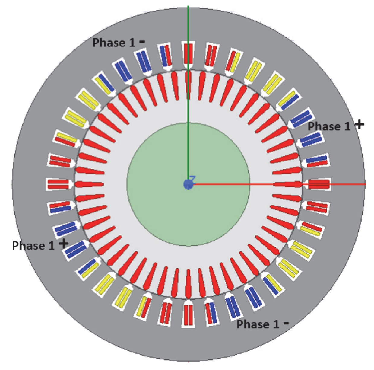
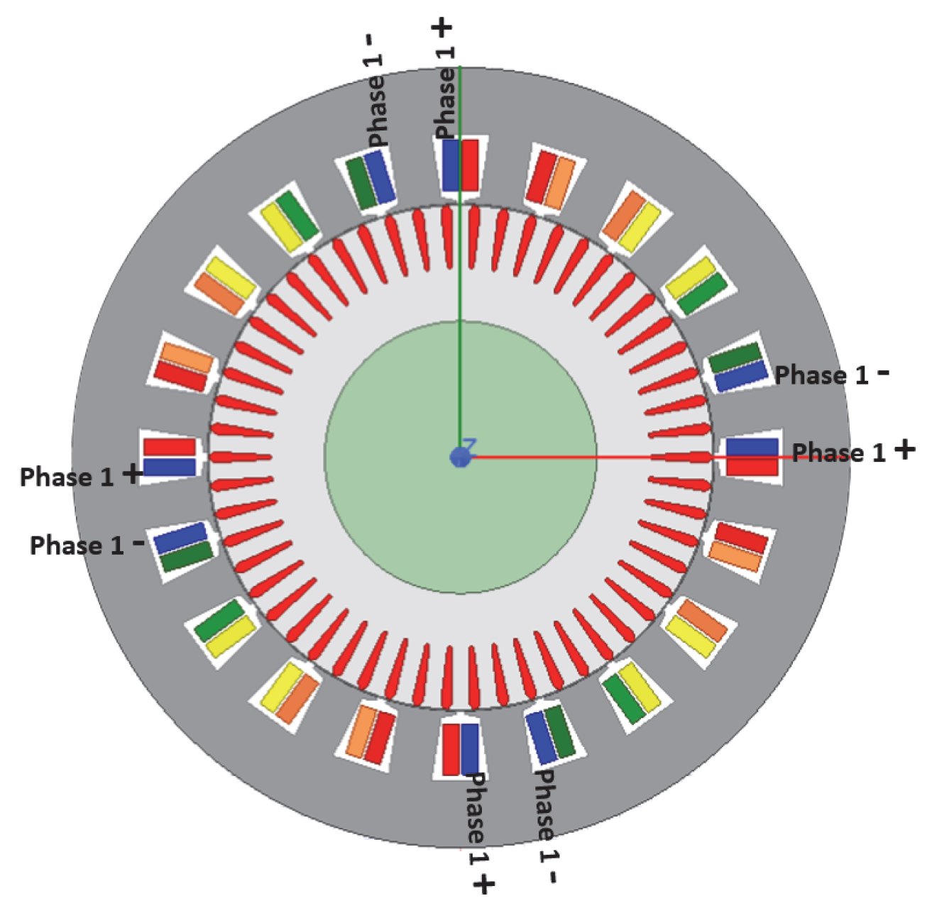
5.2. Five-Phase Induction Machine with Double-Layer Tooth Concentrated Winding

The machine parameters are shown in Appendix D. The Table 5 shows simulation parameters.
Two different stator sequences are imposed in separate simulations (u = 1 and u = 3). According to the Equation (19), the sequence “u = 1” induces in the rotor bars the set of harmonics “v = 1, −4, 6, −9, 11, −14, 16, −19 …”. The sequence “u = 3” induces the set of rotor current harmonics “v = −2, 3, −7, 8, −12, 13, −17, 18 …”.
This machine was studied in a previous paper [22]. In this paper it has been observed that the number of bars 64 presents important torque pulsations, especially referring to the number 65 characterized by a very low torque harmonics content. Nevertheless, according to the rules in the reference [2] (pp. 340–341), for this machine topology (5 phases, 20 stator slots and 4 pole-pairs) the number of bars 64 is not forbidden. In fact, the reported rules for selecting the rotor bars number are defined for three-phase machines and are not directly applicable to multiphase machines.
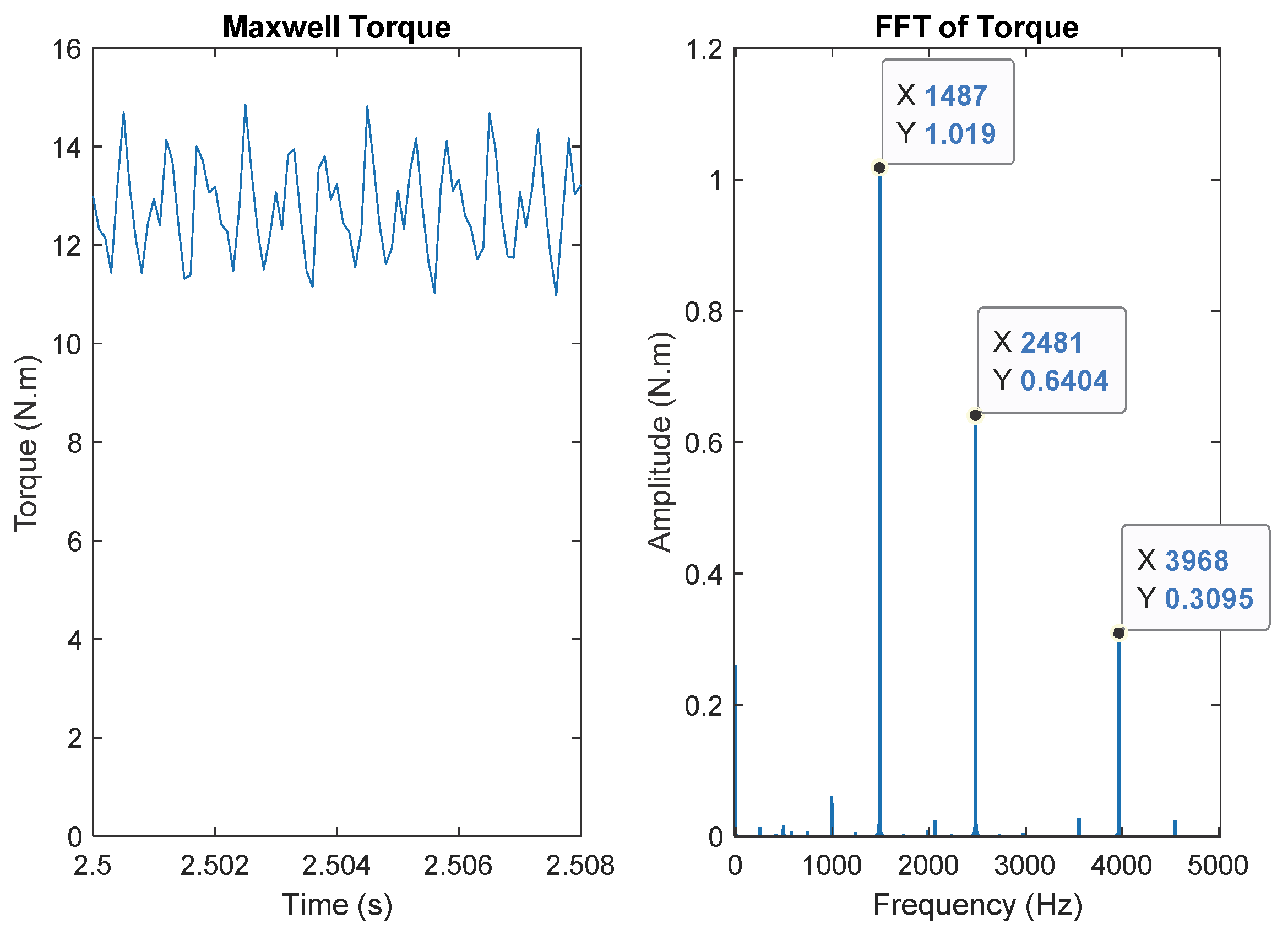
To explain the origin of torque pulsations for this machine with 64 bars, the developed torque under both sequences is extracted from the simulation results, and a harmonic analysis is done and shown in Figure 7 and Figure 8.
With this number of bars, the developed torque under both sequences contains important pulsating components. To understand the origin of these components, the distribution of space harmonics (up to v = 50) in the matrix L sr α β _ ( θ ) , according to the Figure 2, is shown in the Figure 9.
This figure shows the interactions between space and time harmonics.
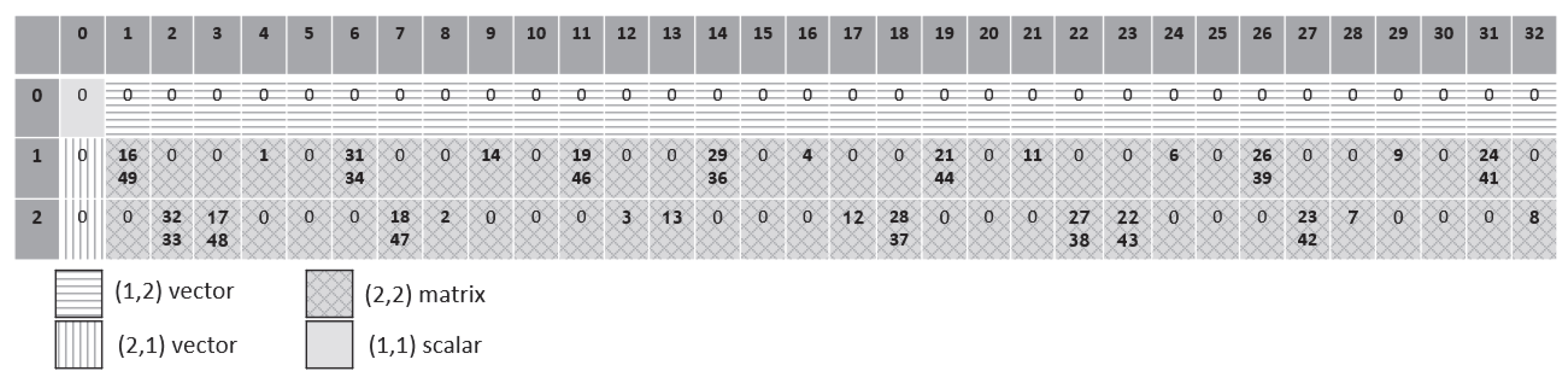
The space harmonics generated by the sequence “u = 1” are distributed in the second line of Figure, and the sequence “u = 3” corresponds to the third line. Under both stator sequences, seven rotor planes, the first rotor zero-sequence (column 0) and the second rotor zero-sequence (column 0’) are excited, each one of them contains several superposed harmonics.
According to the Appendix B, the frequencies of pulsating torque components can be predicted for the sequence “u = 1” in Table 6 and for the sequence “u = 3” in 
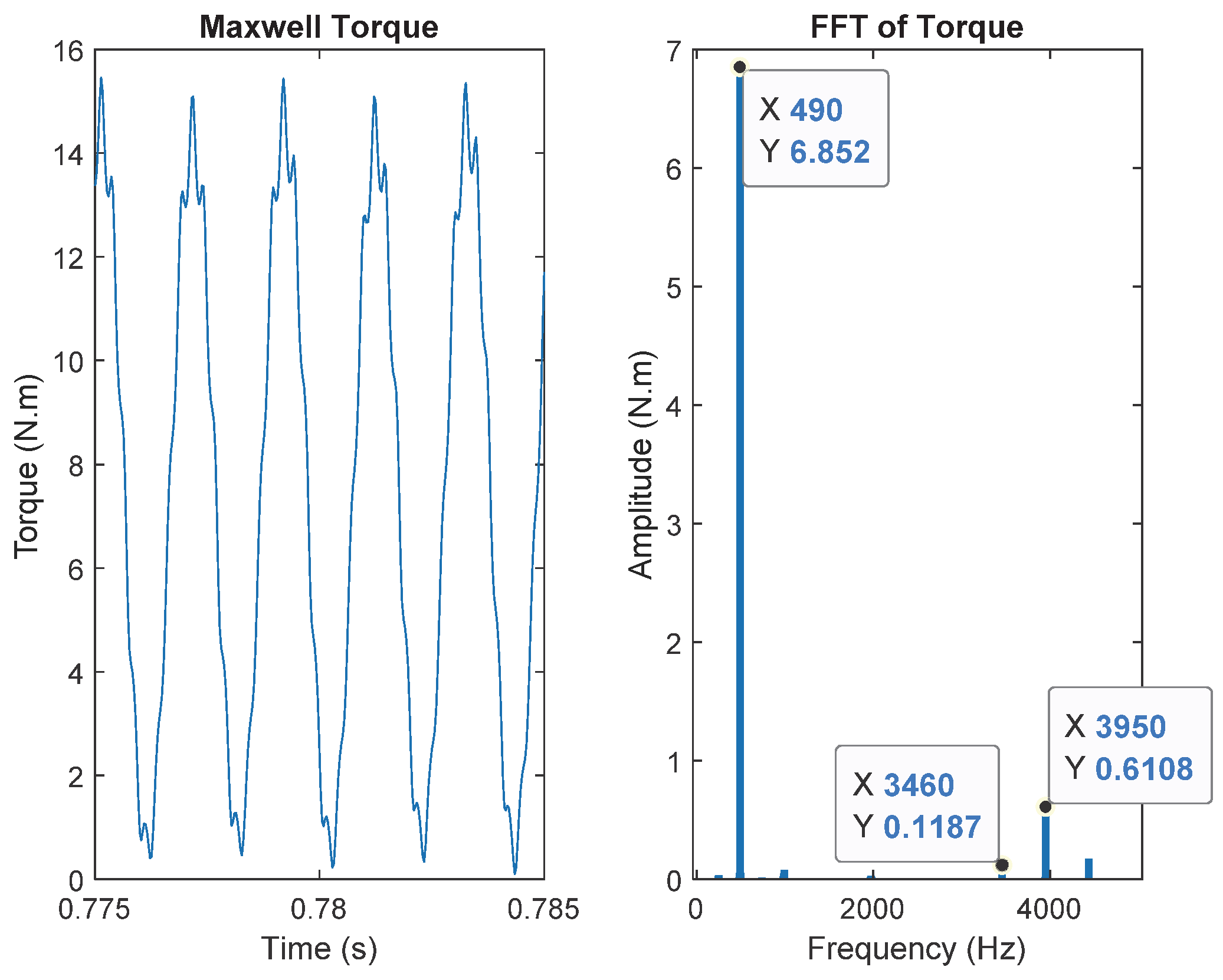
Table 7. According to the Table 6, the frequencies of torque pulsations for the sequence “u = 1” (space harmonics considered up to “v = 50”) are: 1487, 2481 and 3968 Hz. These frequencies are the same as the predominant frequencies in F-E results (Figure 7). The interactions in the Table 7 produce three main frequencies: 490, 3460 and 3950 Hz, the same as F-E results in Figure 8.
In Appendix D, the 20 most important space harmonics regarding amplitude are indicated in the Table A4. To have an idea about the importance of a torque pulsation, every interaction between two harmonics among the 20 most important ones (Table A4) is colored in gray.
Under the sequence “u = 1”, the only interaction between a space and a time harmonic whose amplitudes are among the 20 most important, is in the cell corresponding to the rotor zero-sequence containing the harmonic “16.p”, whose interaction generates two components (as explained in Appendix B): a constant torque at 0 Hz, and a pulsating component of a frequency of 1487 Hz (which has the highest pulsation amplitude in Figure 7).
Under the sequence “u = 3”, several interactions are colored in gray (interaction between two harmonics among the 20 most important in Table A4). All these marked interactions generate a frequency of 490 Hz, which has the highest pulsation amplitude in Figure 8.
The Figure 10 shows the space harmonics distribution in L sr α β _ ( θ ) for the machine with 65 bars. We observe that this number of bars allows to separate the harmonics better than the case of 64 bars. In fact, the harmonics with the most important amplitudes (Table A4) do not interact between each other. Furthermore, with this number of bars, the rotor zero-sequence is not excited under both sequences.
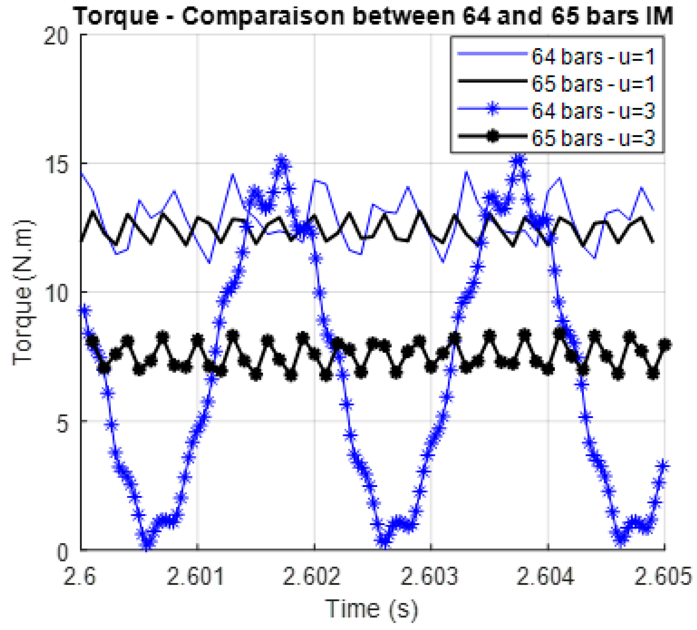
The Figure 11 shows the comparison of the developed torque between the machines with 64 and 65 bars. With 65 bars the torque is smoother under both sequences thanks to the separation of harmonics (shown in Figure 10). FFT analysis of torque for the new number of bars “65”, is done and shown in Figure 12 for both sequences.
Under the sequence “u = 1” (corresponds to the black curve in Figure 11), the predominant pulsating component is at the frequency of 3224 Hz. After the application of equations in Appendix B, it appears that this frequency of 3224 Hz is generated by all the interactions shown in Figure 10 (Line 1), so the interactions: 16p-49p, 31p-34p, 19p-49p, 29p-36p, 21p-44p, 26p-39p and 24p-41p (Considering only 50 space harmonics, from 1p to 50p). Comparing to the case of 64 bars (Table 6), the interactions in the machine with 65 bars are mostly between harmonics with relatively low amplitudes (Table A4) which explains the reduction of torque ripple thanks to this combination (Nph = 5, Nbar = 65 and p1 = 4).
Under the sequence “u = 3” (corresponds to the blue curve in Figure 11), the predominant pulsating component is at the frequency of 3211 Hz. Using the same approach (Appendix B), we determine that this frequency is generated by all the interactions in the last line of Figure 10, so: 32p-33p, 17p-48p, 18p-47p, 28p-37p, 27p-38p, 22p-43p, 23p-42p. These harmonics have also relatively low amplitudes (Table A4).
For five-phase induction machine, two α-β stator planes must be considered in modeling. The number of α-β rotor planes to be considered depends on the number of rotor bars. If there are interactions between harmonics with important amplitudes, the rotor planes containing these interactions must be considered to predict torque pulsations.

6. Conclusion

In order to be able to design multiphase induction drives which can be supplied with different harmonics of currents either for speed extension or for torque increase, the paper provides a mathematical approach to point out the excited α-β rotor planes which must be considered at two levels for the modelling. At first, during the electromagnetic design, the aim is to avoid wrong choices of bar numbers leading to torque pulsations. Secondly during the design of the vector control of the machine, it is necessary to use the simplest modeling of the rotor, with the minimum dimension, in order to define the vector control. The selection of the minimum number of rotor planes which contribute to the torque leads to a reduced-order modelling of the rotor cage. It has been shown that the rotor dimension, which is “Nbar” in the natural base model, can be much lower in the Concordia frame.
In this study, a general arithmetic tool (based on equations in Appendix B) was developed to predict, and consequently to avoid, torque ripples due to wrong combinations of phase number and rotor bar number. The result of the analysis is presented graphically in simple table where it is appearing clearly when interactions between space and time harmonics occur. This tool requires as inputs: the numbers of stator phases, rotor bars, pole-pairs (p1), the stator frequency, the stator sequence “u” and the mechanical speed. It should be mentioned that this tool does not predict the pulsations due to slotting effect.
This arithmetic tool is validated on two different multiphase induction machines topologies (three and five phases) with different numbers of rotor bars. In the provided applications, the induced pulsating torque frequencies are predicted thanks to the arithmetic tool and validated by the FFT analysis of the steady-state torque determined by F-E simulations (Maxwell 2D software, with imposed sinusoidal stator currents).
Through the first application, it has been concluded that even for three-phase induction machines the simplified modeling of the rotor cage by only one equivalent two-phase circuit is not always relevant. Some numbers of bars lead to important interactions between space and time harmonics, and consequently important torque pulsations. To predict these pulsations, it is important to consider all the excited rotor planes (and not only the one containing the fundamental space harmonic). With a difference of one bar quite significant differences are observed and explained.
For five-phase induction machines, it is possible to use two independent sequences to supply the stator. The proposed mathematical approach permitted to model the rotor under both sequences, to predict precisely torque pulsations frequencies for two different numbers of bars. These results allow to explain the important difference in torque ripple, between the five-phase machines with 64 and 65 rotor bars, observed in a previous paper [22].
To design a multiphase induction machine the combination of phase number and rotor bar number must be carefully chosen, considering the different possible polarities related to the used supply sequences. In the literature [1,2], the reported rules regarding this choice are defined for three-phase machines and are not directly applicable to multiphase induction machines. Thanks to the arithmetic tool and the corresponding graphical representation proposed in this paper, the wrong combinations can be predicted and avoided thanks to very fast calculations.
Further work is ongoing regarding the identification of mutual inductance coefficients “ M sr v ” to predict precisely the amplitudes of torque pulsations and the mean torque under different supplying sequences for multiphase induction machines and under different levels of magnetic saturation.

Author Contributions

A.M. proposed the used mathematical approach, worked on the numerical applications, analyzed the results, proposed the structure of the paper and wrote it. E.S. improved the structure of the paper and its content and provided advanced theoretical elements. F.S. improved the structure of the paper and its content and helped in the analysis of results. H.Z. improved the content of the paper. All authors validated the final paper. All authors have read and agreed to the published version of the manuscript.

Conflicts of Interest

The authors declare no conflict of interest.

Nomenclature

NphNumber of stator phases
NbarNumber of rotor bars
sppNumber of slots per pole and per phase
pNumber of pole-pairs
V _ s Stator voltage vector, dimension Nph
I _ s Stator current vector, dimension Nph
I _ r Rotor current vector, dimension Nbar
ϕ _ s Stator flux vector, dimension Nph
ϕ _ r Rotor flux vector, dimension Nbar
R s _ Stator resistance matrix, dimension Nph × Nph (Diagonal matrix)
R r _ Rotor resistance matrix, dimension Nbar × Nbar
L ss _ Stator inductance matrix, dimension Nph × Nph
L rr _ Rotor inductance matrix, dimension Nbar × Nbar
L sr _ = L rs _ Mutual inductance matrix (between stator and rotor), dimension Nph × Nbar
θ Mechanical angle
R s Stator phase resistance
R b Rotor bar resistance
R e Resistance of end-connection ring portion (connecting 2 adjacent bars)
L sij Mutual inductance between two stator phases “i” and “j”
L ls Leakage stator inductance
L rij Mutual inductance between two rotor phases “i” and “j”
L b Rotor bar leakage inductance
L e Leakage inductance of end-connection ring portion
I s u Stator current amplitude (for the stator sequence “u”)
f s u Stator current frequency (for the stator sequence “u”)
φ s u Stator current phase (for the stator sequence “u”)
I r v Amplitude of induced rotor current harmonic “v”
f r v Frequency of the induced rotor current harmonic “v”
φ r v Phase of the induced rotor current harmonic “v”
Ω mec Mechanical speed

Appendix A

As seen in Figure 2, each space harmonic “k” is projected on a cell represented by M k α s , r β s , r _ ( θ ) (Equation (18)), which can be a two-by-two matrix, a two-element vector or a scalar, depending on the rules described below:
  • Rule 7: If mod ( k , N ph ) floor ( N ph 2 ) and mod ( k . p , N bar ) floor ( N bar 2 ) :
    M k α s , r β s , r _ ( θ ) = N ph . N bar 2 . M sr k ( cos ( kp θ + φ sr k ) sin ( kp θ + φ sr k ) sin ( kp θ + φ sr k ) cos ( kp θ + φ sr k ) )
  • Rule 8: If mod ( k , N ph ) floor ( N ph 2 ) and mod ( k . p , N bar ) > floor ( N bar 2 ) :
    M k α s , r β s , r _ ( θ ) = N ph . N bar 2 . M sr k ( cos ( kp θ + φ sr k ) sin ( kp θ + φ sr k ) sin ( kp θ + φ sr k ) cos ( kp θ + φ sr k ) )
  • Rule 9: If mod ( k , N ph ) > floor ( N ph 2 ) and mod ( k . p , N bar ) floor ( N bar 2 ) :
    M k α s , r β s , r _ ( θ ) = N ph . N bar 2 . M sr k ( cos ( kp θ + φ sr k ) sin ( kp θ + φ sr k ) sin ( kp θ + φ sr k ) cos ( kp θ + φ sr k ) )
  • Rule 10: If mod ( k , N ph ) > floor ( N ph 2 ) and mod ( k . p , N bar ) > floor ( N bar 2 ) :
    M k α s , r β s , r _ ( θ ) = N ph . N bar 2 . M sr k ( cos ( kp θ + φ sr k ) sin ( kp θ + φ sr k ) sin ( kp θ + φ sr k ) cos ( kp θ + φ sr k ) )
  • Rule 11: If mod ( k , N ph ) = 0 and mod ( k . p , N bar ) floor ( N bar 2 ) :
    M k α s , r β s , r _ ( θ ) = N ph . N bar 2 . M sr k ( cos ( kp θ + φ sr k ) sin ( kp θ + φ sr k ) )
  • Rule 12: If mod ( k , N ph ) = 0 and mod ( k . p , N bar ) > floor ( N bar 2 ) :
    M k α s , r β s , r _ ( θ ) = N ph . N bar 2 . M sr k ( cos ( kp θ + φ sr k ) sin ( kp θ + φ sr k ) )
  • Rule 13 (Only when N ph is even): If mod ( k , N ph ) = N ph 2 and mod ( k . p , N bar ) floor ( N bar 2 ) :
    M k α s , r β s , r _ ( θ ) = N ph . N bar 2 . M sr k ( cos ( kp θ + φ sr k ) sin ( kp θ + φ sr k ) )
  • Rule 14 (Only when N ph is even): If mod ( k , N ph ) = N ph 2 and mod ( k . p , N bar ) > floor ( N bar 2 ) :
    M k α s , r β s , r _ ( θ ) = N ph . N bar 2 . M sr v ( cos ( kp θ + φ sr k ) sin ( kp θ + φ sr k ) )
  • Rule 15: If mod ( k , N ph ) floor ( N ph 2 ) and mod ( k . p , N bar ) = 0 :
    M k α s , r β s , r _ ( θ ) = N ph . N bar 2 . M sr k ( cos ( kp θ + φ sr k ) sin ( kp θ + φ sr k ) )
  • Rule 16: If mod ( k , N ph ) > floor ( N ph 2 ) and mod ( k . p , N bar ) = 0 :
    M k α s , r β s , r _ ( θ ) = N ph . N bar 2 . M sr k ( cos ( kp θ + φ sr k ) sin ( kp θ + φ sr k ) )
  • Rule 17 (Only when N bar is even): If mod ( k , N ph ) floor ( N ph 2 ) and mod ( k . p , N bar ) = N bar 2 :
    M k α s , r β s , r _ ( θ ) = N ph . N bar 2 . M sr k ( cos ( kp θ + φ sr k ) sin ( kp θ + φ sr k ) )
  • Rule 18 (Only when N bar is even): If mod ( k , N ph ) > floor ( N ph 2 ) and mod ( k . p , N bar ) = N bar 2 :
    M k α s , r β s , r _ ( θ ) = N ph . N bar 2 . M sr k ( cos ( kp θ + φ sr k ) sin ( kp θ + φ sr k ) )
  • Rule 19: If mod ( k , N ph ) = 0 and mod ( k . p , N bar ) = 0 :
    M k α s , r β s , r _ ( θ ) = N ph . N bar . M sr k ( cos ( kp θ + φ sr k ) )
  • Rule 20 (Only when N bar is even): If mod ( k , N ph ) = 0 and mod ( k . p , N bar ) = N bar 2 :
    M k α s , r β s , r _ ( θ ) = N ph . N bar . M sr k ( cos ( kp θ + φ sr k ) )
  • Rule 21 (Only when N ph is even): If mod ( k , N ph ) = N ph 2 and mod ( k . p , N bar ) = 0 :
    M k α s , r β s , r _ ( θ ) = N ph . N bar . M sr k ( cos ( kp θ + φ sr k ) )
  • Rule 22 (Only when N ph and N bar are even): If mod ( k , N ph ) = N ph 2 and mod ( k . p , N bar ) = N bar 2 :
    M k α s , r β s , r _ ( θ ) = N ph . N bar . M sr k ( cos ( kp θ + φ sr k ) )
In the case where two, or more, harmonics are projected on the same stator and rotor planes, the matrices M α β k _ related to these harmonics are superposed.

Appendix B

Under a stator sequence “u”, the pulsating torque component due to the interaction between a space harmonic “v1.p” and a rotor time harmonic “v2.p” can be expressed, in the general form, as follows:
T v 1 v 2 = N ph . N bar 4 . p . | v 1 | . I s u . I r v 2 . ( M sr ) v 1 . sin ( δ s ( ω s u . t + φ s u ) + δ r ( | ω r v 2 | . t + φ r v 2 ) + δ sr ( | v 1 | . p . mec . t + φ sr v 1 ) )
where: δ s ,   δ r   and   δ sr = ± 1 . These coefficients depend on the rules (Appendix A) related to the harmonics “v1.p” and “v2.p”. The different cases of the coefficients δ s ,   δ r   and   δ sr are shown in the Table A1 (Only rules 7 to 10 are considered).
Table A1. Pulsating torque components due to interactions of harmonics of rules 7, 8, 9 and 10.
m o d ( u , N p h ) < f l o o r ( N p h 2 ) m o d ( u , N p h ) > f l o o r ( N p h 2 )
Rule of “v2.p”Rule 7Rule 8Rule 9Rule 10Rule 7Rule 8Rule 9Rule 10
Rule of “v1.p”
Rule 7 δ s = 1
δ r = 1
δ sr = 1
δ s = 1
δ r = 1
δ sr = 1
δ s = 1
δ r = 1
δ sr = 1
δ s = 1
δ r = 1
δ sr = 1
δ s = 1
δ r = 1
δ sr = 1
δ s = 1
δ r = 1
δ sr = 1
δ s = 1
δ r = 1
δ sr = 1
δ s = 1
δ r = 1
δ sr = 1
Rule 8 δ s = 1
δ r = 1
δ sr = 1
δ s = 1
δ r = 1
δ sr = 1
δ s = 1
δ r = 1
δ sr = 1
δ s = 1
δ r = 1
δ sr = 1
δ s = 1
δ r = 1
δ sr = 1
δ s = 1
δ r = 1
δ sr = 1
δ s = 1
δ r = 1
δ sr = 1
δ s = 1
δ r = 1
δ sr = 1
Rule 9 δ s = 1
δ r = 1
δ sr = 1
δ s = 1
δ r = 1
δ sr = 1
δ s = 1
δ r = 1
δ sr = 1
δ s = 1
δ r = 1
δ sr = 1
δ s = 1
δ r = 1
δ sr = 1
δ s = 1
δ r = 1
δ sr = 1
δ s = 1
δ r = 1
δ sr = 1
δ s = 1
δ r = 1
δ sr = 1
Rule 10 δ s = 1
δ r = 1
δ sr = 1
δ s = 1
δ r = 1
δ sr = 1
δ s = 1
δ r = 1
δ sr = 1
δ s = 1
δ r = 1
δ sr = 1
δ s = 1
δ r = 1
δ sr = 1
δ s = 1
δ r = 1
δ sr = 1
δ s = 1
δ r = 1
δ sr = 1
δ s = 1
δ r = 1
δ sr = 1
When a rotor zero-sequence is excited (rules 15, 16, 17 and 18 in Appendix A), the general form of the developed torque component due to the interaction of “v3.p” and “v4.p” (both exciting rotor zero-sequences) can be written as follows:
T v 3 v 4 = N ph . N bar 4 . p . | v 3 | . I s u . I r v 4 . ( M sr ) v 3 . sin ( δ s 1 ( ω s u . t + φ s u ) + δ r 1 ( | ω r v 4 | . t + φ r v 4 ) + δ sr 1 ( | v 3 | . p . m e c . t + φ s r v 3 ) ) + sin ( δ s 2 ( ω s u . t + φ s u ) + δ r 2 ( | ω r v 4 | . t + φ r v 4 ) + δ sr 2 ( | v 3 | . p . m e c . t + φ s r v 3 ) )
The different cases of the coefficients δ s 1 ,   δ s 2 ,   δ r 1 ,   δ r 2   and   δ sr 1 ,     δ sr 2 are shown in the Table A2.
Table A2. Pulsating torque components due to interactions of harmonics of rules 15, 16, 17 and 18.
m o d ( u , N p h ) < f l o o r ( N p h 2 ) m o d ( u , N p h ) > f l o o r ( N p h 2 )
Rule of “v4.p”Rule 15Rule 16Rule 17Rule 18Rule 15Rule 16Rule 17Rule 18
Rule of “v3.p”
Rule 15 δ s 1 = 1
δ r 1 = 1
δ sr 1 = 1
δ s 2 = 1
δ r 2 = 1
δ sr 2 = 1
δ s 1 = 1
δ r 1 = 1
δ sr 1 = 1
δ s 2 = 1
δ r 2 = 1
δ sr 2 = 1
δ s 1 = 1
δ r 1 = 1
δ sr 1 = 1
δ s 2 = 1
δ r 2 = 1
δ sr 2 = 1
δ s 1 = 1
δ r 1 = 1
δ sr 1 = 1
δ s 2 = 1
δ r 2 = 1
δ sr 2 = 1
Rule 16 δ s 1 = 1
δ r 1 = 1
δ sr 1 = 1
δ s 2 = 1
δ r 2 = 1
δ sr 2 = 1
δ s 1 = 1
δ r 1 = 1
δ sr 1 = 1
δ s 2 = 1
δ r 2 = 1
δ sr 2 = 1
δ s 1 = 1
δ r 1 = 1
δ sr 1 = 1
δ s 2 = 1
δ r 2 = 1
δ sr 2 = 1
δ s 1 = 1
δ r 1 = 1
δ sr 1 = 1
δ s 2 = 1
δ r 2 = 1
δ sr 2 = 1
Rule 17 δ s 1 = 1
δ r 1 = 1
δ sr 1 = 1
δ s 2 = 1
δ r 2 = 1
δ sr 2 = 1
δ s 1 = 1
δ r 1 = 1
δ sr 1 = 1
δ s 2 = 1
δ r 2 = 1
δ sr 2 = 1
δ s 1 = 1
δ r 1 = 1
δ sr 1 = 1
δ s 2 = 1
δ r 2 = 1
δ sr 2 = 1
δ s 1 = 1
δ r 1 = 1
δ sr 1 = 1
δ s 2 = 1
δ r 2 = 1
δ sr 2 = 1
Rule 18 δ s 1 = 1
δ r 1 = 1
δ sr 1 = 1
δ s 2 = 1
δ r 2 = 1
δ sr 2 = 1
δ s 1 = 1
δ r 1 = 1
δ sr 1 = 1
δ s 2 = 1
δ r 2 = 1
δ sr 2 = 1
δ s 1 = 1
δ r 1 = 1
δ sr 1 = 1
δ s 2 = 1
δ r 2 = 1
δ sr 2 = 1
δ s 1 = 1
δ r 1 = 1
δ sr 1 = 1
δ s 2 = 1
δ r 2 = 1
δ sr 2 = 1
For the rotor zero-sequence harmonics, the interaction between a space harmonic “v.p” and the time harmonic (of rotor current) of the same range “v.p” generates a constant torque and a pulsating component in the same time.

Appendix C

The three-phase induction machine has an overlapping distributed winding, its geometry is shown in Figure A1.
Figure A1. Geometry of the three-phase induction machine.
Mca 25 00011 g0a1
The parameters of this machine are:
  • Number of phases, Nph = 3;
  • Number of stator slots, Ns = 36;
  • Number of rotor bars (2 compared cases), Nbar = 48, 49;
  • Number of pole-pairs under first current harmonic injection, p1 = 2;
  • Rated stator current, Is = 325 Apeak;
  • Rated torque, T = 72 N.m.
The Table A3 shows the harmonic winding factors for the 50 first space harmonics. The winding factor “kv” divided by its range “v” reflects the importance of the harmonic in torque production. In fact, the coefficient M sr v is proportional to the factor “kv/v” (in the column 3). The lines containing the 15 most important space harmonics are colored in gray in the table.
Table A3. Harmonic winding factors of the three-phase winding.
vkvkv/vvkvkv/vvkvkv/vvkvkv/vvkvkv/v
10.9450.945110.0610.006210.5770.027310.1400.005410.1400.003
2001200220032004200
30.5770.192130.1400.011230.1400.006330.5770.017430.0610.001
4001400240034004400
50.1400.028150.5770.038250.0610.002350.9450.0274500
6001600260036004600
70.0610.009170.9450.0562700370.9450.026470.0610.001
8001800280038004800
900190.9450.050290.0610.002390.5770.015490.1400.003
10002000300040005000

Appendix D

The five-phase induction machine has a tooth-concentrated winding, its geometry is shown in Figure A2.
Figure A2. Geometry of the five-phase induction machine with double-layer tooth concentrated winding.
Mca 25 00011 g0a2
The parameters of this machine are:
  • Number of phases, Nph = 5;
  • Number of stator slots, Ns = 20;
  • Number of rotor bars (2 compared cases), Nbar = 64, 65;
  • Number of pole-pairs under first current harmonic injection, p1 = 4;
  • Rated stator current, Is = 400 Apeak;
  • Rated torque, T = 250 N.m.
The Table A4 shows the harmonic winding factors for the 50 first space harmonics. The winding factor “kv” divided by its range “v” reflect the importance of the harmonic in torque production. In fact, the coefficient M sr v is proportional to the factor “kv/v” (in the column 3). The lines containing the 20 most important space harmonics are colored in gray in the table.
Table A4. Harmonic winding factors of the five-phase winding.
vkvkv/vvkvkv/vvkvkv/vvkvkv/vvkvkv/v
10.590.59110.590.05210.590.03310.590.02410.590.01
20.950.48120.950.08220.950.04320.950.03420.950.02
30.950.32130.950.07230.950.04330.950.03430.950.02
40.590.15140.590.04240.590.02340.590.02440.590.01
5001500250035004500
60.590.10160.590.04260.590.02360.590.02460.590.01
70.950.14170.950.06270.950.04370.950.03470.950.02
80.950.12180.950.05280.950.03380.950.03480.950.02
90.590.07190.590.03290.590.02390.590.02490.590.01
10002000300040005000

References

  1. Boldea, I.; Nasar, S.A. The Induction Machine Handbook; CRC Press: Boca Raton, FL, USA, 2002. [Google Scholar]
  2. Pyrhönen, J.; Jokinen, T.; Hrabovcovà, V. Design of Rotating Electrical Machines; Wiley: Hoboken, NJ, USA, 2008. [Google Scholar]
  3. Lipo, T.A. Introduction to AC Machine Design; Wiley: Hoboken, NJ, USA, 2017. [Google Scholar]
  4. Kim, Y.; Koo, B.K.; Nam, K. Induction Motor Design Strategy for Wide Constant Power Speed Range. IEEE Trans. Ind. Electron. 2018, 66, 8372–8381. [Google Scholar] [CrossRef]
  5. Guan, Y.; Zhu, Z.; Afinowi, I.; Mipo, J. Influence of machine design parameters on flux- weakening performance of induction machine for electrical vehicle application. IET Electr. Syst. Transp. 2015, 5, 43–52. [Google Scholar] [CrossRef]
  6. Abdel-Khalik, A.S.; Gadoue, S.M.; Masoud, M.I.; Wiliams, B.W. Optimum flux distribution with harmonic injection for a multiphase induction machine using genetic algorithms. IEEE Trans. Energy Convers. 2011, 26, 501–512. [Google Scholar] [CrossRef]
  7. Mengoni, M.; Zarri, L.; Tani, A.; Parsa, L.; Serra, G.; Casadei, D. High-torque-density control of multiphase induction motor drives operating over a wide speed range. IEEE Trans. Ind. Electron. 2015, 62, 814–825. [Google Scholar] [CrossRef]
  8. Pereira, L.A.; Haffner, S.; Pereira, L.F.A.; da Rosa, R.S. Torque capability of high phase induction machines with sinusoidal and trapezoidal airgap field under steady state. In Proceedings of the 39th Annual Conference of the IEEE Industrial Electronics Society, Vienna, Austria, 10–13 November 2013; pp. 3183–3188. [Google Scholar]
  9. Kong, W.; Huang, J.; Qu, R.; Kang, M.; Yang, J. Nonsinusoidal Power Supply Analysis for Concentrated-Full-Pitch-Winding Multiphase Induction Motor. IEEE Trans. Ind. Electron. 2016, 63, 574–582. [Google Scholar] [CrossRef]
  10. Dajaku, G.; Bachheibl, F.; Patzak, A.; Gerling, D. Intelligent Stator Cage Winding for Automotive Traction Electric Machines. In Proceedings of the EVS28 International Electric Vehicle Symposium and Exhibition, Goyang, Korea, 3–6 May 2015; pp. 1–8. [Google Scholar]
  11. Yang, J.; Hu, H.; Huang, J. Electronic pole changing technique of multiphase induction motor based on vector control. Int. Trans. Electr. Energy Syst. 2012, 23, 901–913. [Google Scholar]
  12. Ge, B.; Sun, D.; Wu, W.; Peng, F.Z. Winding Design, Modeling, and Control for Pole-Phase Modulation Induction Motors. IEEE Trans. Magn. 2013, 49, 898–911. [Google Scholar] [CrossRef]
  13. Gautam, A.; Ojo, J.O. Variable Speed Multiphase Induction Machine Using Pole Phase Modulation Principle. In Proceedings of the 38th Annual Conference on IEEE Industrial Electronics Society, Montreal, QC, Canada, 25–28 October 2012; pp. 3659–3665. [Google Scholar]
  14. Magill, M.P.; Member, S.; Krein, P.T. A Dynamic Pole-Phase Modulation Induction Machine Model. In Proceedings of the 2015 IEEE International Electric Machines & Drives Conference (IEMDC), Coeur d’Alene, ID, USA, 10–13 May 2015; pp. 13–19. [Google Scholar]
  15. Grigore-Müler, O.; Barbelian, M. The simulation of a multi-phase induction motor drive. In Proceedings of the 12th International Conference on Optimization of Electrical and Electronic Equipment, Basov, Romania, 20–22 May 2010; pp. 297–306. [Google Scholar]
  16. Liu, Z.; Wu, J.; Hao, L. Coordinated and fault-tolerant control of tandem 1five-phase induction motors in ship propulsion system. IET Electr. Power Appl. 2017, 12, 91–97. [Google Scholar] [CrossRef]
  17. Patzak, A.; Bachheibl, F.; Baumgardt, A.; Dajaku, G.; Moros, O.; Gerling, D. Driving range evaluation of a multi-phase drive for low voltage high power electric vehicles. In Proceedings of the 2015 International Conference on Sustainable Mobility Applications, Renewables and Technology (SMART), Kuwait City, Kuwait, 23–25 November 2015; pp. 297–306. [Google Scholar]
  18. Kron, G. Rules to Predetermine Crawling, Vibration, Noise and Hooks in the Speed-Torque Curve Induction Motor Slot Combinations. Trans. Am. Inst. Electr. Eng. 1931, 50, 757–767. [Google Scholar] [CrossRef]
  19. Huang, J.; Kang, M.; Yang, J.; Jiang, H.; Liu, D. Multiphase Machine Theory and Its Applications. In Proceedings of the 2008 International Conference on Electrical Machines and Systems, Wuhan, China, 17–20 October 2008; pp. 1–7. [Google Scholar]
  20. Duran, M.J.; Salas, F.; Arahal, M.R. Bifurcation Analysis of Five-Phase Induction Motor Drives With Third Harmonic Injection. IEEE Trans. Ind. Electron. 2008, 55, 2006–2014. [Google Scholar] [CrossRef]
  21. Abdel-Khalik, A.S.; Masoud, M.I.; Ahmed, S.; Massoud, A.M. Effect of current harmonic injection on constant rotor volume multiphase induction machine stators: A comparative study. IEEE Trans. Ind. Appl. 2012, 48, 2002–2013. [Google Scholar] [CrossRef]
  22. Mekahlia, A.; Semail, E.; Scuiller, F.; Hamiti, T.; Benlamine, R. Effect of Rotor Bar Number on Performance of Five-Phase Induction Machine for Traction. In Proceedings of the 2018 XIII International Conference on Electrical Machines (ICEM), Alexandroupoli, Greece, 3–6 September 2018; pp. 185–190. [Google Scholar]
  23. Marfoli, A.; Sala, G.; Papini, L.; Bolognesi, P.; Gerada, C. Torque Ripple Investigation in Squirrel Cage Induction Machines. In Proceedings of the 2019 IEEE International Electric Machines & Drives Conference (IEMDC), San Diego, CA, USA, 12–15 May 2019; pp. 140–146. [Google Scholar]
  24. White, D.C.; Woodson, H.H. Electromechanical Energy Conversion; Wiley: Hoboken, NJ, USA, 1959. [Google Scholar]
  25. Gautam, A.; Ojo, O.; Ramezani, M.; Momoh, O. Computation of equivalent circuit parameters of nine-phase induction motor in different operating modes. In Proceedings of the IEEE Energy Conversion Congress and Exposition (ECCE), Raleigh, NC, USA, 15–20 September 2012; pp. 142–149. [Google Scholar]
  26. Magill, M.P.; Member, S.; Krein, P.T.; Haran, K.S.; Selection, A.P.W. Equivalent Circuit Model for Pole-Phase Modulation Induction Machines. In Proceedings of the 2015 IEEE International Electric Machines & Drives Conference (IEMDC), Coeur d’Alene, ID, USA, 10–13 May 2015; pp. 293–299. [Google Scholar]
  27. Fudeh, H.R.; Ong, C.M. Modeling and analysis of induction machines containing space harmonics: Part I: Modeling and Transformation. IEEE Trans. Power Appar. Syst. 1983, PAS-102, 2608–2615. [Google Scholar] [CrossRef]
  28. Toliyat, H.A.; Lipo, T.A.; White, J.C. Analysis of a Concentrated Winding Induction Machine for Adjustable Speed Drive Applications, Part I: Motor Analysis. IEEE Trans. Energy Convers. 1991, 6, 679–683. [Google Scholar] [CrossRef]
  29. Muñoz, A.R. Analysis and Control of a Dual Stator Winding Squirrel Cage Induction Machine Drive. Ph.D. Thesis, University of Wisconsin, Madison, WI, USA, 1999. [Google Scholar]
  30. Scuiller, F. Predicting the space harmonics generated by symmetrical multi-phase windings. In Proceedings of the 2019 IEEE International Electric Machines & Drives Conference (IEMDC), San Diego, CA, USA, 12–15 May 2019; pp. 1348–1355. [Google Scholar]
Figure 1. Squirrel cage rotor representation, figure taken from [29] (p. 60).
Mca 25 00011 g001
Figure 2. Transformed Stator–Rotor mutual inductance matrix L sr α β _ ( θ ) .
Mca 25 00011 g002
Figure 3. FFT of Finite-Element torque for the three-phase IM with 48 bars.
Mca 25 00011 g003
Figure 4. Space harmonics distribution in L sr α β _ ( θ ) for the three-phase IM with 48 bars (in line 1, 4 planes among 23 are excited, each one by several harmonics which lead to important interactions).
Mca 25 00011 g004
Figure 5. Space harmonics distribution in L sr α β _ ( θ ) for the three-phase IM with 49 bars (in line 1, 17 planes among 24 are excited, each one by one harmonic, so without interactions).
Mca 25 00011 g005
Figure 6. Comparison of the developed torque with 48 and 49 bars, three-phase IM.
Mca 25 00011 g006
Figure 7. FFT of Finite-Element torque for the five-phase IM with 64 bars. Under sequence “u = 1” (the planes of line (1), Figure 9 are excited).
Mca 25 00011 g007
Figure 8. FFT of Finite-Element torque for the five-phase IM with 64 bars. Under sequence “u = 3” (the planes of line (2), Figure 9 are excited).
Mca 25 00011 g008
Figure 9. Space harmonics distribution in L sr α β _ ( θ ) for the five-phase IM with 64 bars (in each line, 7 rotor planes, among 31, and both zero-sequences are excited, which lead to harmful interactions).
Mca 25 00011 g009
Figure 10. Space harmonics distribution in L sr α β _ ( θ ) for the five-phase IM with 65 bars (in line 1, 13 planes among 32 are excited. In line 2, 12 planes among 32 are excited. No zero-sequence is excited. This leads to less interactions than 64 bars).
Mca 25 00011 g010
Figure 11. Comparison of the developed torque with 64 and 65 bars, five-phase IM.
Mca 25 00011 g011
Figure 12. FFT analysis of torque curves for the IM with 65 bars, under sequences “u = 1” and “u = 3”.
Mca 25 00011 g012
Table 1. Transformed stator current vector I s α β _ .
Index Transformed   Current   vector   I s α β _
1 N ph . I s u 0 . sin ( 2 π f s u 0 . t + φ s u 0 )
2 . u 1 N ph 2 . I s u 1 . sin ( 2 π f s u 1 . t + φ s u 1 )
2 . u 1 + 1 N ph 2 . I s u 1 . cos ( 2 π f s u 1 . t + φ s u 1 )
2 . ( N ph u 2 ) N ph 2 . I s u 2 . sin ( 2 π f s u 2 . t + φ s u 2 )
2 . ( N ph u 2 ) +1 N ph 2 . I s u 2 . cos ( 2 π f s u 2 . t + φ s u 2 )
N ph N ph . I s u 0 . sin ( 2 π f s u 0 . t + φ s u 0 )
Table 2. Transformed rotor current vector I r α β _ .
Index Transformed   Current   vector   I r α β _
1 N bar . I r v 0 . sin ( 2 π | f r v 0 | . t + φ r v 0 )
2 . mod ( | v 1 | . p , N bar ) N bar 2 . I r v 1 . sin ( 2 π | f r v 1 | . t + φ r v 1 )
2 . mod ( | v 1 | . p , N bar ) + 1 N bar 2 . I r v 1 . cos ( 2 π | f r v 1 | . t + φ r v 1 )
2 . mod ( | v 2 | . p , N bar ) N bar 2 . I r v 2 . sin ( 2 π | f r v 2 | . t + φ r v 2 )
2 . mod ( | v 2 | . p , N bar ) + 1 N bar 2 . I r v 2 . cos ( 2 π | f r v 2 | . t + φ r v 2 )
2 . ( N bar mod ( | v 3 | . p , N bar ) ) N bar 2 . I r v 3 . sin ( 2 π | f r v 3 | . t + φ r v 3 )
2 . ( N bar mod ( | v 3 | . p , N bar ) ) +1 N bar 2 . I r v 3 . cos ( 2 π | f r v 3 | . t + φ r v 3 )
2 . ( N bar mod ( | v 4 | . p , N bar ) ) N bar 2 . I r v 4 . sin ( 2 π | f r v 4 | . t + φ r v 4 )
2 . ( N bar mod ( | v 4 | . p , N bar ) ) +1 N bar 2 . I r v 4 . cos ( 2 π | f r v 4 | . t + φ r v 4 )
N bar N bar . I r v 5 . sin ( 2 π | f r v 5 | . t + φ r v 5 )
Table 3. Simulation parameters for the three-phase induction machine (IM).
ParameterValue
Injected sequence1
Stator current frequency50 Hz
Peak current80 A
Mechanical speed1470 rpm
Table 4. Predicted torque pulsating components frequencies for the three-phase IM with 48 bars (in Hz).
Rotor Plane210
1p23p25p47p49p 5p19p29p43p
1p01176 1176235223525p0117611762352
23p11760 23523528352819p1176023521176
25p1176235203528117629p1176235203528
47p2352352835280470443p2352117635280
49p23523528117647040
Rotor Plane1422
7p17p31p41p 11p13p35p37p
7p0117611762352 11p0117611762352
17p1176023521176 13p1176023521176
31p1176235203528 35p1176235203528
41p2352117635280 37p2352117635280
Table 5. Simulation parameters for the five-phase IM with tooth concentrated winding.
ParameterValue
Injected sequences1, 3
Stator current frequencies50, 150 Hz
Peak current50 Apeak
Mechanical speed744, 740.6 rpm
Table 6. Predicted torque pulsating components frequencies for the five-phase IM with 64 bars (in Hz). Sequence “u = 1”.
Rotor Plane0 (First Rotor Zero-Sequence)48
16p 1p31p49p 14p34p46p
16p0 & 14871p01487248114p024811487
31p14870396834p248103968
49p24813968046p148739680
Rotor Plane121620
19p 29p 4p36p44p 11p21p
19p02481 4p01487248111p01487
29p24810 36p14870396821p14870
44p248139680
Rotor Plane24280’ (Second Rotor Zero-Sequence)
6p 26p 9p39p41p 24p
6p6p01487 9p02481148724p0 & 2481
26p26p14870 39p248103968
41p148739680
Table 7. Predicted torque pulsating components frequencies for the five-phase IM with 64 bars (in Hz). Sequence “u = 3”.
Rotor Plane0 (First Rotor Zero-Sequence)48
32p48p 17p33p47p 2p18p
32p0 & 34603950 & 49017p049034602p0490
33p4900395018p4900
48p3950 & 4900 & 444047p346039500
Rotor Plane121620
3p13p 12p28p 27p37p43p
3p0490 12p0490 27p03460490
13p4900 28p4900 37p346003950
43p49039500
Rotor Plane24280’ (Second Rotor Zero-Sequence)
22p38p42p 7p23p 8p
6p22p049034607p0490 8p0 & 490
26p38p4900395023p4900
42p346039500

