
A Refined Theory for Bending Vibratory Analysis of Thick Functionally Graded Beams


1
Laboratoire Interdisciplinaire Carnot de Bourgogne, Université Bourgogne Franche-Comté (UTBM), CEDEX, 90010 Belfort, France
2
Laboratoire LMC, Université Bourgogne Franche-Comté (UTBM), UMR-CNRS 5060, CEDEX, 90010 Belfort, France
3
Centre Borelli, ENS-University of Paris-Saclay, 91190 Gif-sur-Yvette, France
*
Author to whom correspondence should be addressed.
Mathematics 2021, 9(12), 1422; https://doi.org/10.3390/math9121422
Submission received: 16 April 2021
/
Revised: 4 June 2021
/
Accepted: 8 June 2021
/
Published: 18 June 2021
(This article belongs to the Special Issue Mathematical Problems in Materials Science)
Abstract
:A refined beam theory that takes the thickness-stretching into account is presented in this study for the bending vibratory behavior analysis of thick functionally graded (FG) beams. In this theory, the number of unknowns is reduced to four instead of five in the other approaches. Transverse displacement is expressed through a hyperbolic function and subdivided into bending, shear, and thickness-stretching components. The number of unknowns is reduced, which involves a decrease in the number of the governing equation. The boundary conditions at the top and bottom FG beam faces are satisfied without any shear correction factor. According to a distribution law, effective characteristics of FG beam material change continuously in the thickness direction depending on the constituent’s volume proportion. Equations of motion are obtained from Hamilton’s principle and are solved by assuming the Navier’s solution type, for the case of a supported FG beam that is transversely loaded. The numerical results obtained are exposed and analyzed in detail to verify the validity of the current theory and prove the influence of the material composition, geometry, and shear deformation on the vibratory responses of FG beams, showing the impact of normal deformation on these responses which is neglected in most of the beam theories. The obtained results are compared with those predicted by other beam theories. It can be concluded that the present theory is not only accurate but also simple in predicting the bending and free vibration responses of FG beams.
1. Introduction
Functionally graded materials (FGMs) are new types of composites obtained by mixing ceramic and metallic constituents [1,2,3,4]. Material properties vary continuously through the beam-thickness in function of the mixing proportion. This avoids the stress concentration observed in laminate composites. FGMs are reserved for specific uses, for example, coatings of thermal barriers for turbine blades, shielding for military applications, automotive, space and aerospace industries, biomedical materials.
In the past decades, studied on functionally graded material (FGM) beams [5,6,7,8,9,10], plates [11,12,13,14,15,16,17,18,19] and shells [20,21,22] have received substantial attention, and an extensive spectrum of beam and plate theories has been introduced, based on the classical and the shear deformation theories of beams and plates.
FGMs are currently in great demand by industries, requiring very specific models to analyze their behavior and predict their responses. Many researchers have been interested in different FGM structures analyses because of their wide application areas. Both main beam models, the Euler–Bernoulli model (CBT) for thin beams and the Timoshenko model (SDT) for thick beams, were introduced. The CBT model ignores the transverse shear deformation effect. It was modified to take into account the shear deformation into consideration, resulting in the SDT model. Nevertheless, this second model requires a shear correction to satisfy the top and bottom beams faces’ boundary conditions, which influences the results. The higher-order SDT aims to eliminate the failure of CBT and the first-order SDT by assuming a higher-order variation through FG beam thickness for transverse displacement without providing any shear correction.
Multiple models with various shear stress shapes have been proposed, e.g., the Reddy model [23]. Thai and Vo [24] have presented several refined theories of HSDT beams. They have shown that these models are very effective in the static and dynamic studies of FG and laminates beams. Recently, Ebrahimi et al. [25] analyzed thermo-mechanical vibration of temperature-dependent FGM Beams with porosities by using an HSDT. Aydogdu et al. [26] used the Euler–Bernoulli model and parabolic and exponential shear functions to examine the bending vibration-responses of a simply supported FG Beams. Ben Oumrane et al. [7] used different beam theories to investigate an FG thick Timoshenko-beam’s static behavior. A numerical solution for (TBT) and (HSDT) is presented by Simsek [27] using the Ritz method. The finite element method and HSDT are used by Rakesh et al. [28] to analyze the bending vibration responses of the thick FG beams. An analytical solution for the cantilevered thick FG beams is provided by Zhong and Yu [29] for various types of mechanical loads. Based on the neutral surface concept, Ould Larbi et al. [30,31] presented an efficient theory to study the bending free vibration of thick FG beams. Similarly, a new first order of SDT theory is developed by Bouremana et al. [32], based on the position of the neutral surface for thick FG beams.
The thickness-stretching impact was introduced first in analyzing the vibrational behavior of thick FG plates [33]. Osofero et al. [34] provided an analysis method of buckling in bending of FG sandwich beams, considering thickness-stretching and shear effects. Meradjah et al. [35] also integrated the thickness-stretching effects in a new shear strain theory to analyze the bending vibration of FG beams.
From the literature mentioned above, it is evident that there is no published work considering the impact of thickness-stretching on the mechanical vibration of thick FG beams. This problem is not well-investigated and there is a need for further studies. In this work, a refined theory is presented to analyze the bending vibration of the thick FG beam, with supported ends and under transverse loading. This theory provides a constant transverse displacement and higher-order variation of axial displacement through the depth of the beam so that there is no need for any shear correction factors. By superimposing the deflection on the bending, shear and thickness-stretching parts, the governing equations are derived from Hamilton’s principle. The equations system obtained is solved by using Navier’s solutions. The material characteristics are presumed to change through the beam thickness following the law of dosing. Detailed mathematical formulations are provided, and example results are proposed to show the relevance of the present theory and to verify this accuracy. Our approach presents the advantage of using less variables in comparation to other theories and it also proves the effects of thickness-stretching and the influences of many parameters such as material index and slenderness ratio on frequency response and stresses. The proposed higher-order normal deformation and shear theory is not only accurate, but also provides an elegant and easy-to-implement approach to simulating the bending and vibration behaviors of thick FG beams.
2. Theoretical Formulation
2.1. Model Definition
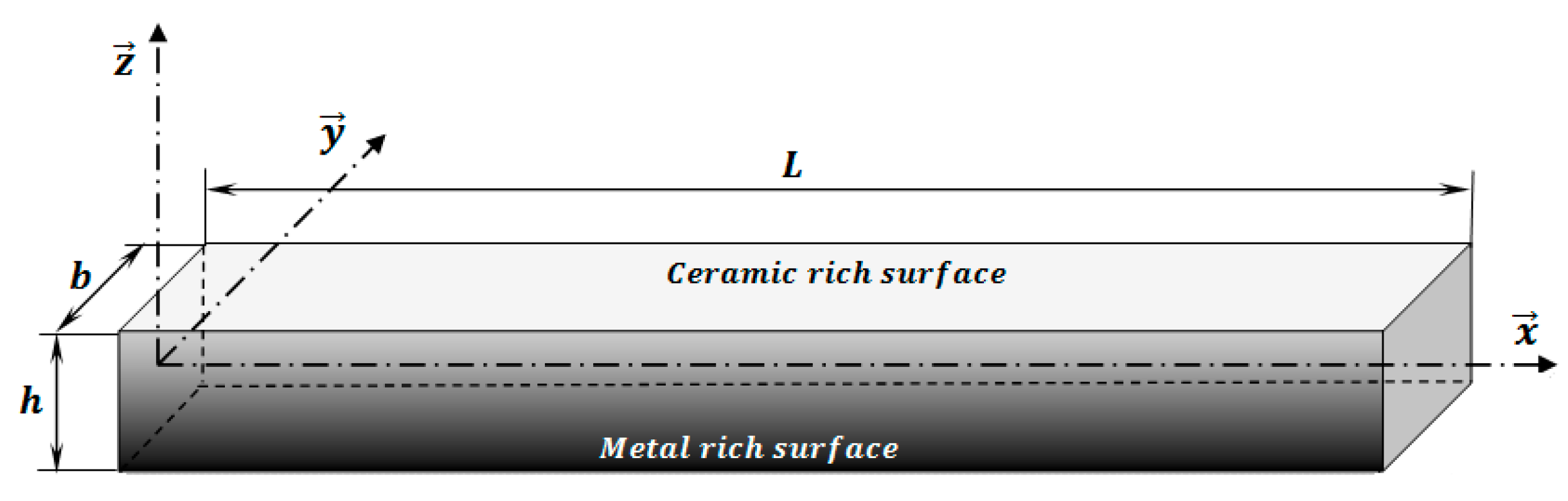
Figure 1 shows the proposed model for this study. It is a thick FG beam with length , rectangular cross-section, width and height .
The FG beam is composed of a combination of metal and ceramics whose combination changes from the top surface purely ceramic to the bottom surface completely metallic. The beam material effective characteristic is assumed to changes through the FG beam thickness about the volume ratio and the characteristics of the constituent materials. It is formulated by the law of mixing as follow:
are Young’s modulus, mass density and Poisson’s coefficient, respectively. Variation of is generally small, so it remains constant and are ceramic and metal volume proportions respectively, defined by [36]:
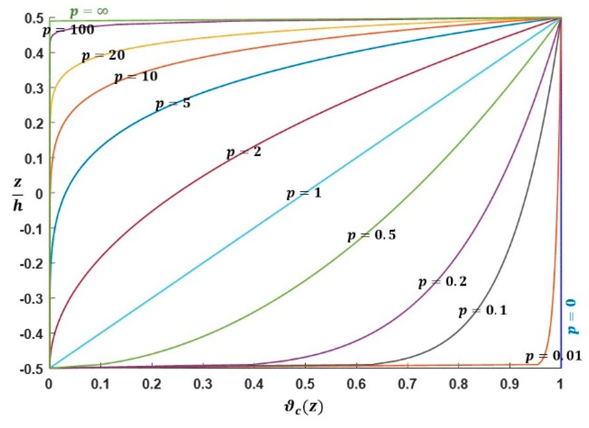
The gradient index , with determines the profile of the material in the FG beam thickness direction. It can be modified to obtain the optimum component materials distribution. The plot in Figure 2 shows the distribution of ceramic volume proportion across the FG beam thickness for various material indexes.
Each effective characteristic of the FG beam can be expressed as follows:
2.2. Displacement and Strain Fields
Transverse and axial displacements of the FG beam are expressed, according to the quasi-3D theory [35,37] as follow:
with,
- : Axial displacement;
- : Bending transverse displacement;
- : Shear transverse displacement;
- : Thickness-stretching displacement;
- and are four unknowns to be determined;
- and are the shape functions.
The strains are as follows:
The FG beam material follows Hooke’s law. So, linear elastic equation can be expressed as:
2.3. Calculation of Energies
- Strain energy:where, and are the stress resultants, specified as:By using Equation (7), the stress resultants given in Equation (9) can be expressed as:are the FG beam stiffness expressed, and are given by the Appendix A.
- Potential energy due the external transverse load applied:: External transverse loading.
- Kinetic energy:where are mass inertias, and are given by the Appendix A.
2.4. Governing Equation
To obtain the beam governing-equation, the Hamilton principle is applied as follows:
Substituting the expressions for and from Equations (8), (11) and (12) into Equation (13), the following system is obtained by integrating the parts and bringing together the coefficients of and :
Equation (14) can be expressed in terms of displacement of and by using Equation (10) as follows:
2.5. Analytical Solution for a Simple Supported Functionally Graded Beam (S-S FG Beam)
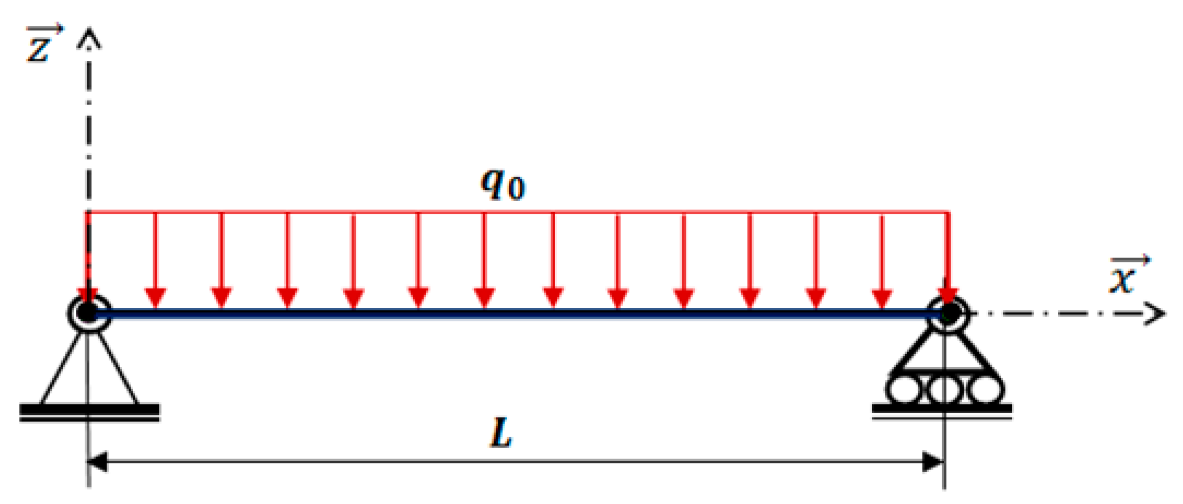
In this section, the analytical solution is given for the case of Simply Supported Functionally Graded beam presented in Figure 3 (S-S FG beam) under the uniform load distributed over its entire length.
Analytical solutions of the motion equations are provided, based on Navier type solutions. The following displacements and are assumed to be combinations of known trigonometric functions which satisfy the boundary conditions and unknown coefficients to be determined for each value of .
is the eigenfrequency associated with the nth eigenmode, , and and are the unknown coefficients.
The following boundary conditions are imposed for a beam with two ends simply supported.
The assumed mechanical transverse load is developed in a sinusoidal Fourier series as:
The coefficients are provided below for some loads.
- Sinusoidal distribution case:
- Uniform distribution case:
So, analytical solutions may be reached from the eigenvalues system below for any fixed value of :
In the static problem case, Equation (24) becomes:
and are given by the Appendix A.
3. Numerical Results and Discussion
In this part, a uniform transverse load is applied to the S-S FG beam. Numerical examples are proposed first to validate the model presented above and assess its accuracy. The FG beam material is composed by (alumina) and (aluminum). The material characteristics of the corresponding components are listed in Table 1.
The dimensionless form is used as follows:
A numerical example set out in Table 2 is performed for various material indexes (p) and slenderness ration (L/h) to validate the present model. The results obtained by this theory concerning displacements and the stresses for (L/h = 5, 20) are compared with those of the analytical solution provided by Li et al. [39]. The following shape function based on Reddy beam theory is used:
3.1. Static Analysis
Table 2 reveals that the present theory is with good agreement compared to the results obtained by Li et al. [39] and thus confirm the validation of the proposed method. It can also be seen that the CBT model, which omits shear deformation effects under-estimates displacements and stresses of the thick FG beams.
The impact of the material index (p) and slenderness ratio (L/h) on transverse and axial displacements, axial and shear stresses of S-S FG beam under uniform load are illustrated in Table 2 and Table 3. In general, all shear deformation beam models give almost identical results, except for the case of transverse shear stress . It can be explained by the different transverse shear strain shape functions g(z) used in each models. It can be seen that those both displacements and axial stress of S-S FGB increases with increasing the power-law exponent (p). This is due to the fact that higher values of power law index (p) correspond to high portion of metal in comparison with the ceramic part, thus makes such FG beams more flexible. In fact, when p = 0, beam is made from fully ceramic and has the smallest displacements. By increasing the exponent (p) of the power law, the constitution of the FGB changes from an all-metal beam to a beam mixing ceramic and metal, then to an all-metallic beam (p→∞). Therefore, the percentage of metal phase increases and the beam becomes more flexible, which leads to increased displacements. However, the effect of the material index on the shear stress is negligible since the value of this stress is negligible compared to the axial stress.
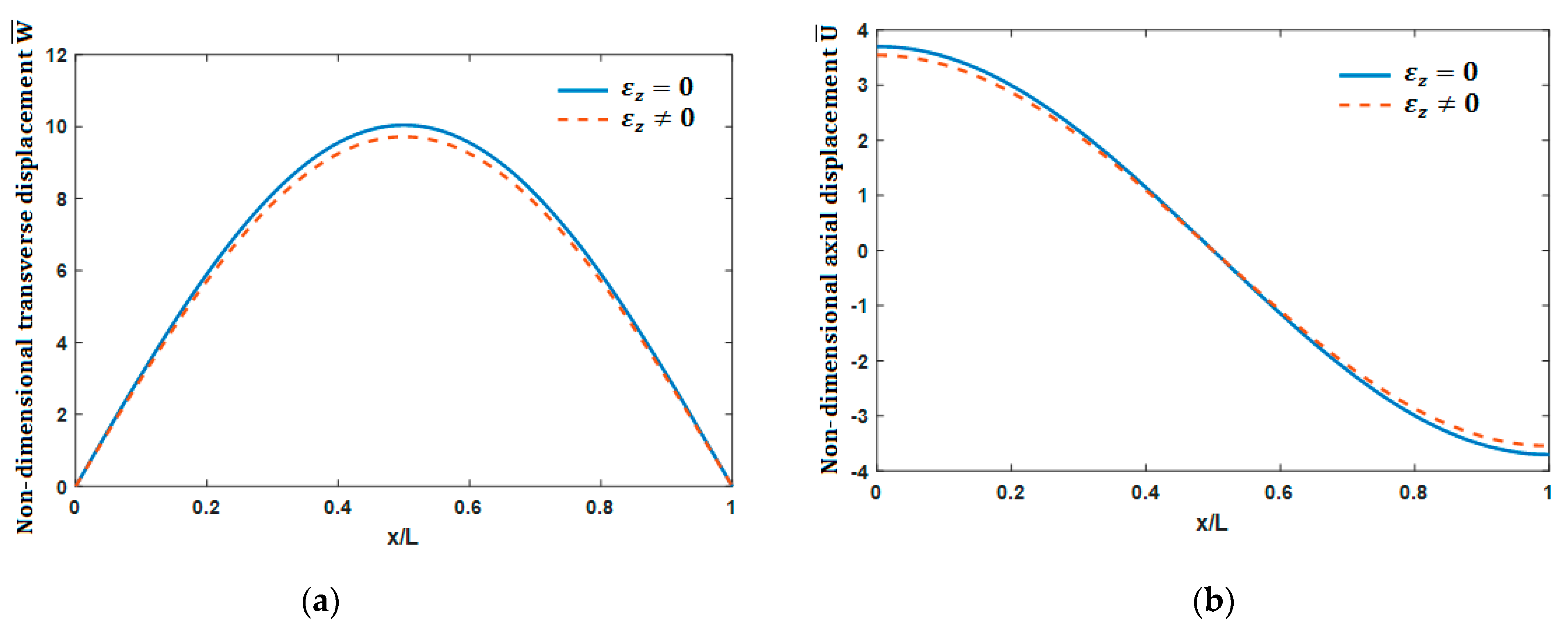
To investigate again the effects of the thickness stretching on displacements, a comparison between the non-dimensional displacements of the beam obtained from the present model with and without thickness stretching is made in Figure 4a,b for the transverse and axial displacements, respectively, for (L/h = 5) and (p = 5). The difference between the two curves is seen. It is large out in the middle of the beam and becomes zero at the ends for the transverse displacement and becomes zero out in the middle of the beam for the axial displacement, unlike for the axial displacement, which is large at the ends and vanishes out in the middle of the beam.
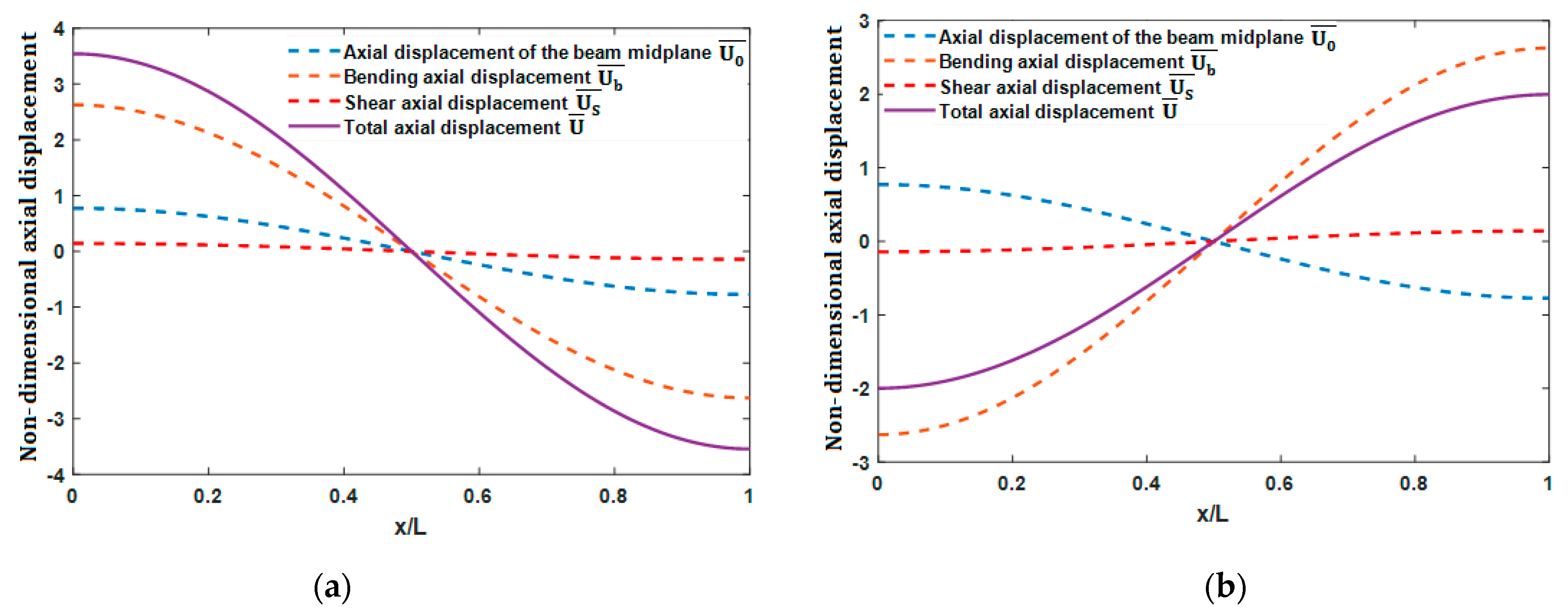
Effect of shear on the evolution of non-dimensional axial displacement along the beam on the upper and lower beam faces is evaluated from Figure 5a,b for (L/h = 5) and (p = 5). We notice that shear have a very slight effect on the axial displacement. It can also be seen that shear is maximum at the ends and zero at the mid-span of the beam.
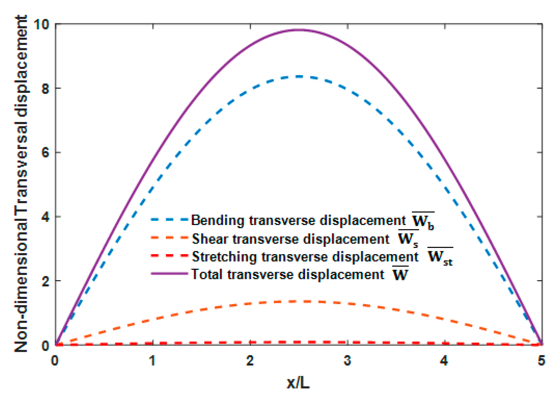
In the second examination and analysis example, effects of shear and thickness stretching on the non-dimensional axial and transverse displacements of the S-S FG beam are evaluated in Figure 6, for (L/h = 5) and (p = 5). It is obvious from these figures that the shear effect is more important on the two displacements, and it is greatest than the effect of thickness stretching for the transverse displacement. It means that the inclusion of shear deformation effect leads to an increase in the deflections and more pronounced for short beams. So, the shear effect on the displacements cannot be neglected, especially for the thick beams.
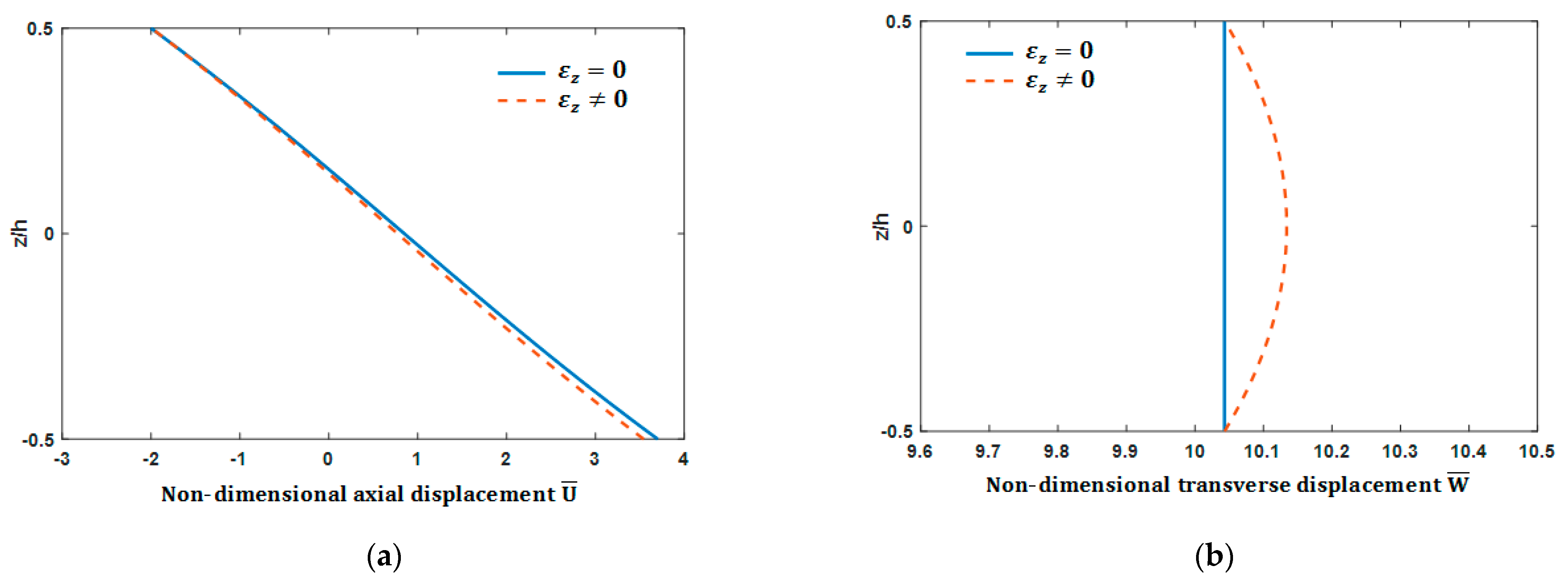
In Figure 7a,b, the evolution of non-dimensional (a) in-plane displacement at the end and (b) transverse displacement at mid-span through the FG beam thickness under uniform load is presented for (L/h = 5) and (p = 5). A slight difference appears for this shortest beam. It is seen that the maximum displacement is at the bottom of the beam for axial displacement and the median plane for transverse displacement. This is due to the consideration of the thickness stretching .
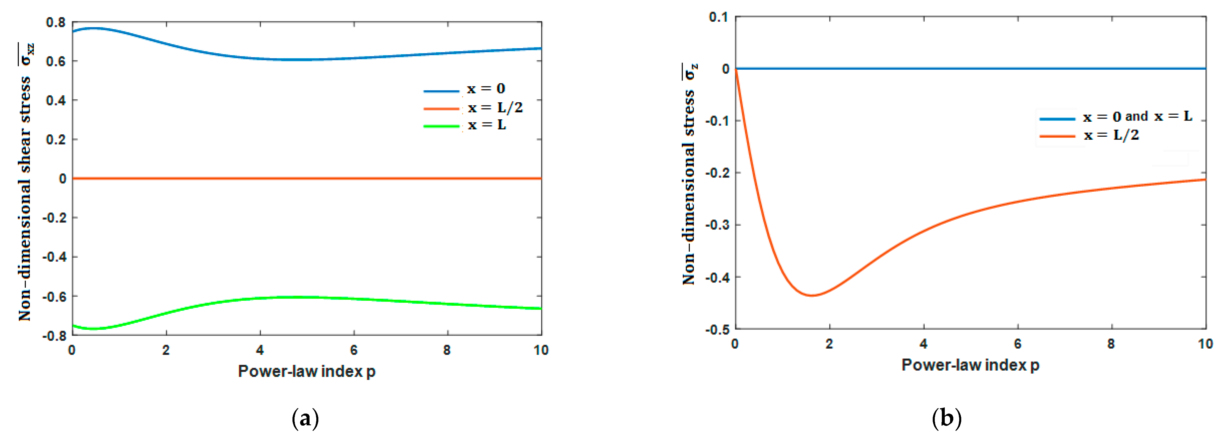
Figure 8a illustrates the evolution of the non-dimensional transverse shear stress and Figure 8b shows the stress due to the thickness stretching versus the power-law index for (L/h = 5). All curves display the material index dependence of the stresses. It is clear that stress due to the thickness stretching exhibits low but not negligible values compared with those of the transverse shear stress.
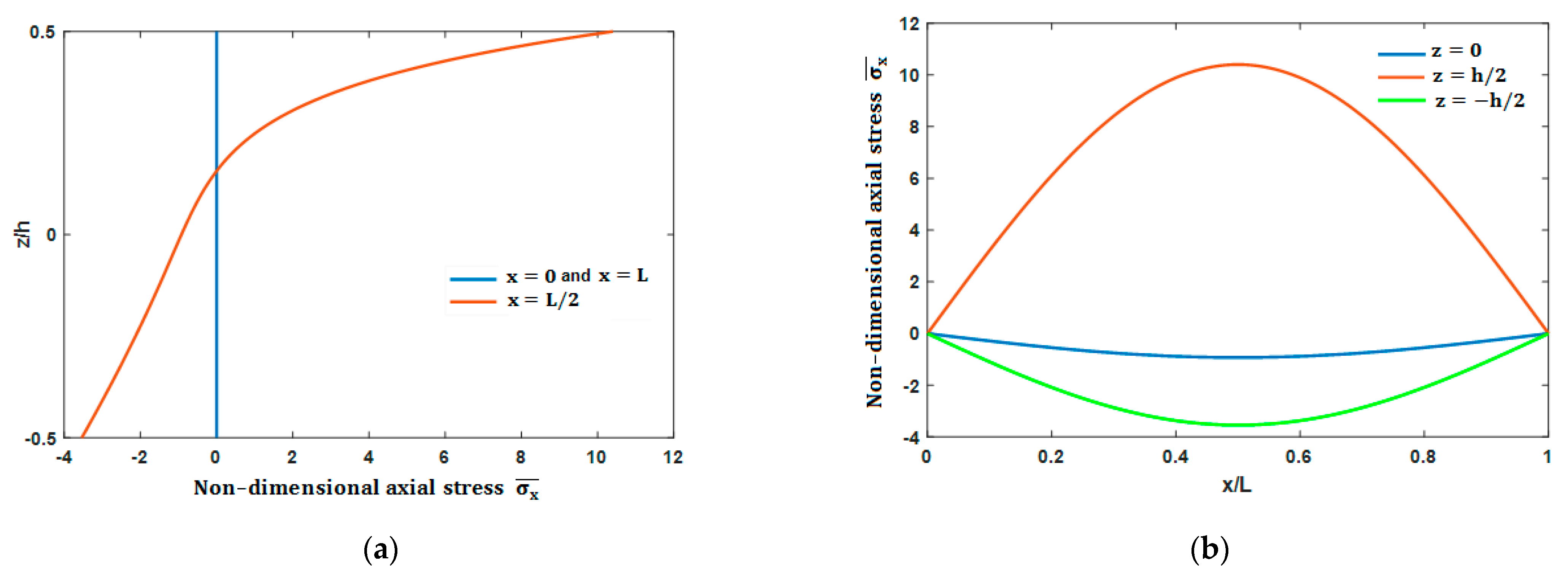
Variations of the non-dimensional axial stress across the depth and versus non-dimensional length of the FGB are presented in Figure 9a,b for (L/h = 5) and (p = 5). The axial stress is zero at the end edges, but it is maximum at the middle of the beam, and the upper beam face is stretched. On the other hand, the lower face is compressed. Extension stress at the upper beam face is higher than the compressive stress at the lower face because at the upper face, the beam is ceramic-rich, whereas, at the lower face, it is metal-rich. It is observed that the neutral plan with zero axial stress is moved upwards relative to the middle position. This is due to the non-homogeneous material of the FG beam (p = 5).
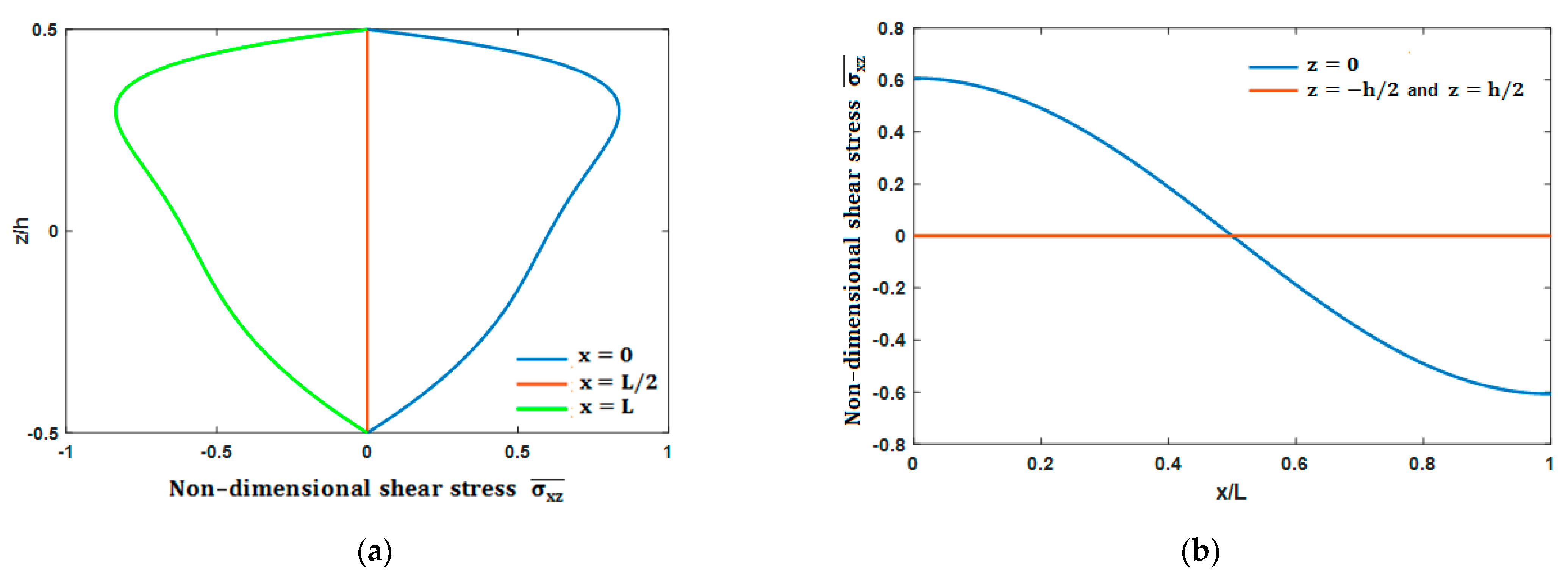
Figure 10a,b plots the distributions of the non-dimensional shear stress through thethickness and versus the non-dimensional length of the FG beam, respectively, for (L/h = 5) and (p = 5). These figures reveal that the shear stress reaches its maximum value at the beam ends but with opposite signs. It is cancelled in the middle of the beam on the neutral plane and the lower and upper faces. As a result, the conditions of non-shearing on both the lower and upper faces of the beam are satisfied.
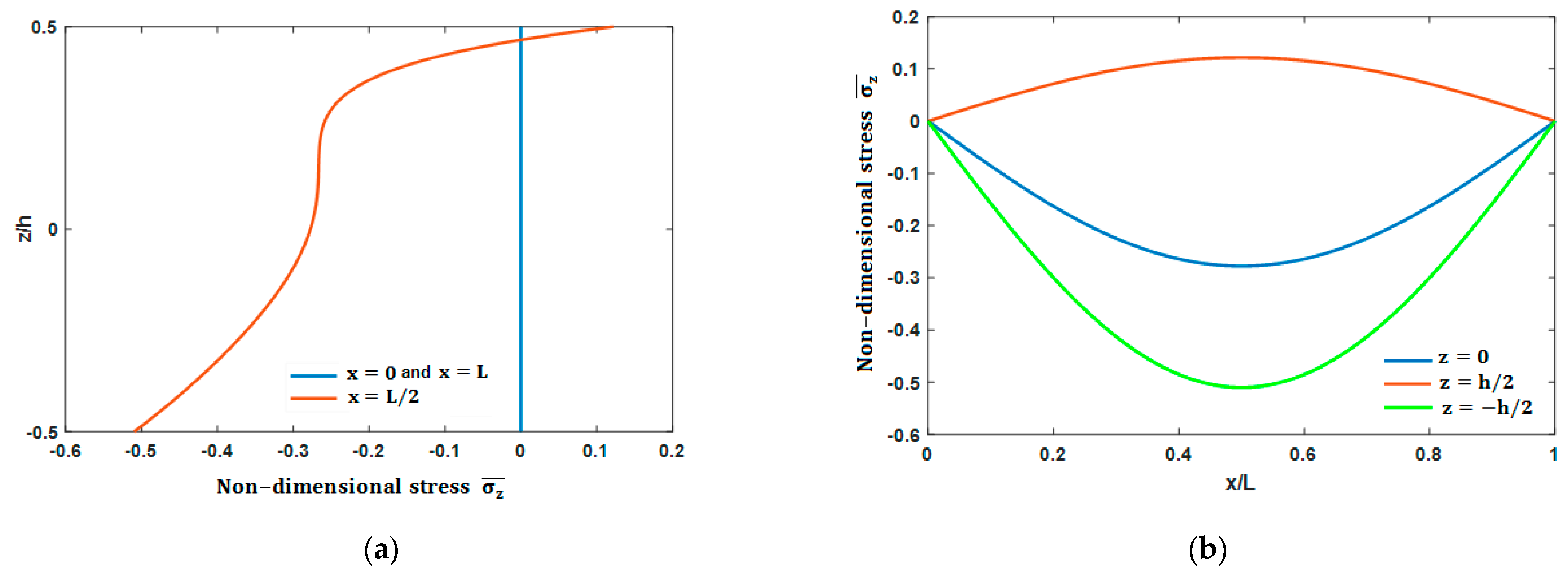
The thickness-stretching impact on the stresses is evaluated in Figure 11a,b for (L/h = 5) and (p = 5). It may be seen that is equal to zero at both end edges. Its highest value is reached in the middle of the beam. The upper beam face is stretched. On the other hand, the lower face is compressed. Compressive stress at the FG beam’s lower face is higher than extension stress at the upper face.
3.2. Vibration Analysis
Table 4 summarizes dimensionless frequencies associated with the first, second and third mode shapes of the S-S FG beam for various (L/h) ratio and material parameter (p).
Again, the results obtained by the present model, when the thickness-stretching is neglected, correlate closely with these obtained by the HSDT solution [30]. HSDT model under-estimates the frequencies of thick FG beams. This is due to the stretching of de the beam thickness omitted by the HSDT formulation in the thick FG beams case. It is emphasized that in the HSDT [30] formulation, the unknowns number is greater than this provided by the present model.
The dimensionless frequency variation versus material parameter for an (L/h = 5) with and without taking a count of the thickness stretching is plotted in Figure 12a. The plot showed that increasing (p) leads to a decrease of the frequencies. The highest frequency is achieved for (p = 0, completely ceramic beam), and the lowest for (p→∞, completely metal beam). This can be explained by the fact that the increase in (p) leads to a decrease in the amount of ceramic in the mixture, which is replaced by the metal, resulting in the decrease of Young’s modulus that makes the beam more flexible. Additionally, in this kind of composition, the density of the metal is greater than the density of ceramic and the total mass of the FG beam increases by increasing the metal proportion in the beam, which makes it softer. Therefore, the frequency decreases by increasing the material index (p).
The offset between both curves shows difference between the frequencies of both models with and without thickness stretching is significant for higher modes and for small slenderness ratios (L/h) (sees also Table 4 and Table 5). This is due to the effects of normal deformation. This effect leads to an increase of the vibration frequencies, and this increase is amplified at higher vibration modes and for small slenderness ratios. It implies that the normal deformation beam model should be employed for a better prediction of the frequencies instead of the model which neglects the effects of transverse normal deformation. It is seen that the frequencies are under-estimated when thickness stretching is omitted.
The impact of the slenderness ratio (L/h) on the frequencies is shown in Figure 12b and Table 4 and Table 5. It is seen that an increase of slenderness ration (L/h) leads to an increase of frequencies, and this increase is amplified at higher vibration modes. The frequencies tend to increase when the beam becomes shorter (or thicker).
4. Conclusions
In this paper, a refined beam theory is performed for bending vibratory analysis of the thick FG beams, taking into consideration thickness-stretching. The transverse displacement is assumed to be the sum of three components, bending, shear and stretching of the thickness. This leads to reducing the unknown’s number of parameters, therefore the number of governing equations. According to a mixing law, the FG beam effective material characteristics are supposed to change continuously along the thickness direction depending on the volume proportion of the constituents. The governing equations are obtained from Hamilton’s principle and are solved by using Navier-solutions.
Both the analytical and numerical results obtained in this article agree with those obtained using other theories with more unknown parameters. Sensitivity analysis has been performed for the thickness-stretching, the material parameter and the beam-slenderness. For this investigation, the shortest beams exhibited the greatest thickness-stretching impact, and this needs to be taken into consideration in more physically realistic simulations. Both geometry and material parameters affect the vibrational responses of the FG beams. Finally, it is observed that the proposed higher order shear and normal deformation theory is not only accurate but also provides an elegant and easily implementable approach for simulating bending and vibration behaviors of FGM beams, of relevance for example in spacecraft thermo-structural design. The formulation lends itself particularly well to finite element simulations and also to other numerical methods employing symbolic computation for beam bending problems, which will be considered in the near future. Further applications of our refined FG beam are planned in another contribution to consolidate our approach.
Author Contributions
Conceptualization, Y.B. and N.L.; methodology, Y.B., N.L. and D.B.; software, Y.B. and N.L.; validation, N.L. and D.B.; formal analysis, Y.B.; investigation, Y.B., N.L. and D.B.; resources, Y.B. and N.L.; data curation, Y.B. and N.L.; writing—original draft preparation, Y.B. and D.B.; writing—review and editing, D.B.; visualization, Y.B. and N.L.; supervision, N.L. and D.B.; project administration, N.L. and D.B. All authors have read and agreed to the published version of the manuscript.
Funding
This research received no external funding.
Conflicts of Interest
The authors declare no conflict of interest.
Appendix A
References
- Koizumi, M. FGM activities in Japan. Compos. Part B Eng. 1997, 28, 1–4. [Google Scholar] [CrossRef]
- Moita, J.S.; Araújo, A.L.; Correia, V.F.; Soares, C.M.M. Mechanical and thermal buckling of functionally graded axisymmetric shells. Compos. Struct. 2021, 261. [Google Scholar] [CrossRef]
- Moleiro, F.; Madeira, J.F.A.; Carrera, E.; Reddy, J.N. Design optimization of functionally graded plates under thermo-mechanical loadings to minimize stress, deformation and mass. Compos. Struct. 2020, 245. [Google Scholar] [CrossRef]
- Gul, U.; Aydogdu, M.; Karacam, F. Dynamics of a functionally graded Timoshenko beam considering new spectrums. Compos. Struct. 2019, 207. [Google Scholar] [CrossRef]
- Li, X.F. A unified approach for analyzing static and dynamic behaviors of functionally graded Timoshenko and Euler–Bernoulli beams. J. Sound Vib. 2008, 318, 1210–1229. [Google Scholar] [CrossRef]
- Benatta, M.A.; Mechab, I.; Tounsi, A.; Bedia, E.A.A. Static analysis of functionally graded short beams including warping and shear deformation effects. Comput. Mater. Sci. 2008, 44, 765–773. [Google Scholar] [CrossRef]
- Ben-Oumrane, S.; Abedlouahed, T.; Ismail, M.; Mohamed Bachir, B.; Mustapha, M.; El Abbas, A.B. A theoretical analysis of flexional bending of Al/Al2O3 S-FGM thick beams. Comput. Mater. Sci. 2009, 44, 1344–1350. [Google Scholar] [CrossRef]
- Sina, S.A.; Navazi, H.M.; Haddadpour, H. An analytical method for free vibration analysis of functionally graded beams. Mater. Des. 2009, 30, 741–747. [Google Scholar] [CrossRef]
- Şimşek, M. Static analysis of a functionally graded beam under a uniformly distributed load by Ritz method. Int. J. Eng. Appl. Sci. 2009, 1, 1–11. [Google Scholar]
- Ghayesh, H.M. Vibration analysis of shear-deformable AFG imperfect beams. Compos. Struct. 2018, 200, 910–920. [Google Scholar] [CrossRef]
- Menaa, R.; Tounsi, A.; Mouaici, F.; Mechab, I.; Zidi, M.; Bedia, E.A.A. Analytical solutions for static shear correction factor of functionally graded rectangular beams. Mech. Adv. Mater. Struct. 2012, 19, 641–652. [Google Scholar] [CrossRef]
- Yaghoobi, H.; Yaghoobi, P. Buckling analysis of sandwich plates with FGM face sheets resting on elastic foundation with various boundary conditions: An analytical approach. Meccanica 2013, 48, 2019–2035. [Google Scholar] [CrossRef]
- Feldman, E.; Aboudi, J. Buckling analysis of functionally graded plates subjected to uniaxial loading. Compos. Struct. 1997, 38, 29–36. [Google Scholar] [CrossRef]
- Abrate, S. Functionally graded plates behave like homogeneous plates. Compos. Part B 2008, 39, 151–158. [Google Scholar] [CrossRef]
- Mahdavian, M. Buckling analysis of simply-supported functionally graded rectangular plates under non-uniform in-plane compressive loading. J. Solid Mech. 2009, 1, 213–225. [Google Scholar]
- Mohammadi, M.; Saidi, A.R.; Jomehzadeh, E. Levy solution for buckling analysis of functionally graded rectangular plates. Appl. Compos. Mater. 2010, 17, 81–93. [Google Scholar] [CrossRef]
- Della Croce, L.; Venini, P. Finite elements for functionally graded Reissner–Mindlin plates. Comput. Methods Appl. Mech. Eng. 2004, 193, 705–725. [Google Scholar] [CrossRef]
- Yang, J.; Liew, K.M.; Kitipornchai, S. Second-order statistics of the elastic buckling of functionally graded rectangular plates. Compos. Sci. Technol. 2005, 65, 1165–1175. [Google Scholar] [CrossRef]
- Zhao, X.; Lee, Y.Y.; Liew, K.M. Mechanical and thermal buckling analysis of functionally graded plates. Compos. Struct. 2009, 90, 161–171. [Google Scholar] [CrossRef]
- Loy, C.T.; Lam, K.Y.; Reddy, J.N. Vibration of functionally graded cylindrical shells. Int. J. Mech. Sci. 1999, 41, 309–324. [Google Scholar] [CrossRef]
- Pradhan, S.C.; Loy, C.T.; Lam, K.Y.; Reddy, J.N. Vibration characteristics of functionally graded cylindrical shells under various boundary conditions. Appl. Acoust. 2000, 61, 111–129. [Google Scholar] [CrossRef]
- Strozzi, M.; Pellicano, F. Nonlinear vibrations of functionally graded cylindrical shells. Thin Walled Struct. 2013, 67, 63–77. [Google Scholar] [CrossRef]
- Moleiro, F.; Correia, V.M.F.; Araújo, A.L.; Soares, C.M.M.; Ferreira, A.J.M.; Reddy, J.N. Deformations and stresses of multilayered plates with embedded functionally graded material layers using a layerwise mixed model. Compos. Part B Eng. 2019, 156. [Google Scholar] [CrossRef]
- Thai, H.T.; Vo, T.P. Bending and free vibration of functionally graded beams using various higher-order shear deformation beam theories. Int. J. Mech. Sci. 2012, 62. [Google Scholar] [CrossRef] [Green Version]
- Ebrahimi, F.; Jafari, A. A Higher-Order Thermomechanical Vibration Analysis of Temperature-Dependent FGM Beams with Porosities. J. Eng. 2016, 2016. [Google Scholar] [CrossRef] [Green Version]
- Aydogdu, M.; Taskin, V. Free vibration analysis of functionally graded beams with simply supported edges. Mater. Des. 2007, 28, 1651–1656. [Google Scholar] [CrossRef]
- Şimşek, M. Buckling of Timoshenko beams composed of two-dimensional functionally graded material (2D-FGM) having different boundary conditions. Compos. Struct. 2016, 149. [Google Scholar] [CrossRef]
- Patil, R.; Joladarashi, S.; Kadoli, R. Studies on free and forced vibration of functionally graded back plate with brake insulator of a disc brake system. Arch. Appl. Mech. 2020, 90. [Google Scholar] [CrossRef]
- Zhong, Z.; Yu, T. Analytical solution of a cantilever functionally graded beam. Compos. Sci. Technol. 2007, 67. [Google Scholar] [CrossRef]
- Larbi, L.O.; Kaci, A.; Houari, M.S.A.; Tounsi, A. An efficient shear deformation beam theory based on neutral surface position for bending and free vibration of functionally graded beams. Mech. Based Des. Struct. Mach. 2013, 41. [Google Scholar] [CrossRef]
- Larbi, L.O.; Hadji, L.; Meziane, M.A.A.; Bedia, E.A.A. An analytical solution for free vibration of functionally graded beam using a simple first-order shear deformation theory. Wind Struct. Int. J. 2018, 27. [Google Scholar] [CrossRef]
- Bouremana, M.; Houari, M.S.A.; Tounsi, A.; Kaci, A.; Bedia, E.A.A. A new first shear deformation beam theory based on neutral surface position for functionally graded beams. Steel Compos. Struct. 2013, 15. [Google Scholar] [CrossRef]
- Fekrar, A.; Houari, M.S.A.; Tounsi, A.; Mahmoud, S.R. A new five-unknown refined theory based on neutral surface position for bending analysis of exponential graded plates. Meccanica 2014, 49. [Google Scholar] [CrossRef]
- Osofero, A.I.; Vo, T.P.; Nguyen, T.K.; Lee, J. Analytical solution for vibration and buckling of functionally graded sandwich beams using various quasi-3D theories. J. Sandw. Struct. Mater. 2016, 18. [Google Scholar] [CrossRef] [Green Version]
- Meradjah, M.; Kaci, A.; Houari, M.S.A.; Tounsi, A.; Mahmoud, S.R. A new higher order shear and normal deformation theory for functionally graded beams. Steel Compos. Struct. 2015, 18. [Google Scholar] [CrossRef]
- Praveen, G.N.; Reddy, J.N. Nonlinear transient thermoelastic analysis of functionally graded ceramic-metal plates. Int. J. Solids Struct. 1998, 35. [Google Scholar] [CrossRef]
- Minh, P.P.; Manh, D.T.; Duc, N.D. Free vibration of cracked FGM plates with variable thickness resting on elastic foundations. Thin Walled Struct. 2021, 161. [Google Scholar] [CrossRef]
- Tornabene, F. Free vibration analysis of functionally graded conical, cylindrical shell and annular plate structures with a four-parameter power-law distribution. Comput. Methods Appl. Mech. Eng. 2009, 198. [Google Scholar] [CrossRef]
- Li, X.F.; Wang, B.L.; Han, J.C. A higher-order theory for static and dynamic analyses of functionally graded beams. Arch. Appl. Mech. 2010, 80. [Google Scholar] [CrossRef]
Figure 1.
The geometry of the FG beam.

Figure 2.
Ceramic volume proportion profile across the FG beam thickness, for different material indexes.
Figure 2.
Ceramic volume proportion profile across the FG beam thickness, for different material indexes.

Figure 3.
Simply Supported Functionally Graded beam (S-S FG beam) under uniform load.

Figure 4.
Thickness stretching effect on the non-dimensional transverse (a) and axial displacements (b).
Figure 4.
Thickness stretching effect on the non-dimensional transverse (a) and axial displacements (b).

Figure 5.
Shear effect on axial displacement a long of the FGB on: (a) lower beam face and (b) upper beam face.
Figure 5.
Shear effect on axial displacement a long of the FGB on: (a) lower beam face and (b) upper beam face.

Figure 6.
Shear and stretching effects on the transverse displacement.

Figure 7.
Non-dimensional: (a) axial displacement, and (b) mid-span deflection through the FG beam thickness.
Figure 7.
Non-dimensional: (a) axial displacement, and (b) mid-span deflection through the FG beam thickness.

Figure 8.
Non-dimensional: (a) Shear stress , (b) stress due to the thickness stretching versus the material parameter.
Figure 8.
Non-dimensional: (a) Shear stress , (b) stress due to the thickness stretching versus the material parameter.

Figure 9.
distributions: (a) over the FG beam thickness, (b) versus the FG beam non-dimensional length.
Figure 9.
distributions: (a) over the FG beam thickness, (b) versus the FG beam non-dimensional length.

Figure 10.
distributions: (a) over the FG beam thickness, (b) versus the FG beam non-dimensional length.
Figure 10.
distributions: (a) over the FG beam thickness, (b) versus the FG beam non-dimensional length.

Figure 11.
distributions: (a) over the FG beam thickness; (b) versus the FG beam non-dimensional length.
Figure 11.
distributions: (a) over the FG beam thickness; (b) versus the FG beam non-dimensional length.

Figure 12.
Effect of (a) the material parameter and (b) slenderness ratio (L/h) on the dimensionless fundamental frequency of the S-S FG beam.
Figure 12.
Effect of (a) the material parameter and (b) slenderness ratio (L/h) on the dimensionless fundamental frequency of the S-S FG beam.


Table 1.
Material characteristics of and [38].
Table 1.
Material characteristics of and [38].
| Components | |||
|---|---|---|---|
| Ceramic (alumina ) | 0.3 | 380 | 3960 |
| Metal (aluminium ) | 0.3 | 70 | 2702 |
Table 2.
Comparison of non-dimensional transverseand axial displacements, axial and shear stresses of S-S FG beam for various material indexes and slenderness ratio (L/h).
Table 2.
Comparison of non-dimensional transverseand axial displacements, axial and shear stresses of S-S FG beam for various material indexes and slenderness ratio (L/h).
| Theory | |||||||||
|---|---|---|---|---|---|---|---|---|---|
| Li et al. [39] | 3.1657 | 0.9402 | 3.8020 | 0.7500 | 2.8962 | 0.2306 | 15.0130 | 0.7500 | |
| CBT | 2.8783 | 0.9211 | 3.7500 | - | 2.8783 | 0.2303 | 15.0000 | - | |
| Present | 3.1681 | 0.9406 | 3.7919 | 0.7503 | 2.8962 | 0.2306 | 15.0129 | 0.7429 | |
| Li et al. [39] | 4.8292 | 1.6603 | 4.9925 | 0.7676 | 4.4645 | 0.4087 | 19.7005 | 0.7676 | |
| CBT | 4.4401 | 1.6331 | 4.9206 | - | 4.4401 | 0.4083 | 19.6825 | - | |
| Present | 4.8202 | 1.6653 | 4.9893 | 0.7674 | 4.4644 | 0.4087 | 19.7003 | 0.7599 | |
| Li et al. [39] | 6.2599 | 2.3045 | 5.8837 | 0.7500 | 5.8049 | 0.5686 | 23.2054 | 0.7500 | |
| CBT | 5.7746 | 2.2722 | 5.7959 | - | 5.7746 | 0.5680 | 23.1834 | - | |
| Present | 6.2475 | 2.2903 | 5.8797 | 0.7503 | 5.8049 | 0.5685 | 23.2052 | 0.7429 | |
| Li et al. [39] | 9.7802 | 3.7089 | 8.1030 | 0.5790 | 8.8151 | 0.9133 | 31.8112 | 0.5790 | |
| CBT | 8.7508 | 3.6496 | 8.1329 | - | 8.7508 | 0.9124 | 31.7711 | - | |
| Present | 9.7787 | 3.6955 | 8.1099 | 0.5867 | 8.8181 | 0.9134 | 31.8127 | 0.5998 | |
| Li et al. [39] | 10.8979 | 3.8860 | 9.7063 | 0.6436 | 9.6879 | 0.9536 | 38.1372 | 0.6436 | |
| CBT | 9.6072 | 3.8097 | 9.5228 | - | 9.6072 | 0.9524 | 38.0913 | - | |
| Present | 10.8847 | 3.8780 | 9.7086 | 0.6645 | 9.6905 | 0.9536 | 38.1383 | 0.6572 | |
Table 3.
Effect of slenderness ratio (L/h) and material index (p) on non-dimensional transverse and axial displacements, axial and shear stresses of S-S FG beam.
Table 3.
Effect of slenderness ratio (L/h) and material index (p) on non-dimensional transverse and axial displacements, axial and shear stresses of S-S FG beam.
| 4.7289 | 2.5728 | 1.6588 | 0.7452 | 3.0406 | 0.6703 | 5.2947 | 0.7504 | 2.9408 | 0.3888 | 9.0248 | 0.7507 | |
| 6.9470 | 4.4740 | 2.1876 | 0.7625 | 4.6618 | 1.1865 | 6.9507 | 0.7674 | 4.5269 | 0.6890 | 11.8440 | 0.7677 | |
| 8.9036 | 6.1551 | 2.5866 | 0.7452 | 6.0522 | 1.6492 | 8.1898 | 0.7504 | 5.8838 | 0.9583 | 13.9523 | 0.7507 | |
| 15.667 | 10.0137 | 3.6884 | 0.6009 | 9.3520 | 2.6521 | 11.2654 | 0.6070 | 8.9777 | 1.5398 | 19.1450 | 0.6073 | |
| 18.146 | 10.6328 | 4.3860 | 0.6581 | 10.345 | 2.7727 | 13.4960 | 0.6648 | 9.8830 | 1.6082 | 22.9475 | 0.6652 | |
Table 4.
Comparison of the S-S FG beam frequencies for some values of and .
| Mode | Theory | |||||||
|---|---|---|---|---|---|---|---|---|
| 0 | 0.5 | 1 | 5 | 10 | ||||
| 5 | 1 | HSDT [30] | 5.1530 | 4.4110 | 3.9900 | 3.4000 | 3.2810 | |
| Present | 5.1527 | 4.4107 | 3.9904 | 3.4012 | 3.2816 | |||
| 5.1516 | 4.4230 | 4.0169 | 3.4310 | 3.2984 | ||||
| 2 | HSDT [30] | 17.8840 | 15.4610 | 14.0120 | 11.5350 | 11.0220 | ||
| Present | 17.8812 | 15.4588 | 14.0100 | 11.5431 | 11.0240 | |||
| 17.8900 | 15.5052 | 14.0978 | 11.6348 | 11.0785 | ||||
| 3 | HSDT [30] | 34.2250 | 29.8490 | 27.1080 | 21.6990 | 20.7530 | ||
| Present | 34.2097 | 29.8382 | 27.0979 | 21.7158 | 20.5561 | |||
| 34.2975 | 29.9670 | 27.2813 | 21.8884 | 20.6748 | ||||
| 20 | 1 | HSDT [30] | 5.4600 | 4.6510 | 4.2050 | 3.6480 | 3.5390 | |
| Present | 5.4603 | 4.6511 | 4.2051 | 3.6485 | 3.5390 | |||
| 5.4602 | 4.6657 | 4.2351 | 3.6835 | 3.5595 | ||||
| 2 | HSDT [30] | 21.5730 | 18.3960 | 16.6340 | 14.3730 | 13.9260 | ||
| Present | 21.5732 | 18.3962 | 16.6344 | 14.3746 | 13.9263 | |||
| 21.5710 | 18.4520 | 16.7511 | 14.5094 | 14.0043 | ||||
| 3 | HSDT [30] | 47.5940 | 40.6530 | 36.7690 | 31.5720 | 30.5340 | ||
| Present | 47.5930 | 40.6526 | 36.7679 | 31.5780 | 30.5369 | |||
| 47.5841 | 40.7709 | 37.0192 | 31.8649 | 30.7005 | ||||
Table 5.
Effect of slenderness ratio (L/h) on non-dimensional t fundamental frequency of the S-S FG beam for various material indexes.
Table 5.
Effect of slenderness ratio (L/h) on non-dimensional t fundamental frequency of the S-S FG beam for various material indexes.
| Mode | Theory | |||||||
|---|---|---|---|---|---|---|---|---|
| 0 | ||||||||
| 2 | 1 | Present | 4.1229 | 3.5811 | 3.2488 | 2.6369 | 2.5066 | |
| 4.1288 | 3.5939 | 3.2697 | 2.6578 | 2.5199 | ||||
| 2 | Present | 11.2755 | 9.9531 | 9.0776 | 7.0387 | 6.5825 | ||
| 11.3606 | 10.0311 | 9.1548 | 7.0986 | 6.6339 | ||||
| 3 | Present | 18.8329 | 16.7556 | 15.3540 | 11.7045 | 10.8540 | ||
| 19.0593 | 16.9370 | 15.5040 | 11.8133 | 10.9627 | ||||
| 7 | 1 | Present | 5.3051 | 4.5303 | 4.0972 | 3.5223 | 3.4072 | |
| 5.3043 | 4.5436 | 4.1254 | 3.5545 | 3.4256 | ||||
| 2 | Present | 19.5009 | 16.7623 | 15.1752 | 12.7469 | 12.2452 | ||
| 19.4986 | 16.8082 | 15.2720 | 12.8527 | 12.3049 | ||||
| 3 | Present | 39.3228 | 34.0427 | 30.8609 | 25.3129 | 24.1409 | ||
| 39.3514 | 34.1495 | 31.0553 | 25.5131 | 24.2620 | ||||
| 12 | 1 | Present | 5.4202 | 4.6199 | 4.1772 | 3.6156 | 3.5045 | |
| 5.4198 | 4.6342 | 4.2068 | 3.6498 | 3.5244 | ||||
| 2 | Present | 20.9836 | 17.9355 | 16.2232 | 13.8997 | 13.4318 | ||
| 20.9793 | 17.9871 | 16.3331 | 14.0246 | 13.5027 | ||||
| 3 | Present | 44.9631 | 38.5796 | 34.9166 | 29.5118 | 28.4027 | ||
| 44.9542 | 38.6852 | 35.1425 | 29.7618 | 28.5434 | ||||
Publisher’s Note: MDPI stays neutral with regard to jurisdictional claims in published maps and institutional affiliations. |
© 2021 by the authors. Licensee MDPI, Basel, Switzerland. This article is an open access article distributed under the terms and conditions of the Creative Commons Attribution (CC BY) license (https://creativecommons.org/licenses/by/4.0/).
Share and Cite
MDPI and ACS Style
Boutahar, Y.; Lebaal, N.; Bassir, D. A Refined Theory for Bending Vibratory Analysis of Thick Functionally Graded Beams. Mathematics 2021, 9, 1422. https://doi.org/10.3390/math9121422
AMA Style
Boutahar Y, Lebaal N, Bassir D. A Refined Theory for Bending Vibratory Analysis of Thick Functionally Graded Beams. Mathematics. 2021; 9(12):1422. https://doi.org/10.3390/math9121422
Chicago/Turabian StyleBoutahar, Youssef, Nadhir Lebaal, and David Bassir. 2021. "A Refined Theory for Bending Vibratory Analysis of Thick Functionally Graded Beams" Mathematics 9, no. 12: 1422. https://doi.org/10.3390/math9121422
Note that from the first issue of 2016, this journal uses article numbers instead of page numbers. See further details here.