The Development of a Gracilis and Quadriceps Tendons Calibration Device for Uniaxial Tensile Tests


1
Mechanical Engineering Faculty in Slavonski Brod, University of Slavonski Brod, 35000 Slavonski Brod, Croatia
2
Faculty of Mechanical Engineering and Naval Architecture, University of Zagreb, 10002 Zagreb, Croatia
*
Author to whom correspondence should be addressed.
Machines 2021, 9(12), 364; https://doi.org/10.3390/machines9120364
Submission received: 8 November 2021
/
Revised: 22 November 2021
/
Accepted: 14 December 2021
/
Published: 17 December 2021
(This article belongs to the Section Bioengineering Technology)
Abstract
:To determine the biomechanical properties of the distal tendon of the gracilis muscle and the upper third of the quadriceps femoris muscle used for reconstruction of the medial patellofemoral ligament (MPFL), it is necessary to develop a calibration device for specimen preparation for uniaxial tensile tests. The need to develop this device also stems from the fact that there is currently no suitable regulatory or accurate protocol by which soft tissues such as tendons should be tested. In recent studies, various methods have been used to prepare test specimens, such as the use of different ratios of gauge lengths, different gripping techniques, etc., with the aim of obtaining measurable and comparable biomechanical tissue properties. Since tendons, as anisotropic materials, have viscoelastic properties, the guideline for manufacturing calibrator devices was the ISO 527-1:1993 standard, used for testing polymers, since they also have viscoelastic behaviour. The functionality of a calibrator device was investigated by preparing gracilis and quadriceps tendon samples. Fused deposition modeling (FDM) technology was used for the manufacturing of parts with complex geometry. The proposed calibrator could operate in two positions, horizontal and vertical. The maximum gauge length to be achieved was 60 mm, with the maximum tendon length of 120 mm. The average preparation time was 3 min per tendon. It was experimentally proven that it is possible to use a calibrator to prepare tendons for tensile tests. This research can help in the further development of soft tissue testing devices and also in the establishment of standards and exact protocols for their testing.
1. Introduction
Since tissues are composite materials (composed of different types of collagen fibres) and have anisotropic properties, their mechanical properties vary from point to point within the tissue, and their response to applied forces may be different in different directions [1]. In contrast to isotropic materials, anisotropic materials can be defined as materials whose physical properties, e.g., the modulus of elasticity, have different values in different directions in the object [2]. This also applies to the soft tissues of the human body. Depending on their shape, or rather their natural design, tissues exhibit anisotropy in the two-dimensional plane (e.g., skin) or in three-dimensional space (e.g., bone). How the physical properties are distributed depends on the collagen fibres in the tissue [3]. Tendons are soft tissues whose properties depend on the distribution of collagen fibres oriented along the tendon axis [4]. The mechanical properties of connective tissue structures depend on several factors, primarily their function and intended use. They depend on the structure and composition of the basic collagenous fibres, their distribution in the tissue, the content and distribution of elastic fibres in the tissue, and the content and molecular structure of the basic matrix.
These are therefore fibre-reinforced composite materials. Such a structure has viscous as well as elastic and partly plastic properties, depending on the degree and type of loading. Mechanical tests of connective tissue structures can be performed in vitro on cadaveric material, on material taken during surgery, amputation, etc., and in vivo, which is much more complex, on experimental animals or humans. In vitro experiments are controlled but differ in many ways from the actual conditions in humans, where traumatic rupture of tendons or ligaments occurs and only the consequences can be registered. The choice of shape and dimensions of the sample, method, and device for mechanical testing depends on their structure and structure. The sample, method, and test device will be different for the following structures [5]:
- Structures with more or less parallel fibres in the form of strips or ribbons—tendons and ligaments;
- Structures in the form of membranes, wherein the fibres create a two-dimensional network of different interrelationships of these fibres;
- Three-dimensional connective structures in which collagen fibres create a spatial network.
An example of the conducted study related to the structures in the form of membranes can be seen in [6] and for the three-dimensional connective structures in [7]. The tendons testing procedures are discussed below.
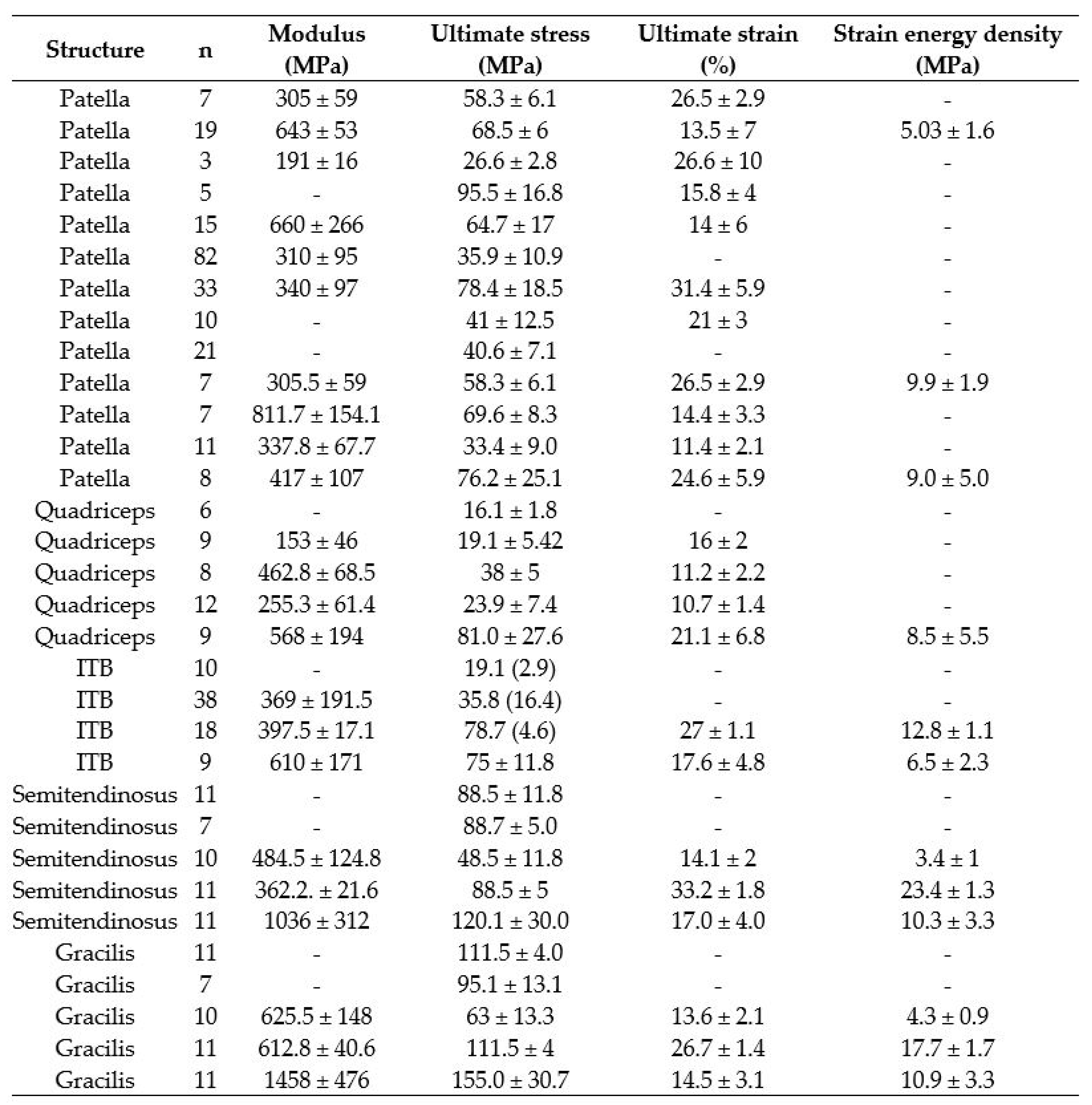
As far as conducting experiments is concerned, the requirements for laboratory equipment are very complex. Furthermore, there are still no standardised procedures for mechanical tendon testing. Instead, scientists proceed individually, using their previous experience or adopting the conditions for test setups from other researchers. In the end, the results of the experiments, when compared, show considerable differences, which makes it impossible to draw statistically concrete conclusions. An example of such results diversity can be seen in Figure 1 [8].
To proceed with the development of devices used for tissue testing, engineers must be familiar with the field of medicine and conduct experiments with tissues to be able to recognise the facts and see the space for further improvements. The result can be, e.g., a new list of requirements used for future new/improved product development. Therefore, in what follows, the key facts about tissue preparations before uniaxial tensile tests are elucidated. Generally, immediately after the dissection process from the cadaver’s body, the tendons or ligaments have to be stored by deep freezing. Authors in [9,10] stored the tissues at −18 °C, in [11,12] at −20 °C, in [13,14] at −80 °C. On the day of the test, frozen tissue samples have to be thawed at room temperature (23 ± 1 °C), followed by the determination of the main geometric properties such as tendon length, thickness, and the cross-section area. Since it is difficult to determine the correct cross-sectional area and shape of the tendons, a review of methods to measure tendon dimensions can be seen in [15]. Woo et al. [16] presented the development of an experimental approach of specimen preparation for uniaxial tensile tests using articular cartilage. They stated that the specimen length-to-width ratio of 4.25:1 can allow an even distribution of tensile stress in the measurement area. The use of this method can be also seen in the previously reported references [8,10]. The specimen length-to-width ratio of 10:1 was reported in [12] for human semitendinosus and gracilis tensile tests. There are several approaches to tissue testing without making any specific specimen preparations. However, the specimens have been tested in their natural form [17,18,19]. Scholze et al. [20] reported the ISO 527-2:1996 standard used as a cutting template to cut samples into a ‘dog-bone’ shape, and the same authors in [21] presented their work using the ISO 527-2:2019 standard with a change in the aspect ratio of 2:1. They have also presented the 3D-printed modular parts for sample preparation and mounting, fabricated using FDM technology. The tendon preparation has been carried out in a horizontal position. To our best knowledge, other devices for tendon preparation and mounting were not found.
This diversity in tissue testing offers researchers the opportunity to be innovative in conducting experiments with tissues and in developing medical devices. Therefore, the most important rule for engineers (designers) should be to collaborate with experts in the field of medicine to exchange requirements, desired measures, information, etc. to successfully develop something new. The result and an example of such collaboration can be seen in [22,23,24,25,26,27,28]. The need to make this calibration device arose from the work presented in [21]. Specifically, in pre-experiment on porcine tendons used for the development of clamping plates, there were problems with clamping the tendons directly into the jaws of the tensile test machine. Since the tendons cannot maintain an upright position because they bend downwards, unlike the usual construction materials which are rigid bodies and can be clamped very easily in the machine’s jaws, clamping the tendons requires extra effort in the form of additional tools, e.g., tweezers. The greatest difficulty is to insert the upper part of the tendon into the upper clamping jaw of the machine because it is very difficult to keep the tendon in an upright position, as it is not a rigid body and tends to creep downwards. This is time consuming, the chance of error is very high, and it can cause the tissue to dry out, which is not desirable at all. Therefore, it is easier and much quicker to prepare the tendons outside the working area of the machine with equipment such as a calibrator device. The focus of this paper is to present a new approach to preparing human gracilis and quadriceps tendons for uniaxial tensile tests using the ISO 527-1:1993 standard. A list of requirements was outlined, and the functional structure was determined. The new calibration device was developed into a functional prototype using FDM technology. The functionality was tested and conclusions were drawn.
2. Materials and Methods
2.1. The Functional Structure
The starting point for the functional structure is the ‘black box’ of the overall function, which is ‘tendon calibration’, with the input and output values (Figure 2).
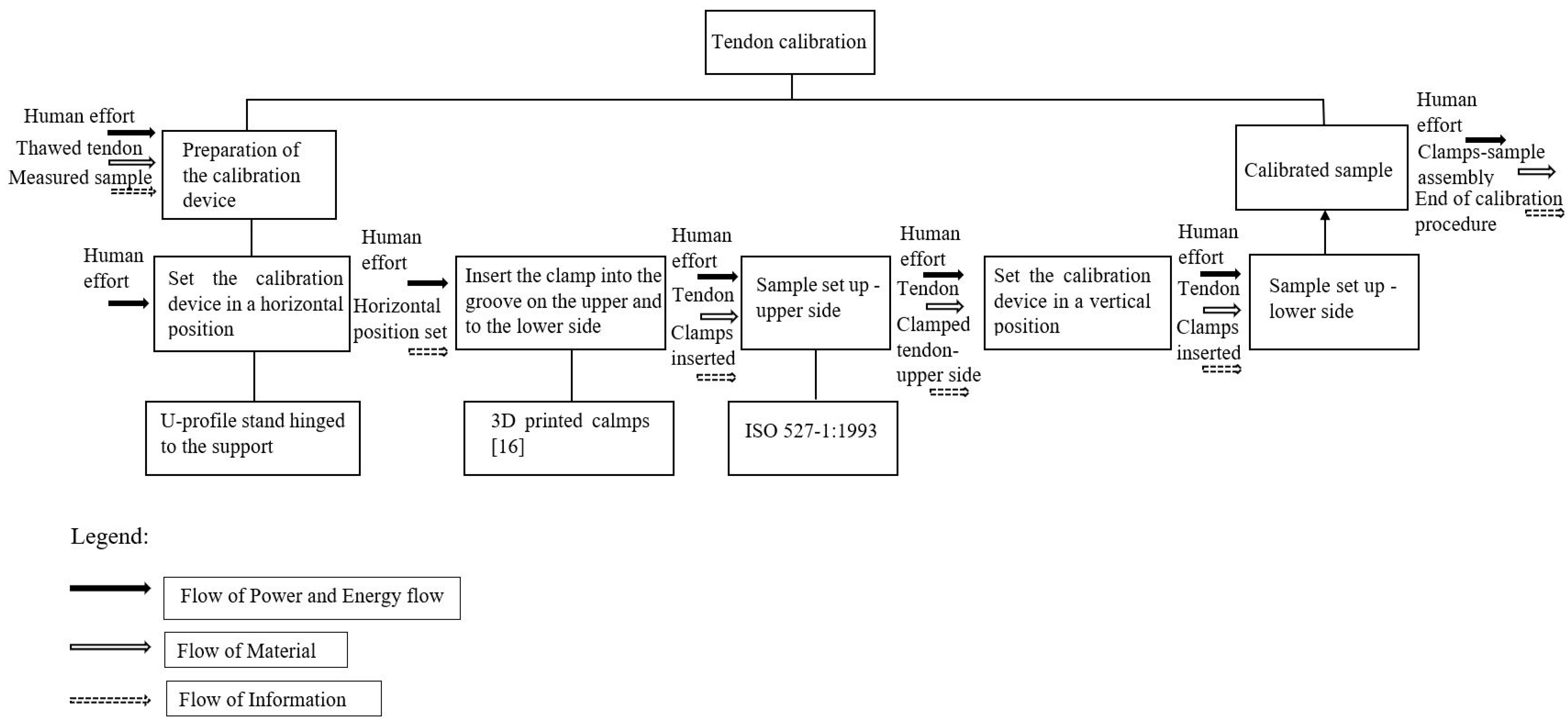
To develop a functional structure, it is necessary to extract the rough structure of a small number of sub-functions from the list of requirements, and then more complex sub-functions are classified step by step. It is important to describe the main flow of the functional structure that is relevant to structural elaboration. The functional structure must be as simple as possible because it is the prerequisite for obtaining a simple and cheap product. The functional structure of the tendon calibration device has a main flow that contains the basic functions that must be performed to ultimately obtain a sample suitable for the rolling experiment. These functions include the energy flow represented by the human labour invested, the material, which in this case is a tendon, and the basic information transferred from step to step. The prepared test sample represents the end of the functional structure (Figure 3).
2.2. Design of the Calibrator
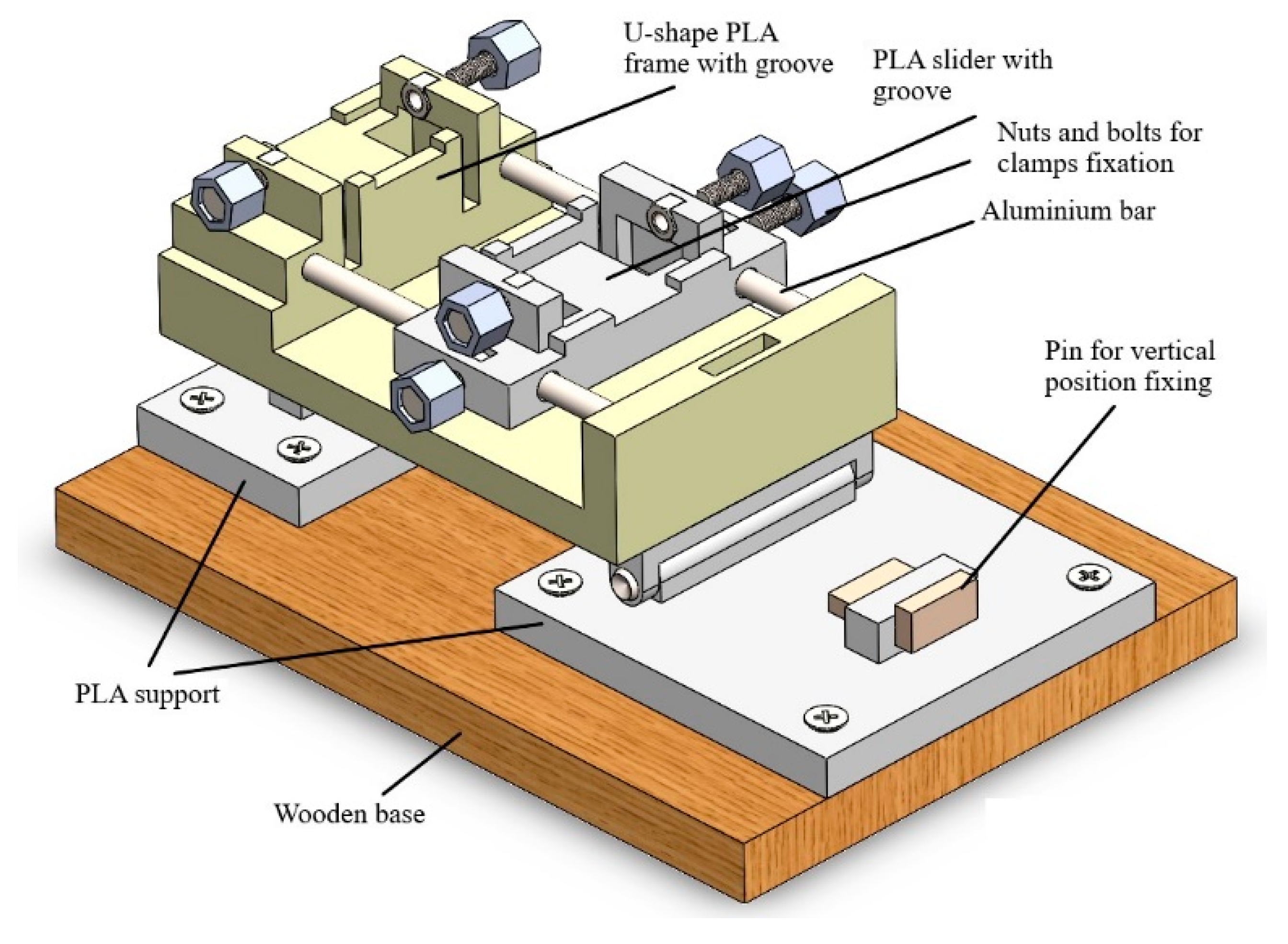
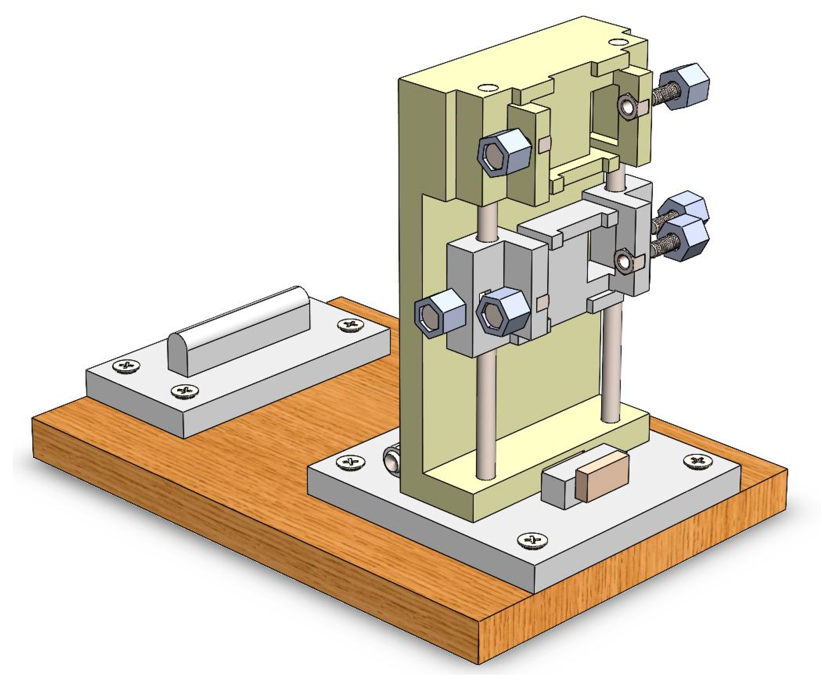
The SolidWorks Professional 2020 Educational License (Dassault Systemes, Stuttgart, Germany) software was used for the product design. All models were extracted in the STL file. Ultimaker Cura free software was used for the STL file processing prior to 3D printing using the hobby-grade FDM 3D Printer Creality Ender-3 Pro (Shenzhen Creality 3D Technology Co., Ltd., Shenzen, China). Figure 4 presents the final assembly of the calibrator in a horizontal position, and Figure 5 shows the assembly in a vertical position.
2.3. Specimen Preparation
The samples used in this study belong to the archive collection of materials stored at the Department of the Anatomy and Neuroscience of the Faculty of Medicine at Josip Juraj Strossmayer University in Osijek, Croatia. The tendons were dissected from the cadavers (10 males with the age of 72 ± 4, and 6 females with the age of 67 ± 4) without any knee joint collagenosis and knee injuries. The distal tendons of 8 m.gracilis and the upper third of 8 m.quadriceps femoris were used for the analysis and, until the day of the tests, kept frozen at −80 °C. Before the analysis, the tendons were placed in Ringer’s solution at room temperature to thaw. The length of the tendons was measured, followed by the determination of the cross-sectional area (CSA). Several methods have been proposed dealing with the determination of the CSA, such as [29,30,31,32]. Therefore, as fast specimen preparation has to be fulfilled to reduce tissue dehydration as much as possible, the method presented in [29] was chosen to be applied in this study since it is reported as simple, rapid, and non-destructive method. Therefore, an alginate dental impression material (THIXOTROPIC ALGINATE, Polident, Volčja Draga, Slovenia) was used to make a mould of the specimens to be measured. The alginate powder was mixed with cold water with a mixing ratio of 9 g powder/19 mL water. The mixing time was approximately 30 s immediately, followed by a working time that lasted approximately 80 s. This is according to the manufacturer’s instructions. To test the method, a quick pre-test was conducted using a pen (Figure 8). A custom-made, 3D-printed mould was designed, after which a layer of paste was put into the mould, placed horizontally, and the pen was laid. An additional amount of the paste was added to fill the mould. The process advanced very fast, and the CSA of the pen could be determined and evaluated. Hence, the same process was applied for the tendons (Figure 9). The ImageJ free available software for image processing and analysis was used to measure CSA. The CSA of each specimen was measured 5 times, and the mean value was used. The next step was a quick visual inspection using a microscope camera (0.3 m CMOS, 2 MP, 1000 × optical zoom), eventually to detect dissection errors (scalpel incisions). This could lead to premature rupture of the tendon and thus unusable results.
Finally, the length of the specimen was measured, and the ISO 527-1:1993 standard was utilised. Table 2 shows the dimensions of the measured tendons.
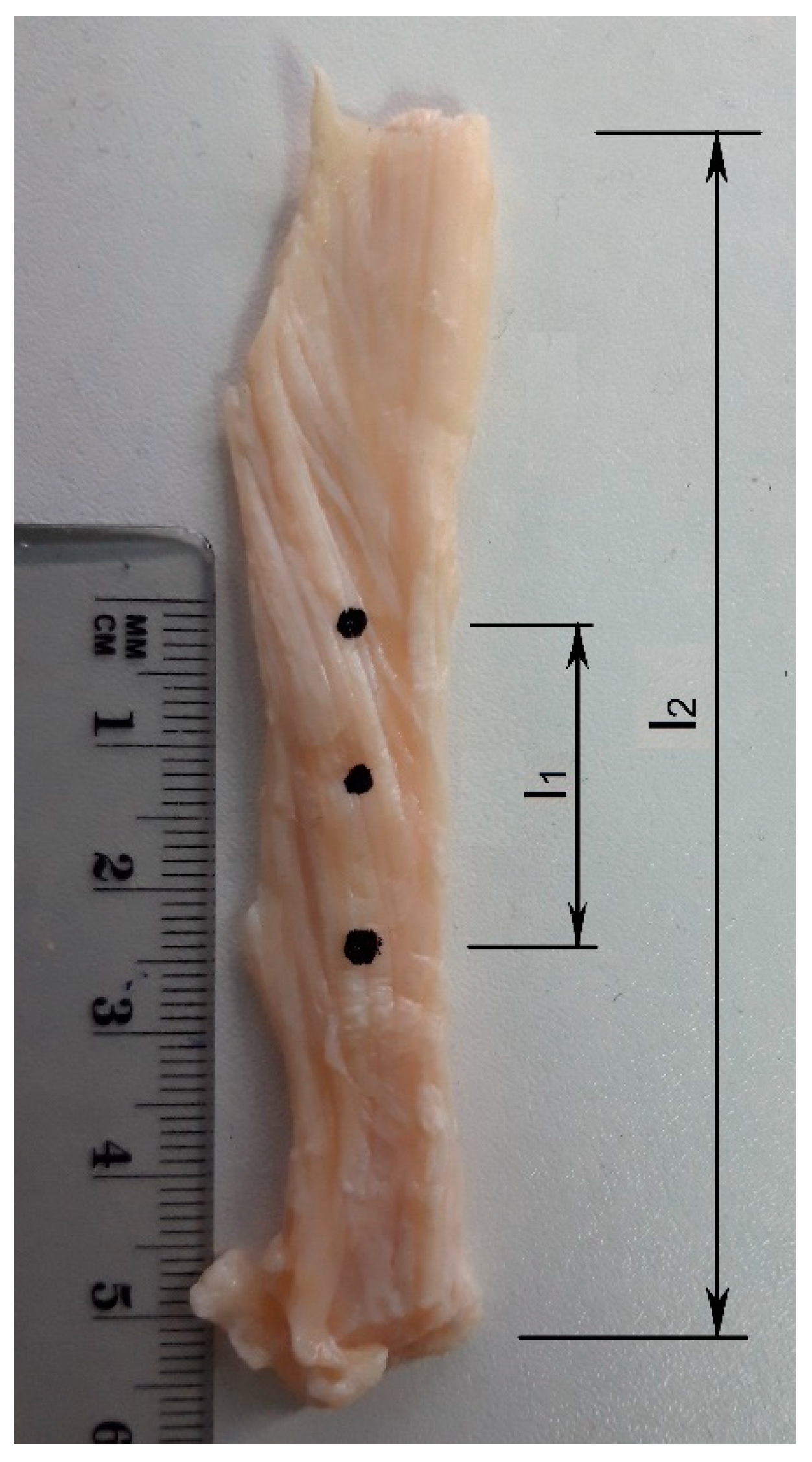
2.4. Utilisation of ISO 527-1:1993
When considering the viscoelastic properties of tendons and tendon preparation diversities throughout the literature, this paper presents the calibration procedure based on the ISO 527-1:1993 standard (Figure 10). The 5A and 5B types of the specimen were used in the following way: If the measured tendon length was ≥75 mm, the gauge length would be determined according to the specifications of the 5A type of the specimen, analogously; if the measured tendon length was ≥35 mm and <75 mm, the gauge length would be determined according to the 5B type of the specimen. Tendons remained in their natural shape without any geometry changes. Figure 11 presents the marked specimen prepared for calibration for the uniaxial tensile test. It was prepared according to type 5A. Dimensions can be seen in Table 3.
2.5. Functionality Test
According to Figure 3, functionality was tested and explained as follows:
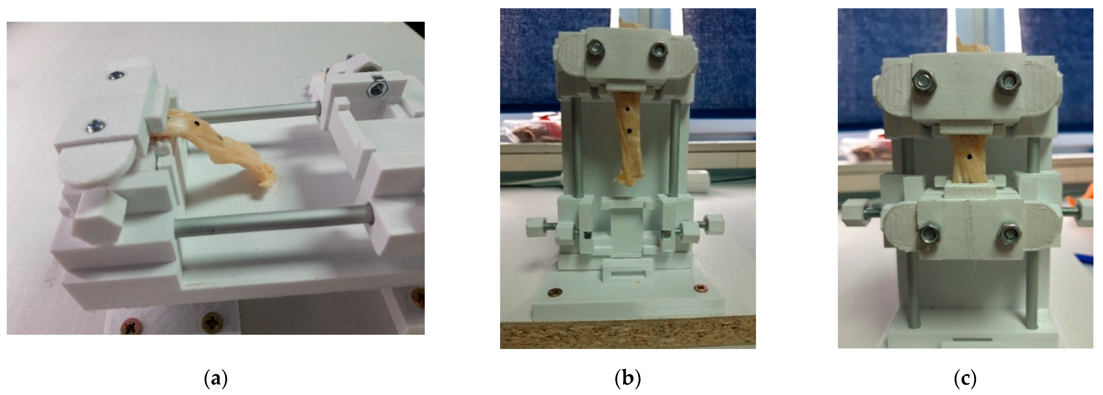
After preparing the specimen according to Figure 11, the calibration device was placed in a horizontal position. The lower part of the clamp was placed in the groove on the upper part and fixed with screws so that it would not fall out of the groove. The upper part of the tendon was placed on the clamp and lined up considering the position of the marker. The upper part of the clamp was put on and fixed with screws (Figure 12a). The device was then placed in a vertical position so that the free end of the specimen relaxes downwards (Figure 12b). The slider with the groove was positioned at a distance of l1 from the upper part and fixed to aluminium rods with screws. The lower part of the clamp was placed in the groove of the slider and fixed with screws so that it could not fall out. The upper part of the clamp was placed and tightened with the tendon in between. After the screws holding the clamps in the grooves were loosened, the tendon–clamps assembly was ready for the tensile test (Figure 12c). This completed the calibration process and the functionality test. For the clamps’ design, see [22].
3. Results and Discussion
A total of 16 human tendons were selected for the uniaxial tensile test and subjected to the calibration procedure. Due to the requirements of the MPFL reconstruction procedure, tendons were examined in their natural shape and therefore not subjected to the shaping of the specimen into the standard dog-bone shape. The aim was to determine the biomechanical properties of tendons as structural elements that could replace the role of the MPFL mechanism in the human knee. To avoid arbitrariness in the preparation of the specimen by using different ratios such as the 4.25:1 or 10:1 already mentioned, the standard ISO 527-1:1993 was used, similar to [20,21], but in this case, for the specimen in its natural form. Compared with [20,21], with this calibrator, it is possible to prepare the test body in both horizontal and vertical positions. The emphasis was on the vertical position, as it allowed the collagen fibres to align and relax downwards. If this condition is not met, the tensile load will not be evenly distributed in the sample and the tendon may break prematurely, producing false results. In addition, the ability to move the slider on the aluminium rods means that any value of gauge length in the range 0–60 mm can be achieved if required, unlike [20,21] where the gauge length can be achieved in steps. Another advantage over the studies conducted is its short preparation time of 3 min compared with 20–30 min. According to the total tendon lengths (l2), all tendons were calibrated considering the 5A type of the specimen, where the dimension l1 was 25 ± 1 mm and represented the gauge length. The calibration process was completed within 3 min per tendon. In case of large specimen size, it is recommended to store the prepared samples in Ringer´s solution [33]. This will help in tissue dehydration prevention. If possible, heating the solution to the human body temperature, preferably to 33 °C, which is classified as the temperature in the human knee [18], would be desirable. One more benefit in that period of waiting is that the tendon tissue can relax from any induced stress during the calibration procedure. Furthermore, in this study, it was easy to manipulate the calibrator between horizontal and vertical positions. While considering the work available in the literature in which the shape of the cross-sectional area of the tendon was assumed to be rectangular or an elliptic, it is shown in this study, by using the method described in [29], that the shape and CSA can be determined very fast and precisely. The occurrence of air bubbles, which can affect the CSA value and thus affect the cross-sectional shape, proved to be a disadvantage if the bubble was held at the edge of the tendon but this could be reduced with a better mixing procedure.
In order to avoid a long time of sample preparation within the working area of the tensile testing machine, which is due to the peculiarities of materials such as tendons, the sample can be prepared in advance with this calibration device without entering the working area of the tensile testing machine such as Shimadzu AGS-X 10 kN. The gauge length was set in advance so that the prepared specimen only had to be inserted into the machine’s jaws and tested with the parameters already set. Furthermore, in addition to calibration according to the gauge length of 25 ± 1 mm, this calibration device also offered the maximum gauge length of 60 mm, with a maximum tendon length of 120 mm. Even though the calibration process was completed within 3 min per tendon, it was important to keep the tendons wet by spraying them. As an overall result, all requirements, desired measures, and information from the list of requirements were fulfilled. All tendons were successfully calibrated and prepared for the next step—the uniaxial tensile test. The detailed statistical analysis of human gracilis and quadriceps tendons prepared with this calibration device can be found in [24]. All data were processed using Statistica 12.0 software for descriptive statistical analysis. The tendons were divided into two independent groups. Student’s t-test was used for their correlation. The results show statistically significant differences in maximum force, extension, tensile strength, elongation, and modulus of elasticity. Only for stiffness, there were no statistical differences between the two groups of tendons. In summary, the quadriceps tendons exhibit superior biomechanical properties than the gracilis tendons. Table 4 shows the biomechanical properties of the tendons in detail.
The correlation with reported studies related to the tensile tests of the gracilis and quadriceps tendons is given below in Table 5. It was found that the achieved data using this calibration device with the proposed standard ISO 527-1:1993 fall among results in the reported studies, and there are no extreme differences between values.
4. Conclusions
This work contributes to the improvement of current protocols for tissue testing and shows how to reduce the arbitrariness observed in the literature. The proposed calibration device and procedure using the standard ISO 527-1:1993 could be useful in future standardisation procedures in tissue testing.
The main contributions of this study are as follows:
- Functional device for tendons calibration and preparation for the tensile tests;
- Utilisation of ISO 527-1:1993 standard to test tendons in their natural shape;
- Preparation in horizontal and vertical positions.
- Future research will seek to improve the calibrator in terms of the following features:
- Immersing the tendon in liquid during calibration to avoid dehydration of the tissue and spraying procedures;
- Heating the liquid to a temperature of 33 °C for the tensile test procedure to warm the tendon tissue as much as possible in advance;
- Improving the design to be less robust.
Author Contributions
Conceptualisation, I.G.; methodology, I.G.; validation, I.G.; formal analysis, I.G.; investigation, I.G.; resources, I.G.; data curation, I.G.; writing—original draft preparation, I.G.; writing—review and editing, M.K.; supervision and review, Ž.I.; supervision and review. T.J.L. All authors have read and agreed to the published version of the manuscript.
Funding
This research received no external funding.
Institutional Review Board Statement
This study was conducted according to the guidelines of the Declaration of Helsinki and approved by the Ethics Committee of the Josip Juraj Strossmayer University of Osijek (Number: 2158-61-07-19-17, date of approval 30 April 2019).
Informed Consent Statement
Not applicable.
Data Availability Statement
Not applicable.
Conflicts of Interest
The authors declare no conflict of interest.
References
- Özkaya, N.; Nordin, M.; Goldsheyder, D.; Leger, D. Fundamentals of Biomechanics: Equilibrium, Motion and Deformation; Springer: Berlin/Heidelberg, Germany, 2012. [Google Scholar] [CrossRef] [Green Version]
- Anonymous. Anisotropic Materials. In Analytical Methods in Anisotropic Elasticity; Birkhäuser: Boston, MA, USA, 2005. [Google Scholar] [CrossRef]
- Chanda, A.; Callaway, C. Tissue Anisotropy Modeling Using Soft Composite Materials. Appl. Bionics Biomech. 2018, 2018, 4838157. [Google Scholar] [CrossRef] [Green Version]
- Thorpe, C.T.; Screen, H.R.C. Tendon Structure and Composition. In Metabolic Influences on Risk for Tendon Disorders; Ackermann, P., Hart, D., Eds.; Springer: Cham, Switzerland, 2016; Volume 920. [Google Scholar] [CrossRef]
- Nikolić, V.; Hudec, M.B. Principi Biomehnaike; Ljevak: Zagreb, Croatia, 2011; Available online: https://www.bib.irb.hr/611801 (accessed on 20 November 2021).
- Wan Abas, W.A. Biaxial tension test of human skin in vivo. Biomed. Mater. Eng. 1994, 4, 473–486. [Google Scholar]
- Morgan, E.F.; Unnikrisnan, G.U.; Hussein, A.I. Bone Mechanical Properties in Healthy and Diseased States. Annu. Rev. Biomed. Eng. 2018, 20, 119–143. [Google Scholar] [CrossRef]
- Smeets, K.; Bellemans, J.; Scheys, L.; Eijnde, B.O.; Slane, J.; Claes, S. Mechanical Analysis of Extra-Articular Knee Ligaments. Part two: Tendon grafts used for knee ligament reconstruction. Knee 2017, 24, 957–964. [Google Scholar] [CrossRef]
- Criscenti, G.; De Maria, C.; Sebastiani, E.; Tei, M.; Placella, G.; Speziali, A.; Vozzi, G.; Cerulli, G. Material and structural tensile properties of the human medial patello-femoral ligament. J. Mech. Behav. Biomed. Mater. 2016, 54, 141–148. [Google Scholar] [CrossRef]
- Criscenti, G.; De Maria, C.; Sebastiani, E.; Tei, M.; Placella, G.; Speziali, A.; Vozzi, G.; Cerulli, G. Quasi-linear viscoelastic properties of the human medial patello-femoral ligament. J. Biomech. 2015, 48, 4297–4302. [Google Scholar] [CrossRef]
- Woo, L.-Y.; Orlando, C.A.; Gomez, M.A.; Frank, C.B.; Akeson, W.H. Tensile properties of the medial collateral ligament as a function of age. J. Orthop. Res. 1986, 4, 133–141. [Google Scholar] [CrossRef]
- Abramowitch, S.D.; Zhang, X.; Curran, M.; Kilger, R. A comparison of the quasi-static mechanical and non-linear viscoelastic properties of the human semitendinosus and gracilis tendons. Clin. Biomech. 2010, 25, 325–331. [Google Scholar] [CrossRef] [Green Version]
- Mlyniec, A.; Dabrowska, S.; Heljak, M.; Weglarz, E.P.; Wojcik, K.; Ekiert-Radecka, M.; Obuchowicz, R.; Swieszkowski, M. The dispersion of viscoelastic properties of fascicle bundles within the tendon results from the presence of interfascicular matrix and flow of body fluids. Mater. Sci. Eng. C 2021, 130, 112435. [Google Scholar] [CrossRef]
- Duenwald, S.E.; Vanderby, R.; Lakes, R.S. Viscoelastic Relaxation and Recovery of Tendon. Ann. Biomed. Eng. 2009, 37, 1131–1140. [Google Scholar] [CrossRef]
- Hayes, A.; Easton, K.; Devanaboyina, P.T.; Wu, J.-P.; Kirk, T.B.; Lloyd, D. A review of methods to measure tendon dimensions. J. Orthop. Surg. Res. 2019, 14, 18. [Google Scholar] [CrossRef]
- Woo, S.L.-Y.; Akeson, W.H.; Jemmott, G.F. Measurements of nonhomogeneous, directional mechanical properties of articular cartilage in tension. J. Biomech. 1976, 9, 785–791. [Google Scholar] [CrossRef]
- Lionello, G.; Sirieix, C.; Baleani, M. An effective procedure to create a speckle pattern on biological soft tissue for digital image correlation measurements. J. Mech. Behav. Biomed. Mater. 2014, 39, 1–8. [Google Scholar] [CrossRef] [PubMed]
- Graf, B.K.; Vanderby, R., Jr.; Ulm, M.J.; Rogalski, R.P.; Thielke, R.J. Effect of preconditioning on the viscoelastic response of primate patellar tendon. Arthrosc.: J. Arthrosc. Relat. Surgery. 1994, 10, 90–96. [Google Scholar] [CrossRef]
- Duenwald, S.E.; Vanderby, R., Jr.; Lakes, R.S. Stress relaxation and recovery in tendon and ligament: Experiment and modeling. Biorheology 2010, 47, 1–14. [Google Scholar] [CrossRef]
- Scholze, M.; Singh, A.; Lozano, P.F.; Ondruschka, B.; Ramezani, M.; Werner, M.; Hammer, N. Utilization of 3D printing technology to facilitate and standardize soft tissue testing. Sci. Rep. 2018, 8, 11340. [Google Scholar] [CrossRef] [PubMed] [Green Version]
- Scholze, M.; Safavi, S.; Li, K.C.; Ondruschka, B.; Werner, M.; Zwirner, J.; Hammer, N. Standardized tensile testing of soft tissue using a 3D printed clamping system. HardwareX 2020, 8, e00159. [Google Scholar] [CrossRef]
- Grgić, I.; Wertheimer, V.; Karakašić, M.; Ivandić, Ž. 3D Printed Clamps for In Vitro Tensile Tests of Human Gracilis and the Superficial Third of Quadriceps Tendons. Appl. Sci. 2021, 11, 2563. [Google Scholar] [CrossRef]
- Grgić, I.; Wertheimer, V.; Karakašić, M.; Ivandić, Ž. Development of a 3D Printed Double-Acting Linear Pneumatic Actuator for the Tendon Gripping. Polymers 2021, 13, 2528. [Google Scholar] [CrossRef] [PubMed]
- Wertheimer, V.; Grgić, I.; Zelić, Z.; Ivandić, Ž.; Koprivčić, I.; Zelenić, M.; Karakašić, M. Biomechanical Analysis of the Gracilis and Superficial Third of the Quadriceps Tendons Concerning MPFL Biomechanics. Tech. Gaz. 2021, 28, 1575–1581. [Google Scholar] [CrossRef]
- Husain, K.N.; Stojković, M.; Vitković, N.; Milovanović, J.; Trajanović, M.; Rashid, M.; Milovanović, A. Procedure for Creating Personalized Geometrical Models of the Human Mandible and Corresponding Implants. Tech. Gaz. 2019, 26, 1044–1051. [Google Scholar] [CrossRef]
- Alghrairi, M.K.; Sulaiman, N.B.; Sidek, R.B.M.; Mutashar, S. Simple and Efficient Transcutaneous Inductive Micro-System Device Based on ASK Modulation at 6.78 MHz ISM Band. Tech. Gaz. 2020, 27, 1478–1485. [Google Scholar] [CrossRef]
- Zuccon, G.; Bottin, M.; Ceccarelli, M.; Rosati, G. Design and Performance of an Elbow Assisting Mechanism. Machines 2020, 8, 68. [Google Scholar] [CrossRef]
- Russo, M.; Ceccarelli, M. Analysis of a Wearable Robotic System for Ankle Rehabilitation. Machines 2020, 8, 48. [Google Scholar] [CrossRef]
- Goodship, A.E.; Birch, H.L. Cross sectional area measurement of tendon and ligament in vitro: A simple, rapid, non-destructive technique. J. Biomech. 2005, 38, 605–608. [Google Scholar] [CrossRef]
- Race, A.; Amis, A.A. Cross-sectional area measurement of soft tissue. A new casting method. J. Biomech. 1996, 29, 1207–1212. [Google Scholar] [CrossRef]
- Smith, R.K.; Jones, R.; Webbon, P.M. The cross-sectional areas of normal equine digital flexor tendons determined ultrasonographically. Equine Vet. J. 1994, 26, 460–465. [Google Scholar] [CrossRef] [PubMed]
- Ge, X.-J.; Zhang, L.; Xiang, G.; Hu, Y.-C.; Lun, D.-X. Cross-Sectional Area Measurement Techniques of Soft Tissue: A Literature Review. Orthop. Surg. 2020, 12, 1547–1566. [Google Scholar] [CrossRef] [PubMed]
- Hongpaisan, J.; Roomans, G.M. Retaining ionic concentrations during in vitro storage of tissue for microanalytical studies. J. Microsc. 1999, 193, 257–267. [Google Scholar] [CrossRef] [Green Version]
- Noyes, F.R.; Butler, D.L.; Grood, E.S.; Zernicke, R.F.; Hefzy, M.S. Biomechanical analysis of human ligament grafts used in knee ligament repairs and reconstructions. J. Bone Jt. Surg. 1984, 66, 344–352. [Google Scholar] [CrossRef]
- Handl, M.; Drzik, M.; Cerulli, G.; Povysil, C.; Chlpik, J.; Varga, F. Reconstruction of the anterior cruciate ligament: Dynamic strain evaluation of the graft. Knee Surg. Sports Traumatol. Arthrosc. 2007, 15, 233–241. [Google Scholar] [CrossRef] [PubMed]
- Butler, D.L.; Grood, E.S.; Noyes, F.R.; Zernicke, R.F.; Brackett, K. Effects of structure and strain measurement technique on the material properties of young human tendons and fascia. J. Biomech. 1984, 17, 579–596. [Google Scholar] [CrossRef]
- Mabe, I.; Hunter, S. Quadriceps tendon allografts as an alternative to Achilles tendon allografts: A biomechanical comparison. Cell Tissue Bank 2014, 15, 523–529. [Google Scholar] [CrossRef]
- Staubli, H.U.; Schatzmann, L.; Brunner, P.; Rincon, L.; Nolte, L.-P. Mechanical Tensile Properties of the Quadriceps Tendon and Patellar Ligament in Young Adults. Am. J. Sports Med. 1999, 27, 27–34. [Google Scholar] [CrossRef] [PubMed]
- Shani, R.; Umpierez, E.; Nasert, M.; Hiza, E.; Xerogeanes, J. Biomechanical Comparison of Quadriceps and Patellar Tendon Grafts in Anterior Cruciate Ligament Reconstruction. J. Arthrosc. Relat. Surg. 2015, 32, 1–5. [Google Scholar] [CrossRef] [PubMed]
Figure 1.
Diversity of results [8] (reprinted from K. Smeets, J. Bellemans, L. Scheys, B. O. Eijnde, J. Slane, S. Claes (2017)).
Figure 1.
Diversity of results [8] (reprinted from K. Smeets, J. Bellemans, L. Scheys, B. O. Eijnde, J. Slane, S. Claes (2017)).

Figure 2.
The black box of the functional structure.

Figure 3.
The functional structure of the calibrator.

Figure 4.
The horizontal position of the calibration device.

Figure 5.
The vertical position of the calibration device.

Figure 6.
Physical model of the calibrator.

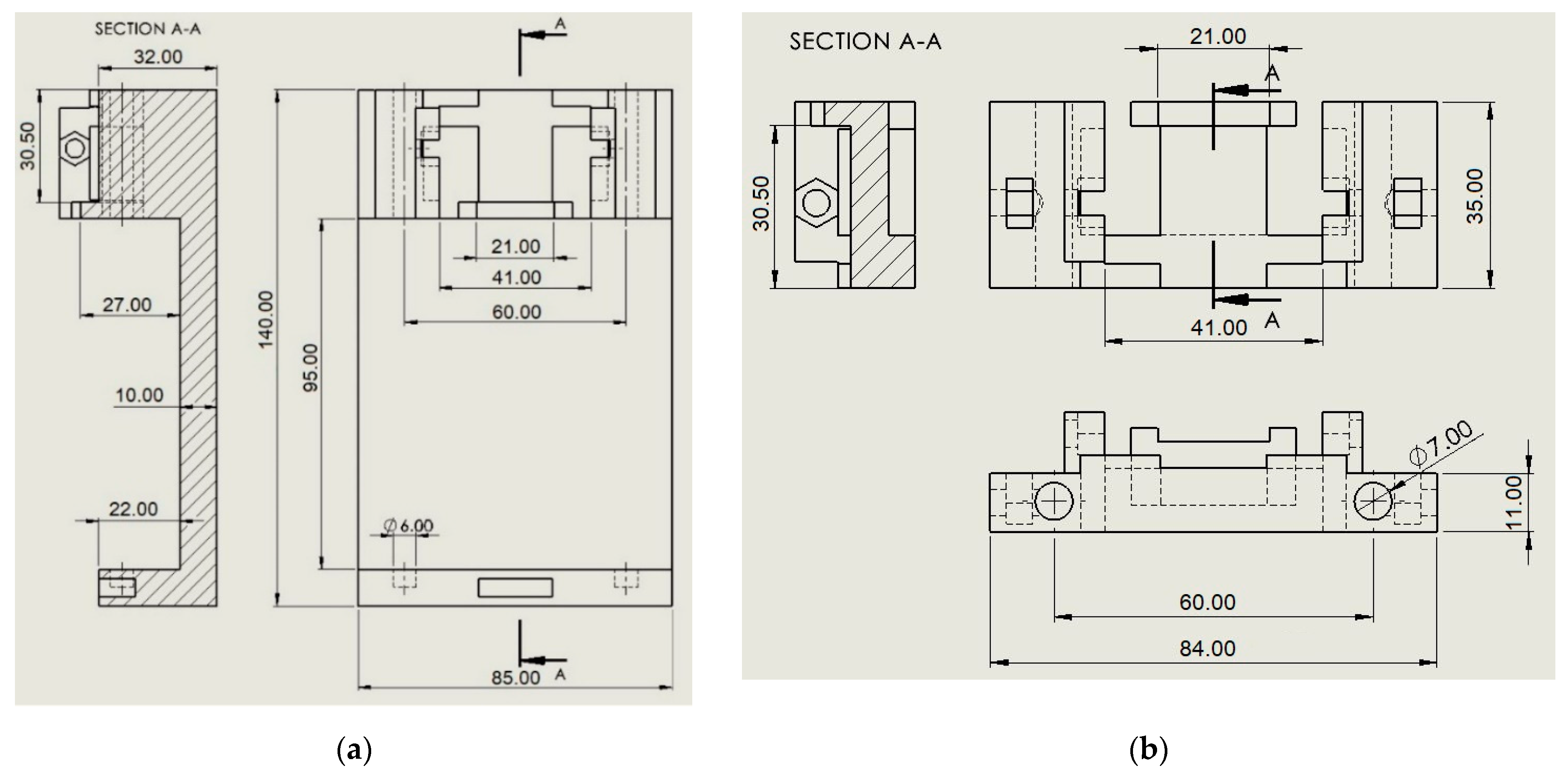
Figure 7.
Dimensions of main parts: (a) U-shape profile with integrated groove; (b) the slider with groove.
Figure 7.
Dimensions of main parts: (a) U-shape profile with integrated groove; (b) the slider with groove.

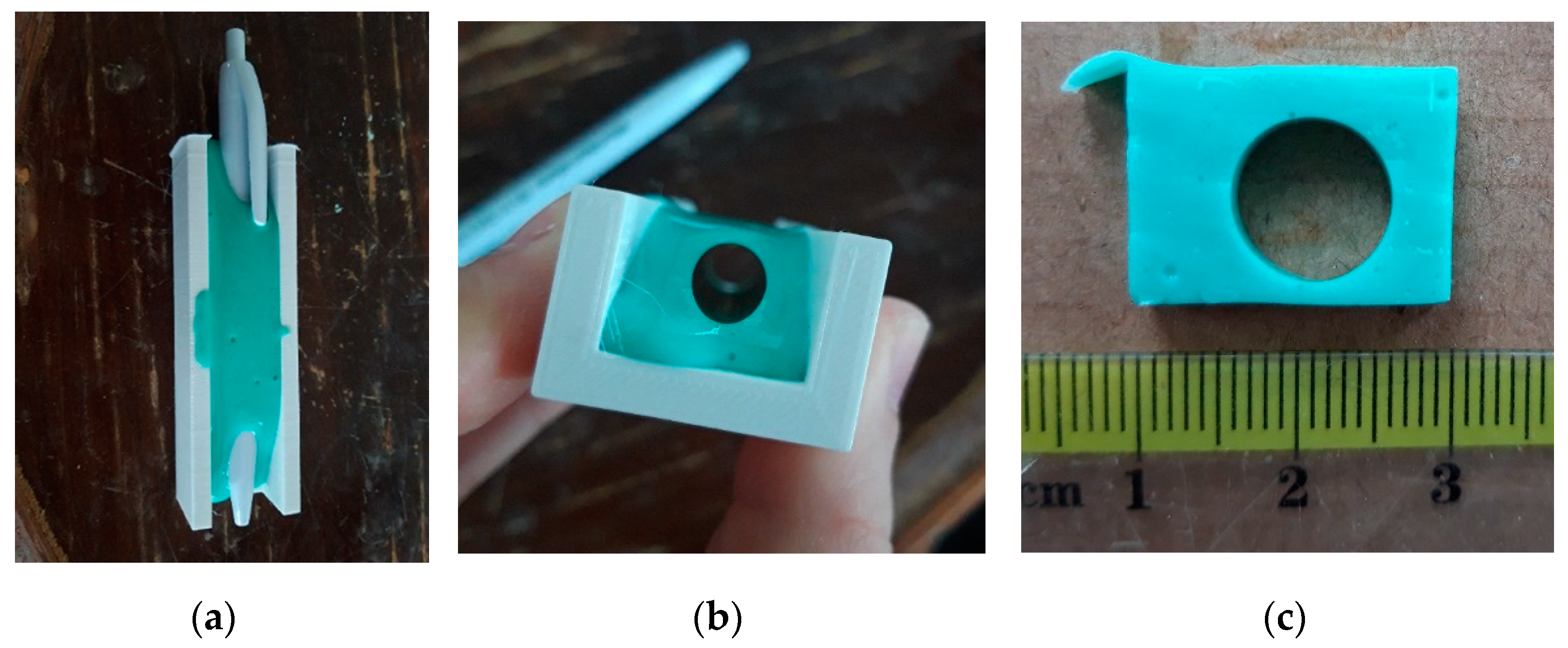
Figure 8.
Pre-test. CSA of a pen: (a) pen in the mould filled with an alginate paste; (b) the CSA of the pen; (c) a transverse section with the ruler for the image calibration.
Figure 8.
Pre-test. CSA of a pen: (a) pen in the mould filled with an alginate paste; (b) the CSA of the pen; (c) a transverse section with the ruler for the image calibration.

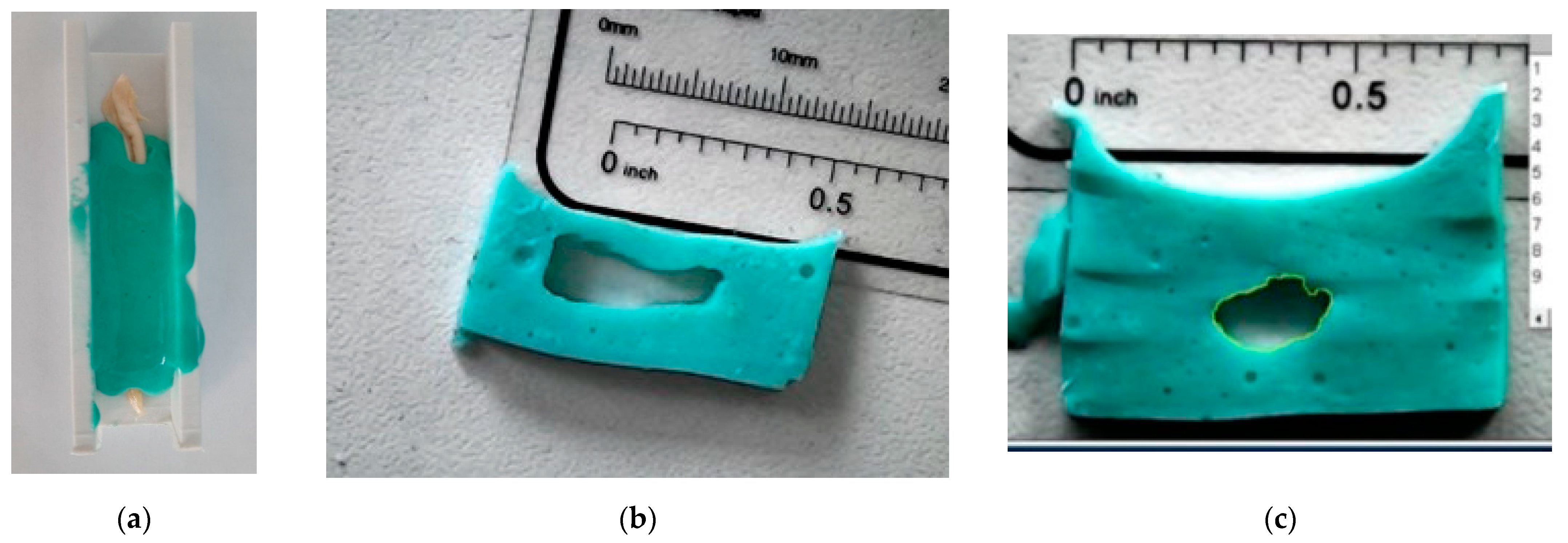
Figure 9.
Tendon’s CSA measurement: (a) specimen in the mold filled with an alginate paste; (b) the CSA and the shape of the quadriceps tendon; (c) the CSA and shape of the gracilis tendon with image analysis and measurement.
Figure 9.
Tendon’s CSA measurement: (a) specimen in the mold filled with an alginate paste; (b) the CSA and the shape of the quadriceps tendon; (c) the CSA and shape of the gracilis tendon with image analysis and measurement.

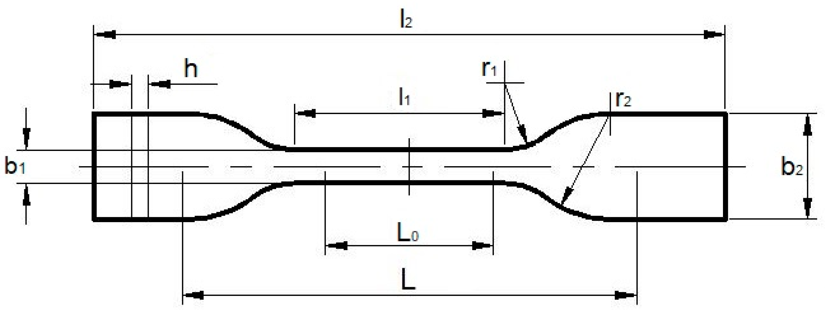
Figure 10.
The shape of the specimen according to ISO 527:1-1993.

Figure 11.
The marked specimen according to ISO 527-1:1993.

Figure 12.
The specimen preparation using calibration device: (a) specimen in the upper clamps in the horizontal position; (b) vertical position of the calibrator with the specimen relaxing downwards; (c) the specimen–clamps assembly in the calibrator.
Figure 12.
The specimen preparation using calibration device: (a) specimen in the upper clamps in the horizontal position; (b) vertical position of the calibrator with the specimen relaxing downwards; (c) the specimen–clamps assembly in the calibrator.


Table 1.
FDM parameters.
| Parameters | Value |
|---|---|
| Layer height | 0.01 mm |
| Shell thickness | 0.4 mm |
| Overlap percentage | 40% |
| Infill density | 100% |
| Printing temperature | 200 °C |
| Infill speed | 20 mm/s |
| Wall speed | 10 mm/s |
| Build plate temperature | 70 °C |
Table 2.
The dimensions of the tendons.
| Mean (SD) | ||
|---|---|---|
| Gracilis | Quadriceps | |
| CSA, mm2 | 10.65 (1.4) | 19.36 (3.2) |
| Length, mm | 90.12 (7.6) | 85.97 (4.1) |
| Width, mm | 5 (0.5) | 9.91 (0.8) |
| Thickness, mm | 2.73 (0.4) | 2.46 (0.3) |
Table 3.
ISO 527-1:1993 specimen dimensions.
| Sample Type | Dimensions, mm | |
|---|---|---|
| 5A | 5B | |
| l2 | ≥75 | ≥35 |
| b2 | 12.5 ± 1 | 6 ± 0.5 |
| l1 | 25 ± 1 | 12 ± 0.5 |
| b1 | 4 ± 0.1 | 2 ± 0.1 |
| r1 | 8 ± 0.5 | 3 ± 0.1 |
| r2 | 12.5 ± 1 | 3 ± 0.1 |
| L | 50 ± 2 | 20 ± 2 |
| L0 | 20 ± 0.5 | 10 ± 0.2 |
| h | ≥2 | ≥1 |
Table 4.
Biomechanical properties of human gracilis and quadriceps tendons [24] (reprinted from Wertheimer, V.; Grgić, I.; Zelić, Z.; Ivandić, Ž.; Koprivčić, I.; Zelenić, M.; Karakašić, M. (2021)).
Table 4.
Biomechanical properties of human gracilis and quadriceps tendons [24] (reprinted from Wertheimer, V.; Grgić, I.; Zelić, Z.; Ivandić, Ž.; Koprivčić, I.; Zelenić, M.; Karakašić, M. (2021)).
| Mean (SD) | 95% CI | |||||
|---|---|---|---|---|---|---|
| Gracilis | Quadriceps | Divergence | From | to | p-Value (Student t-Test) | |
| Maximum force, N | 563.9 (119.6) | 788.3 (155.3) | −224.3 | −373 | −75.7 | 0.006 |
| Extension, mm | 2.45 (0.25) | 2.9 (0.4) | −0.43 | −0.77 | −0.11 | 0.01 |
| Tensile strength, MPa | 55.9 (20.5) | 36 (4.6) | 19.9 | 2.68 | 37.2 | 0.03 |
| Elongation, % | 12.2 (1.2) | 14.4 (1.8) | −2.2 | −3.83 | −0.54 | 0.01 |
| Stiffness, N/mm | 66.6 (23.0) | 78.4 (17.5) | −11.9 | −33.8 | 10.1 | 0.27 |
| Elastic modulus, MPa | 559.9 (226.6) | 303.2 (35.1) | 252.8 | 62.8 | 442.8 | 0.008 |
Table 5.
Comparison of available data from other studies with this study [24] (reprinted from Wertheimer, V.; Grgić, I.; Zelić, Z.; Ivandić, Ž.; Koprivčić, I.; Zelenić, M.; Karakašić, M. (2021)).
Table 5.
Comparison of available data from other studies with this study [24] (reprinted from Wertheimer, V.; Grgić, I.; Zelić, Z.; Ivandić, Ž.; Koprivčić, I.; Zelenić, M.; Karakašić, M. (2021)).
| Mean (SD) | ||||
|---|---|---|---|---|
| n | Elastic Modulus, MPa | Tensile Strength, MPa | Elongation, % | |
| GRACILIS | ||||
| Noyes et al. [34] | 11 | - | 115.5 (4) | - |
| Handl et al. [35] | 7 | - | 95.1 (13.1) | - |
| Abramowitch et al. [12] | 10 | 625.5 (148) | 63 (13.3) | 13.6 (2.1) |
| Butler et al. [36] | 11 | 612.8 (40.6) | 111.5 (4) | 26.7 (1.4) |
| Smeets et al. [8] | 11 | 1458 (476) | 155 (30.7) | 14.5 (3.1) |
| This study | 8 | 555.9 (226.6) | 55.9 (20.5) | 12.1 (1.2) |
| QUADRICEPS | ||||
| Noyes et al. [34] | 6 | - | 16.1 (1.8) | - |
| Mabe [37] | 9 | 153 (46) | 19.1 (5.42) | 16 (2) |
| Staubli et al. [38] | 8 | 462.8 (68.5) | 38 (5) | 11.2 (2.2) |
| Shani et al. [39] | 12 | 255.3 (61.4) | 23.9 (7.4) | 10.7 (1.4) |
| Smeets et al. [8] | 9 | 568 (194) | 81 (27.6) | 21.1 (6.8) |
| This study | 8 | 303.2 (35.1) | 36 (4.6) | 14.4 (1.8) |
Publisher’s Note: MDPI stays neutral with regard to jurisdictional claims in published maps and institutional affiliations. |
© 2021 by the authors. Licensee MDPI, Basel, Switzerland. This article is an open access article distributed under the terms and conditions of the Creative Commons Attribution (CC BY) license (https://creativecommons.org/licenses/by/4.0/).
Share and Cite
MDPI and ACS Style
Grgić, I.; Karakašić, M.; Ivandić, Ž.; Jurčević Lulić, T. The Development of a Gracilis and Quadriceps Tendons Calibration Device for Uniaxial Tensile Tests. Machines 2021, 9, 364. https://doi.org/10.3390/machines9120364
AMA Style
Grgić I, Karakašić M, Ivandić Ž, Jurčević Lulić T. The Development of a Gracilis and Quadriceps Tendons Calibration Device for Uniaxial Tensile Tests. Machines. 2021; 9(12):364. https://doi.org/10.3390/machines9120364
Chicago/Turabian StyleGrgić, Ivan, Mirko Karakašić, Željko Ivandić, and Tanja Jurčević Lulić. 2021. "The Development of a Gracilis and Quadriceps Tendons Calibration Device for Uniaxial Tensile Tests" Machines 9, no. 12: 364. https://doi.org/10.3390/machines9120364
Note that from the first issue of 2016, this journal uses article numbers instead of page numbers. See further details here.