ADRC-Based Robust and Resilient Control of a 5-Phase PMSM Driven Electric Vehicle
by
 , and
, and
Abir Hezzi
1, 
Seifeddine Ben Elghali
2,
Yemna Bensalem
1,
Zhibin Zhou
3,
Mohamed Benbouzid
4,5,* and
and
Mohamed Naceur Abdelkrim
1 1
MACS LR16ES22, University of Gabes, Gabes 6072, Tunisia
2
Laboratoire d’Informatique & Systèmes (UMR CNRS 7020), University of Aix-Marseille, 13397 Marseille, France
3
Institut de Recherche Dupuy de Lôme (UMR CNRS 6027), ISEN Yncréa Ouest Brest, 29200 Brest, France
4
Institut de Recherche Dupuy de Lôme (UMR CNRS 6027), University of Brest, 29238 Brest, France
5
Logistics Engineering College, Shanghai Maritime University, Shanghai 201306, China
*
Author to whom correspondence should be addressed.
Machines 2020, 8(2), 17; https://doi.org/10.3390/machines8020017
Submission received: 1 April 2020
/
Revised: 13 April 2020
/
Accepted: 14 April 2020
/
Published: 16 April 2020
Abstract
:The selection of electric machines for an Electric Vehicle (EV) is mainly based on reliability, efficiency, and robustness, which makes the 5-phase Permanent Magnet Synchronous Motor (PMSM) among the best candidates. However, control performance of any motor drive can be deeply affected by both: (1) internal disturbances caused by parametric variations and model uncertainties and (2) external disturbances related to sensor faults or unexpected speed or torque variation. To ensure stability under those conditions, an Active Disturbance Rejection Controller (ADRC) based on an online dynamic compensation of estimated internal and external disturbances, and a Linear ADRC (LADRC) are investigated in this paper. The control performance was compared with traditional controller and evaluated by considering parametric variation, unmodeled disturbances, and speed sensor fault. The achieved results clearly highlight the effectiveness and high control performance of the proposed ADRC-based strategies.
1. Introduction
Owing to its several advantages, 5-phase PMSM becomes over the years one of the best choices for the electric vehicle and other applications which require robustness and efficiency. In addition to the classical PMSM advantages such as long life, small size, simple structure, high torque to inertia ratio, easy control, etc., the high number of phases offer more robustness toward phase failures and reduces considerably the the torque ripples [1,2,3]. Nevertheless, the stability and precision of the control system is highly affected by the system non-linearity, the load torque and parametric variations and external perturbations [4]. Several strategies were introduced to improve the overall control performance by using model linearization of the multi-phase PMSM and decomposing it into virtual sub-machines mechanically coupled and magnetically decoupled. The developed control techniques can successfully stabilise the system under normal conditions but reached their limits in presence of unmodeled or unexpected disturbances. To overcome these limitations, the Active Disturbance Rejection Controller (ADRC) is investigated in this paper.
ADRC is a modern control strategy characterized by its real-time estimation and compensation for internal and external disturbances [5,6]. It is composed mainly by a Tracking Differentiator (TD), an Extended State Observer (ESO), and Non-Linear State Error Feedback (NLSEF) control law. This technique is known by its simple structure, fast response, high precision, and easy parameter setting, beside its ability to deal with disturbances and uncertainties without the needs of an accurate mathematical model of the controlled system [7,8,9]. It also proved its worth in many applications, such Servo System of Self-Propelled Gun [10], Energy Conservation Controller [11], Wind Turbine [12,13], Humanoid robot [14], and especially in the field of motor control [15,16,17].
For electric vehicle application, the ADRC technique was used in the speed control loop [18]. The objective of this approach was to cancel the impact of unknown disturbances and parameter uncertainties on cruise control by compensating nonlinear vehicle dynamics. The proposed strategy proved its ability to overcome the effect of road slope and its capacity to improve stability and tracking performance of the closed-loop system during load change. ADRC was also used to control the braking current by a real time estimation including the unmodeled perturbation of regenerative braking system of EV [19]. This technique showed a high recovery efficiency against unknown disturbance. To improve the dynamic and steady state execution of the Brushless motor used in EV, authors in [20] implemented ADRC approach to control the speed loop. This technique has an important capacity to reduce torque ripple and enhance the overall performance of the controlled system under different operation conditions.
Over and above the modeling uncertainties and unknown perturbation, a failure in electrical devices affects considerably the control performance of electric machines. A faulty mode is an irregular operating condition, where the physical parameters of the system deviate from nominal value or states [21]. There are several kinds of failures in electrical devices, among them, those related to sensors. Because of the importance of the sensors to get feedback information, it is unavoidable to find out solutions that can ensure the continuity and the stability of the motor even in presence of sensor failures. The core of the resilient control strategies proposed in literature is to find a technique able to switch between two different control strategies: one for the normal operation and the second for the faulty mode. This switching mechanism is based on the use of an observer to detect, isolate, and accommodate the sensor failures [22,23]. There are several study results dealing with the PMSM resilient control, mostly focused on an open-phase failure [24] and stator winding shorts [25] while others consider speed sensor sensor failure resilient control. Many of the proposed resilient control strategies are based on a detection and isolation mechanism [22,23,26,27,28].
This paper discusses the ADRC technique’S ability to control the 5-phase PMSM in case of speed and load torque variation while experiencing speed sensor failures. Thus, the ADRC approach is considered to be a resilient control algorithm without the need for the conventional switching mechanism or an observer, usually used to estimate the failure and the system internal state. A standard ADRC model has three main parts: TD, ESO, and NLSEF. This control approach is associated with a discretization process, which increase the nonlinear ADRC adjustment complexity. For simplification purposes, the TD module was removed and the NLSEF function was replaced by a proportional gain [29]. This modification consists of transforming the traditional form of the nonlinear ADRC to a linear one (LADRC) [12]. The LADRC mainly comprises the proportional controller and the ESO while keeping the same high performance of the nonlinear ADRC approach [30,31].
Our contribution in this paper is to investigate the efficiency of ADRC technique in controlling the 5-phase PMSM for EV as a resilient control strategy, and under different operation conditions. For this purpose, this paper is structured as follows: the Section 2 presents a general model of the EV and the 5-phase PMSM. The Section 3 introduces the mathematical model of the Active Disturbance Rejection Controller and Linear ADRC used to simplify the motor control. The Section 4 presents the speed and current control by the ADRC and LADRC, while in the Section 5, the simulation results of the 5-phase PMSM operation are presented and compared to PI regulator. The Section 6 is reserved for the conclusion.
2. Electric Vehicle Modeling
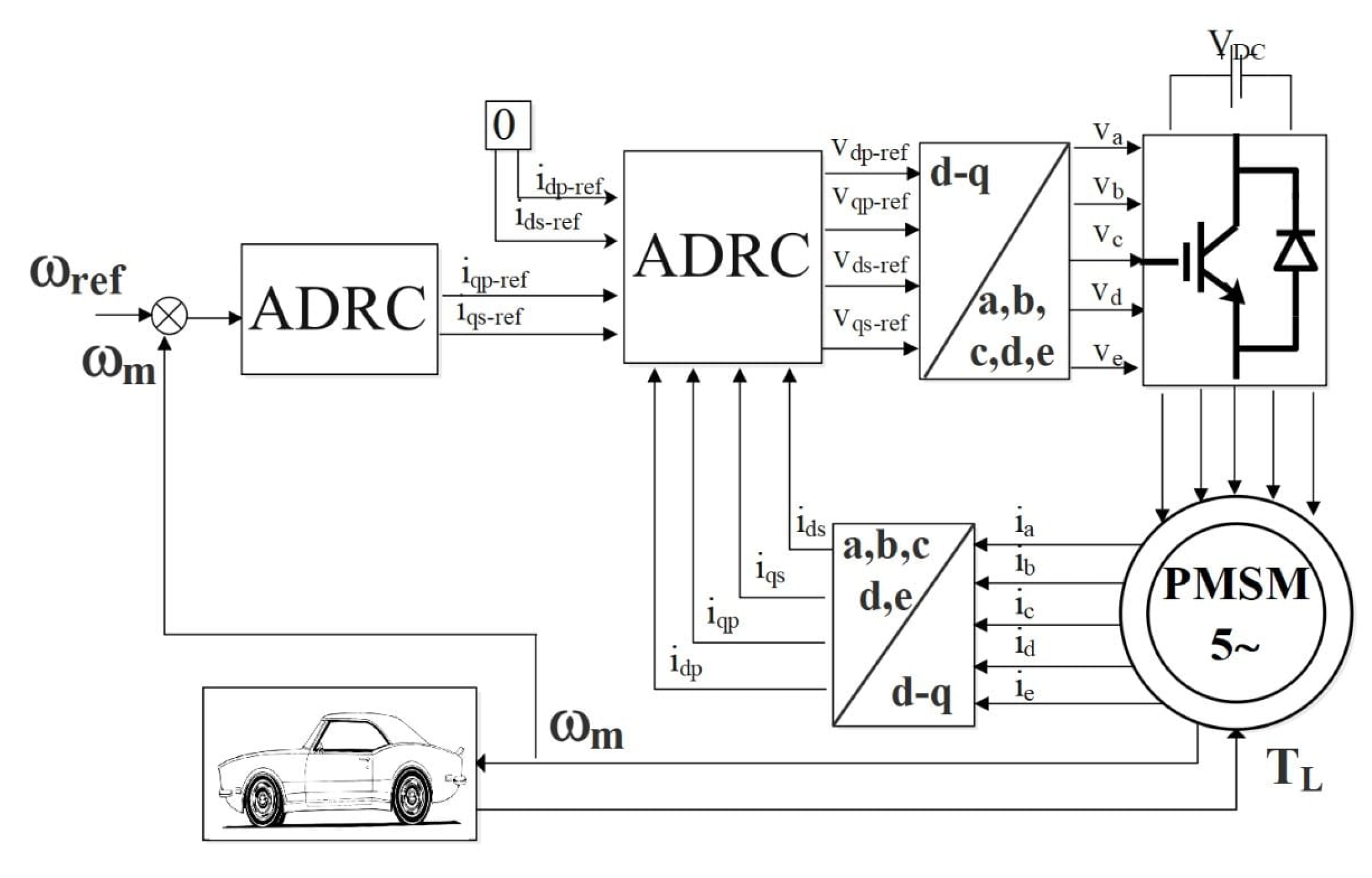
The electric vehicle model can be decomposed in four parts: the mechanical part, the electric machine part, the controller part, and finally the observer part. Figure 1 shows the EV model block diagram using two ADRC strategies.
2.1. Mechanical Part
In this study, the pitch and lateral movement of the EV are neglected and assume that the EV runs in horizontal straight line to simplify the dynamics model.
According to aerodynamics principles, then the vehicle mechanics, the road load of the EV can be expressed as follows [1]:
with
The rolling resistance force represents the friction between the road and the wheels, named also the solid friction force. This force depends usually on the type of vehicle, the road surface, the types of tires and their pressure. The acceleration force, called inertia force is the force when the vehicle accelerate or decelerate. The aerodynamic drag force called also the viscous resistance force is the force that opposes the advancement of the vehicle in the air. In a vehicle, a gear is the mechanical part which connects the wheels and the motor. The relation of speed and torque between the motor and the wheels can be described as follows:
and
Then the relation between the rotational motor speed and torque can be established by:
with is the total load torque applied to the motor.
Since the load torque is a function of the forces applied to the EV as presented in Equation (6), it can be defined as an unknown parameter changing its value during the EV operation. This undefined parameter is considered to be an external perturbation to the electric motor and directly affects the speed dynamic according to Equation (7). Therefore, it is important to define a suitable control strategy able to compensate the external variation, and keep the high performance of the electric motor over the unmodeled disturbance.
2.2. 5-Phase PMSM Modeling
To simplify the electric machine modelling, it is assumed that the 5-phases windings are regularly shifted by and the saturation of the magnetic circuits and armature reaction are neglected [1].
The mathematical model of the 5-phases PMSM in the rotating frame is described as follows [32]:
3. Active Disturbance Rejection Controller
The PMSM physical model can be affected by several internal and external perturbations, parametric variations, and potential sensor failures. Those perturbations will decrease the motor control performance. Using ADRC, as a robust and resilient control strategy, those mixed uncertainties and failures are treated as a total disturbance, which is estimated and compensated in real time. The particularity of this control technique is its ability to estimate the whole disturbance as an extended state [33,34].
3.1. Resilient Control
Fault-tolerant or resilient control strategies should allow the controlled system, the EV propulsion in our case; to be able accommodating failures while preserving stability conditions and maintaining tracking performance as close as possible to the set-point, even in presence of unknown perturbations [35]. Several studies focused on resilient control techniques that consider sensor failures producing wrong feedback signals therefore perturbing the system control. Most of the proposed resilient control approaches use two control strategies, one devoted to the healthy state while switching to another one when a sensor failure is detected [22].
In contrast with traditionally adopted resilient control approaches, the ADRC technique do not use a separate observer or a switching mechanism, since it includes an extended observer, which is able to estimate the internal state and the total disturbances. By defining the sensor failure as an external unknown perturbation, the ADRC is able to estimate and compensate its effect as a part of the total disturbance.
3.2. Nonlinear ADRC Design
The ADRC technique comprises three principal parts: a TD responsible for tracking signals efficiently, the ESO which estimates the total disturbances and observe the internal state of the system and the NLSEF or control law, used to provide a stable and effective output signal [36].
3.2.1. Nonlinear Function Design
The nonlinear function is the key of the entire design in the ADRC approach. It is used in TD, ESO and NLSEF. The fal function, which is generally used, is described as follows:
This equation can satisfy the conditions of continuity and derivability, where and are two adjustable parameters, representing the filter and the nonlinear factor, respectively, with:
3.2.2. TD Design
Through the nonlinear function in ADRC, TD algorithm is able to arrange the transition process according to the reference input and achieve a smooth approximation of the generalized derivative of the input signal. Considering the first order system in a canonical form:
In Equation (11) u is the known input, b is a constant, and the total disturbances is treated as the external state variable to be estimated.
The first order system TD is described by [37]:
where v is the reference input, is the trace output after TD arrangement and r is the tracking speed factor.
3.2.3. ESO Design
The ESO estimates in real time the known, unknown, internal and external perturbations applied to the system. The observed disturbances will be compensated, simultaneously as a feedback in order to achieve object reconstruction and best performance. In this part, the ESO is introduced to estimate the total disturbance and update the state variable in real time. Since the system to be controlled is a first order, then the observer must be designed as a second-order extended state observer ESO. The algorithmic expression of ESO can be designed as:
where and are the output and the total disturbance estimations, respectively. e is the state error and is an estimated value of the constant b. and are the correction gains of the output error factor.
3.2.4. NLSEF Design
The NLSEF part is responsible to arrange the compensation of the control quantity and improve the efficiency of the feedback control. It is described as the error between TD and ESO and expressed by the following equations:
where and are the objective control law and the final control signal after compensation, respectively. The different gains , and depend mainly on the control system sampling time.
3.3. Linear ADRC Design
As described, the ADRC controller requires the adjustment of a significant number of parameters such as: , and which complicate their tuning and may cause overshoot and hyper harmonic noise [5]. To simplify the controller, some researchers propose a Linear ADRC (LADRC) to reduce perturbations and non-linearity in the control system, and to drive the PMSM with more robustness [30,31]. In LADRC approach, the linear TD (LTD) is expressed by:
and the Linear ESO (LESO) can be defined as follows:
where is the estimated error, , and are the estimated state variable, the estimation of total disturbance and the actual state variable, respectively. TD and LTD are used to smooth the input and reduce the overshoot, but it may extend the system’s adjustment time. For this reason, taking into account adjustment time and overshoot, requires to take a compromise solution. Moreover, to simplify the system structure, NLSEF, used in ADRC, can be replaced by a simple proportional controller and defined as a control law of LADRC [12,38].
This control law is presented by:
Then, the LADRC is composed mainly by a proportional controller and LESO. The LESO is used to estimate the total disturbances which include internal and external ones as well as the uncertainties and the system states. For the 5-phase PMSM, five controllers are required, where four are used to control the currents of primary and secondary dq frames and one for the speed loop.
3.4. Stability Analysis
Stability study of a closed-loop linear control system is usually carried out by the direct determination of its own values. However, for a nonlinear control system, the use of a Lyapunov function is the most popular technique for stability analysis. In [39], the stability study of the ADRC regulator and ESO observer was demonstrated using a Lyapunov function. Similarly for the linear ADRC regulators presented in [34,40], the analysis of its stability based on the Lyapunov function justifies the existence of appropriate gains ensuring estimation errors convergence.
Firstly, based on the linear ADRC study presented in [38], the nonlinear system defined by Equation (11) can be rewritten as:
Then, the matrix form of Equation (18) is:
with , , , and
The LESO presented by Equation (16) can then be deduced and described by the following expression:
with ; L denote the LESO gains vector and its bandwidth. For the stability analysis, let define the dynamic of the tracking error of the observer by the following function:
with and .
Lemma 1.
It can be noted that for any bounded h, the error e is bounded if the matrix is Hurwitz.
Proof.
Assuming the matrix is Hurwitz, let define respectively the Lyapunov function V and the Lyapunov equation by:
and
where X is the unique solution of the Lyapunov equation and P is a definite positive matrix.
According to [41], the derivative of Lyapunov function is expressed in the form:
which implies that if:
or equivalently
For , an identity matrix, the derivative of Lyapunov function defined by Equation (24) is negative if:
which implies for all error e satisfying Equation (27), decreases. Then, it can be noted that e is bounded. □
Lemma 1 can be generalized for any system described by:
with and . The corresponding lemma is:
Lemma 2.
If the matrix N is Hurwitz and the function is bounded, then the state μ in Equation (28) is also bounded.
Combining Lemmas 1 and 2, the boundedness of LADRC can be defined by [41]:
Theorem 1.
The above-presented stability analysis shows the ability of the ADRC controller to solve the uncertainties problem in a real system.
4. ADRC Design for 5-Phase PMSM
Based on the above analysis, the ADRC technique can estimate and compensate the internal and external disturbances of the system in real time and independently of the mathematical model of the system [15].
4.1. Speed Controller Design
The ADRC technique is based on the creation of an extended model of order , where n is the order for the system to be controlled [42]. The additional state variable, called total disturbances, must be properly defined and includes the nonlinear terms and all kinds of disturbances.
Based on the 5-phase PMSM model, the following equation can be obtained:
It can be noted from Equation (29) that the moment of inertia J, friction coefficient B and the variations of the load torque could affect the control precision of the system. For this reason, the mechanical Equation (29) can be modified as:
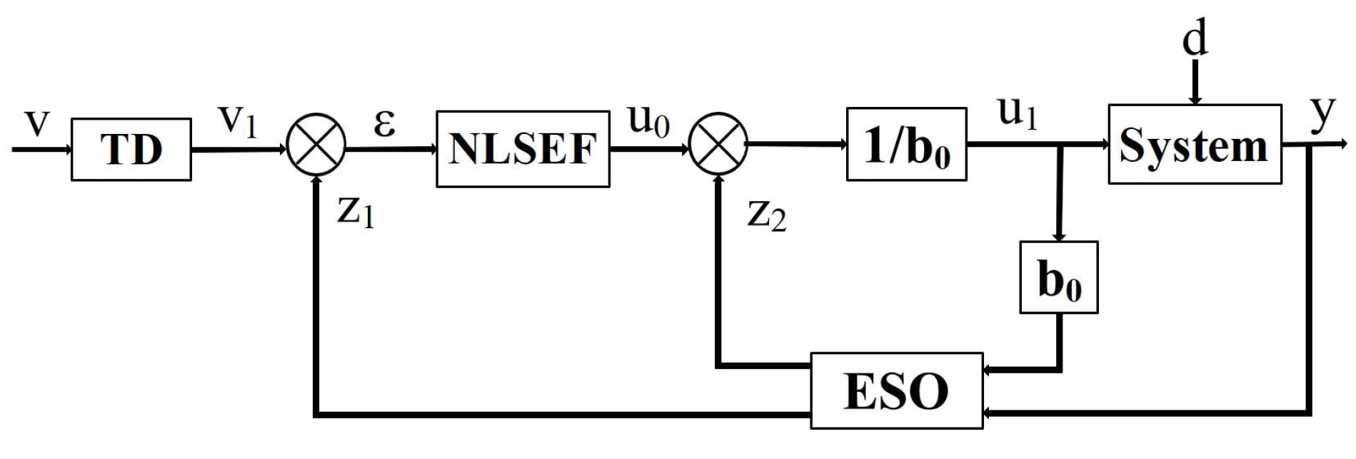
For the design of the speed controller, the variable to be controlled is the rotor speed , and the controller output is the electromagnetic torque, which is a function of q-axis currents, . Then, we can consider that the q-axis currents are the indirect outputs of the controller system, and all other factors are considered to be system disturbances. The block diagram of the ADRC speed controller for the 5-phase PMSM can be structured as described in Figure 2
where is the tracking signal of the speed reference , describe the error signal of speed loop. is the output of the NLSEF and u is the referential torque compensated by the estimated disturbance. and represent the tracking signal of and the estimated disturbance, respectively.
4.2. ADRC Controller Current Loop
In this section, we apply an ADRC to the current system of PMSM to achieve the robust control system design. Based on the mathematical model of PMSM, the state equation of current loop can be described by:
with is the control input, is the state variable, y is the system’s output, represent the nonlinear terms.
Following the same approach as for the speed control loop, the state Equation (31) can be expressed as follows:
where represents the total disturbances which includes non-linearity, external and internal disturbances and all other terms other than the control inputs.
5. Simulation Results
The ADRC control performance is compared simultaneously with that of LADRC and the conventional PI regulator to show the properties of each regulator and their capabilities. The Simulation were carried out in Matlab/Simulink platform. The PMSM and EV numerical parameters are presented in Table 1 and Table 2.
For comparison purposes, the following fitness functions are defined to study the regulators performance [43]:
Equations (33)–(36) present the Integral of the Square Error (ISE), the Integral of Absolute Error (IAE), the Integral of the Time-weighted Absolute Error (ITAE), and the Integral of the Time Square Error (ITSE), respectively [44].
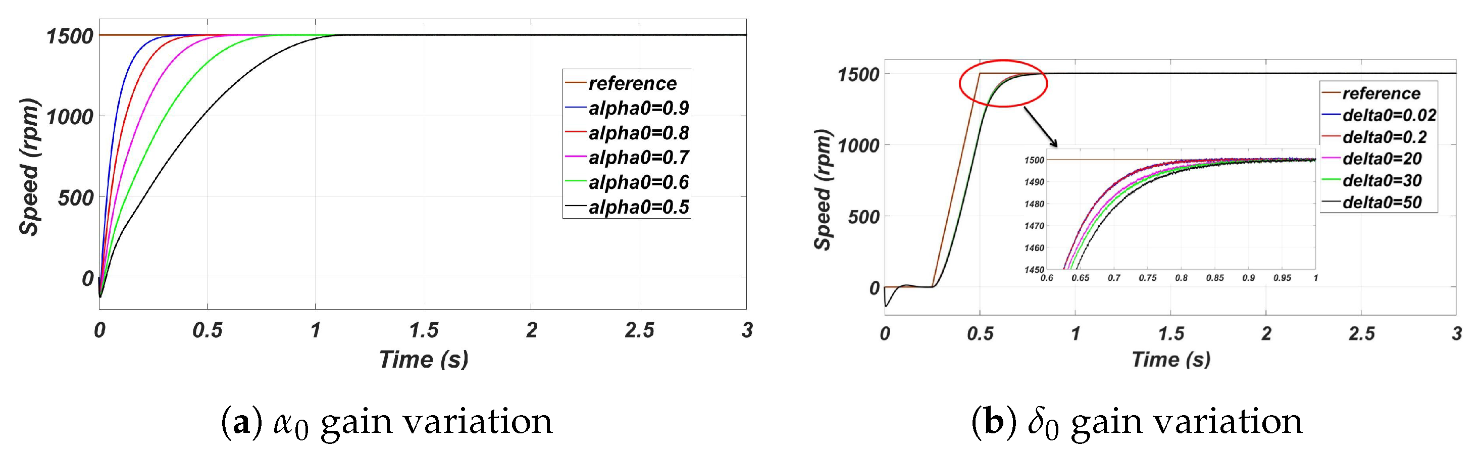
As already announced, the control of PMSM requires the use of five control block for both of currents and rotor speed, with an adjustment of a significant number of gains. Then, it is important to analysis the effect of variation of control parameters on PMSM operation. As presented in Equation (9), nonlinear law used in ADRC depends mainly on and . For , the time response increase and the signal track rapidly its reference to the increasing of gain which improve the control efficiency as shown in Figure 3a. Also, the control law depends on variation, where the time response increase with decreasing of as presented in Figure 3b.
To overcome the complexity of chosing the adequate gains, the LADRC was proposed to minimize the number of parameters to be adjusted and to simplify the control approach.
5.1. Speed and Load Torque Variation
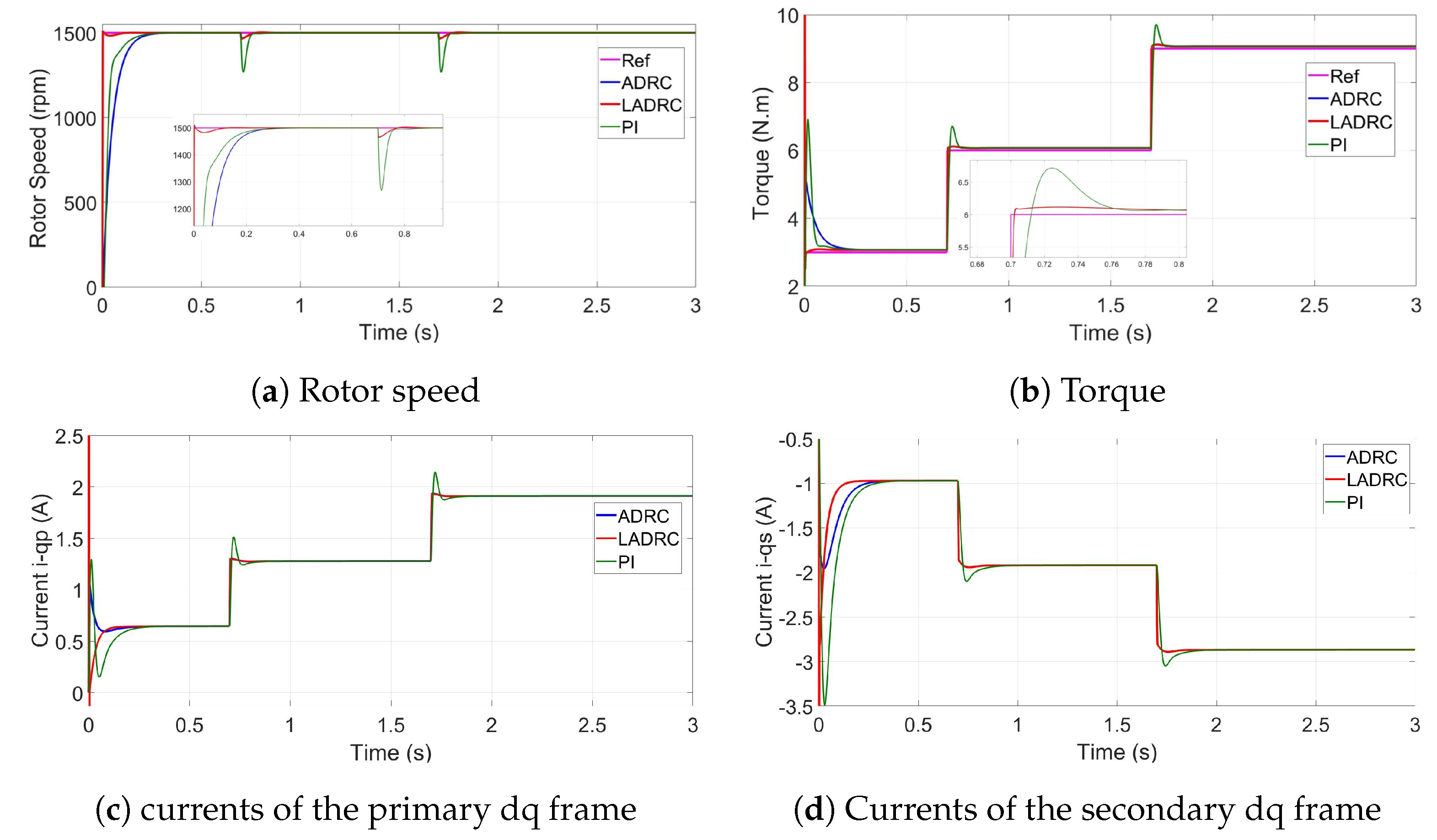
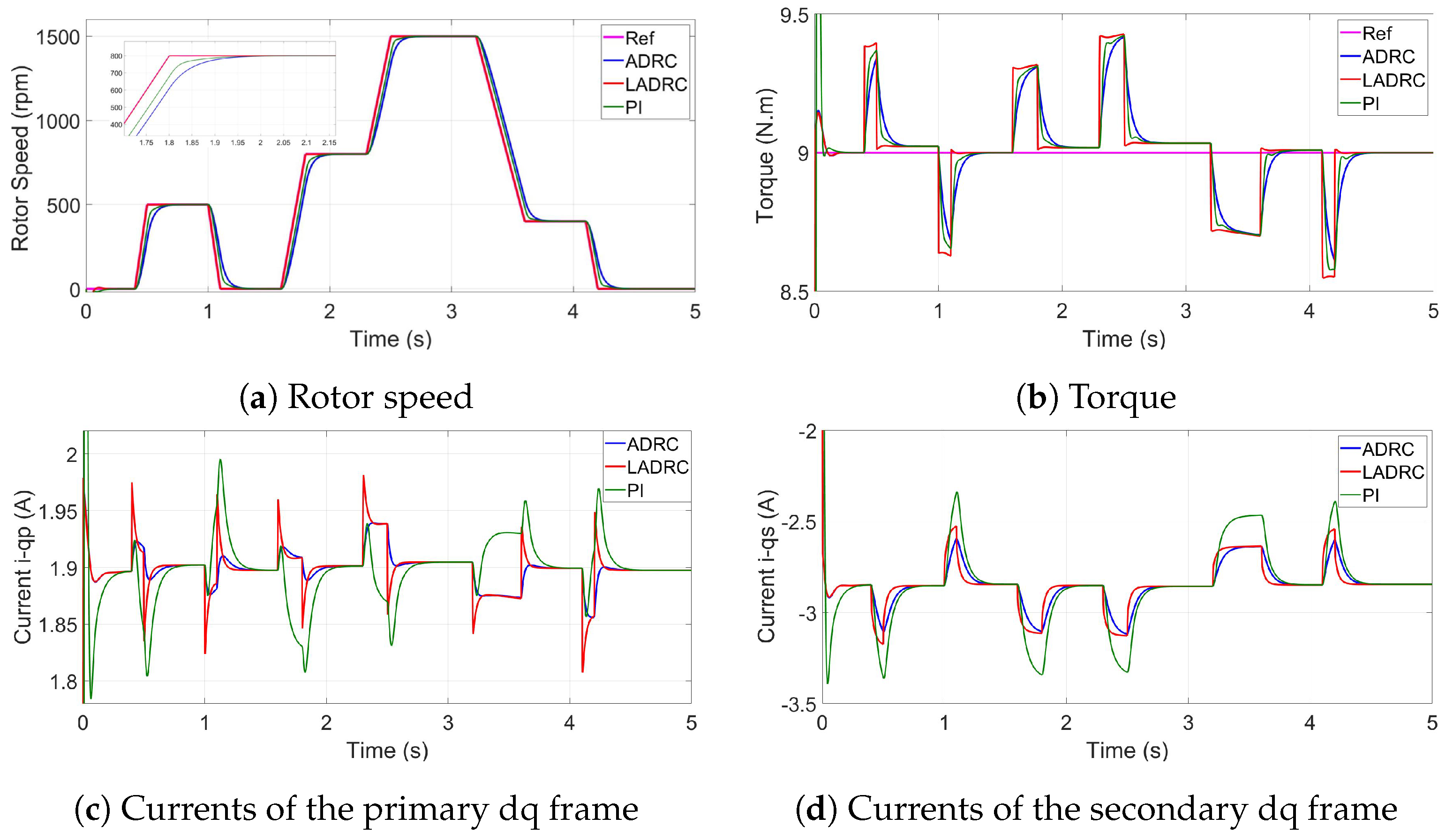
Figure 4 and Figure 5 present the respectively the speed, electromagnetic torque and the q-axes currents responses during the motor operation. Firstly, the speed was maintained to 1500 RPM with a variable torque, which progressively increases until it reaches its nominal value, as is shown in Figure 4. In the second case, the load torque was set to be constant with a speed variation, as presented in Figure 5.
The three regulators, ADRC, LADRC and the PI show a high tracking performance where the physical parameters track perfectly its references, especially in the steady state. The difference between the three regulators appears in the transient state. In the case of Pi regulator, a reduction in response time is usually accompanied by a significant overshoot, whereas the resolution of this overshoot produces a longer response time or even a delay in the system, which is not the case for the ADRC and LADRC regulators as shown in the following simulation. The ADRC regulator presents a response time that is very close to that of PI, but with a reduced overshoot. By simplifying the structure of the ADRC and minimizing regulation parameters, the LADRC combine between the both characteristics: the stability and the faster response. It was totally remarkable that LADRC presents a better performance than the standard ADRC and the traditional PI regulator, with a faster speed response as presented in both of Figure 4 and Figure 5.
Also, we notice in Figure 4c,d and Figure 5c,d, that both of the ADRC and LADRC regulate the q axis currents to track their references so they can adapt perfectly to those variations. The performance of each regulator is given Table 3, Table 4 and Table 5.
Performance indices of speed, , and are compared in case of starting stage, load torque and speed variations. The lowest performance indices for IAE, ISE, ITAE, and ITSE values prove the efficiency of proposed control strategy to achieve the highest tracking performance. These simulation results clearly show that the best control performance is achieved with ADRC and LADRC.
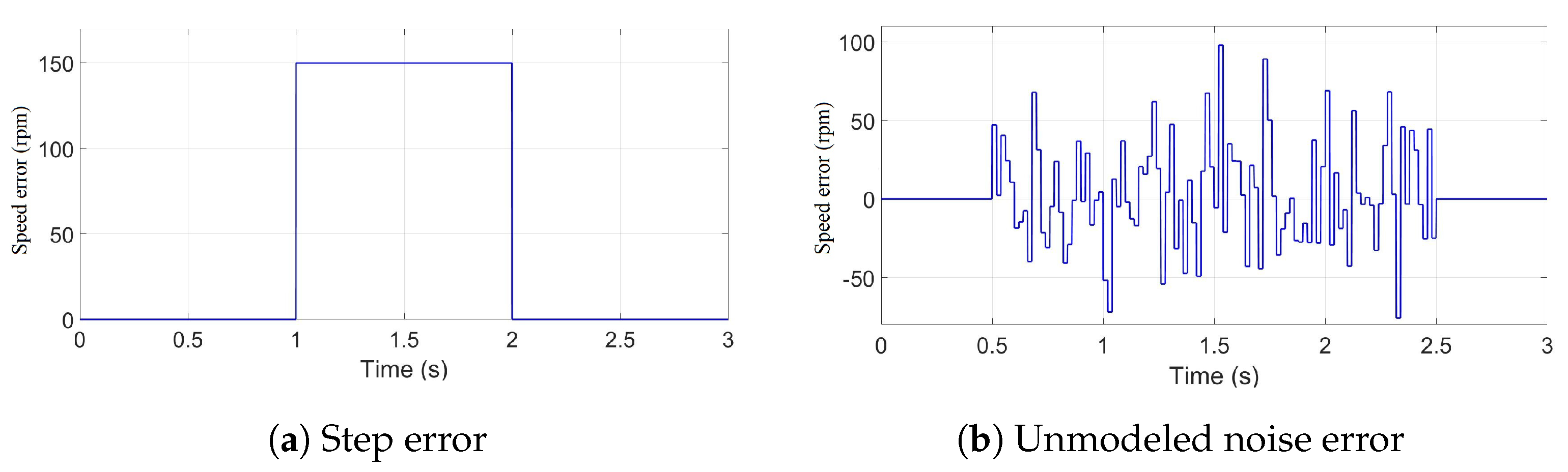
5.2. Speed Sensor Failure
In this section, the proposed control strategies are tested under speed sensor failure conditions. In this context, Figure 6 illustrates the additive signals that describe the considered sensor failures. The first signal, inserted to the rotor speed sensor output, represents a simple step with an amplitude equal to 150 RPM (Figure 6a), and the second one constitute an unmodeled noise with an amplitude below of the nominal speed.
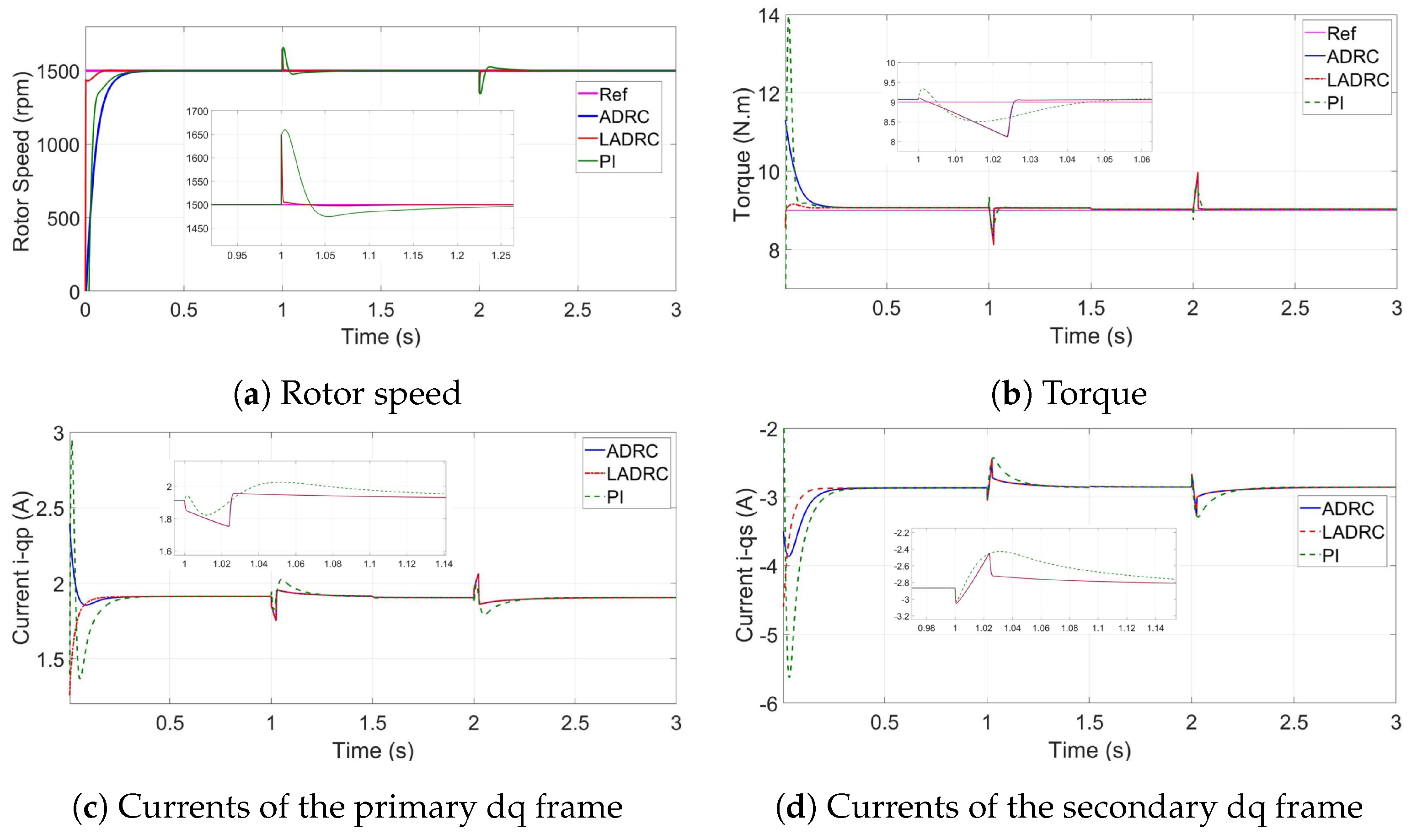
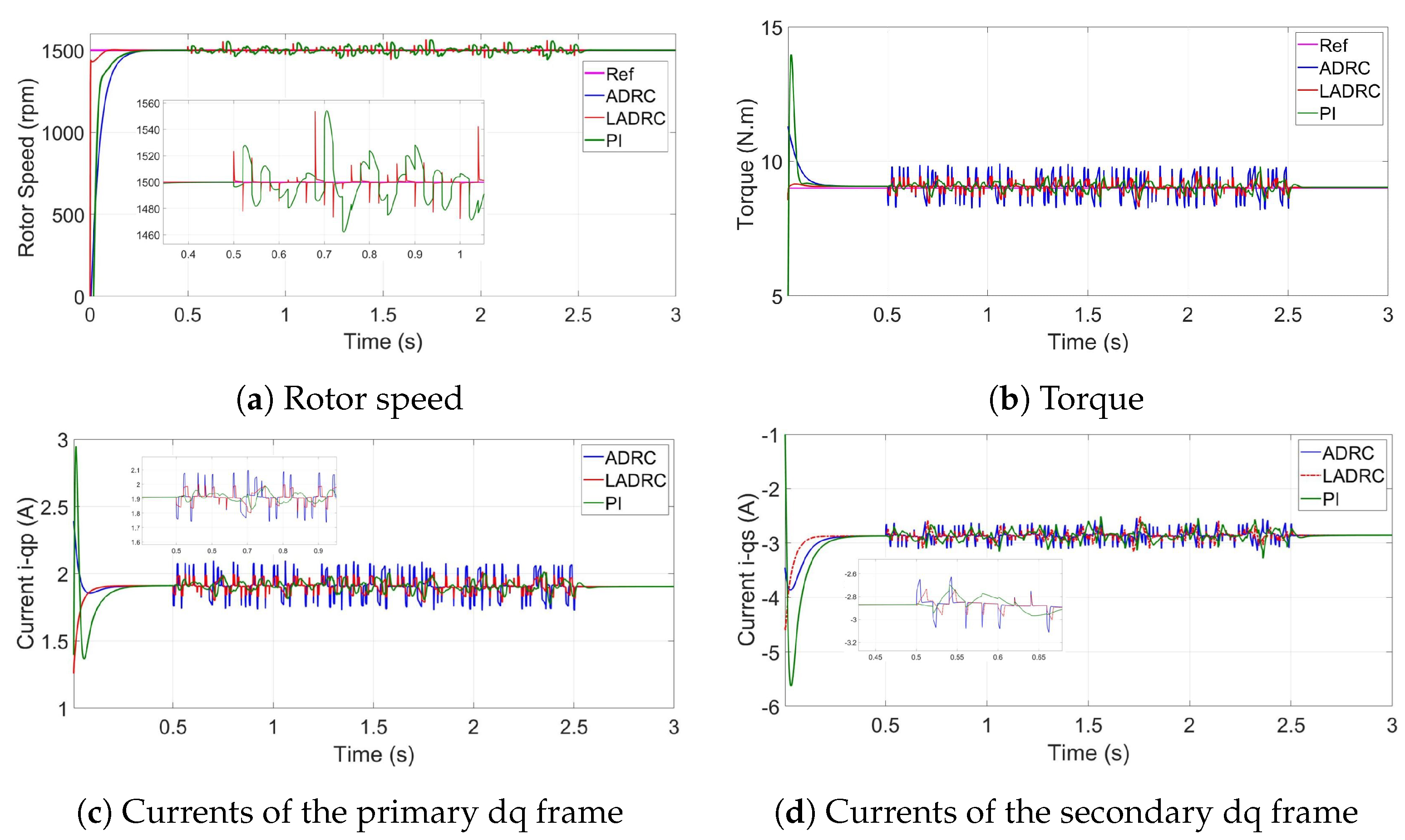
Figure 7 and Figure 8 illustrate the PMSP rotor speed, torque, and currents when considering speed sensor failures.
In the obtained simulation results, it can be noted that the 5-phase PMSM achieves very interesting tracking performance in terms of speed and torque despite the speed sensor failure. Indeed, the 5-phase PMSM keeps its speed and produced electromagnetic torque too smooth, as in the healthy mode, and rapidly compensate the difference between the reference signal and the faulty one. Using the ESO, included in the ADRC controller, the sensor failure can be estimated in real time as a part of the total disturbance affecting the motor, and compensated by the control law to ensure the system prescribed performance. This mechanism justifies the choice of the ADRC controller as a resilient control strategy, in addition to its robustness ability. These simulations results clearly highlight the robustness and resilience control performance of the 5-phase PMSM thanks to the use of the ADRC and LADRC.
5.3. Simulation Results Using Driving Cycles
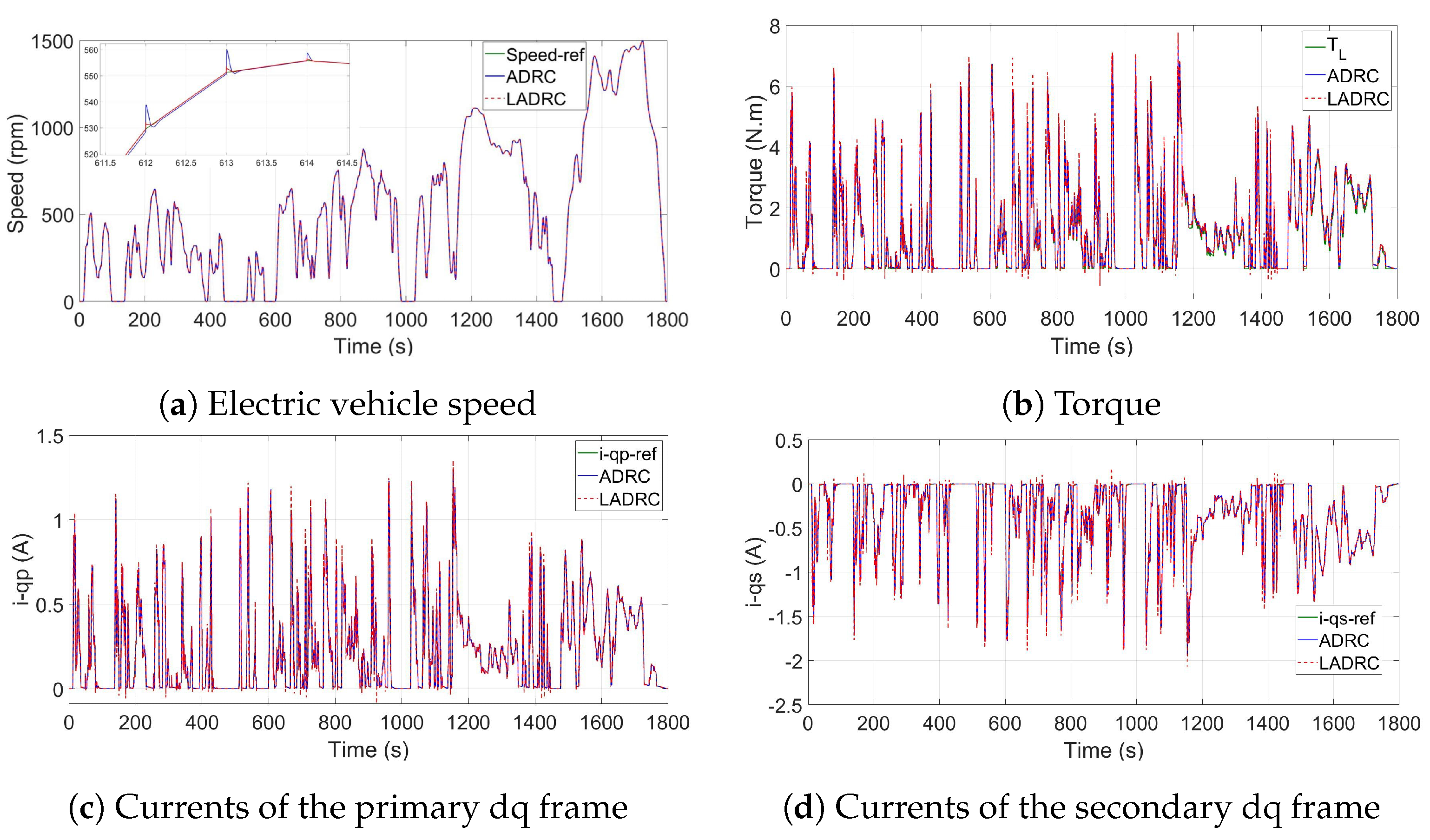
To test the validity of this control strategy, the proposed system operation will be tested with the Worldwide Harmonized Light Vehicle Test Procedure (WLTP) developed by the European Union [45]. This developed driving cycle is based on real-driving data, gathered from around the world [45,46]. As shown in Figure 9, WLTP is composed of four different parts with various average speeds: low, medium, high and extra high. Each one of those parts contains a variety of driving phases, stops, acceleration and braking phases.
It can be noted from the simulation results that because of the TD arrangement and the NLSEF, the PMSM can start continuously without overshoot but with the slow speed response.
In case of LADRC with elimination of TD, the system presents a neglected overshoot in a transient state, but it reaches quickly their reference value and have great stability in the steady state. The simulation results demonstrated the efficiency of suggested control strategy and the characteristics of each one in terms of fast tracking and robustness for internal and external disturbances.
6. Conclusions
This paper dealt with the active disturbance rejection control of a 5-Phase PMSM-based electric vehicle. In this context, the tracking capability and the resilient control performance of the proposed ADRC technique were investigated in different operation conditions and compared to its simplified structure presented by the linear ADRC and to the traditional PI controller. Standard forms of ADRC and Linear ADRC were implemented to control the speed and current considering rotor speed and load torque variations. Despite the difference between the two models, they have the same operating principle. Based on estimation and compensation of external and internal disturbances, they ensured higher performance and robustness compared to the PI controller. In faulty speed sensor conditions, the failure was estimated by the ESO as a part of the total disturbance and compensated in the real-time using the control law. According to the achieved simulation results, it was shown that the linear ARDC seems to be the most promising control approach for real-world application implementation as it allows leading to better control performance compared to ADRC and PI controllers.
Author Contributions
Conceptualization, A.H., S.B.E., Z.Z., and M.B.; Methodology, A.H., S.B., Z.Z., and M.B.; Software, A.H.; Validation, A.H., S.B., and Y.B.; Formal Analysis, A.H., S.B.E., and M.B.; Investigation, A.H.; Writing—Original Draft Preparation, A.H.; Writing—Review & Editing, A.H., S.B.E., Y.B., Z.Z., M.B., and M.N.A.; Supervision, M.N.A. All authors have read and agreed to the published version of the manuscript.
Funding
This work received no funding.
Acknowledgments
This work was supported by the Ministry of Higher Education and Scientific Research of Tunisia.
Conflicts of Interest
The authors declare no conflict of interest.
Nomenclature
| p, s | primary and secondary fictitious machine, respectively, in the dq frame., | Linear Active Disturbance Rejection Controller. | |||
| v | Stator voltage, | Torque of wheel. | |||
| i | Stator currents, | Torque of motor. | |||
| Electromagnetic torque, | Efficiency coefficient. | ||||
| L | Virtual machine inductance, | Gear ratio. | |||
| V | Driving velocity, | Electric Vehicle. | |||
| a | Vehicle acceleration, | Tracking Differentiator. | |||
| Rolling resistance force, | Extended State Observer. | ||||
| Acceleration force, | Non-Linear State Error Feedback. | ||||
| Aerodynamic drag force, | Permanent Magnet Synchronous Motor. | ||||
| Rotational speed of wheel, | Active Disturbance Rejection Controller. | ||||
| Rotational speed of motor, |
References
- Hezzi, A.; Elghali, S.B.; Salem, Y.B.; Abdelkrim, M.N. Control of five-phase PMSM for electric vehicle application. In Proceedings of the 2017 18th International Conference onSciences and Techniques of Automatic Control and Computer Engineering (STA), Monastir, Tunisia, 21–23 December 2017; pp. 205–211. [Google Scholar]
- Mekri, F.; Ben Elghali, S.; Charpentier, J.F.; Kestelyn, X.; Benbouzid, M. A New Control Strategy of 5-Phase PM Motor under Open-Circuited Phase Based on High Order Sliding Mode and Current References Real-Time Generation. Electr. Power Components Syst. 2019, 47, 261–274. [Google Scholar] [CrossRef]
- Mekri, F.; Elghali, S.B.; Charpentier, J.F. Analysis, simulation and experimental strategies of 5-phase permanent magnet motor control. Arch. Electr. Eng. 2019, 68, 629–641. [Google Scholar]
- Hezzi, A.; Bensalem, Y.; Zerrougui, M.; Elghali, S.B.; Abdelkrim, M.N. Sensorless Control Strategy for Five-Phase PMSM based on UIO for Linear Parameter Varying System. In Proceedings of the 2020 17th International Multi-Conference on Systems, Signals & Devices (SSD), Rabat-Salé, Morocco, 4–7 March 2020. [Google Scholar]
- Han, J. From PID to active disturbance rejection control. IEEE Trans. Ind. Electron. 2009, 56, 900–906. [Google Scholar] [CrossRef]
- Herbst, G. Simulative Study on Active Disturbance Rejection Control (ADRC) as a Control Tool for Practitioners. Electronics 2012, 2, 246–279. [Google Scholar] [CrossRef]
- Zhou, Z.; Ben Elghali, S.; Benbouzid, M.; Amirat, Y.; Elbouchikhi, E.; Feld, G. Control Strategies for Tidal Stream Turbine Systems – A Comparative Study of ADRC, PI, and High-Order Sliding Mode Controls. In Proceedings of the (IES), IECON 2019 45th Annual Conference of the IEEE Industrial Electronics Society, Lisbon, Portugal, 14–17 October 2019. [Google Scholar]
- Feng, G.; Liu, Y.F.; Huang, L. A new robust algorithm to improve the dynamic performance on the speed control of induction motor drive. IEEE Trans. Power Electron. 2004, 19, 1614–1627. [Google Scholar] [CrossRef]
- Zhang, C.; Chen, Y. Tracking control of ball screw drives using ADRC and equivalent-error-model-based feedforward control. IEEE Trans. Ind. Electron. 2016, 63, 7682–7692. [Google Scholar] [CrossRef]
- Lei, P.; Liao, X.B.; Huang, L.H.; Gong, C.H. Research of ADRC in Application to the Servo System of Self-propelled Gun. Appl. Mech. Mater. 2015, 713, 730–733. [Google Scholar] [CrossRef]
- Zhou, X.; Cui, H.; Ma, Y.; Gao, Z. The research on energy conservation controller for asynchronous motor based on ADRC. In Proceedings of the 2017 29th Chinese Control And Decision Conference (CCDC), Chongqing, China, 28–30 May 2017; pp. 4010–4014. [Google Scholar]
- Kuang, Z.; Du, B.; Cui, S.; Chan, C. Speed Control of Load Torque Feedforward Compensation Based on Linear Active Disturbance Rejection for Five-Phase PMSM. IEEE Access 2019, 7, 159787–159796. [Google Scholar] [CrossRef]
- Ren, L.; Mao, C.; Song, Z.; Liu, F. Study on active disturbance rejection control with actuator saturation to reduce the load of a driving chain in wind turbines. Renew. Energy 2019, 133, 268–274. [Google Scholar] [CrossRef]
- Ortiz, A.; Orozco, S.; Zannatha, I. ADRC controller for weightlifter Humanoid robot. In Proceedings of the 2019 International Conference on Electronics, Communications and Computers (CONIELECOMP), Cholula, Mexico, 27 February–1 March 2019; pp. 41–46. [Google Scholar]
- Hezzi, A.; Ben Elghali, S.; Bensalem, Y.; Zhou, Z.; Benbouzid, M.; Abdelkrim, M.N. Active Disturbance Rejection Control of a Five-Phase PMSM with Parameters Variation. In Proceedings of the (IES), IECON 2019 45th Annual Conference of the IEEE Industrial Electronics Society, Lisbon, Portugal, 14–17 October 2019. [Google Scholar]
- Sira-Ramírez, H.; Linares-Flores, J.; García-Rodríguez, C.; Contreras-Ordaz, M.A. On the control of the permanent magnet synchronous motor: An active disturbance rejection control approach. IEEE Trans. Control. Syst. Technol. 2014, 22, 2056–2063. [Google Scholar] [CrossRef]
- Rong, Z.l.; Huang, Q. A new PMSM speed modulation system with sliding mode based on active-disturbance-rejection control. J. Cent. South Univ. 2016, 23, 1406–1415. [Google Scholar] [CrossRef]
- Yuan, Q.; Liu, Z.; Chen, H.; Tian, Y. A cruise control for electric vehicle based on ADRC controller considering driver’s behavior. In Proceedings of the IECON 2017-43rd Annual Conference of the IEEE Industrial Electronics Society, Beijing, China, 29 October–1 November 2017; pp. 4597–4602. [Google Scholar]
- Wen, J.P.; Zhang, C.W. Research on modeling and control of regenerative braking for brushless DC machines driven electric vehicles. Math. Probl. Engi. 2015, 2015. [Google Scholar] [CrossRef] [Green Version]
- Lin, D.; Luo, W.; Zhang, H. Active disturbance rejection controller of BLDCM in electric vehicle. In Proceedings of the 2011 International Conference on Electrical Machines and Systems, Beijing, China, 20–23 August 2011; pp. 1–4. [Google Scholar]
- Byington, C.S.; Watson, M.; Edwards, D.; Stoelting, P. A model-based approach to prognostics and health management for flight control actuators. In Proceedings of the 2004 IEEE Aerospace Conference Proceedings (IEEE Cat. No. 04TH8720), Big Sky, MT, USA, 6–13 March 2004; pp. 3551–3562. [Google Scholar]
- Tabbache, B.; Rizoug, N.; Benbouzid, M.; Kheloui, A. A control reconfiguration strategy for post-sensor FTC in induction motor-Based EVs. IEEE Trans. Veh. Technol. 2013, 62, 965–971. [Google Scholar] [CrossRef] [Green Version]
- Tabbache, B.; Benbouzid, M.; Kheloui, A.; Bourgeot, J. DSP-based sensor fault detection and post fault-tolerant control of an induction motor-based electric vehicle. Int. J. Veh. Technol. 2012, 2012, 1–7. [Google Scholar] [CrossRef] [Green Version]
- Trabelsi, M.; Boussak, M.; Benbouzid, M. Multiple criteria for high performance real-time diagnostic of single and multiple open-switch faults in AC-motor drives: Application to IGBT-based voltage source inverter. Electr. Power Syst. Res. 2017, 144, 136–149. [Google Scholar] [CrossRef]
- Pham, H.T.; Bourgeot, J.M.; Benbouzid, M. Comparative investigations of sensor fault-tolerant control strategies performance for marine current turbine applications. IEEE J. Ocean. Eng. 2018, 43, 1024–1036. [Google Scholar] [CrossRef]
- Bolvashenkov, I.; Herzog, H.G.; Ismagilov, F.; Vavilov, V.; Khvatskin, L.; Frenkel, I.; Lisnianski, A. Fault Tolerant Multi-phase Permanent Magnet Synchronous Motor for the More Electric Aircraft. In Fault-Tolerant Traction Electric Drives; Springer: Berlin, Germany, 2020; pp. 73–92. [Google Scholar]
- Nounou, K.; Charpentier, J.; Marouani, K.; Benbouzid, M.; Kheloui, A. Emulation of an electric naval propulsion system based on a multiphase machine under healthy and faulty operating conditions. IEEE Trans. Veh. Technol. 2018, 67, 6895–6905. [Google Scholar] [CrossRef]
- Song, Z.; Li, J.; Ouyang, M.; Gu, J.; Feng, X.; Lu, D. Rule-based fault diagnosis of hall sensors and fault-tolerant control of PMSM. Chin. J. Mech. Eng. 2013, 26, 813–822. [Google Scholar] [CrossRef]
- Deng, F.; Guan, Y. PMSM Vector Control Based on Improved ADRC. In Proceedings of the 2018 IEEE International Conference of Intelligent Robotic and Control Engineering (IRCE), Lanzhou, China, 24–27 August 2018; pp. 154–158. [Google Scholar]
- Du, B.; Wu, S.; Han, S.; Cui, S. Application of linear active disturbance rejection controller for sensorless control of internal permanent-magnet synchronous motor. IEEE Trans. Ind. Electron. 2016, 63, 3019–3027. [Google Scholar] [CrossRef]
- Ahi, B.; Haeri, M. Linear active disturbance rejection control from the practical aspects. Ieee/Asme Trans. Mechatronics 2018, 23, 2909–2919. [Google Scholar] [CrossRef]
- Hezzi, A.; Bensalem, Y.; Elghali, S.B.; Abdelkrim, M.N. Sliding Mode Observer based sensorless control of five phase PMSM in electric vehicle. In Proceedings of the 2019 19th International Conference on Sciences and Techniques of Automatic Control and Computer Engineering (STA), Sousse, Tunisia, 24–26 March 2019; pp. 530–535. [Google Scholar]
- Zheng, Q. On Active Disturbance Rejection Control; Stability Analysis and Applications in Disturbance Decoupling Control. Ph.D. Thesis, Cleveland State University, Cleveland, OH, USA, July 2009. [Google Scholar]
- Zheng, Q.; Chen, Z.; Gao, Z. A practical approach to disturbance decoupling control. Control. Eng. Pract. 2009, 17, 1016–1025. [Google Scholar] [CrossRef] [Green Version]
- Moujahed, M.; Azza, H.B.; Frifita, K.; Jemli, M.; Boussak, M. Fault detection and fault-tolerant control of power converter fed PMSM. Electr. Eng. 2016, 98, 121–131. [Google Scholar] [CrossRef]
- Lei, Y.; Xu, J.; Hao, Q. Application of ADRC in Stability Control of Tank Gun System. In Proceedings of the 2018 IEEE 7th Data Driven Control and Learning Systems Conference (DDCLS), Enshi, China, 25–27 May 2018; pp. 670–675. [Google Scholar]
- Qiu, Z.; Xiao, J.; Wang, S. Active-disturbance rejection control based on a novel sliding mode observer for PMSM speed and rotor position. J. Vibroeng. 2015, 17, 4603–4617. [Google Scholar]
- Hezzi, A.; Ben Elghali, S.; Zhou, Z.; Elbouchikhi, E.; Benbouzid, M. Linear ADRC for Speed Control of 5-Phase PMSM-based Electric Vehicles. In Proceedings of the 2020 International Conference on Electrical and Technologies, ICEIT, Rabat-Salé, Morocco, 4–7 March 2020. [Google Scholar]
- Zhao, L.; Yang, Y.; Xia, Y.; Liu, Z. Active disturbance rejection position control for a magnetic rodless pneumatic cylinder. IEEE Trans. Ind. Electron. 2015, 62, 5838–5846. [Google Scholar] [CrossRef]
- Zheng, Q.; Gaol, L.Q.; Gao, Z. On stability analysis of active disturbance rejection control for nonlinear time-varying plants with unknown dynamics. In Proceedings of the 2007 46th IEEE Conference on Decision and Control, New Orleans, LA, USA, 12–14 December 2007; pp. 3501–3506. [Google Scholar]
- Gao, Z. Active disturbance rejection control: A paradigm shift in feedback control system design. In Proceedings of the 2006 American control conference, Minneapolis, MN, USA, 4–16 June 2006. [Google Scholar]
- Guo, B.; Bacha, S.; Alamir, M. A review on ADRC based PMSM control designs. In Proceedings of the IECON 2017-43rd annual conference of the IEEE industrial electronics society, Beijing, China, 29 October–1 November 2017; pp. 1747–1753. [Google Scholar]
- Zhou, Z.; Elghali, S.B.; Benbouzid, M.; Amirat, Y.; Elbouchikhi, E.; Feld, G. Tidal stream turbine control: An active disturbance rejection control approach. Ocean. Eng. 2020, 202, 107190. [Google Scholar] [CrossRef]
- Almabrok, A.; Psarakis, M.; Dounis, A. Fast Tuning of the PID Controller in An HVAC System Using the Big Bang–Big Crunch Algorithm and FPGA Technology. Algorithms 2018, 11, 146. [Google Scholar] [CrossRef] [Green Version]
- Cubito, C.; Millo, F.; Boccardo, G.; Di Pierro, G.; Ciuffo, B.; Fontaras, G.; Serra, S.; Otura Garcia, M.; Trentadue, G. Impact of Different Driving Cycles and Operating Conditions on CO2 Emissions and Energy Management Strategies of a Euro-6 Hybrid Electric Vehicle. Energies 2017, 10, 1590. [Google Scholar] [CrossRef]
- Bodisco, T.; Zare, A. Practicalities and Driving Dynamics of a Real Driving Emissions (RDE) Euro 6 Regulation Homologation Test. Energies 2019, 12, 2306. [Google Scholar] [CrossRef] [Green Version]
Figure 1.
Block diagram of ADRC for a 5-phase PMSM.

Figure 2.
Schematic diagram of standard ADRC controller.

Figure 3.
Control law variation.

Figure 4.
PMSM performance with load torque variation.

Figure 5.
PMSM performance with speed variation.

Figure 6.
Failures of speed sensor.

Figure 7.
PMSM performance in the first faulty mode.

Figure 8.
PMSM performance in the second faulty mode.

Figure 9.
PMSM performance under WLTP drive cycle.


Table 1.
5-phase PMSM Parameters.
| Symbol | Parameter | Value |
|---|---|---|
| Number of pole pairs | 2 | |
| R | Stator resistance | |
| Principal machine inductance | 0.1228 H | |
| Seconder machine inductance | 0.0222 H | |
| First harmonic constants | 2 | |
| Third harmonic constants | ||
| J | Inertia moment | kg·m |
| B | Viscous friction coefficient | 0.000457 N.m.s/rad |
Table 2.
EV Parameters.
| Symbol | Parameter | Value |
|---|---|---|
| Rolling resistance coefficient | ||
| m | Mass of the EV | 1000 kg |
| Air density | 1.2 kg/m | |
| Frontal area | m | |
| Drag coefficient | ||
| g | Gravity acceleration | 9.81 m/s2 |
| r | Tyre radius | 0.3 m |
Table 3.
Performance indices of the speed control loop.
| Starting Stage | Torque Disturbance | Speed Variation | ||
|---|---|---|---|---|
| LADRC | IAE | 0.0207 | 1.3897 | 0.4374 |
| ISE | 0.0072 | 30.645 | 1.1128 | |
| ITAE | 0.0043 | 1.0190 | 0.2112 | |
| ITSE | 0.0013 | 22.003 | 0.5233 | |
| ADRC | IAE | 2.2360 | 1.4314 | 24.242 |
| ISE | 54.016 | 32.315 | 3406.7 | |
| ITAE | 0.4780 | 1.0497 | 12.068 | |
| ITSE | 10.325 | 23.205 | 1655.4 | |
| PI | IAE | 1.4552 | 6.8994 | 15.557 |
| ISE | 19.674 | 1065.1 | 1521.2 | |
| ITAE | 0.3210 | 5.0133 | 7.5860 | |
| ITSE | 3.8406 | 763.27 | 720.50 |
Table 4.
Performance indices of the current control loop.
| Starting Stage | Torque Disturbance | Speed Variation | ||
|---|---|---|---|---|
| LADRC | IAE | 0.0188 | 0.1280 | 0.0053 |
| ISE | 0.0060 | 0.0802 | 0.00017 | |
| ITAE | 0.00067 | 0.0770 | 0.0024 | |
| ITSE | 0.00011 | 0.0481 | 0.00007 | |
| ADRC | IAE | 0.0113 | 0.1280 | 0.0037 |
| ISE | 0.0017 | 0.0802 | 0.00004 | |
| ITAE | 0.00075 | 0.0770 | 0.0018 | |
| ITSE | 0.00003 | 0.0481 | 0.00002 | |
| PI | IAE | 0.0472 | 0.1367 | 0.0115 |
| ISE | 0.0160 | 0.0821 | 0.00062 | |
| ITAE | 0.0037 | 0.0834 | 0.0062 | |
| ITSE | 0.0008 | 0.0495 | 0.00033 |
Table 5.
Performance indices of in different operating conditions.
| Starting Stage | Torque Disturbance | Speed Variation | ||
|---|---|---|---|---|
| LADRC | IAE | 0.0562 | 0.1930 | 0.0332 |
| ISE | 0.0509 | 0.1811 | 0.0080 | |
| ITAE | 0.0021 | 0.1162 | 0.0156 | |
| ITSE | 0.0010 | 0.1087 | 0.0037 | |
| ADRC | IAE | 0.0957 | 0.1931 | 0.0329 |
| ISE | 0.0642 | 0.1811 | 0.0054 | |
| ITAE | 0.0069 | 0.1163 | 0.0170 | |
| ITSE | 0.0031 | 0.1087 | 0.0027 | |
| PI | IAE | 0.1942 | 0.2137 | 0.0637 |
| ISE | 0.2933 | 0.1896 | 0.0212 | |
| ITAE | 0.0139 | 0.1317 | 0.0329 | |
| ITSE | 0.0137 | 0.1148 | 0.0107 |
© 2020 by the authors. Licensee MDPI, Basel, Switzerland. This article is an open access article distributed under the terms and conditions of the Creative Commons Attribution (CC BY) license (http://creativecommons.org/licenses/by/4.0/).
Share and Cite
MDPI and ACS Style
Hezzi, A.; Ben Elghali, S.; Bensalem, Y.; Zhou, Z.; Benbouzid, M.; Abdelkrim, M.N. ADRC-Based Robust and Resilient Control of a 5-Phase PMSM Driven Electric Vehicle. Machines 2020, 8, 17. https://doi.org/10.3390/machines8020017
AMA Style
Hezzi A, Ben Elghali S, Bensalem Y, Zhou Z, Benbouzid M, Abdelkrim MN. ADRC-Based Robust and Resilient Control of a 5-Phase PMSM Driven Electric Vehicle. Machines. 2020; 8(2):17. https://doi.org/10.3390/machines8020017
Chicago/Turabian StyleHezzi, Abir, Seifeddine Ben Elghali, Yemna Bensalem, Zhibin Zhou, Mohamed Benbouzid, and Mohamed Naceur Abdelkrim. 2020. "ADRC-Based Robust and Resilient Control of a 5-Phase PMSM Driven Electric Vehicle" Machines 8, no. 2: 17. https://doi.org/10.3390/machines8020017
Note that from the first issue of 2016, this journal uses article numbers instead of page numbers. See further details here.