Equipment and Technology for Combined Ion–Plasma Strengthening of Cutting Tools


High-Efficiency Machining Technologies Department, Moscow State University of Technology “STANKIN”, Vadkovsky per. 3A, Moscow 127055, Russia
*
Author to whom correspondence should be addressed.
Machines 2018, 6(4), 58; https://doi.org/10.3390/machines6040058
Submission received: 17 October 2018
/
Revised: 4 November 2018
/
Accepted: 6 November 2018
/
Published: 9 November 2018
Abstract
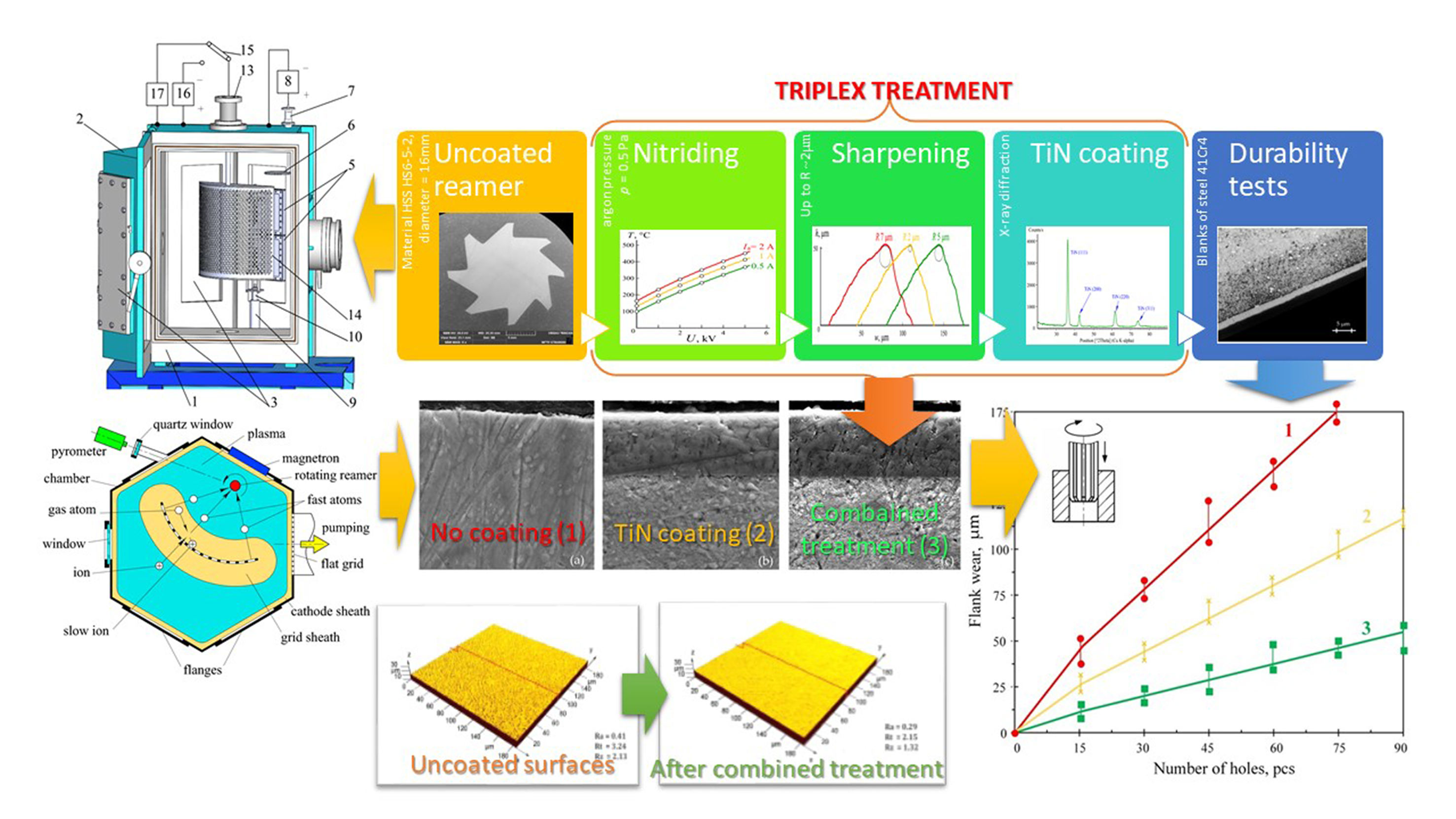
:A combined strengthening of cutting tools for finishing has been carried out in glow discharge plasma filling a process vacuum chamber. At the first stage, reamers rotating around the axis distanced from the magnetron targets at 8 cm were bombarded by fast argon atoms produced due to charge exchange collisions of ions accelerated in space charge sheathes between the plasma and a negatively biased to 3 kV grid with a 25 cm radius of its concave surface curvature. The reamer bombardment by fast neutral atoms led to a reduction of its cutting-edge radius from ~7 μm to ~2 μm. At the second stage, the reamer surface was nitrided within 1 h at a temperature of 500 °C stabilized by regulation of the negative bias voltage accelerating the nitrogen ions. At the third stage, a 3 μm thick TiN coating has been synthesized on the reamer bombarded by pulsed beams of 3 keV neutral atoms at a 50 Hz repetition rate of 50 μs wide pulses. After the combined strengthening, the cutting edge radius of the coated reamer amounted to ~5 μm and the roughness of the area machined by the reamer holes in blanks made of structural steel reduced by about 1.5 times.

1. Introduction
The useful life of tools, machine parts, and other products can be increased due to vacuum arc deposition [1,2,3,4,5] of wear-resistant TiN [6,7] and other coatings with a microhardness of ~25 GPa, whose manifold exceeds hardness of the product material. The thickness of wear-resistant coatings synthesized on tools for rough cutting usually does not exceed 5–7 μm. At a higher coating thickness, the typical radius of the tool-cutting edge R ~ 15 μm grows to R > 20 μm, which is representative of blunted tools. Prior to the coating synthesis, tools are heated and etched by metal ions accelerated from the arc discharge plasma at the gas pressure of 0.001 Pa by a negative bias voltage of ~1000 V applied to the tools. After the heating, nitrogen is admitted to the process chamber and, at the gas pressure of 0.1–1 Pa, a hard nitride coating is synthesized on the tools under a negative bias voltage of ~100 V.
In order to improve the performance of the coated tools and increase their useful lifetime, they are nitrided prior to the coating deposition. A nitrided surface layer with a thickness by an order of magnitude exceeding the coating thickness exhibits a fatigue strength and high load-bearing capacity. This prevents plastic and elastic deformations of the tool surface as well as brittle rupture of the deposited coating [8,9,10]. The combined strengthening of cutting tools based on the vacuum arc, which includes pre-nitriding and deposition of the wear-resistant coating, can be carried out in the same vacuum chamber [11,12]. The tools are immersed in nitrogen plasma and heated up to an effective temperature of thermodiffusion 500–800 °C by ions accelerated from the plasma by a negative bias voltage applied to the tools. Depending on the tool mass, pre-nitriding takes about 0.5–1.5 h. Subsequent synthesis of wear-resistant coatings usually takes about 30 min.
In addition to the vacuum arc, magnetron sputtering systems [13,14,15,16,17] and hollow cathode sputtering systems [18,19,20,21,22] can be also used for the coating deposition. In all cases, the coating is bombarded during the synthesis by ions accelerated from the gas discharge plasma [23,24,25,26] or using broad beam sources of ions or fast gas atoms [27,28,29]. The bombardment improves adhesion and other properties of the coatings [30,31,32,33,34]. For example, when negative 45-kV pulses with 50 μs width and 50 Hz repetition rate are applied to a substrate made of high speed steel (HSS) instead of bias voltage ~80 V, the sputtered titanium nitride coating exhibits improved adhesion and nanostructure, a change of yellow color to brown, an increase in microhardness from 2500 HV to 5000 HV, and a decrease in internal stress [35,36,37].
The improvements of the tools for rough cutting achievable due to above combined ion–plasma processing, which includes nitriding and coating deposition, are also desirable in the case of a tool for finishing. However the latter is remarkable for a lower radius of the cutting edge, which amounts to R = 8–10 μm. Hence, deposition of a 3 μm thick wear-resistant titanium nitride coating would increase the radius up to R = 13 μm and make the tool blunt. To prevent blunting, the tool should be first sharpened and the radius of its cutting edge should be reduced down to R = 1–3 μm as was done in [27].
The present research is aimed at the development of combined ion–plasma processing technology and equipment for sharpening of a cutting tool by fast argon atoms, nitriding of the tool surface, and synthesis on the surface of the hard wear-resistant coating.
2. Materials and Methods
2.1. Experimental Setup
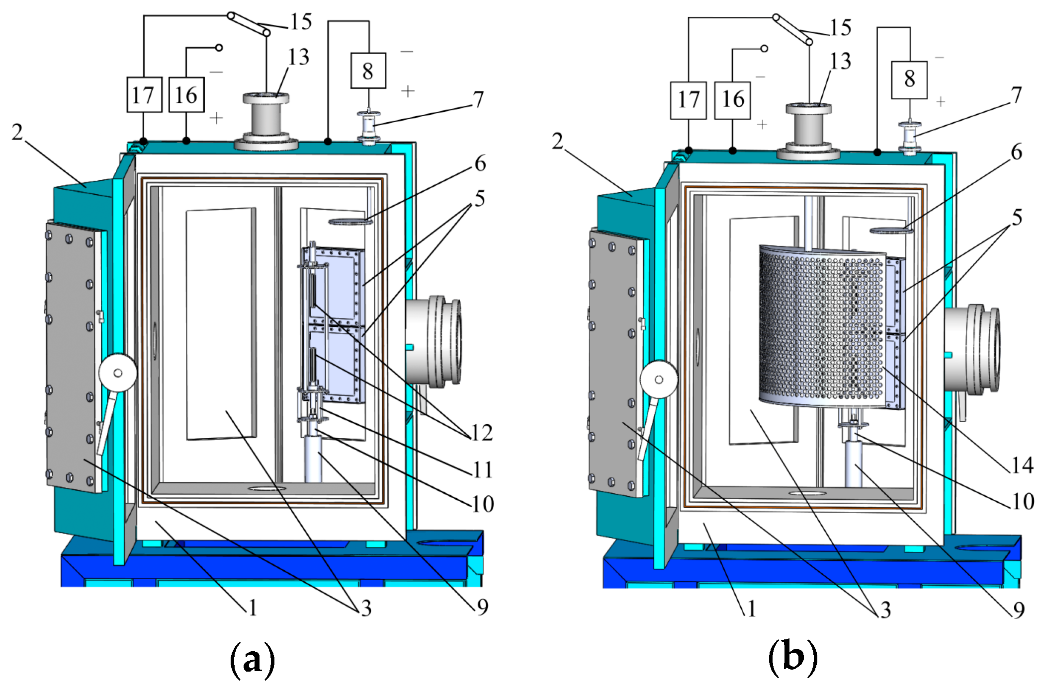
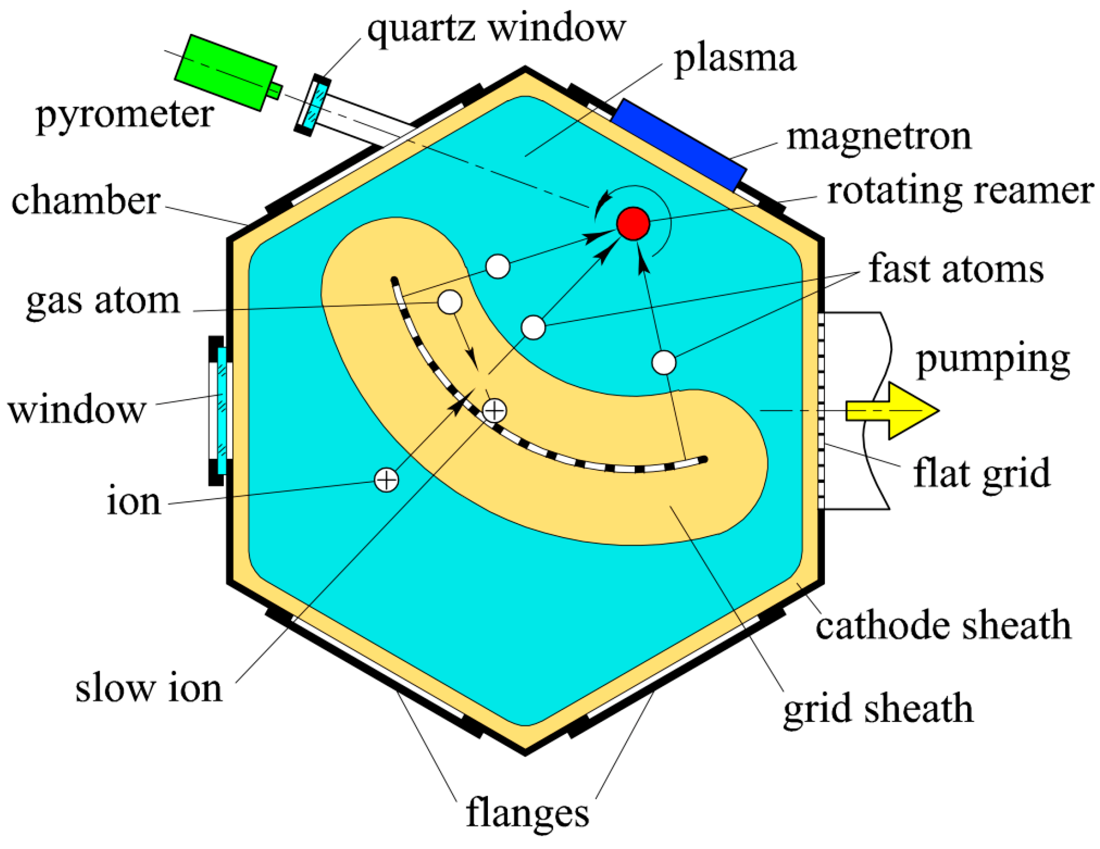
The investigations were carried out in a 850 mm high process vacuum chamber (1) shaped like a hexagonal prism with a 600 mm diameter incircle (Figure 1). The chamber has two doors (2) and on each door, there are two 600 × 200 mm2 rectangular windows. The windows of one door are hermetically closed with flanges (3). One flange of the other door is equipped with a quartz window 4 enabling a remote in-situ control of the temperature of the tool using pyrometer IMPAC IP 140 (LumaSense Technologies GmbH, Frankfurt am Main, Germany) and on the other flange are mounted two 180 mm wide and 200 mm high planar magnetrons (5). They form dual magnetron sputtering systems together with an AC 50 kHz power supply (not shown in Figure 1) connected between 140 × 160 mm2 titanium targets of the magnetrons. When one of the targets acts as an anode with a potential being close to that of the plasma filling the chamber, the second target acts as a sputter cathode, which is negative to the plasma. In half a period the targets change their roles. A disc anode (6) inside the chamber is connected through feedthrough (7) to the positive pole of a DC power supply (8) and its negative pole is connected to the grounded chamber. The power supply provides the discharge voltage 300–1200 V at a stabilized current of 1–4 A.
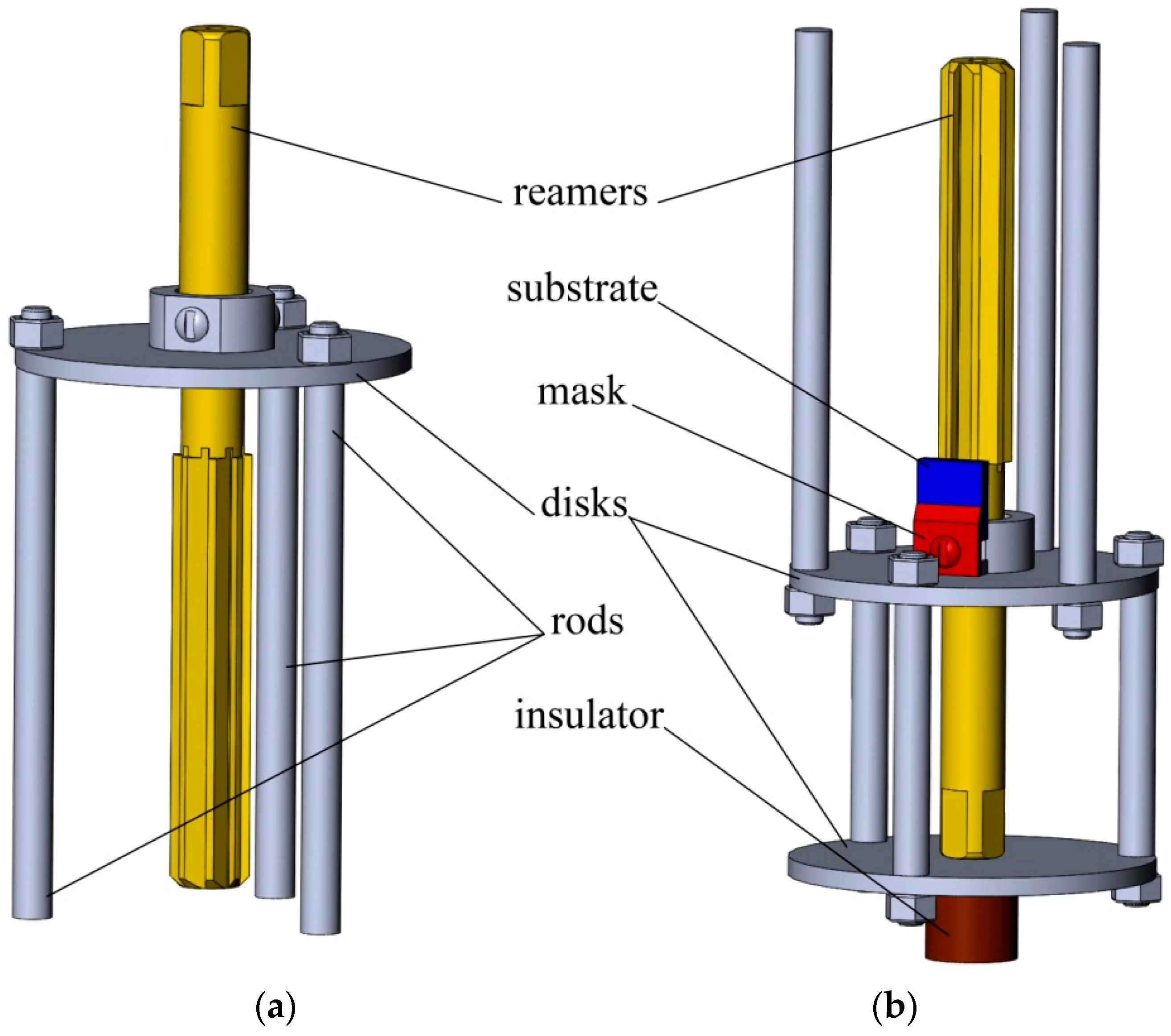
A product rotation system is mounted under the bottom of the chamber and fastened to axle (9) of the system through insulator (10), a holder (11) of two reamers (12) made of high-speed steel HS6-5-2 (Figure 2) produced by Moscow Tool Plant MIZ, PAO (Moscow, Russia). The reamer rotation speed amounts to 24 rpm. The insulator is screened from the metal vapor by a steel hollow cylinder mounted at the top of the axle. Axes of rotating reamers are distant at 8 cm from the magnetron targets. The holder comprises two 80 mm diameter discs connected with each other using three 8 mm diameter rods. A substrate made of high-speed steel HS6-5-2 with a mask used for measurement of the nitrided surface hardness and definition of the deposited coating thickness is fastened on the lower disc close to the reamer.
High-voltage feedthrough 13 is mounted at the top of the chamber and 40 cm high titanium grid 14 can be fastened to the feedthrough. The axis of its concave cylindrical surface coincides with the axis of the reamer’s rotation. The radius of the grid surface curvature is equal to 25 cm. The grid can be connected to the negative pole of the DC power supply 16 using switch 15; the DC power supply 16 provides stabilized voltage up to 3 kV at current up to 2 A, or to high-voltage pulse generator 17. The latter allows the application to the grid of high-voltage negative pulses with amplitude 1–10 kV, the width of 10–50 μs, and a repetition rate of 5–50 Hz. A schematic diagram of the vacuum chamber is presented in Figure 3.
The gas pressure in the chamber is measured in the pressure range 0.001–0.1 Pa by vacuummeter VIT-3 (Istok, Moscow, Russia) with gauge ionization converter PMI-2 (Istok, Moscow, Russia) and in the pressure range 0.1–5 Pa by MKS-vacuummeter (MKSI, Andover, MA, USA) with transducer BARATRON (MKSI, Andover, MA, USA). The gas is admitted to the chamber through a gas supply system (not shown in Figure 1) and is evacuated from the chamber through the grounded grid by a turbo-molecular pump, which ensures the residual gas pressure of 0.001 Pa. Using the gas supply system, the pressure inside the chamber can be regulated from 0.001 to 5 Pa.
2.2. Characterization of the Samples
The cutting edges were controlled using the optical 3D measuring system MicroCAD premium+ (GFMesstechnik GmbH, Teltow, Germany).
The thickness of the substrate and the height of the step between that covered by the mask and the coated surfaces of the substrate was measured using a stylus profiler DectakXT produced by Bruker Nano, Inc. (Billerica, MA, USA).
Microhardness of the substrate was measured using the Micro Indentation TesterMNT produced by Anton Paar Switzerland AG (Buchs, Switzerland).
The X-ray diffractogram for the coating deposited on the substrate was obtained using an X-ray diffractometer EMPYREAN produced by Malvern Panalytical B.V. (Almelo, The Netherlands).
Characterization of the coating adhesion was done using Nanovea M1 Hardness and Scratch Tester produced by Nanovea INC. (Irvine, CA, USA).
The roughness of the machined holes was evaluated using the HOMMEL TESTER T8000 high-precision profilograph-profilometer produced by company Hommelwerke GmbH (JENOPTIK Industrial Metrology Germany GmbH, Jena, Germany). The following roughness parameters of the machined holes were evaluated:
- -
- Ra is arithmetic average absolute value of profile deviations within the base length;
- -
- Rz is the height of the profile irregularities at 10 points, defined as the sum of the arithmetic average absolute deviations of the points of the five largest minima and the five largest profile maxima within the base length;
- -
- Rt is the greatest height of the profile, defined as the distance between the line of the protrusions of the profile and the line of the profile cavities within the base length.
Microscopy of coated and nitrided layers and substrate was provided by a VEGA3 LMH scanning electron microscope (Tescan, Brno, Czech Republic).
An optical microscope Polyvar-Met instrument (Laboratory Analysis Ltd. Exeter, UK) was used for a study of cross-sections of the reamer teeth.
3. Results
At the gas pressure p ~ 0.5 Pa application between the anode and the chamber of a voltage, amounting to ~500 V results in establishing of a glow discharge with fast electrons trapped inside the chamber. The latter plays the role of a hollow cathode. When the magnetron targets are disconnected from the power supply, the chamber is filled with quite uniform plasma (Figure 3) separated from the chamber by a cathode sheath of positive space charge. At zero voltage between the chamber and the grid, width of the sheath between the plasma and the grid is practically equal to the cathode sheath width.
Electrons emitted from the chamber and accelerated in the cathode sheath by the discharge voltage of 300–500 V enter the plasma. After passing through the plasma, they are decelerated in the sheath near the opposite part of the chamber surface and are reflected back to the plasma. Their reciprocation inside the chamber results in lengthening of the electron trajectory from the cathode surface to the anode by about hundred times [38]. This allows the glow discharge to be sustained at a gas pressure p ~ 0.01 Pa as well as multiplication of fast electrons in the cathode sheath [39]. The gas pressure is by about hundred times lower compared to discharge with a flat cathode at the same current.
The discharge voltage between the anode and the chamber does not change with a decrease in argon pressure p from 1 to 0.2 Pа. It keeps a constant value of Ud ≈ 400 V at a constant current Ia = 2 A in the anode circuit. However, it grows with a further decrease in pressure and reaches Ud ~ 1 kV at p = 0.02 Pа. When at p = 0.02 Pа, voltage U between the chamber and the grid rises from 0 to 3 kV, current I in the grid circuit grows about two times at a constant current Ia = 2 A. Simultaneously the discharge voltage Ud diminishes about two times, and the grid sheath width d grows up to 5–10 cm.
The density of argon atoms n = 0.5 × 10¹⁹ m–3 at the above pressure p = 0.02 Pа and room temperature [40,41,42]. Taking into account that the charge exchange cross-section of 5 keV argon ions amounts to σc = 2 × 10–19 m2 [43] we may conclude that their charge exchange length λc = 1/nσc = 100 cm exceeds the grid sheath width d = 5–10 cm by an order of magnitude. Hence, the number of fast argon atoms produced in the sheath is negligible. All accelerated ions arrive at the grid and give rise to electron emissions from its surface. In these conditions, two broad electron beams with energy e(U + Ud) are propagating in opposite directions from the grid. The electron current amounts to Ie = Iγi/(1 + γi) ≈ 0.63I, where γi is the ion-electron emission coefficient being equal to 1.7 [44] and I is current in the grid circuit.
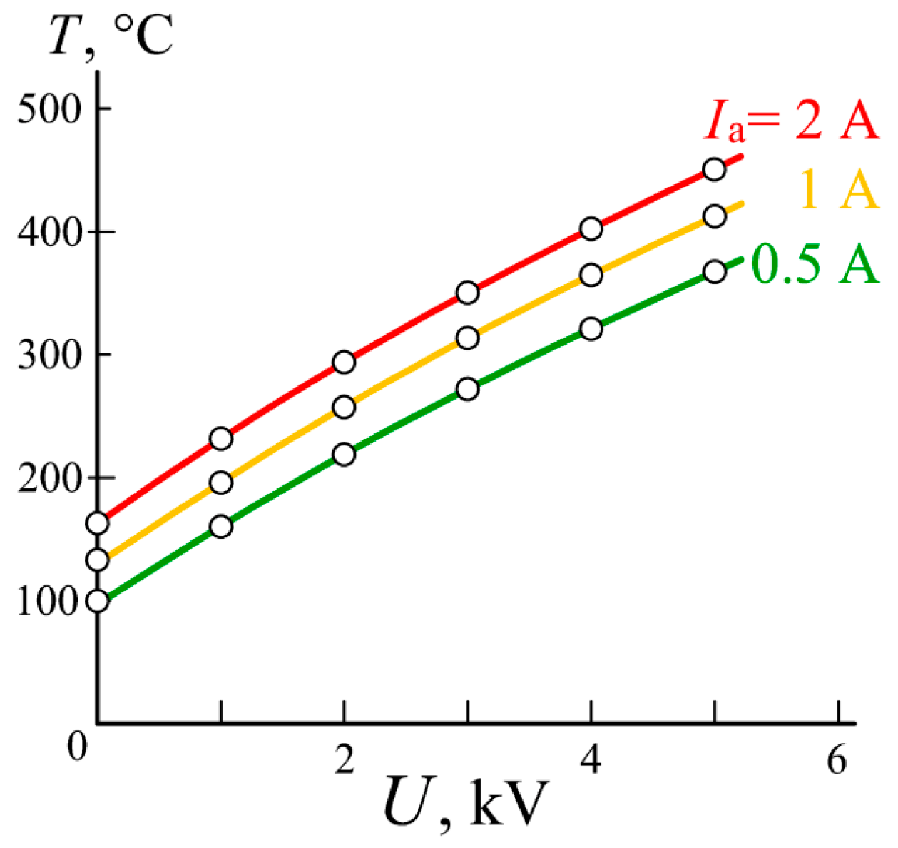
At the argon pressure p = 0.2 Pa, the width of both grid sheaths exceeds the charge exchange length λc by two times. Accelerated in the sheaths, the ion turns into the fast neutral atom and leaves the sheaths with energy ε corresponding to the potential difference between the plasma and the point, where the charge exchange collisions took place. Thus, the energy of fast atoms is distributed continuously from zero to e(U + Ud). In this way, a diverging beam of fast atoms bombarding the chamber and a beam converging on the surface of rotating reamers are formed. Bombardment by fast argon atoms results in the reamers heating and etching. Their temperature is controlled using a pyrometer (Figure 3). Figure 4 presents dependence on the grid bias voltage U of the reamer temperature T at the argon pressure p = 0.5 Pa and various discharge currents Ia in the anode circuit. Each measurement was carried out in 10 min after the change of the current Ia when the temperature of the rotating reamer was already established. Figure 4 shows that the temperature T grows with current Ia and voltage U reaching T = 450 °C at Ia = 2 A and U = 3 kV.
The reamer etching rate can be estimated by measuring the etching rate of the substrate positioned close to the lower reamer (Figure 2b). When p increases from 0.2 to 2 Pa, maximal energy of fast atoms is decreasing from 3 keV to 300 eV, their number grows by a factor of 10, hence, the neutral beam current rises.
Figure 5a presents a photograph of a 16-mm-diameter reamer made of high-speed steel HS6-5-2 with a 90 mm long working part. It was processed in glow discharge plasma at argon pressure p = 0.5 Pa, discharge current in the anode circuit Ia = 2A, and accelerating voltage between the chamber and the grid U ≈ 5 kV together with the second reamer fastened on the common rotating holder (Figure 1a). At these parameters the discharge voltage between the anode and the chamber amounts to Ud ≈ 230 V, the current in the grid circuit amounts to I = 0.85 A and the temperature of the reamer established in 10 min after application to the grid of bias voltage U = 5 kV amounts to 450 °C.
The holder and reamers are isolated from the chamber and their floating potential, which accelerates ions from the plasma, does not exceed 15 V. Hence, the contribution of the ions to the heating of the reamers is negligible.
The current density of argon ions on the tool cutting edge is about a hundred times higher than on the neighboring surface. However, their energy does not exceed 15 eV, which is less than the sputtering threshold, and for this reason, they cannot sputter and blunt cutting edges of the tools. On the contrary, the flow density of fast argon atoms arriving at the reamer from the grid (Figure 3) is distributed on its surface quite homogeneously. Sputtering by the fast atoms results in removal from the cutting edge and neighboring surface [45,46] of a layer with uniform thickness, which should result in the tool sharpening [47].
Figure 5b demonstrates profiles of the reamer cutting edges, their width w, and height h being measured in μm, prior to the processing (on the left) as well as after sharpening and nitriding (in the middle). Sharpening by fast argon atoms was carried out in an argon plasma at the above discharge parameters within 2 h. Then, the argon was replaced with nitrogen and the reamers stood within 1 h in nitrogen plasma at the above discharge parameters and a temperature of 450 °C stabilized by regulation of the grid voltage U. Figure 5b shows that processing of the reamers by fast argon and nitrogen atoms resulted in an appreciable decrease in the cutting edge radius from ~7 μm to ~2 μm and a flattening of its lateral sides. After the 3 h long processing, the mask was detached from the substrate fastened on the holder (Figure 2), and the height δ of the step between open and mask-covered surfaces of the substrate was measured. The measured value δ ~ 5.3 μm is close to the difference of the initial and the final radii.
The microhardness on the substrate surface, which was masked during the processing, amounts to 900 HV. This value slightly exceeds the microhardness of 860 HV measured before the processing. Microhardness of the surface exposed to the plasma and fast argon atoms grew up to 1300 HV, which is by about 1.5 times higher than the initial microhardness of 860 HV. As the reamer is made of the same material (high-speed steel HS6-5-2) we may assume that microhardness of the reamer surface also increased to ~1300 HV after the nitriding.
The same substrate made of HS6-5-2 was fastened close to another reamer, which after the identical sharpening and nitriding procedure was coated with titanium nitride. Before the coating synthesis, the targets of both magnetrons were connected to their 50 kHz power supply, the accelerating grid was using the switch (15) (Figure 1) disconnected from the DC power supply (16) and connected to the high-voltage pulse generator (17); the mixture of argon with nitrogen (15%) was admitted to the chamber and, at the gas pressure p = 0.5 Pa, the DC power supply 8 was switched on. After the chamber is filled with glow discharge plasma, high-voltage pulses are applied to the grid and the 50 kHz power supply is switched on.
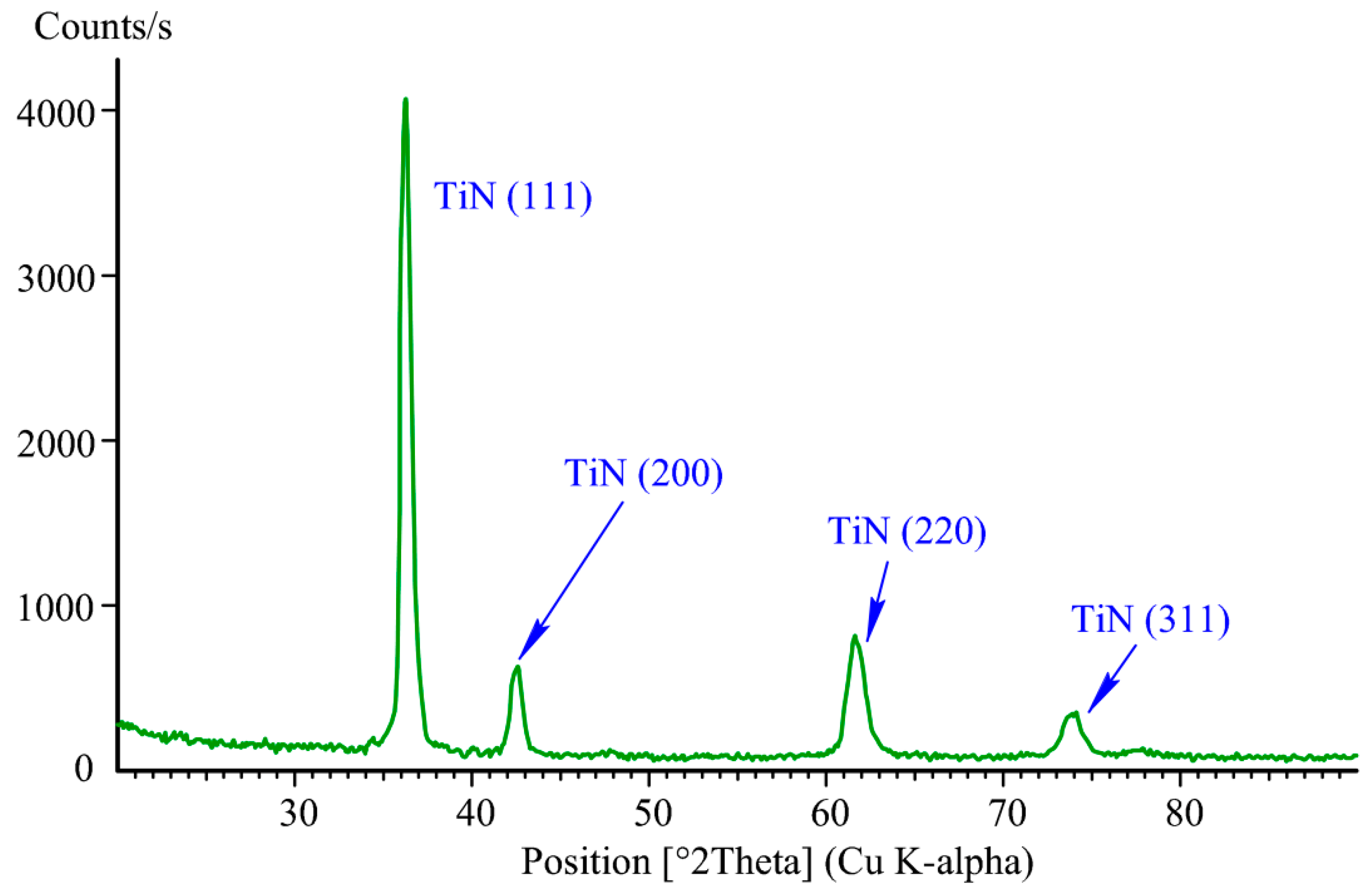
At a stabilized AC current of Im = 15 A in the circuit of magnetrons, stabilized DC current of Ia = 2 A in the anode circuit and 3 kV amplitude of 50 μs, and wide negative pulses applied to the reamers with a repetition rate of 50 Hz on the reamers and the substrate during 2 h, titanium nitride coatings were synthesized. The gold color of the coatings and the X-ray diffractogram for the coating deposited on the substrate (Figure 6) show that the coatings contain only one phase of TiN.
Figure 5b (on the right) demonstrates that the combined processing of the reamers, which includes sharpening, nitriding and coating deposition, resulted in the cutting edge radius decrease from ~7 μm to ~5 μm and flattening of its lateral sides.
The measured value of the step between the covered by the mask and coated surfaces of the substrate δ ~ 2.2 μm is close to the difference between the initial radius of the cutting edge R ~ 7 μm and its value R ~5 μm after the combined processing. Taking into account that in the previous experiment the height of the step between the mask-covered and nitrided surfaces of the former substrate was equal to δ ~ 5.3 μm, we may assume that the deposited coating thickness is approximately equal to 3 μm and the coating deposition rate amounts to 3 μm/2 h = 1.5 μm·h−1.
Microhardness of the coating synthesized on the substrate measured was equal to 2600 HV. For characterization of the coating adhesion, the first critical load, which results in the first cracks on the coating and appearance of acoustic emission, is equal to Lc1 = 22 N, and the second critical load leading to the coating destruction is equal to Lc2 =27 N. It means that adhesion is better than in the case of the conventional technology.
The formation of a transition nitrided layer on the surface of high-speed steel before coating minimizes the difference in the properties of the hard coating and high-speed steel. If the coating is applied to non-nitrided high-speed steel, then high stresses are formed at their boundary due to the difference in material properties, which can reduce the adhesion of coatings and accelerate their destruction. The formation of the nitrided layer on the surface of the high-speed tool, which has a higher hardness and heat resistance compared to high-speed steel, will increase the tool’s resistance to loads during the cutting process.
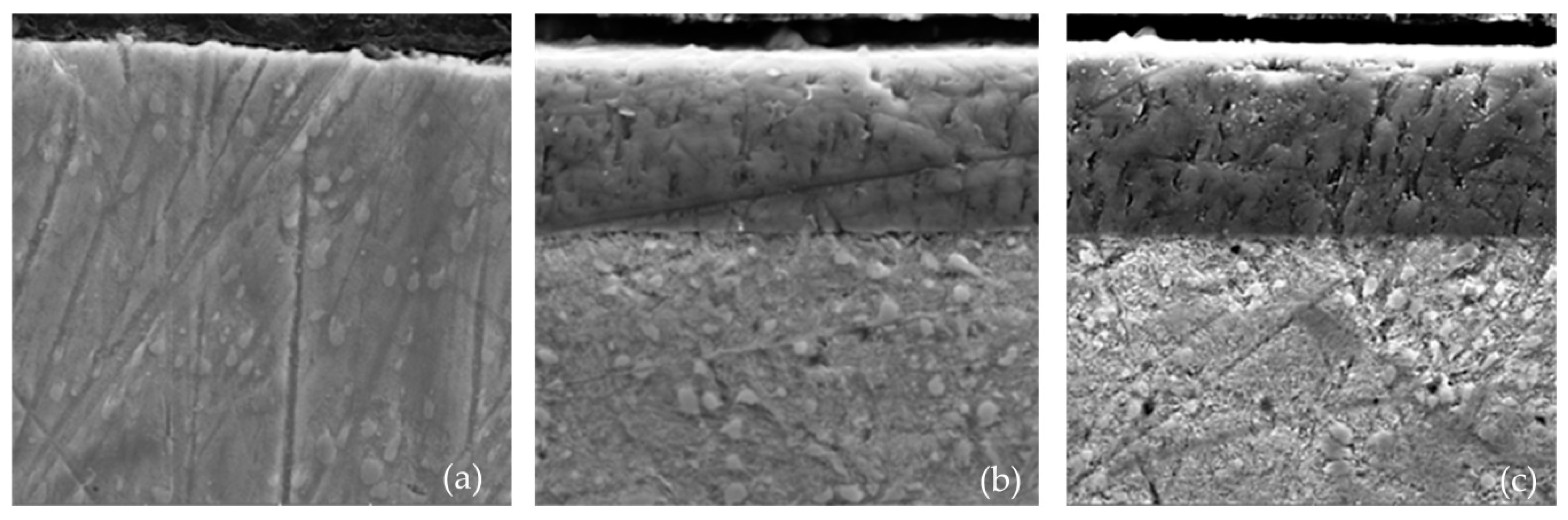
Figure 7 shows the results of the analysis of the surface layer of high-speed steel reamers with various surface treatments. In the presented scanning electron microscope (SEM) images, the sharp border of the transition from high-speed steel to the coating is visible. However, the boundary of the transition from high-speed steel to nitrided layer cannot be evaluated using SEM.
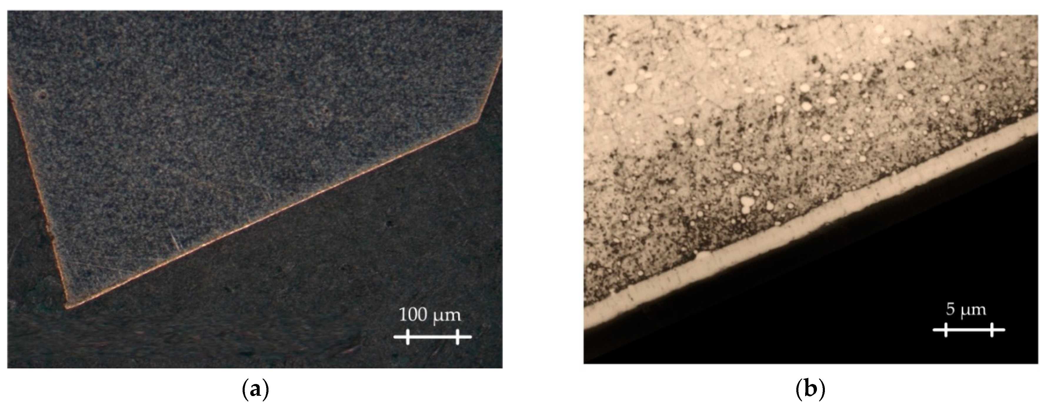
In the optical images presented in Figure 8, it can be seen that under the coating a nitrided layer is formed in the surface layer which turns smoothly into a high-speed substrate. It is evident that the nitrided layer provides a smoother transition of physical and mechanical properties from the core to the surface and vice versa.
It is well known that for tools made of high-speed, the main effect of the coating is to increase the hardness of the contact pads of the cutting tools and reduce the coefficient of friction with the material being processed, which significantly reduces the adhesive interaction between the contacting surfaces. Coatings transform the functional and physical parameters of the cutting process-chip formation, contact, and thermal processes, and, as a result, significantly reduce the wear rate of the cutting tool. Obviously, the changes also affect the roughness of the machined surface, which is a measure of the effectiveness of the cutting process during the finishing operations.
A comparative study of the surface roughness in the holes, machined by the basic tool prior to the strengthening of its surface and by the identical tool after strengthening, was carried out to assess the effectiveness of the developed technology of the combined strengthening of cutting tools. The tests were carried out when machining holes in blanks of structural steel 41Cr4 (TSK Kamenniy Poyas-NT, Nizhny Tagil, Russia) with the following cutting conditions: cutting speed 75 m·min−1, feed 0.15 mm·rev−1, cutting depth 0.05 mm. The tests were carried out without the use of any coolant.
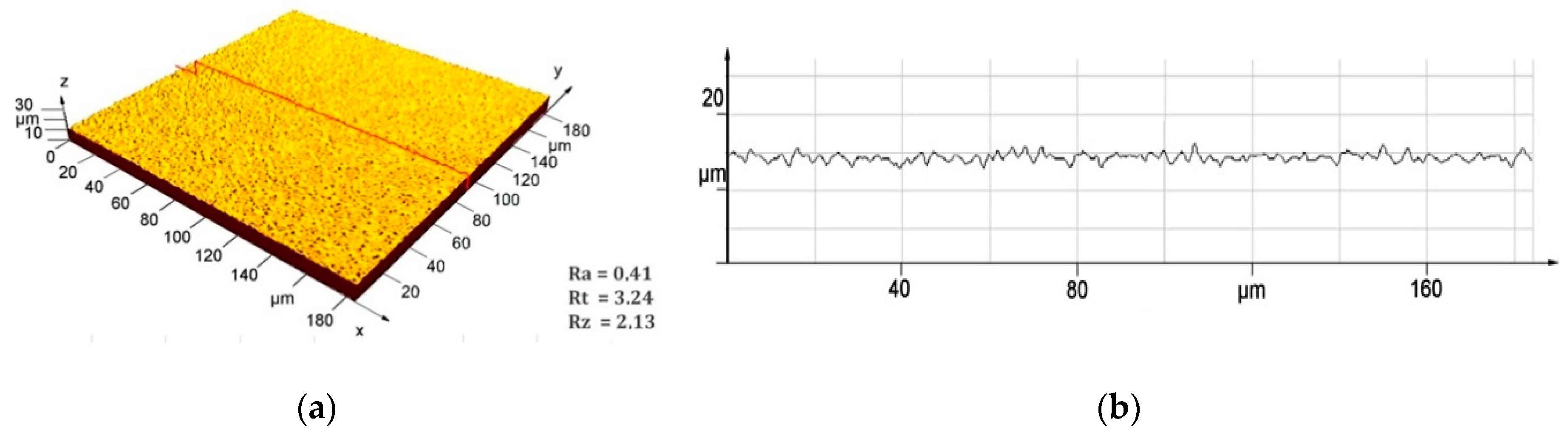
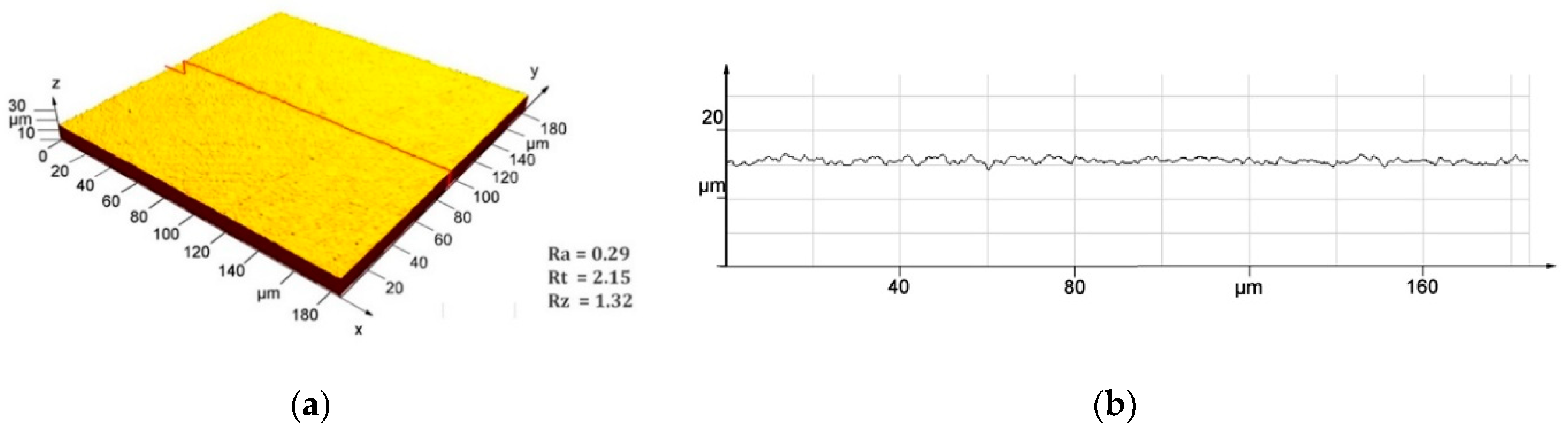
Figure 9 and Figure 10 shows the profilograms of the surface roughness of the holes in the blanks of steel 41Cr4, machined by the basic tool prior to combined processing of the tool surface and by the identical tool after the combined processing.
The presented experimental results show that the proposed technology of combined strengthening of the cutting tools provides a significantly higher quality of the machined hole surface. The reamer after the combined strengthening provides a reduction in the roughness of the machined hole in the Ra parameter by 1.4 times in comparison with an uncoated reamer, in the Rt parameter by 1.5 times and in the Rz parameter by 1.6 times.
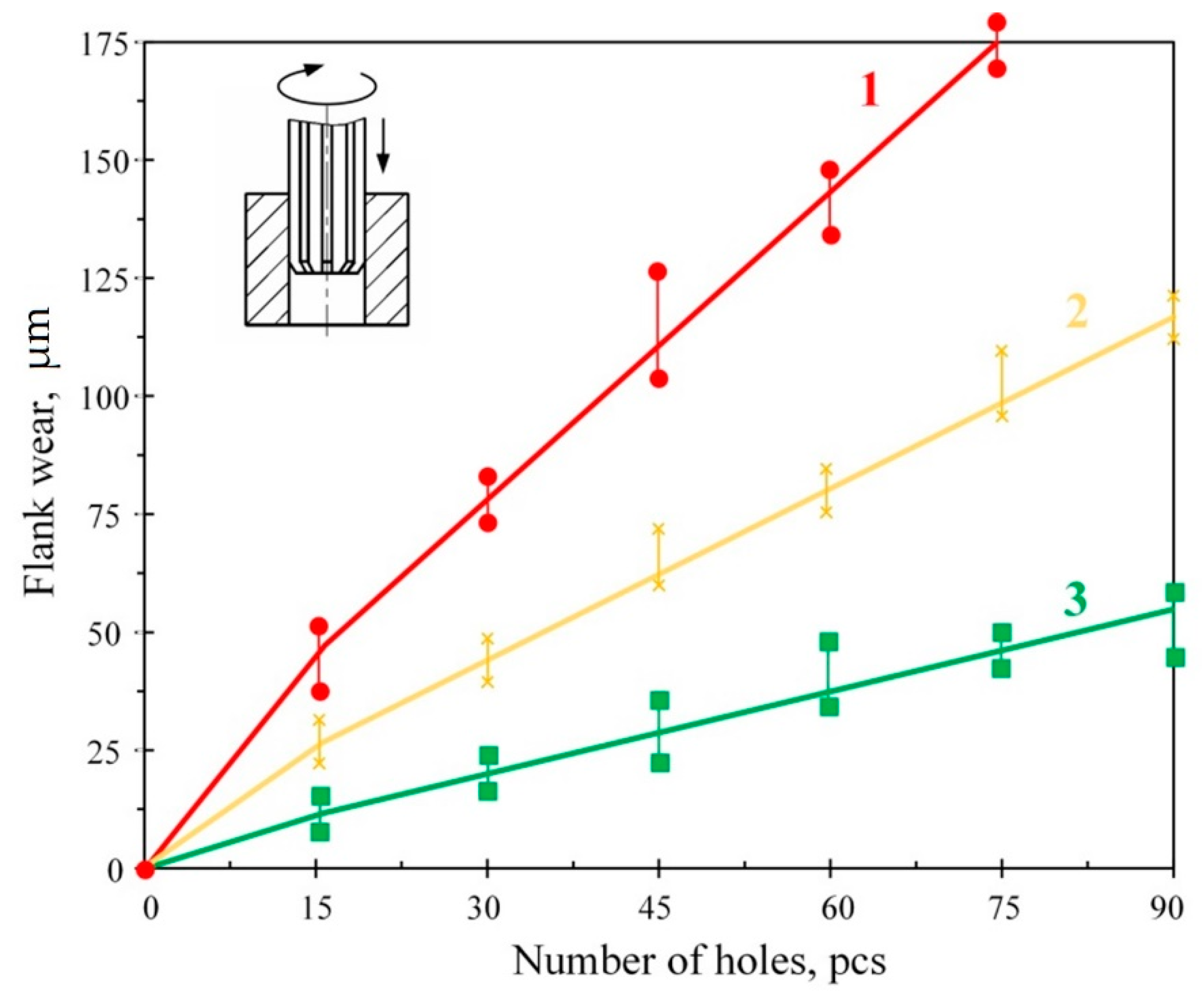
Following studies of the intensity of wear of the reamers with various types of surface treatment during the formation of holes in the blanks of 41Cr4 steel, it is possible to estimate the quantitative effect of combined surface strengthening. The criterion for the failure of reamers in the experiment was taken from the wear on the back surface, the limiting value of which was 150 μm. The experiments showed that even after reaching the specified value, the tool retains its operational condition. However, excess wear of 150 μm significantly increases the roughness of the machined surface of the part, which is unacceptable during finishing cutting operations or during machining of the parts with high precision for which reaming is widely used. The quantitative value of tool wear on the back surface was monitored with an optical microscope at the end of processing every 15 holes and recorded in the test report (90 holes were processed in total). To avoid mistakes, each experience was duplicated three times. Comparative tests were carried out on the following modes: cutting speed 75 m·min−1, feed 0.15 mm·rev−1, cutting depth 0.05 mm.
Figure 11 presents the results of tests where it is clear that the wear of the reamers without surface treatment reaches the limiting value (150 μm) after machining 63 holes. The wear of the coated tool after processing the specified number of holes was about 85 μm, and the after combined surface strengthening tool 40 μm. Thus, the proposed combined surface strengthening technology significantly (more than 3.7 times) increases the tool life in comparison to reamers without surface treatment. This effect is noticeably less for coated reamers: the tool life increased by 1.7 times only.
4. Discussion
The combined processing of cutting tools based on the vacuum arc, which includes the surface pre-nitriding and subsequent deposition of wear-resistant coatings [18,23,26], has two main drawbacks. The first is blunting of the tools’ cutting edges during the plasma immersion nitriding caused by the high current density of sputtering ions on the cutting edges. A second drawback is a significant number of comparatively soft metal droplets incorporated in very hard coatings.
The combined arc technology was modernized in [48] where the process chamber plays the role of an anode in the hollow cathode glow discharge. Inside a cylindrical hollow cathode mounted on the chamber is located a thermionic cathode made of tungsten wire. The minimal operating pressure in the chamber is equal to ~0.1 Pa and the discharge voltage amounts to ~30 V. The hollow cathode discharge with thermionic cathode was successfully used for the ion nitriding using high-current plasma immersion implantation of nitrogen ions. No metal droplets appear during the nitriding. Nevertheless, the same vacuum arc is used for the coating deposition and synthesized coatings contain metal droplets. Another serious drawback of the system described in [49] is a very short useful life of the tungsten thermionic cathodes, which does not exceed ~10 hours. In order to exclude the droplets, the combined processing should use magnetron sputtering [50,51] instead of vacuum arc evaporation. Instead of the hollow cathode with an inner thermionic cathode for the generation of homogeneous plasma inside the chamber, it is quite enough to use the latter itself as a hollow cathode (Figure 3).
Usually, the process chamber serves as an anode for the planar magnetrons mounted on its walls. In this case, the potential of the magnetron discharge plasma is close to the chamber potential. However, when the glow discharge between the chamber and disc anode 6 (Figure 1) is established, the potential of the magnetron discharge plasma rises to the potential of the glow discharge plasma of 300–500 V. The stabilized current in the magnetron target circuit is switched over from the chamber circuit to the disc anode [52], and the output voltage of the magnetron power supply can fall to zero. It means that the magnetron power supply is underloaded and used mainly for the current stabilization, At the same time, the power supply of the glow discharge is overloaded.
In order to control the glow discharge current and the magnetron discharge current independently two magnetrons should be used simultaneously. The connection of their targets to an AC 50-kHz power supply forms a dual magnetron sputtering system. When one of the targets acts as an anode its potential is close to that of the glow discharge plasma and the second target acts as a sputter cathode, which is negative to the plasma. In half a period (10 μs) the targets change their roles. In any case, the number of magnetron targets should be even and twice as large as the number of AC power supplies.
Simultaneous operation of the glow discharge and the dual magnetron sputtering system substantially enlarges capabilities of the glow discharge with electrostatic confinement of electrons in a process vacuum chamber. It enables a combined ion-plasma processing of various products including sharpening of cutting tools, strengthening of their surface using nitriding, and deposition of wear-resistant coatings.
Immersion in the homogeneous glow discharge plasma of a curved grid and application to the grid of a negative bias voltage allows production of fast atom beams concentrated on the tool surface. At a continuous bias voltage, sharpening of the cutting edges can be carried out in argon and nitriding of the tool surface in nitrogen. Using pulsed beams of fast atoms synthesis of the wear-resistant coating can be carried out in the mixture of argon and nitrogen. An adequate microhardness and quite good adhesion of the deposited coatings are due to bombardment by fast atoms. At the substrate rotating speed of 24 rpm and the coating deposition rate of 1.5 μm·h−1 (or 0.4 nm·s−1), depth ~10 nm of 3 keV argon atoms penetration into the substrate exceeds the 0.5 nm thick coating layer synthesized on the substrate within 1.25 s (half of the revolution period). It means that in the second half-period the neutral argon atoms with the energy of 3 keV can mix atoms of the synthesized coating layer and atoms of the substrate. The mixing raises the interface width, thus improving the coating adhesion. If instead, the pulsed beam is used as a continuous beam of fast gas atoms, which sputter all deposited metal atoms, no coating is synthesized.
During discussion of the results of operational tests with various types of surface treatment, multiple increases in the dimensional resistance of the tool after combined surface strengthening (in 3.7 times) and a less significant increase in the resistance of the coated tool (in 1.7 times) should be mentioned. It can be assumed that this is due to the fact that in the process of abrasion of the coating, the friction conditions on the back surface of the non-nitrided tool approach those that are characteristic of a high-speed tool without coating. Hence, the amount of heat released increases and the temperature near the back surface increases, which contributes to an increase in wear rate. The slow development of wear of the tool after combined surface strengthening can be explained by the fact that the nitrided layer formed under the coating has a higher hardness and heat resistance than high-speed steel. Even after the abrasion of a thin coating during the cutting process, the nitrided layer continues undertaking its functional purpose and helps to reduce the wear rate of the working surfaces of the reamer.
5. Conclusions
- The AC dual magnetron sputtering systems and the DC glow discharge with electrostatic confinement of electrons in a process vacuum chamber are compatible, and it enables combined processing of cutting tools including sharpening of the cutting edges, surface strengthening by nitriding, and subsequent synthesis of wear-resistant coatings.
- A negatively biased curved grid immersed in the glow discharge plasma allows production of a fast atom beam, which heats and etches the tool surface. At a continuous bias voltage, sharpening of the cutting edges can be carried out in argon and nitriding of the tool surface in nitrogen. Pulsed beams of fast atoms ensure synthesis on the strengthened tool surface in a mixture of argon and nitrogen of magnetron-sputtered hard coatings remarkable for high adhesion. The combined processing allows not only strengthening of the tools but also reduction of their cutting edge radius, thus enabling the performance improvement and an increase in the useful lifetime of cutting tools for finishing and microtools.
- Improvement of the coating adhesion is due to mixing atoms of the tool surface layer and atoms of the synthesized coating layer in the very beginning of the coating deposition, which leads to growth of the interface width.
- The proposed combined surface strengthening technology makes possible a reduction in the roughness of the machined hole in the Ra parameter to 0.2 μm, ensuring a significantly higher surface quality of the machined hole in comparison to reamers without surface treatment. Such a high quality of the surface layer allows consideration of the processing by the reamers after the combined surface strengthening as an alternative to grinding.
- The multiple increases in the dimensional stability of reamers after combined surface strengthening shown during the study provides significantly more economical use of tool materials and a reduction in production costs. An important advantage in the production of such a tool is the ability to assign significantly higher cutting speeds than for a traditional tool made of high-speed steels, which will increase the productivity of the reaming.
6. Patents
- Metel, A.S.; Grigoriev, S.N.; Melnik, Y.A.; Volosova, M.A. Device for the synthesis of coatings. RU 2657896, 18 June 2018.
- Bolbukov, V.P.; Volosova, M.A.; Melnik, Y.A.; Metel, A.S.; Grigoriev, S.N. Device for the synthesis of coatings. RU 2531373, 20 October 2014.
- Metel, A.S.; Grigoriev, S.N.; Volosova, M.A.; Melnik, Y.A.; Bolbukov, V.P.; Chelapkin, D.G.; Beletsky, V.E.; Kireev, V.Y.; Knyazev, S.A. Device for the deposition of metal films. RU 2510984, 10 April 2014.
- Grigoriev, S.N.; Metel, A.S.; Melnik, Y.A.; Panin, V.V. Source of fast neutral atoms. RU 2373603, 20 November 2009.
Author Contributions
Conceptualization, S.N.G. and A.S.M.; Methodology, S.N.G., Y.A.M. and M.N.V.; Software, Y.A.M.; Validation, Y.A.M. and M.N.V.; Formal Analysis, A.S.M.; Investigation, A.S.M.; Resources, S.N.G. and M.N.V.; Data Curation, Y.A.M.; Writing-Original Draft Preparation, A.S.M. and Y.A.M.; Writing-Review and Editing, A.S.M. and M.N.V.; Visualization, Y.A.M. and M.N.V.; Supervision, S.N.G.; Project Administration, S.N.G. and M.N.V.; Funding Acquisition, S.N.G. and A.S.M.
Funding
This research was funded by the Ministry of Education and Science of Russian Federation, No. 9.7886.2017/6.7.
Acknowledgments
The work is carried out using the equipment of the Center of collective use of MSUT Stankin. The Department of High-efficiency Machining Technologies of MSUT Stankin provided samples of material and tools for research.
Conflicts of Interest
The authors declare no conflict of interest.
References
- Anders, A. Cathodic Arcs: From Fractal Spots to Energetic Condensation; Springer: Berlin, Germany, 2008; pp. 21–23. ISBN 978-0-387-79108-1. [Google Scholar]
- Beilis, I.; Koulik, Y.; Yankelevich, Y.; Arbilly, D.; Boxman, R.L. Thin-film deposition with refractory materials using a vacuum arc. IEEE Trans. Plasma Sci. 2015, 43, 2323–2328. [Google Scholar] [CrossRef]
- Boxman, R.L.; Zhitomirsky, V.N. Vacuum arc deposition devices. Rev. Sci. Instrum. 2006, 77, 021101. [Google Scholar] [CrossRef]
- Rincón-Llorente, G.; Heras, I.; Guillén Rodríguez, E.; Schumann, E.; Krause, M.; Escobar-Galindo, R. On the Effect of Thin Film Growth Mechanisms on the Specular Reflectance of Aluminium Thin Films Deposited via Filtered Cathodic Vacuum Arc. Coatings 2018, 8, 321. [Google Scholar] [CrossRef]
- Smyrnova, K.V.; Pogrebnjak, A.D.; Beresnev, V.M.; Litovchenko, S.V.; Borba-Pogrebnjak, S.O.; Manokhin, A.S.; Klimenko, S.A.; Zhollybekov, B.; KupchishinYa, A.I.; Kravchenko, O.; et al. Microstructure and Physical-Mechanical Properties of (TiAlSiY)N Nanostructured Coatings Under Different Energy Conditions. Met. Mater. Int. 2018, 24, 1024–1035. [Google Scholar] [CrossRef]
- Kuang, H.; Tan, D.; He, W.; Yi, Z.; Zou, Z.; Wang, X. Oxidation Behavior of Multilayer Hard Coatings (TiCN/Al2O3/TiN) in Process of Recycling Coated Multicomponent Hardmetal Scrap. Materials 2018, 11, 1796. [Google Scholar] [CrossRef] [PubMed]
- Wang, Y.; Lin, Y. Study on the Performance of Nano-Titanium Nitride-Coated Stainless Steel Electrodes in Electro-Fenton Systems. Nanomaterials 2018, 8, 494. [Google Scholar] [CrossRef] [PubMed]
- Avelar-Batista, J.C.; Spain, E.; Housden, J.; Matthews, A.; Fuentes, G.G. Plasma nitriding of Ti6Al4V alloy and A1S1 M2 steel substrates using DC glow discharge under a triode configuration. Surf. Coat. Technol. 2005, 200, 1954–1961. [Google Scholar] [CrossRef]
- Ivanova, A.A.; Surmeneva, M.A.; Shugurov, V.V.; Koval, N.N.; Shulepov, I.A.; Surmenev, R.A. Physico-mechanical properties of Ti-Zr coatings fabricated via ion assisted arc-plasma deposition. Vacuum 2018, 14, 129–133. [Google Scholar] [CrossRef]
- Kravchenko, Y.O.; Coy, L.E.; Peplinska, B.; Iatsunskyi, I.; Załęski, K.; Kempiǹski, M.; Kempiǹski, M.; Beresnev, V.M.; Konarski, P.; Jurga, S.; et al. Nano-multilayered coatings of (TiAlSiY)N/MeN (Me=Mo, Cr and Zr): Influence of composition of the alternating layer on their structural and mechanical properties. J. Alloys Compd. 2018, 767, 483–495. [Google Scholar] [CrossRef]
- Takesue, S.; Kikuchi, S.; Akebono, H.; Komotori, J. Effect of the Nitrogen Diffusion Layer Formed by Gas Blow Induction Heating Nitriding on Wear Resistance and Fatigue Properties of Titanium Alloy. Proceedings 2018, 2, 409. [Google Scholar] [CrossRef]
- Aizawa, T.; Wasa, L. Low Temperature Plasma Nitriding of Inner Surfaces in Stainless Steel Mini-/Micro-Pipes and Nozzles. Micromachines 2017, 8, 157. [Google Scholar] [CrossRef]
- Anders, A. Tutorial: Reactive high power impulse magnetron sputtering. J. Appl. Phys. 2017, 121, 171101. [Google Scholar] [CrossRef]
- Horikoshi, S.; Mochizuki, J.; Oya, Y.; Chikada, T. Deuterium permeation and retention behaviors in erbium oxide-iron multilayer coatings. Fusion. Eng. Des. 2017, 124, 1086–1090. [Google Scholar] [CrossRef]
- Nakao, S.; Kimura, T.; Suyama, T.; Azuma, K. Conductive diamond-like carbon films prepared by high power pulsed magnetron sputtering with bipolar type plasma based ion implantation system. Diam. Relat. Mater. 2017, 77, 122–130. [Google Scholar] [CrossRef]
- Musil, J.; Lestina, J.; Vlček, J.; Tölg, T. Pulsed DC magnetron discharge for high-rate sputtering of thin films. J. Vac. Sci. Technol. A 2001, 19, 420–424. [Google Scholar] [CrossRef]
- Musil, J.; Rajsky, A.; Bell, A.J.; Matouš, J.; Čepera, M.; Zeman, J. High-rate magnetron sputtering. J. Vac. Sci. Technol. A 1996, 14, 2187–2191. [Google Scholar] [CrossRef]
- Grigoriev, S.N.; Metel, A.S.; Volosova, M.A.; Melnik, Y. Improvement of Thin Film Adhesion Due to Bombardment by Fast Argon Atoms. Coatings 2018, 8, 303. [Google Scholar] [CrossRef]
- Grigoriev, S.N.; Melnik, Yu.A.; Metel, A.S.; Panin, V.V.; Prudnikov, V.V. A compact vapor source of conductive target material sputtered by 3-keV ions at 0.05-Pa pressure. Instrum. Exp. Tech. 2009, 52, 731–737. [Google Scholar] [CrossRef]
- Sangregorio, M.; Xie, K.; Wang, N.; Guo, N.; Zhang, Z. Ion engine grids: Function, main parameters, issues, configurations, geometries, materials and fabrication methods. Chin. J. Aeronaut. 2018, 31, 1635–1649. [Google Scholar] [CrossRef]
- Kostrin, D.K.; Lisenkov, A.A. Plasmachemical synthesis of coatings using a vacuum arc discharge Deposition of a coating on the inner surface of a cylindrical cavity. Vak. Forsch. Prax. 2017, 29, 35–39. [Google Scholar] [CrossRef]
- Schanin, P.M.; Koval, N.N.; Akhmadeev, Y.K. Generation of Gas Discharge Plasma by an Arc Source with a Cold Hollow Cathode. Instrum. Exp. Tech. 2005, 48, 328. [Google Scholar] [CrossRef]
- Grigoriev, S.; Metel, A. Plasma- and Beam-Assisted Deposition Methods; Voevodin, A.A., Shtansky, D.V., Levashov, E.A., Moore, J.J., Eds.; Springer: Berlin, Germany, 2004; pp. 147–154. ISBN 9781402022227 (online). ISBN 9781402022203 (print). [Google Scholar]
- Metel, A.; Bolbukov, V.; Volosova, M.; Grigoriev, S.; Melnik, Y. Source of metal atoms and fast gas molecules for coating deposition on complex shaped dielectric products. Surf. Coat. Technol. 2013, 225, 34–39. [Google Scholar] [CrossRef]
- Nowakowska-Langier, K.; Chodun, R.; Zdunek, K.; Okrasa, S.; Kwiatkowski, R.; Malinowski, K.; Skladnik-Sadowska, E.; Sadowski, M.J. OES studies of plasmoids distribution during the coating deposition with the use of the Impulse Plasma Deposition method controlled by the gas injection. Vacuum 2016, 128, 259–264. [Google Scholar] [CrossRef]
- Baba, K.; Hatada, R.; Flege, S.; Ensinger, W. Preparation and Properties of Ag-Containing Diamond-Like Carbon Films by Magnetron Plasma Source Ion Implantation. Adv. Mater. Sci. Eng. 2012, 536853. [Google Scholar] [CrossRef]
- Grigoriev, S.N.; Melnik, Yu. A.; Metel, A.S.; Volosova, M.A. Focused beams of fast neutral atoms in glow discharge plasma. J. Appl. Phys. 2017, 121, 223302. [Google Scholar] [CrossRef]
- Mills, R.L.; Zhao, G.; Akhtar, K.; Chang, Z.; He, J.; Lu, Y.; Good, W.; Chu, G.; Dhandapani, B. Commercializable power source from forming new states of hydrogen. Int. J. Hydrogen Energy 2009, 34, 573–614. [Google Scholar] [CrossRef]
- Goncic, B.; Popovic, N.; Bogdanov, Z.; Zec, S.; Zlatanovic, M. Low-energy broad-beam sputter deposition of TiNx thin films. Mater. Sci. Forum 2003, 413, 159–164. [Google Scholar] [CrossRef]
- Ou, Y.X.; Chen, H.; Li, Z.Y.; Lin, J.; Pan, W.; Lei, M.K. Microstructure and tribological behavior of TiAlSiN coatings deposited by deep oscillation magnetron sputtering. J. Am. Ceram. Soc. 2018, 101, 5166–5176. [Google Scholar] [CrossRef]
- Ghobadi, N.; Ganji, M.; Luna, C.; Arman, A.; Ahmadpourian, A. Effects of substrate temperature on the properties of sputtered TiN thin films. J. Mater. Sci. Mater. Electron. 2016, 27, 2800–2808. [Google Scholar] [CrossRef]
- Talu, S.; Stach, S.; Valedbagi, S.; Bavadi, R.; Elahi, S.M.; Ţălu, M. Multifractal characteristics of titanium nitride thin films. Mater. Sci. Pol. 2015, 33, 541–548. [Google Scholar] [CrossRef] [Green Version]
- Nose, M.; Nagae, T.; Yokota, M.; Zhou, M.; Saji, S.; Nakada, M. Electrical resistivity and luminous reflectance of TiN films prepared by DC reactive sputtering. J. Jpn. Inst. Met. 1999, 63, 1277–1282. [Google Scholar] [CrossRef]
- Changjie, F.; En, C.; Mingsheng, L.; Namei, W. Effects of Cu Content on Microstructure and High-Temperature Oxidation Behavior of Ti-Al-Si-Cu-N Nanocomposite Films. Rare Met. Mater. Eng. 2017, 46, 627–633. [Google Scholar] [CrossRef]
- Ruset, C.; Grigore, E. The influence of ion implantation on the properties of titanium nitride layer deposited by magnetron sputtering. Surf. Coat. Technol. 2002, 156, 159–161. [Google Scholar] [CrossRef]
- Ruset, C.; Grigore, E.; Collins, G.A.; Short, K.T.; Rossi, F.; Gibson, N.; Dong, H.; Bell, T. Characteristics of the Ti2N layer produced by an ion-assisted deposition method. Surf. Coat. Technol. 2003, 174, 698–703. [Google Scholar] [CrossRef]
- Grigore, E.; Ruset, C.; Short, K.T.; Hoeft, D.; Dong, H.; Li, X.Y.; Bell, T. In situ investigation of the internal stress within the nc-Ti2N/nc-TiN nanocomposite coatings produced by a combined magnetron sputtering and ion implantation method. Surf. Coat. Technol. 2005, 200, 744–747. [Google Scholar] [CrossRef]
- Kolobov, V.I.; Metel, A.S. Glow discharges with electrostatic confinement of fast electrons. J. Phys. D Appl. Phys. 2015, 48, 233001. [Google Scholar] [CrossRef]
- Metel, A.S. Effect of ionization in the cathode layer on the characteristics of a Penning discharge. I. Hollow cathode discharge. Sov. Phys. Tech. Phys. 1985, 30, 1133–1136. [Google Scholar]
- Raizer, Y.P. Gas Discharge Physics; Springer: Berlin, Germany, 2001; pp. 321–323. ISBN 978-3642647604. [Google Scholar]
- Liu, K.; Lei, J.; Zheng, Z.; Zhu, Z.; Liu, S. The hydrophilicity improvement of polytetrafluoroethylene by Ar plasma jet: The relationship of hydrophilicity, ambient humidity and plasma parameters. Appl. Surf. Sci. 2018, 458, 183–190. [Google Scholar] [CrossRef]
- Hechelef, B.; Bouchikhi, A. Identification of the normal and abnormal glow discharge modes in a neon-xenon gas mixture at low pressure. Plasma Sci. Technol. 2018, 20, 115401. [Google Scholar] [CrossRef]
- Phelps, A.V. Cross sections and swarm coefficients for nitrogen ions and neutrals in N2 and argon ions and neutrals in Ar for energies from 0.1 eV to 10 keV. J. Phys. Chem. Ref. Data 1991, 20, 557–573. [Google Scholar] [CrossRef]
- Metel, A.S.; Grigoriev, S.N.; Melnik, Yu.A.; Bolbukov, V.P. Characteristics of a fast neutral atom source with electrons injected into the source through its emissive grid from the vacuum chamber. Instrum. Exp. Tech. 2012, 55, 288–293. [Google Scholar] [CrossRef]
- Pan, C.; Li, Q.; Hu, K.; Jiao, Y.; Song, Y. Study on Surface Roughness of Gcr15 Machined by Micro-Texture PCBN Tools. Machines 2018, 6, 42. [Google Scholar] [CrossRef]
- Felhő, C.; Kundrák, J. Effects of Setting Errors (Insert Run-Outs) on Surface Roughness in Face Milling When Using Circular Inserts. Machines 2018, 6, 14. [Google Scholar] [CrossRef]
- Metel, A.; Grigoriev, S.; Melnik, Yu.; Panin, V.; Prudnikov, V. Cutting tools nitriding in the plasma produced by a fast neutral molecule beam. Jap. J. Appl. Phys. 2011, 50, 08JG04. [Google Scholar] [CrossRef]
- Koval, N.N.; Ryabchikov, A.I.; Sivin, D.O.; Lopatin, I.V.; Krysina, O.V.; Akhmadeev, Y.H.; Ignatov, D.Y. Low-energy high-current plasma immersion implantation of nitrogen ions in plasma of non-self-sustained arc discharge with thermionic and hollow cathodes. Surf. Coat. Technol. 2018, 340, 152–158. [Google Scholar] [CrossRef]
- Anders, A.; Yang, Y.C. Direct observation of spoke evolution in magnetron sputtering. Appl. Phys. Let. 2017, 111, 064103. [Google Scholar] [CrossRef] [Green Version]
- Anders, A.; Yang, Y.C. Plasma studies of a linear magnetron operating in the range from DC to HiPIMS. J. Appl. Phys. 2018, 123, 043302. [Google Scholar] [CrossRef]
- Musil, J.; Jaros, M.; Kos, S.; Čerstvý, R.; Haviar, S. Hard TiN2 dinitride films prepared by magnetron sputtering. J. Vac. Sci. Technol. 2018, 36, 040602. [Google Scholar] [CrossRef]
- Sasaki, K.; Koyama, H. Magnetron sputtering of liquid tin: Comparison with solid tin. Appl. Phys. Express 2018, 11, 036201. [Google Scholar] [CrossRef]
Figure 1.
A three-dimensional model of the process vacuum chamber: (a) a view with an open door; (b) a view with an accelerating grid.
Figure 1.
A three-dimensional model of the process vacuum chamber: (a) a view with an open door; (b) a view with an accelerating grid.

Figure 2.
Two parts of the reamer holder: (a) an upper part; (b) a lower part.

Figure 3.
Schematic diagram of the experimental setup.

Figure 4.
Dependence of the reamer temperature T on the grid bias voltage U at the argon pressure p = 0.5 Pa and various values of the discharge current Ia.
Figure 4.
Dependence of the reamer temperature T on the grid bias voltage U at the argon pressure p = 0.5 Pa and various values of the discharge current Ia.

Figure 5.
A 16-mm-diameter reamer made of high-speed steel HS6-5-2: (a) a photograph of the reamer; (b) scanning electron microscope (SEM) image (9×) of reamer cross-section; (c) profiles of the reamer cutting edges before processing (on the left), after sharpening and nitriding (in the middle) and after synthesis on the nitrided surface of the 3 μm thick TiN coating (on the right).

Figure 6.
The grazing incidence X-ray diffraction pattern for the coating deposited on the substrate.
Figure 6.
The grazing incidence X-ray diffraction pattern for the coating deposited on the substrate.

Figure 7.
SEM images (×7000) of the microstructure of the reamers made of high-speed steel: (a) without coating; (b) TiN coated; (c) after combined surface strengthening.
Figure 7.
SEM images (×7000) of the microstructure of the reamers made of high-speed steel: (a) without coating; (b) TiN coated; (c) after combined surface strengthening.

Figure 8.
Optical images of a high-speed steel reamer after combined surface strengthening: (a) a general view of a reamer tooth; (b) microstructure of the surface layer of the reamer tooth.
Figure 8.
Optical images of a high-speed steel reamer after combined surface strengthening: (a) a general view of a reamer tooth; (b) microstructure of the surface layer of the reamer tooth.

Figure 9.
Profilograms of the hole surface machined by a reamer without coating: (a) 3D-profilogram of the hole surface; (b) 2D-profilogram of the hole surface.
Figure 9.
Profilograms of the hole surface machined by a reamer without coating: (a) 3D-profilogram of the hole surface; (b) 2D-profilogram of the hole surface.

Figure 10.
Profilograms of the hole surface machined by a reamer after combined surface strengthening: (a) 3D-profilogram of the hole surface; (b) 2D-profilogram of the hole surface.
Figure 10.
Profilograms of the hole surface machined by a reamer after combined surface strengthening: (a) 3D-profilogram of the hole surface; (b) 2D-profilogram of the hole surface.

Figure 11.
The dependence of wear on the back surface with different surface treatment on the number of machined holes in the blanks made of 41Cr4 steel: (1) uncoated; (2) TiN coated; (3) after combined surface strengthening.
Figure 11.
The dependence of wear on the back surface with different surface treatment on the number of machined holes in the blanks made of 41Cr4 steel: (1) uncoated; (2) TiN coated; (3) after combined surface strengthening.

© 2018 by the authors. Licensee MDPI, Basel, Switzerland. This article is an open access article distributed under the terms and conditions of the Creative Commons Attribution (CC BY) license (http://creativecommons.org/licenses/by/4.0/).
Share and Cite
MDPI and ACS Style
Grigoriev, S.N.; Metel, A.S.; Melnik, Y.A.; Volosova, M.A. Equipment and Technology for Combined Ion–Plasma Strengthening of Cutting Tools. Machines 2018, 6, 58. https://doi.org/10.3390/machines6040058
AMA Style
Grigoriev SN, Metel AS, Melnik YA, Volosova MA. Equipment and Technology for Combined Ion–Plasma Strengthening of Cutting Tools. Machines. 2018; 6(4):58. https://doi.org/10.3390/machines6040058
Chicago/Turabian StyleGrigoriev, Sergey N., Alexander S. Metel, Yury A. Melnik, and Marina A. Volosova. 2018. "Equipment and Technology for Combined Ion–Plasma Strengthening of Cutting Tools" Machines 6, no. 4: 58. https://doi.org/10.3390/machines6040058
Note that from the first issue of 2016, this journal uses article numbers instead of page numbers. See further details here.