Article

Active Assistive Design and Multiaxis Self-Tuning Control of a Novel Lower Limb Rehabilitation Exoskeleton

1
Department of Mechanical and Electro-Mechanical Engineering, National Sun Yat-Sen University, Kaohsiung 804, Taiwan
2
Department of Mechanical Engineering, National Taiwan University, Taipei 106, Taiwan
3
GreenEpoxy Technology Corporation, Kaohsiung 824, Taiwan
4
Department of Physical Medicine and Rehabilitation, Kaohsiung Veterans General Hospital, Kaohsiung 813, Taiwan
*
Authors to whom correspondence should be addressed.
These authors contributed equally to this work.
Machines 2022, 10(5), 318; https://doi.org/10.3390/machines10050318
Submission received: 26 March 2022 / Revised: 14 April 2022 / Accepted: 26 April 2022 / Published: 28 April 2022
(This article belongs to the Topic Motion Planning and Control for Robotics)

Abstract

:
This paper presented the mechanical design and control of a lower limb rehabilitation exoskeleton named “the second lower limb rehabilitation exoskeleton (LLRE-II)”. The exoskeleton with a lightweight mechanism comprises a 16-cm stepless adjustable thigh and calf rod. The LLRE-II weighs less than 16 kg and has four degrees of freedom on each leg, including the waist, hip, knee, and ankle, which ensures fitted wear and comfort. Motors and harmonic drives were installed on the joints of the hip and knee to operate the exoskeleton. Meanwhile, master and slave motor controllers were programmed using a Texas Instruments microcontroller (TMS320F28069) for the walking gait commands and evaluation boards (TMS320F28069/DRV8301) of the joints. A self-tuning multiaxis control system was developed, and the performance of the controller was investigated through experiments. The experimental results showed that the mechanical design and control system exhibit adequate performance. Trajectory tracking errors were eliminated, and the root mean square errors reduced from 6.45 to 1.22 and from 4.15 to 3.09 for the hip and knee, respectively.

1. Introduction

The mobility of the aging population is restricted owing to sarcopenia or physical disabilities. An exoskeleton is a wearable orthosis that provides human body assistance via integrated robotic mechanisms. Exoskeletons started being investigated many decades ago and have garnered significant interest owing to the current development of the aging society [1,2,3,4,5].
In the 1960s, the exoskeleton “Hardiman”, which is powered by electrical motors and a master–slave control system, was the first exoskeleton to be developed by General Electric Company; however, it failed to operate as intended owing to its complex and heavy structure [6]. Recently, researchers at Tsukuba University developed a hybrid assistive limb (HAL) for patients with lower-limb illnesses. The HAL comprises posture and power-assist control and is powered by motors and a hybrid controller. Electromyography (EMG) sensors were installed on the HAL to capture foot reaction forces and detect the walking intention of the wearer [7]. Meanwhile, the Berkeley lower-extremity exoskeleton is an anthropomorphic model comprising seven degrees of freedom (DOFs) per leg, four of which are powered by linear hydraulic actuators. The exoskeleton enables the wearer to carry significant loads with minimal effort over different terrains. Furthermore, it allows various payloads to be mounted on a backpack-like frame [8,9].
More recently, the Harbin Institute of Technology proposed a lower-limb exoskeleton (LLE) to assist wearers in different situations. They used fuzzy logic to detect gait phases and a hybrid control strategy to improve stability and tracking precision [10]. At the Hefei University of Technology, a two-DOF LLE robot system with uncertainties and external disturbances was developed by optimizing the adaptive robust control and control gain parameters [11]. In another study, a lower-limb empowered rehabilitation named “moving up” was proposed. An adaptive fuzzy control scheme was introduced to achieve stable operation control for the assistant rehabilitation system, and the results showed that the system satisfied the requirements of the elderly [12]. For servo drive control, the dependence of the maximum bandwidths of servo drives on the sampling strategy and control design parameters was presented in [13]. An online auto-tuning method for the servo control loops of servo drives was proposed, where controller gains are tuned automatically by searching for the optimal bandwidth and identifying inertia [14]. Meanwhile, a multi-loop modulation method for servo drives applied to LLEs was proposed in another study [15], which resulted in improved system response and stability. Other controller developments, such as an improved particle swarm optimization adaptive PID controller, were proposed [16], based on which the human–exoskeleton system can operate effectively for trajectory tracking. An adaptive adjustment strategy was developed for a single-legged exoskeleton robot [17]. The algorithm for motions uses the walking data of the user to predict the joint angle data of the exoskeleton and achieve adaptive adjustment. A precision interaction force controller was proposed for a hydraulic leg exoskeleton [18]. Furthermore, a gain-tuning method was proposed to facilitate controller gain selection.
Previous studies typically focused on the mechanisms, medical applications, commercial equipment, and control methods of rehabilitation LLEs [19,20,21,22,23,24]. One of the control strategies is surface electromyography (sEMG)-based control, whose concept is based on human intent decoded from the electrical activities of muscles [25]. Electroencephalography-based control offers the advantages of direct volitional control, and a wearer with severe paralysis can command the exoskeleton [26]. Hybrid exoskeleton control has been used to assist walking and sit-to-stand tasks, where the hybrid exoskeleton is a rehabilitation device that combines functional electrical stimulation with robotic exoskeletons [27]. The authors of ref. [28] used a musculoskeletal simulator with trajectory tracking to estimate the gait phases of the wearer. Meanwhile, the authors of ref. [29] implemented a novel fuzzy logic algorithm to control the stroke of the hydraulic cylinder of an LLE robot using the angle of the hip and the stance or swing phase.
Not only the mechanical design but also the control strategy is an important factor for the development of exoskeletons. A suitable controller design can yield improved efficiency, particularly in rehabilitation exoskeletons, which must provide discreet safety, stability, and error tracking. Although the design and control of LLEs have been investigated, problems such as variable limb length, limited loading, and compact mechanical design remain unresolved. Therefore, in this study, the second lower-limb rehabilitation exoskeleton (LLRE-II) was developed to assist the wearer in motion. The study design of LLRE-II is illustrated in Figure 1. Figure 1a depicts the mechanical design of LLRE-II. Figure 1b,c illustrate the multiaxis motor system and control system development of LLRE-II, respectively. The system setup is illustrated in Figure 1d. The LLRE-II design comprises mechanical design, motor system design, and control system development. The main contributions of this study are as follows.
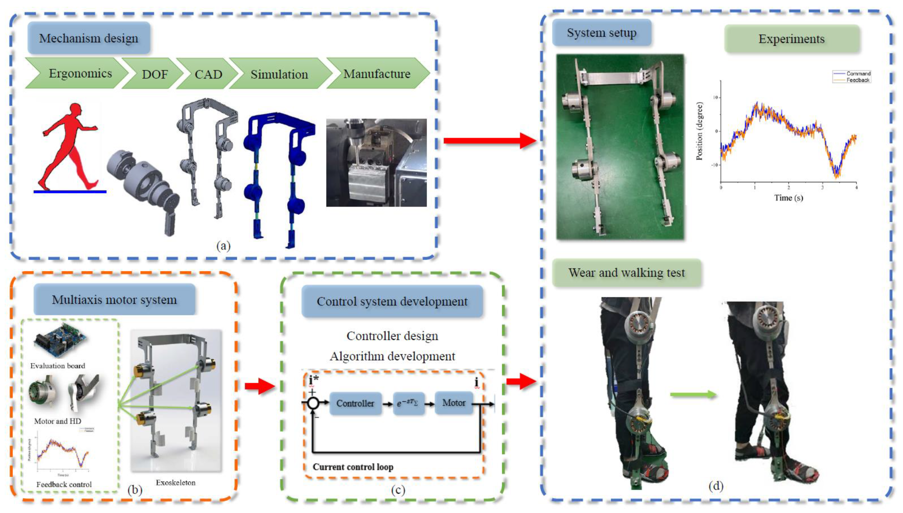
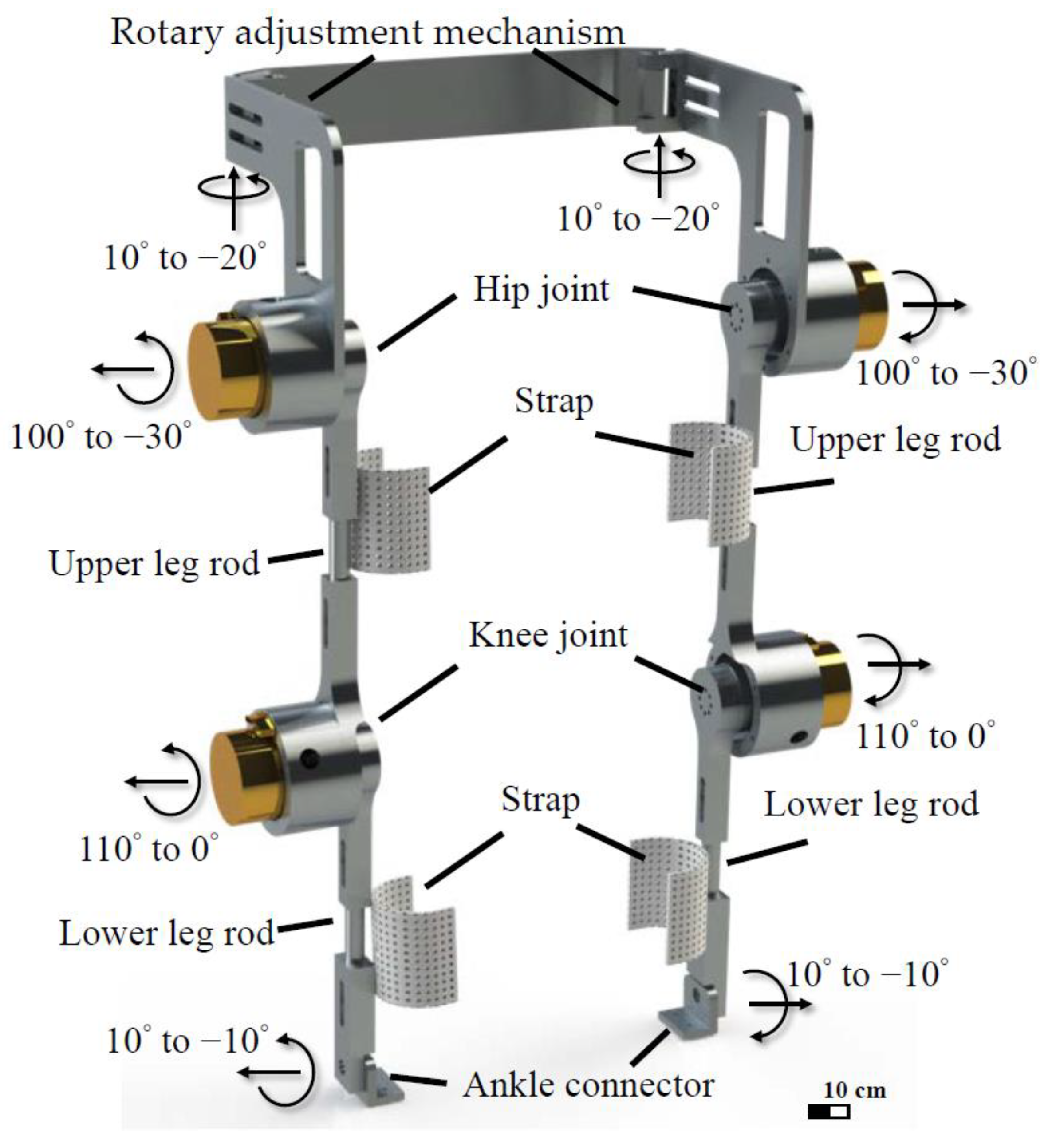
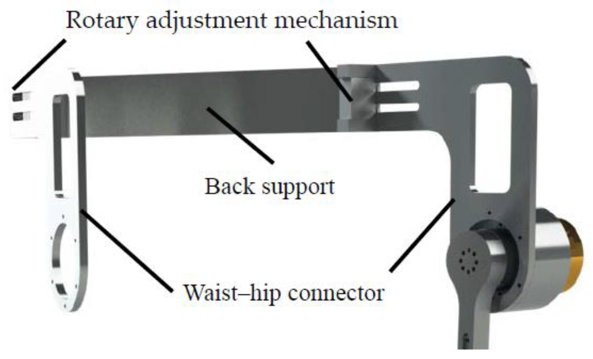
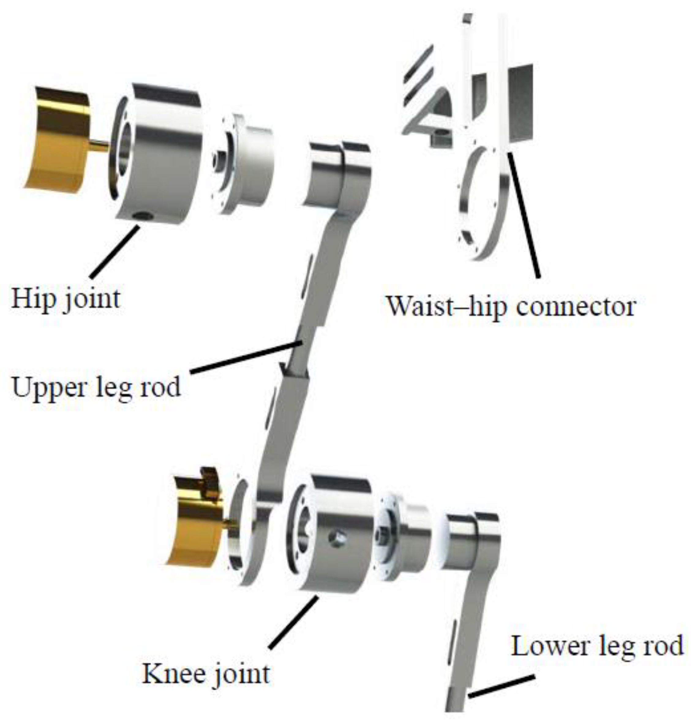
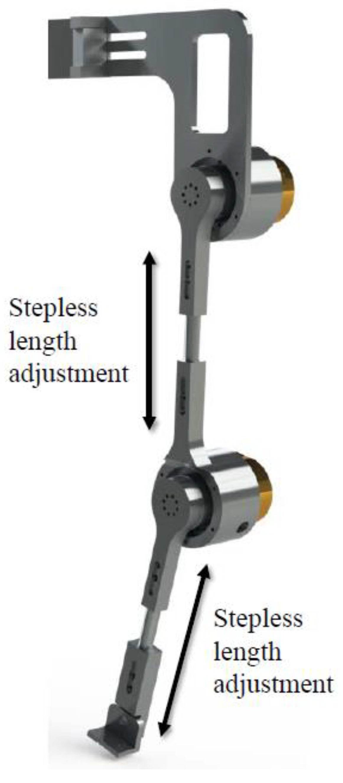
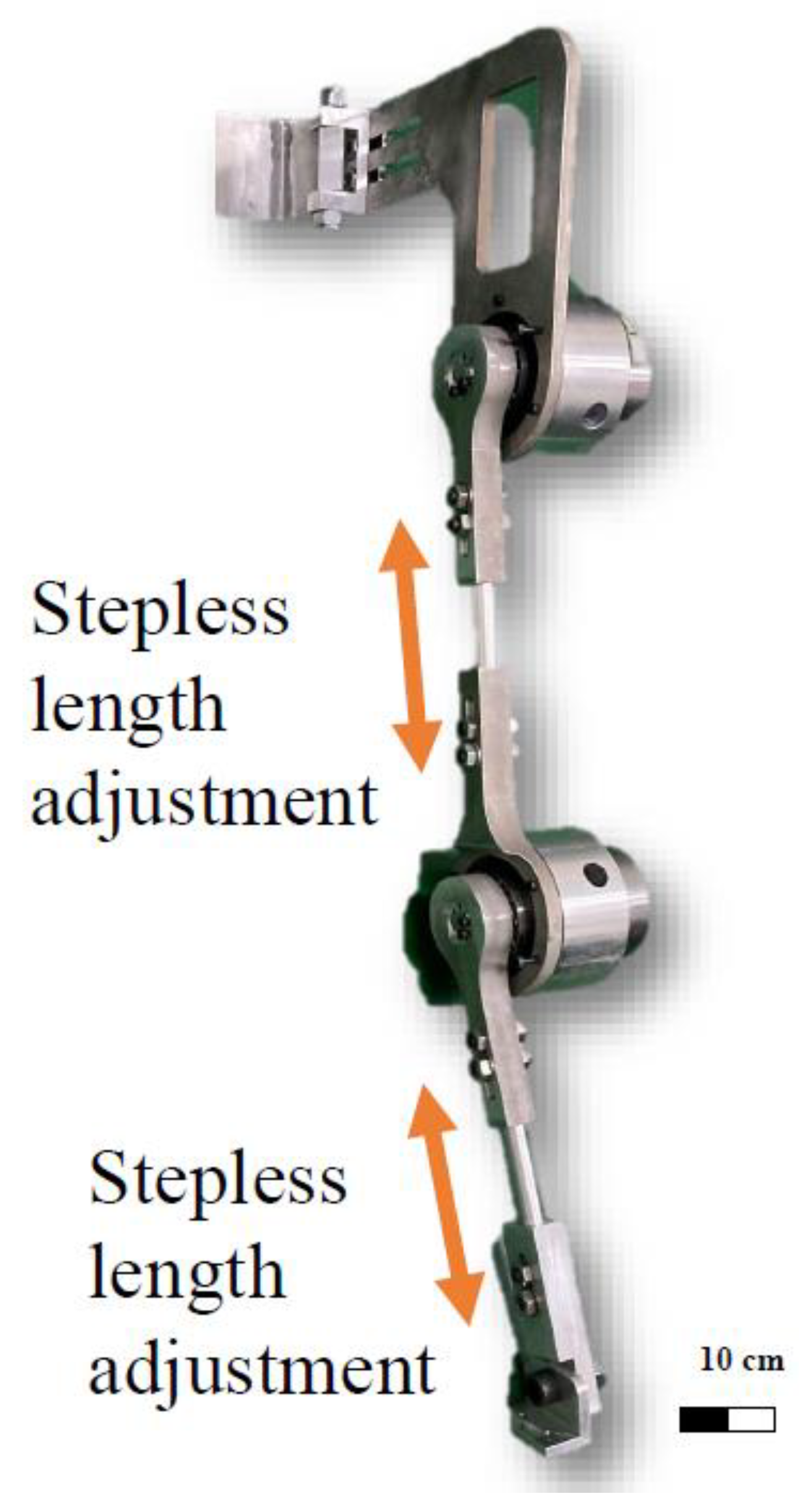
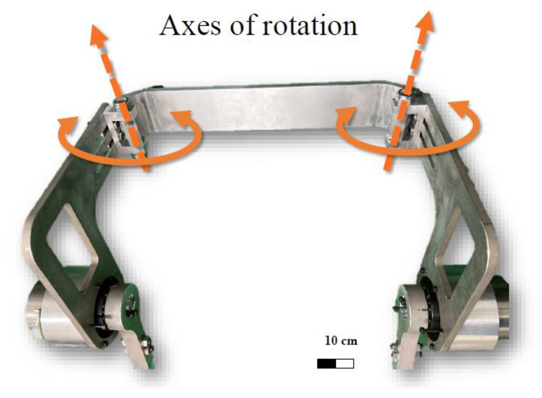
  • A mechanical design involving a stepless (continuous variable lengths) adjustable length was adopted in the novel exoskeleton. To ensure the fit and comfort of the wearer, the axes of rotation were designed on the waist and ankle joints. The entire LLRE-II system weighed 16 kg.
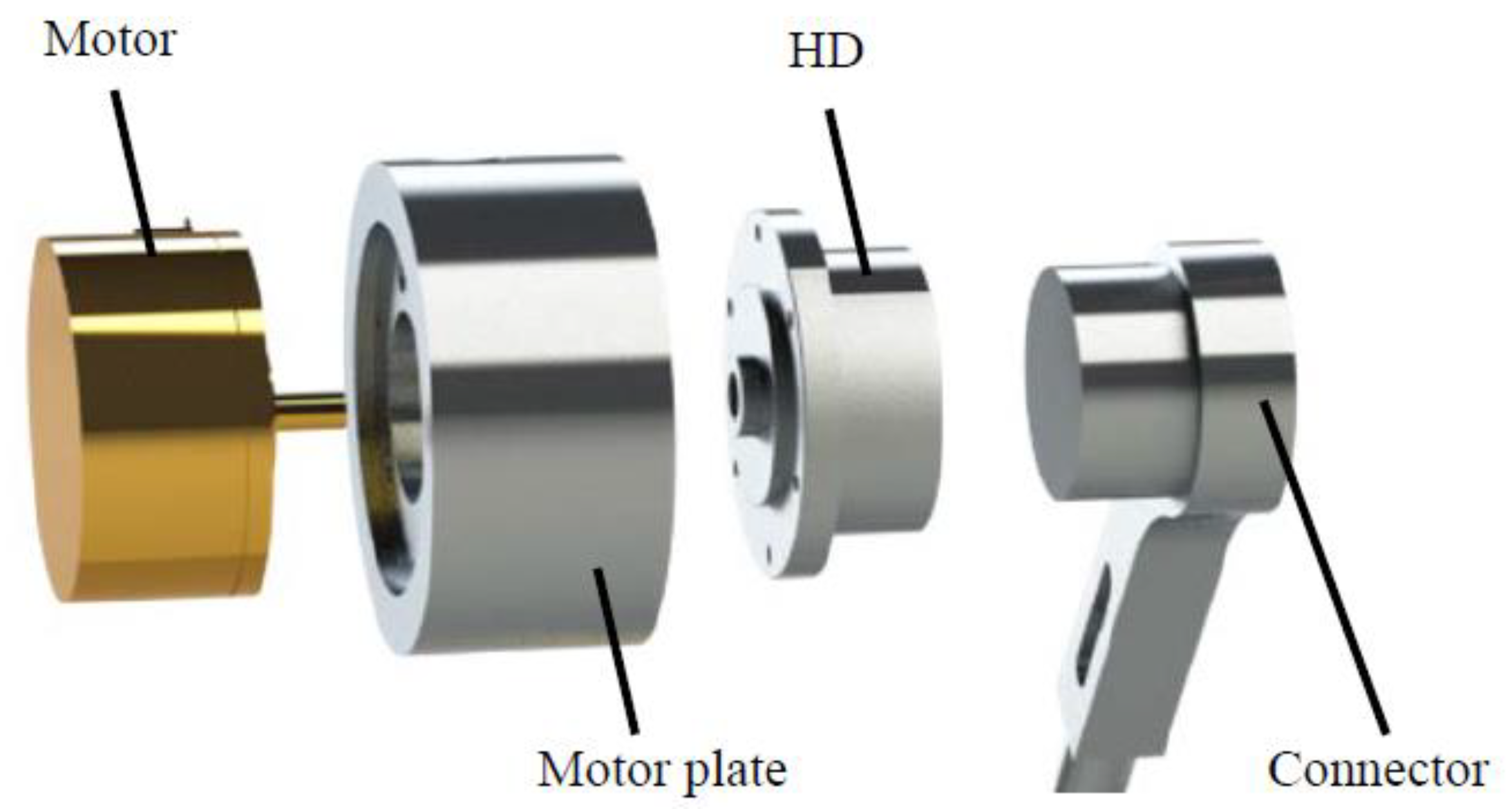
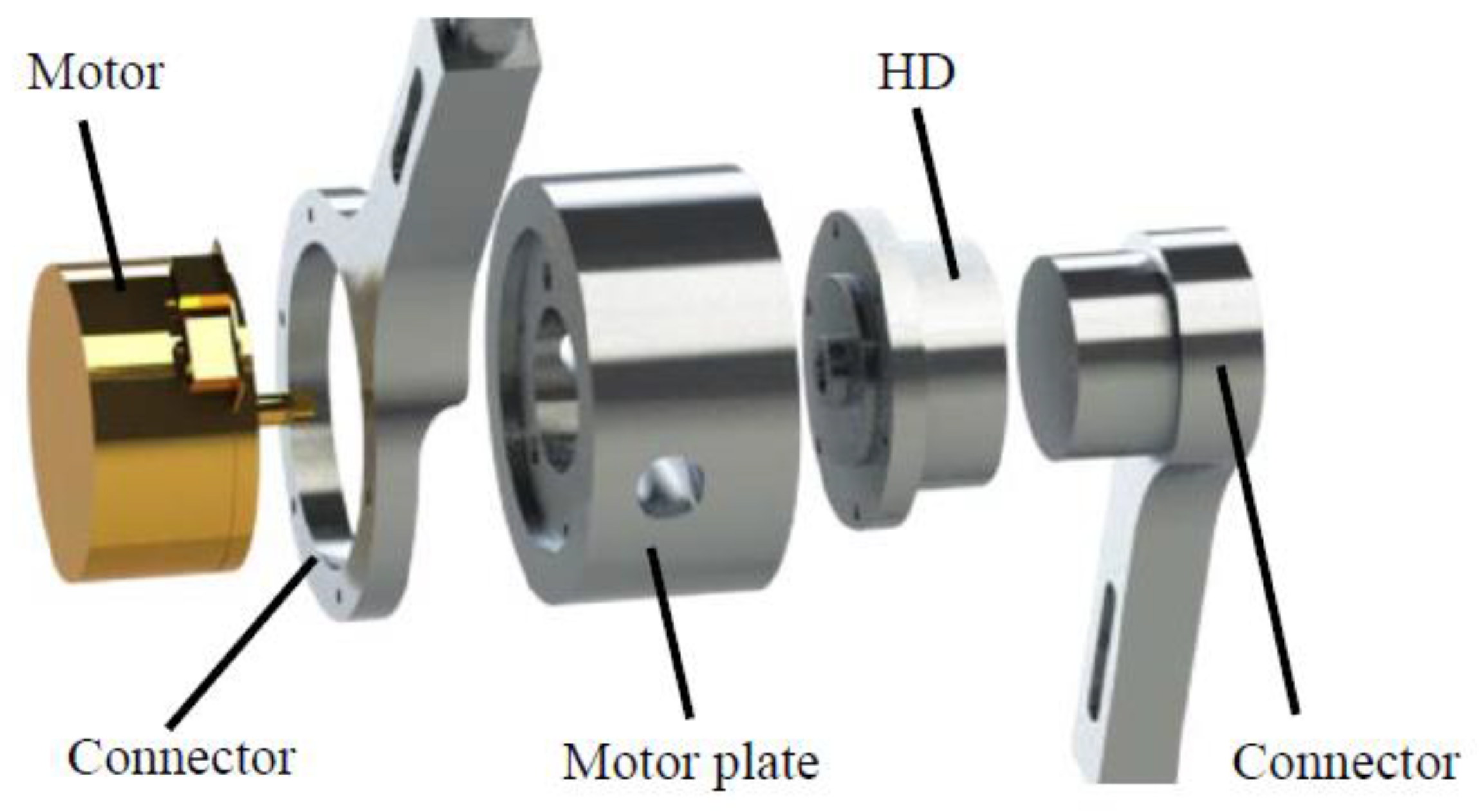
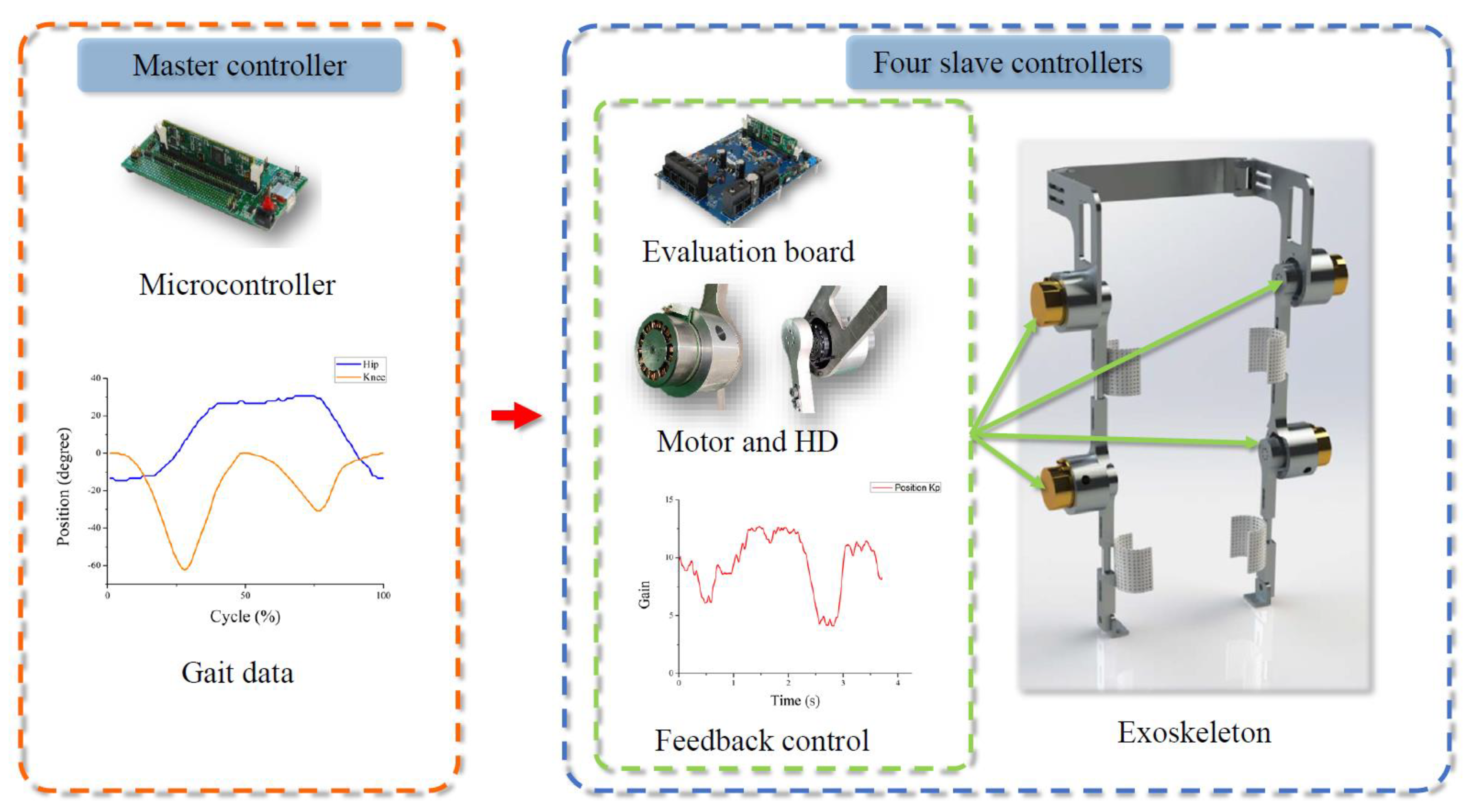
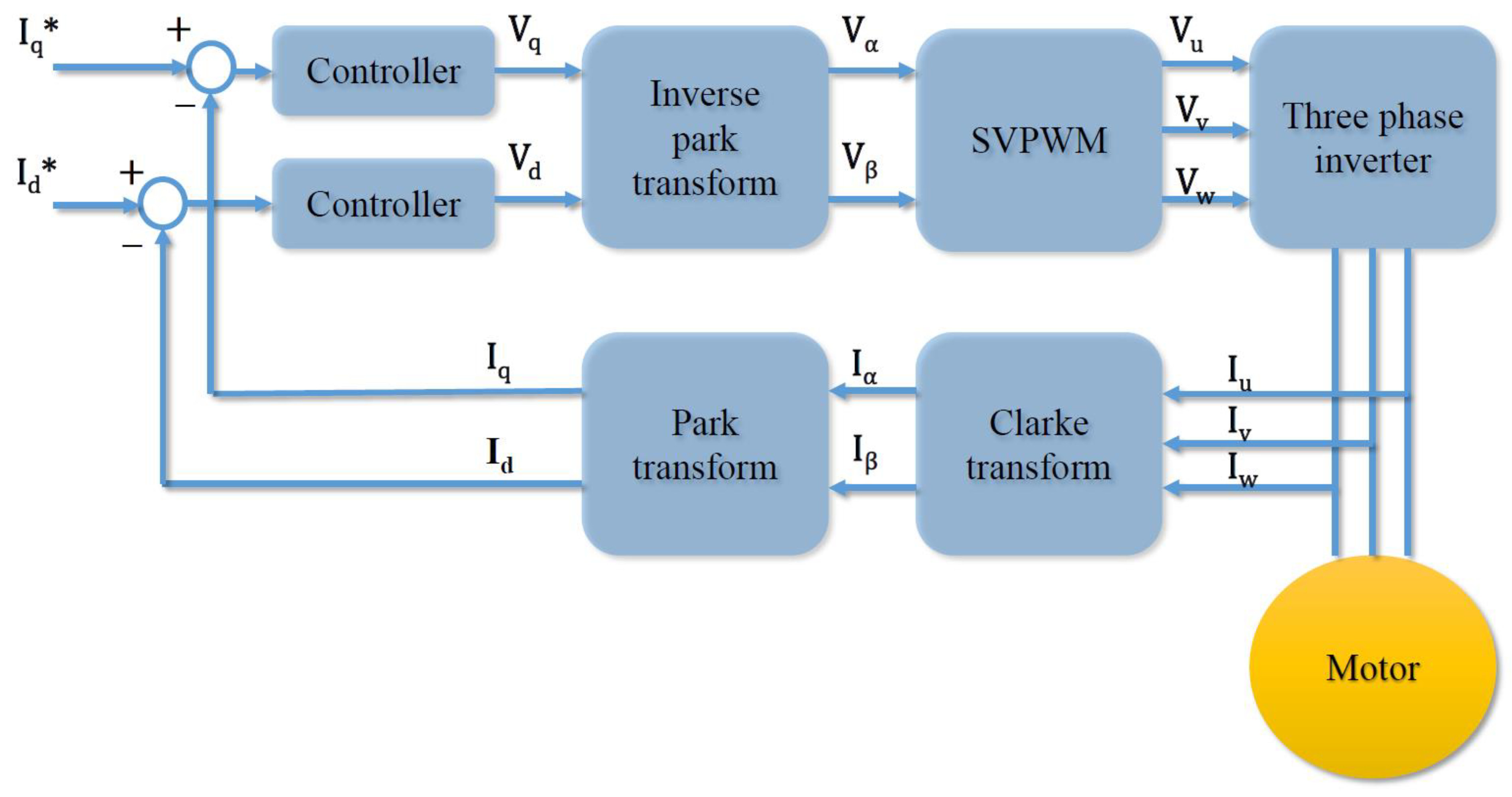
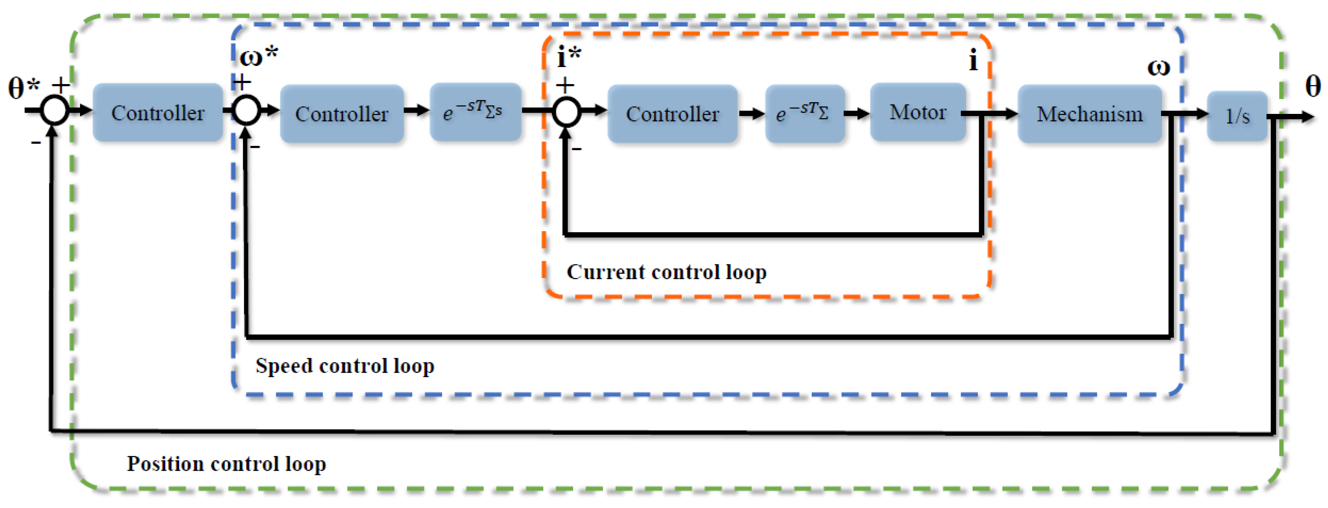
  • A multiaxis (multiple motor control) system was established. Planar motors were installed at the hips and knees of the LLRE-II. Harmonic drives (HDs) were fixed using a connecting plate to the motors to enhance the torque of each joint. The motor drive strategy was based on field-oriented control, including Clarke and Park transformations.
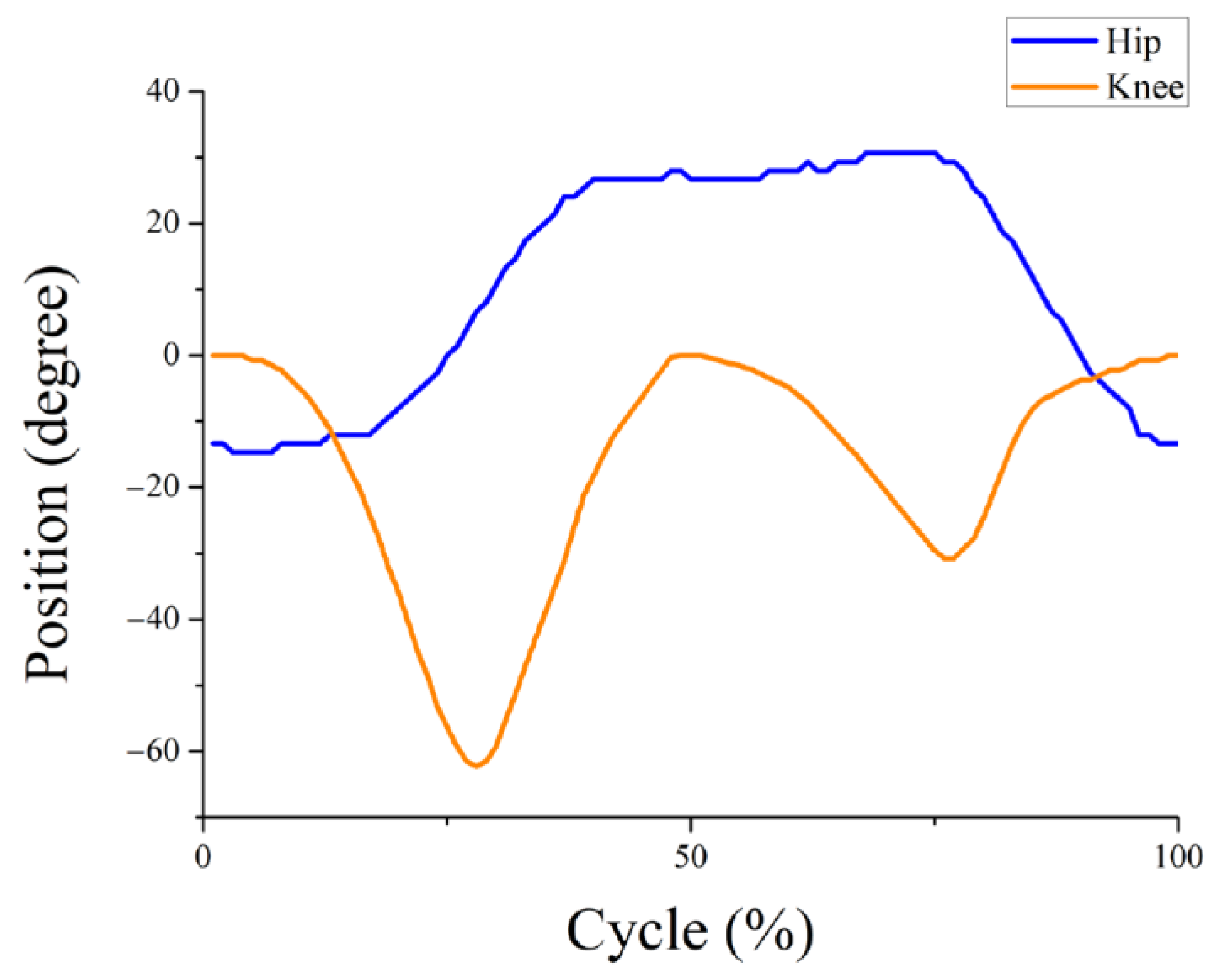
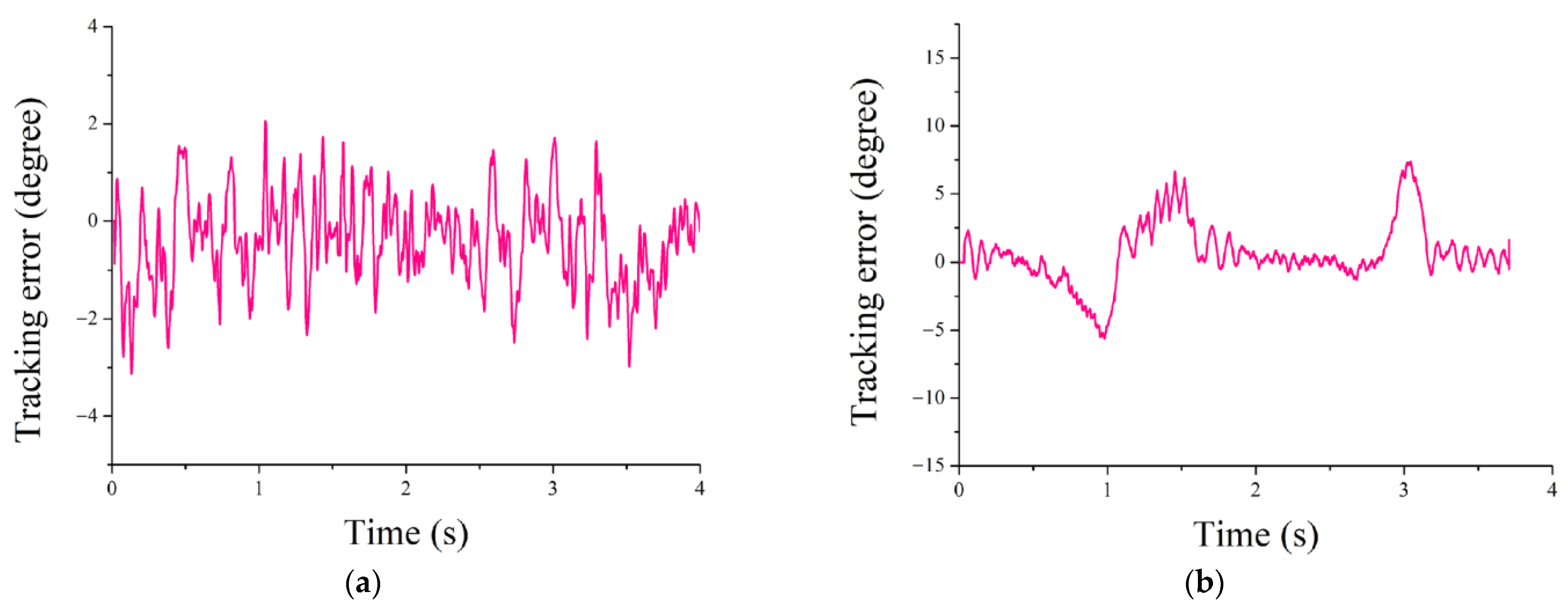
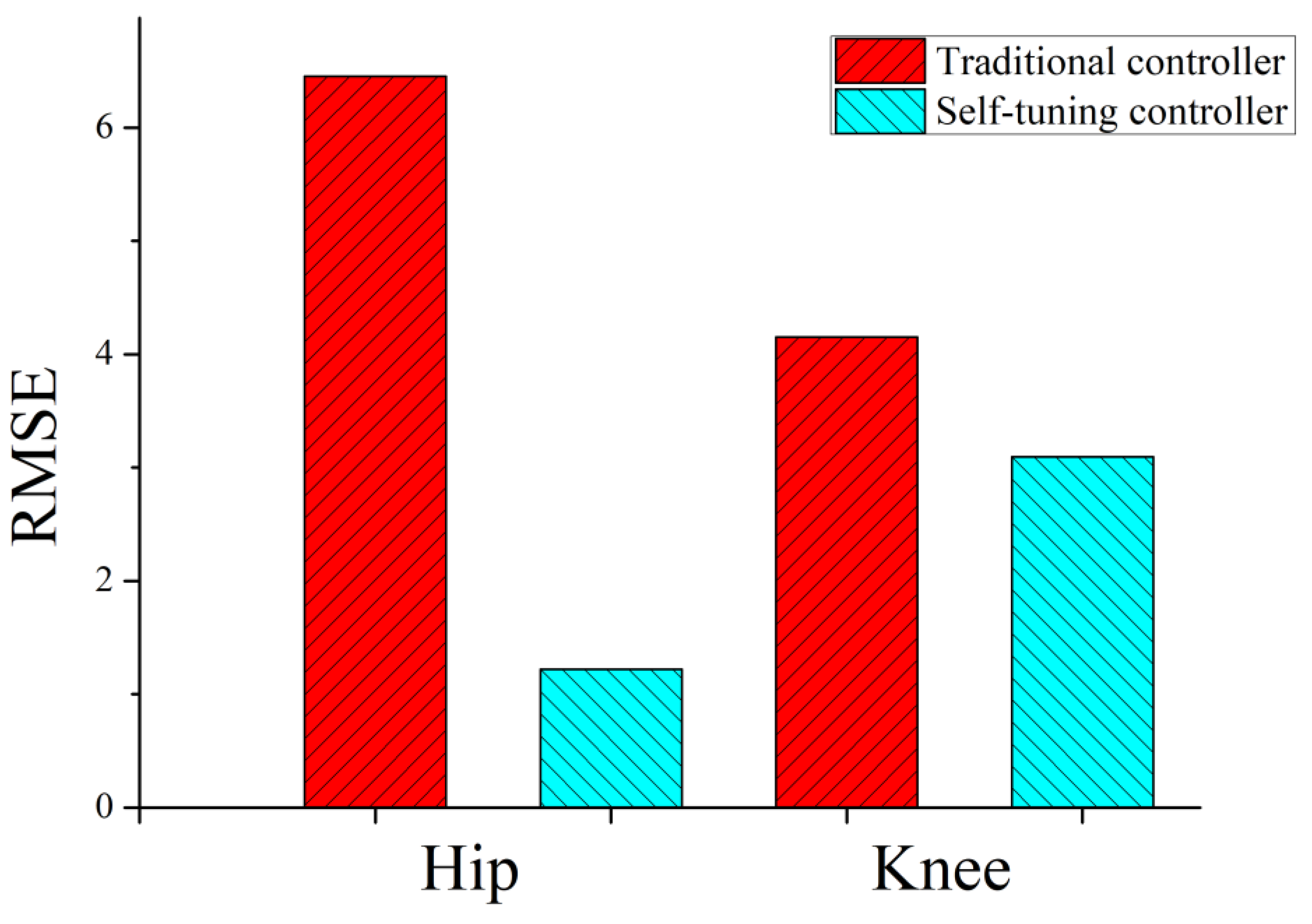
  • The performance of the control system was evaluated. The trajectory tracking of the exoskeleton hip joint and knee during movement was achieved via a designed self-tuning controller. The responses of the exoskeleton system were analyzed.

2. Materials and Methods

2.1. DOF and Range of Motions

The design of the exoskeleton should be determined based on human motion because it is designed for human use. An analytical DOF method is clinical gait analysis, which is used to determine the joint motions of LLEs. In this study, gait patterns were obtained using infrared cameras and a motion capture system (Qualisys Oqus 100, Qualisys Oqus-CMOS, Qualisys AB, Göteborg, Sweden). The captured data were used for mechanical designand control systems. The lower leg of humans can be modeled with seven DOFs, including three DOFs at the waist and hip, one DOF at the knee, and three DOFs at the ankle based on anatomical planes.

2.1.1. Sagittal Plane

The motions of the sagittal plane, also known as the longitudinal plane, allow humans to move ahead. In one gait phase, the knee joint flexes, and the hip joint extends to support the body when the heel is in contact with the ground. This implies that the stance phase begins, and the ankle rocks with the leg rod to move the center of pressure from the heel to the hallux. When the toes are off the ground, the gait phase becomes the swing phase. At this moment, the hip joint flexes until the next heel is in contact with the ground, and the knee joint flexes to maintain the foot in the air.

2.1.2. Coronal Plane

The coronal plane (frontal plane) performs the basic function of balancing the human body. The center of gravity should be within the range of human body projection for a normal walking gait. In the lateral direction, the DOFs of the waist and hip rotate to maintain body balance.

2.1.3. Transverse Plane

Transverse plane motions are along the horizontal axis, which ensures body stability. The foot on the ground rotates around a foot pressure point to maintain the stance phase as another foot swings in the air during the walking cycle. Therefore, the rotation of the hip and ankle joints in the transverse plane ensures that the human walks in a straight line. Furthermore, exoskeletons designed for rehabilitation should restrict the DOFs resulting from unintended motions of wearers with functional limitations. Considering the actual assembly, the impact space of an exoskeleton joint cannot accommodate more than one motor. Therefore, only the required and essential DOFs are prioritized for rehabilitation exoskeletons. Although these restrictions reduce human comfort, the stability and safety of exoskeleton wearers must be ensured.

2.2. Mechanical Design and Simulation

The essential design standards for the LLRE-II are as follows.
(1)
Simple and impactful design for ergonomics
(2)
Flexibility for wearers
(3)
Wearer safety
(4)
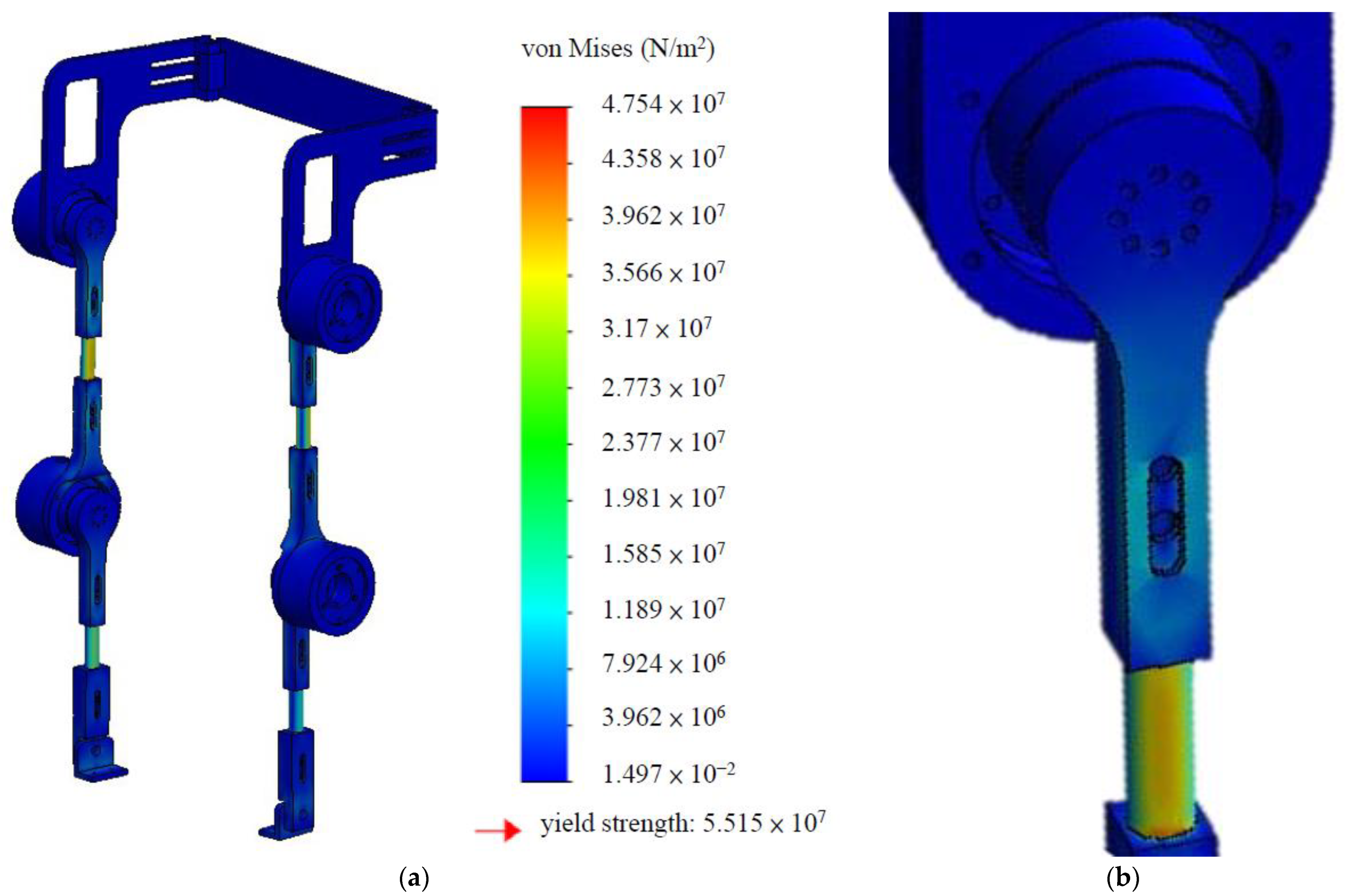
High strength and lightweight
(5)
Economical and easy component renewal
We used SolidWorks software to sketch the preliminary design of the LLRE-II. In terms of ergonomics, the mechanism affords DOFs on the waist, and the mechanical design is symmetrical. The lengths of the leg rods can be adjusted up to 16 mm using stepless length adjustment mechanisms for different wearer heights. To ensure safety, the limits of the joint angles were specified using rotation stoppers to prevent the wearers from being injured. Straps were installed on the leg rods of the exoskeleton to be fixed on the wearer. Furthermore, components such as the leg rods and connectors of the exoskeleton exhibit the same geometry, rendering component renewal easy and economical. The final design of the LLRE-II is shown in Figure 2; it comprises the waist, hip, knee, leg, motor, and foot joints. A stress analysis simulation of the LLRE-II for yield strength and the close-up view of the areas with material tensions, as shown in Figure 3a,b, was performed based on some significant criteria to ensure that the exoskeleton worn by the participants satisfied the theory of failure during walking. The simulation parameters were as follows: (1) material: 6061 aluminum; (2) grid size: 3 mm; (3) nominal torque on the hip and knee joints: 1.21 Nm; (4) weight of wear: 100 kg; and (5) theory of failure: the von Mises yield criterion. The result of the simulation indicated that the critical stress at the leg rod was under the maximum stress and the exoskeleton met the safety criteria. The leg rods were hollowed to be assembled, lightweight, symmetrical for standardization, and easy to manufacture. The hip and knee joints were powered by motors. The components were fabricated using 6061 aluminum to achieve a lightweight but strong structure. The total weight of the LLRE-II, including the motors, was approximately 16 kg.

2.2.1. Waist Design

The waist of the LLRE-II primarily comprises back support, rotary adjustment mechanisms, and waist–hip connectors, as shown in Figure 4. The rotary angles of the back support can be adjusted based on the wearer and walking gait. This adaptive design can maintain the stability of the wearer when yaws occur or disturbances cause lateral external rotations. The back support was 374 mm long and 80 mm wide. The waist–hip connector linked to the hip motor plate was hollow.

2.2.2. Leg Rod, Motor Plate, and Foot Designs

The leg rod and motor plate design are shown in Figure 5. The lower and upper leg rods, motor plate, and other connections of the LLRE-II exhibit the same geometry, affording an economical design and ease of component renewal. As shown in Figure 6, the lengths of the upper and lower leg rods can be adjusted up to 8 mm using stepless length adjustment mechanisms to accommodate different wearer heights. The external and internal diameters of the hollowed-leg rod were 20 and 12 mm, respectively. The hollow-rod design can increase torsional strength and reduce material weight. No actuator was installed at the ankle of the LLRE-II. In fact, the ankle of the LLRE-II comprised a screw, nylon nut, and foot pad, which allowed it to be connected conveniently to the lower leg rod and swing freely.

2.2.3. Hip Joint and Knee Joint Designs

The hip and knee joints were the motive sources with flat motors (EC 90 flat 400W, Maxon, Switzerland) and were designed to satisfy the required DOFs. The hip and knee joint designs are shown in Figure 7 and Figure 8, respectively. The hip and knee joints are not only connected mechanisms but also coupled with motors and HDs. The motor plate comprises a symmetrical hollow cylinder; one side of the motor plate is embedded with the motor, while the other side is installed with an HD to smoothly uprate and transfer torques. We selected an HD with speed reduction ratios of 1:50 and 1:30 for the hip and knee joints, respectively. To ensure safety, we set the limits of the joint angles using rotation stoppers to prevent the wearers from being injured.
The LLRE-II, which is based on a 16-cm stepless length-adjustment mechanism, is designed for humans with heights between 1.64 and 1.80 m. The joint angle ranges of the LLRE-II should be sufficiently large to allow the wearers to completely move their lower limbs. In addition, the LLRE-II joints should limit the wearer from performing unexpected movements to prevent them from moving beyond the range of their joints. Otherwise, the wearer may be injured. The angle range for walking, angle range of humans, and joint angle range of the LLRE-II wearer are listed in Table 1; to achieve comfortable walking, the hip and knee angles of the LLRE-II should be greater than the values shown in the first column (human joint angles when walking) and smaller than those shown in the second column (the angle range of humans) [4,5]. The legs of the LLRE-II are similar to those of human lower limbs in terms of their kinematics and motions.

2.3. Multiaxis Control System

2.3.1. Motor-Driven System Design

The master and slave motor-driven system of the LLRE-II is shown in Figure 9. An embedded microcontroller from TI (TMS320F28069) was used as the master controller, and four TI evaluation boards (TMS320F28069/DRV8301) were used as the slave motor controllers. The master controller provided gait commands to accomplish gait patterns. For improved efficiency, the master controller processed the gait commands only, i.e., it did not perform any other complex calculations, such as tracking errors. By contrast, complex algorithms for feedback control and tracking errors were calculated by the four slave motor controllers. The controller area network bus protocol was used to deliver commands to the slave motor controllers. The obtained gait patterns of comfortable and normal walking gait were used for the gait commands. Thus, the hip and knee joint angles during gait were obtained. These joint angles were used as position commands to control the hip and knee. Additionally, although the healthy gait phases were captured and stored in the master controller, other specific or abnormal gaits were able to be captured and installed in the master controller for unique rehabilitations. The control performance of the position loop is important in LLRE-II controllers. In this study, position control was used to control the motion and trajectory of the LLRE-II. The developed control strategy was applied to the slave controllers for further control applications. The motors on the hips and knees of the LLRE-II were controlled to perform a normal walking gait. The experimental results verified the proposed system design. A block diagram of the developed motor-driven system of the LLRE-II, including the controllers, Park and Clarke transformations, space vector pulse width modulation (SVPWM), three-phase inverter, and motor, is shown in Figure 10. Here, I q * and I d * are the q- and d-axis current commands, respectively; Iq and Id are the q- and d-axis currents, respectively; Vq and Vd are the q- and d-axis voltages, respectively; Iα and I β are the α- and β-axis currents, respectively; Vα and Vβ are the α- and β-axis voltages, respectively; Iu, Iv, and Iw and Vu, Vu, and Vw are the three-phase currents and voltages of the motor, respectively.

2.3.2. Control System Design

A robust and adaptive control system for the exoskeleton allows the latter to be adapted to various walking conditions. The proposed control method includes bandwidth selection and controller gain self-tuning. The parameter tuning method used in this study allows the gain of the controller to be adjusted directly using the current signals of the motor. This results in a simple method that allows the system to provide a fast response and converge to a stable state.
First, the most critical aspect is bandwidth selection. In a motor control system, both Clarke and Park transformations are used to transform operations that convert a three-phase current configuration to the de-referenced direct (D) and quadrature (Q) reference frames as currents id and iq, respectively. The currents of the motor are captured and returned for bandwidth selection. The slope of the current variations (mc) reflects the stability of the motor drive system, as shown in Equation (1).
m c = i q [ N + 1 ] i q [ N ]
The system bandwidth increases with the proportional gain of the controllers and can improve the relative stability and steady-state error. Although an increase in the proportional gain reduces the steady-state error, it affects the relative stability. Therefore, we considered the stability of the controller gain in the motor drive system (sc), as shown in Equation (2).
s c = 0   f o r   m c = 0 s c = 1   f o r   m c < 0 s c = 1   f o r   m c > 0  
After mc and sc are calculated, the mean values of (mc) and (Δmc), i.e., Mmc and Msc, respectively, are calculated using Equations (3) and (4), respectively. Instead of conventional fixed-window methods, the sliding window method was used in this study as it can perform a faster calculation for Msc.
M m c = n N m c 2 [ n ] / N
M s c = n N s c 2 [ n ] / N
As shown in Figure 11a, if Mmc is greater than the maximum mean value of mc, then the controller gain should increase. This step determines whether the system bandwidth increases. As shown in Figure 11b, we classified Msc into unstable, stable, and critical areas using the lower and upper boundaries. When Msc is between the lower and upper boundaries, it is stable. If Msc decreases from the stable area, then the system is unstable. Hence, the controller gain should decrease to allow the system to return to the stable area. However, if Msc is greater than the upper boundary, then the system is in the critical area, and the gain will increase.
Using these criteria, the controller gains can be easily obtained and the system optimized using the feedback values of currents. A flowchart of the proposed strategy is presented in Figure 12.
Second, controller gain self-tuning was developed. We propose a self-tuning method to adjust the control gains of the motor control system, including the current, speed, and position loops. The architecture of the control system of the LLRE-II is shown schematically in Figure 13, where θ*, ω*, and i* are the position, voltage, and current commands, respectively, and θ, ω, and i are the position, voltage, and current feedback values, respectively.
For the current loop, the open-loop transfer function (Go,current) is expressed as shown in Equation (5). It primarily comprises a PI controller and a motor electrical model.
G o , c u r r e n t = k p c ( 1 + 1 s T i c ) 1 R m + s L m e s T
where kpc and Tic are the PI controller gain and time constant, respectively; TΣ is the delay time; I* and I are the command and feedback of the current, respectively; and Lm and Rm are the inductance and resistance of the motor, respectively. The open-loop transfer function can be rewritten based on pole–zero elimination, as shown in Equation (6).
G o , c u r r e n t = k p c L m s e s T Σ = w c T Σ s e s T Σ
where wc is the searched bandwidth gain.
Subsequently, kpc is expressed as
k p c = w c L m T Σ
The phase margin of the current loop (PMc) is derived using Equation (8).
P M c = 90 °   -   ( 180 ° π w c )
Hence, the relationship between the phase margin and controller parameters is obtained. Once the optimal bandwidth of the current controller is selected using the proposed method, the controller gains are adjusted automatically. Based on Equation (8), the current loop is regarded as stable when PMc is between 30° and 60°. Typically, phase margins between 30° and 60° result in reasonable tradeoffs between the bandwidth and stability.
Next, the speed control loop is modeled, and the open-loop transfer function is represented by Equation (9). The speed loop comprises a PI controller and a motor mechanical model. All the dead and delay times of the speed control loop (TΣs) are merged into a single delay time. The controller gain (kps) is expressed as shown in Equation (10).
G o , s p e e d = K p s ( 1 + 1 s T i s ) ( 1 J s + B ) G o , c u r r e n t 1 1 + s T s
k p s = J T Σ s · w s ,
where J and B are the inertia and friction coefficient of the system, respectively.
The phase margin of the speed loop (PMs) is derived using Equation (11).
P M s = 2 tan 1 w s π 2 ,
where ws is defined as 1/(wckr), and kr is the ratio of kps to kpc.
The position closed-loop transfer function is derived, and the position control gain is determined using Equations (12) and (13).
G c , p o s i t i o n = k p p s + k p p
k p p = 1 / T i s
Hence, the system is evaluated using the bandwidth selection and controller gain self-tuning methods. After the system bandwidth is obtained, the system stability is verified based on the phase margins of the current and speed loops. The controller gains are calculated synchronously when the phase margins are not between 30° and 60°. In summary, the proposed self-tuning method yields faster responses and better tracking errors compared with other methods.

3. Results and Discussion

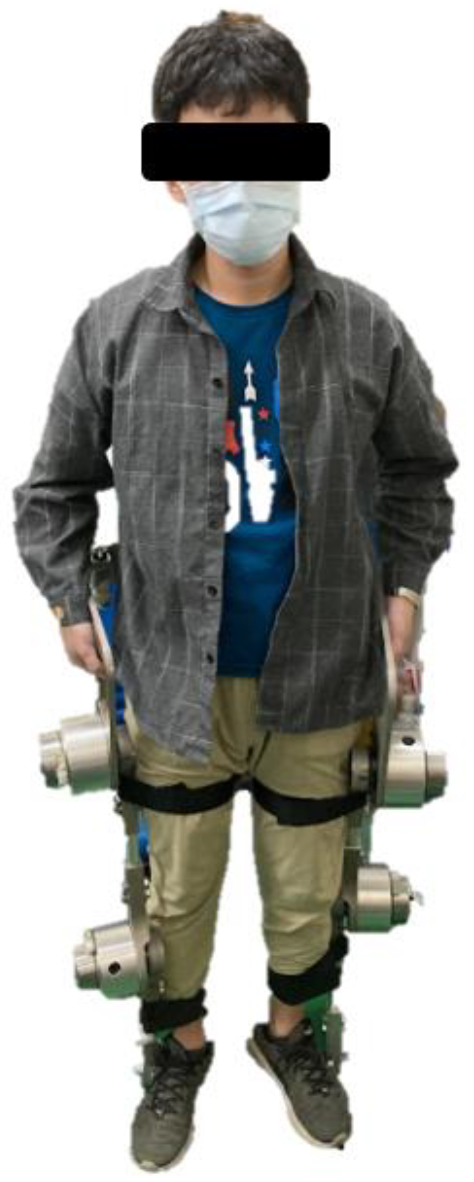
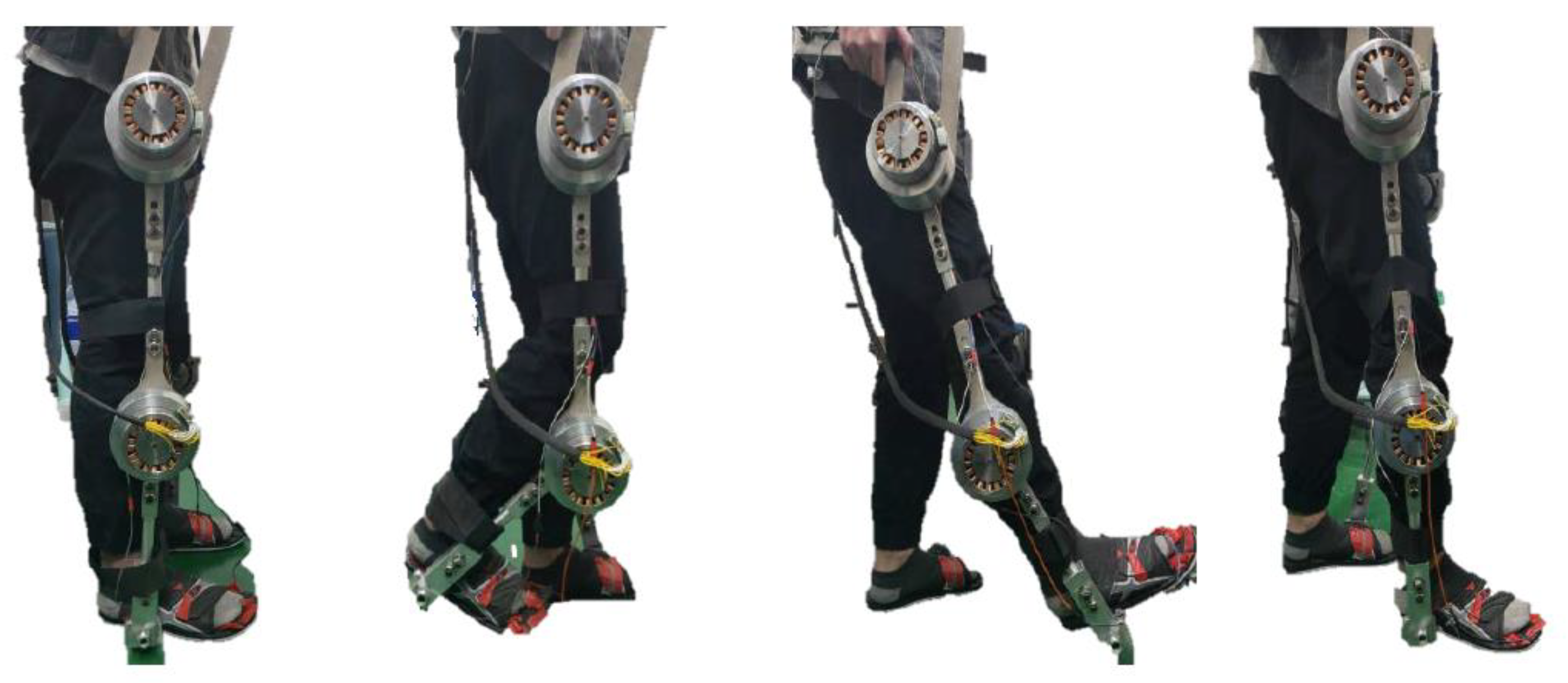
3.1. Test of the Exoskeleton Worn by the Participant

The DOFs of the LLE were designed to model those of the lower extremity of humans. Based on the design concept, the hip and knee joints of the LLRE-II are driven by motors with safety limits in the sagittal plane for the requirement of walking. In the coronal plane, motion is required to maintain balance. The walking direction and comfort of the wearer are considered for the waist, hip, and knee joints. Meanwhile, the rotations of the ankle joints are restricted.
The exoskeleton was manufactured via computerized numerical control machining to achieve improved machining accuracy. Aluminum 6061 was used as the material for the components owing to its high fatigue strength and machinability. The structure of the exoskeleton was designed to achieve easy disassembly, fast component replacement, and cost reduction. The LLRE-II was developed to support the walking motion of individuals, as shown in Figure 14. The limb rods were hollow and adjustable for various heights of the wearer, as shown in Figure 15. A front view of the waist of the LLRE-II is shown in Figure 16, where the two axes of rotation allow the wearer to be fitted well and comfortably. The exoskeleton was evaluated while being worn by a walking participant, as shown in Figure 17. The height and weight of the wearer were 173 cm and 65 kg, respectively. Straps were installed on the thighs and calves of the exoskeleton to be fixed on the wearer. The wearer was able to adjust the length of the LLRE-II before walking. For the preliminary test, walking data without the exoskeleton were obtained using infrared cameras and a motion-capture system. Those data can be used to establish the basic concept for determining the rotation angles of the LLRE-II joints, motor output power, and corresponding control strategy. The gait data for normal walking motion are shown in Figure 18.

3.2. Conventional PI Controller

Figure 19a,b show the tracking performances of a conventional PI controller for the gait of the hip and knee motors. The phase margins of the current and speed loops were set at 45°, and the gaits were evaluated. The results showed that the response of the hip was relatively good, and the average tracking error was approximately 1.37°, as shown in Figure 20a. However, the response of the knee was unsatisfactory as compared with that of the hip, and the average tracking error was 3.14°, as shown in Figure 20b.

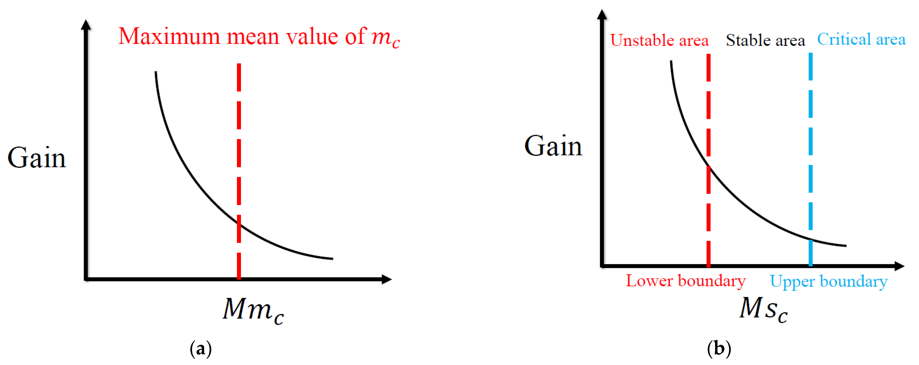
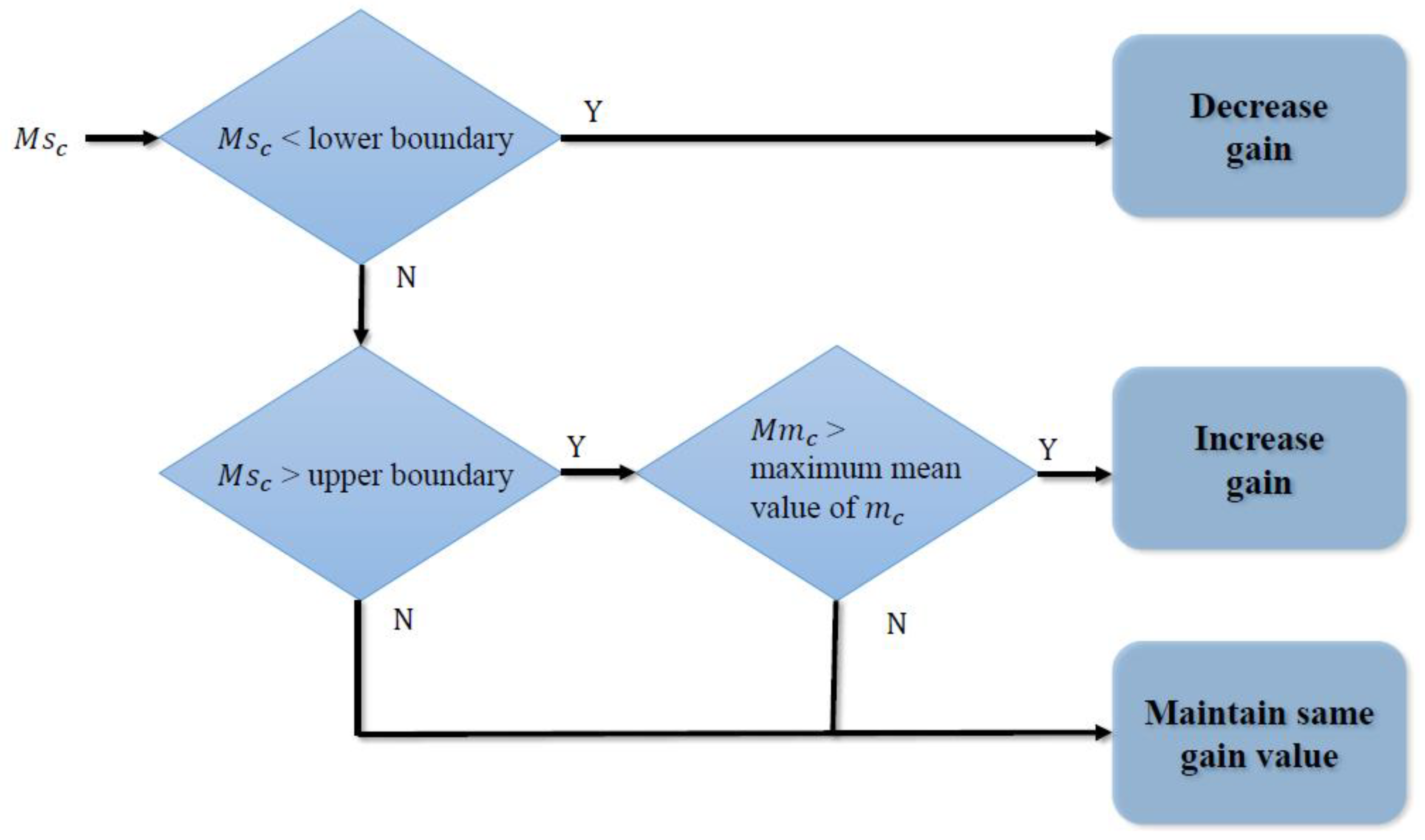
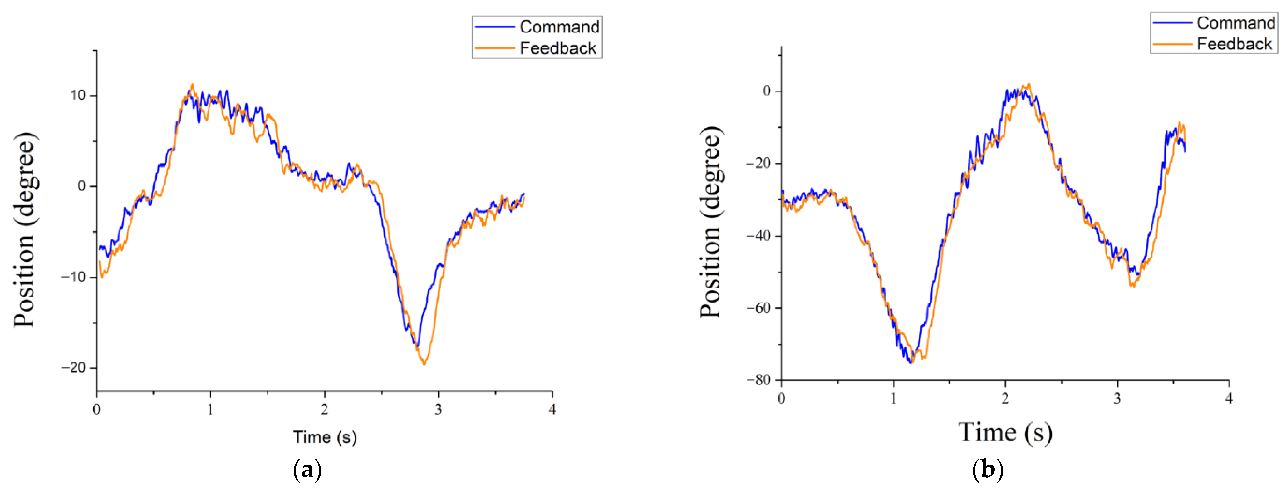
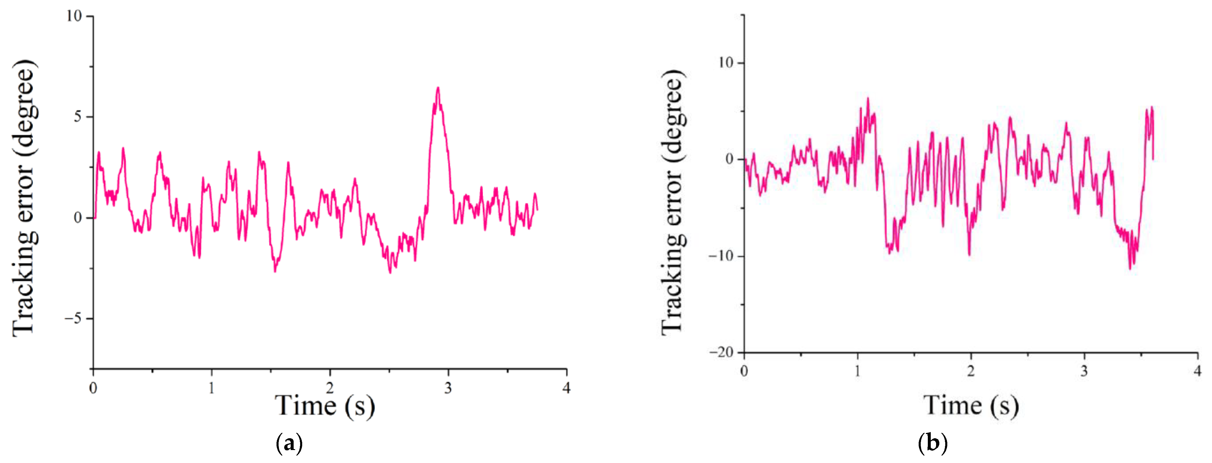
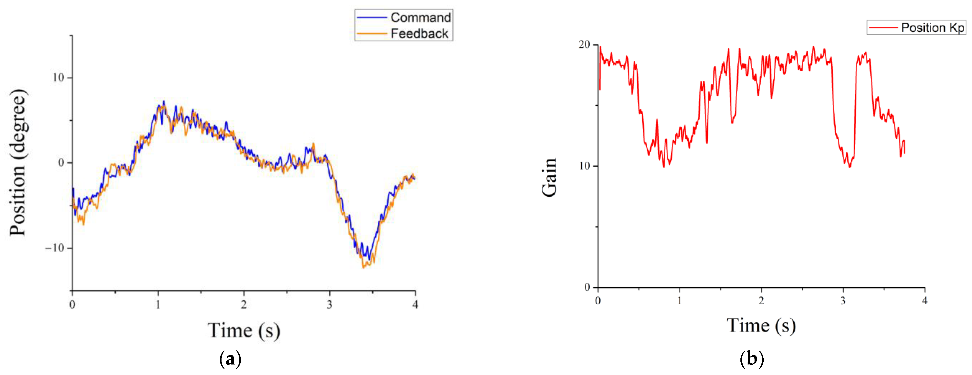
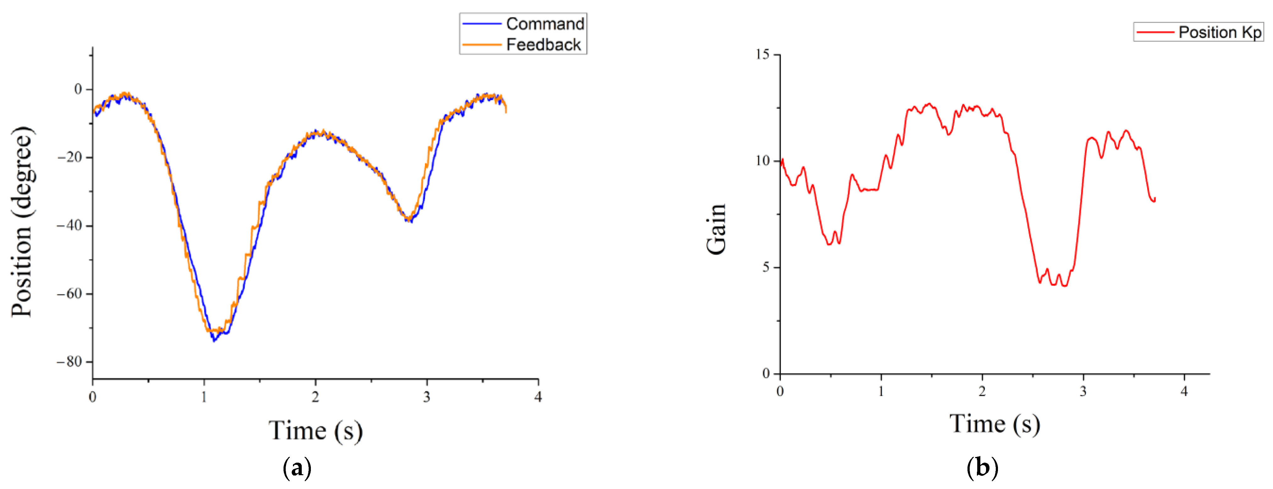
3.3. Self-Tuning Controller

The proposed self-tuning method can synchronously adjust the controller gains based on the system conditions. In addition, the stability of the system can be ensured via the phase-margin design of the system. Figure 21a,b and Figure 22a,b show the results of hip and knee responses obtained by modulating the gains of the control loops using the proposed self-tuning control strategy, respectively, where the controller gains are obtained from 7 to 20 for the hip responses and from 3 to 14 for the knee responses. The responses and stability of the system improved, and the average tracking errors were 0.96° and 2.35° for the hip and knee, respectively, as shown in Figure 23a,b, respectively. This is because the variations in the controller gains were adjusted based on the slopes of the system currents. Because the boundaries of the controller gains can be appropriately controlled by the phase margins, system instability was avoided.

3.4. Discussion and Related Studies

To compare the performances of the abovementioned methods, the root mean square error (RMSE) was defined to analyze the experimental results as follows:
R M S E = n = 1 N r e ( n ) 2 / N r ,
where e(n) is the tracking error, and Nr is the tracking error size.
Figure 24 shows the RMSE results for the conventional and self-tuning controllers, where the self-tuning controller indicates lower RMSEs, i.e., 1.22 and 3.09 for the hip and knee, respectively. In general, the RMSE reduced from 6.45 to 1.22 for the hip joint and from 4.15 to 3.09 for the knee joint.
Challenges pertaining to the development of the exoskeleton system have been reported in previous studies. One of the challenges is the development of the exoskeleton mechanism and control algorithm for addressing human–machine movements and facilitating rehabilitation. Another challenge is the optimization of the exoskeleton system to enable its adaptation to different individuals and tasks. In this study, a novel mechanism for an LLE with a lightweight but strong structure was developed. The hip and knee joints are powered by motors and HDs, respectively. Furthermore, a self-tuning controller was developed to optimize the control structure. The experimental results showed improved system performance. Table 2 presents the differences between a few relevant previous studies and our study. In future, the exoskeleton will remain indispensable in the rehabilitation field for aiding people with disabilities. Exoskeleton systems with high efficiency and flexibility are expected to be manufactured at a large scale prior to their deployment to users in daily life.

4. Conclusions

A lower-limb rehabilitation exoskeleton named LLRE-II was developed to assist people with walking disabilities. The mechanical design of the LLRE-II allowed the length to be adjusted to fit wearers of different heights. A lightweight but strong structure was designed using a hollow rod fabricated using aluminum 6061 material with high strength and ductility. The total weight of the LLRE-II, including the motors, was 16 kg. The design of the LLRE-II was based on the DOFs of human lower legs. Therefore, four DOFs for one leg were considered for the rehabilitation exoskeletons. In addition to joint movements at the hip and knee joints, the two axes of rotation at the waist allowed the wearer to be fitted well and comfortably. Computer-aided designs and simulations were performed to satisfy these requirements. The LLRE-II was manufactured using computerized numerical control machining to ensure adequate machining accuracy. Furthermore, the LLRE-II was integrated with a multiaxis motor control system. The joints of the hip and knee were operated by motors and HDs, respectively. A TI microcontroller was used as the master controller, and four TI evaluation boards were used as the slave motor controllers. The conventional controller design and self-tuning controller were compared in the gait experiment of the LLRE-II. The self-tuning controller yielded better responses and eliminated oscillations. The RMSE of the hip decreased significantly by 81% (from 6.45 to 1.22). The performance of the LLRE-II was evaluated, and the experimental results showed that the designed controllers and mechanical design exhibited satisfactory performance in terms of motion control. The LLRE-II developed based on a master–slave controller strategy demonstrated potential for further applications, such as for training muscles and assisting injury recovery.

Author Contributions

Conceptualization, M.-C.L., C.-T.P. and K.-M.L.; methodology, C.-T.P.; software, J.-S.H. and M.-C.L.; validation, J.-S.H. and M.-C.L.; formal analysis, M.-C.L.; investigation, C.-C.C., J.-S.H. and M.-C.L.; resources, Z.-Y.H.; data curation, Z.-Y.H. and M.-C.L.; writing—original draft preparation, M.-C.L.; writing—review and editing, C.-T.P. and K.-M.L.; visualization, M.-C.L.; supervision, K.-M.L.; project administration, C.-T.P. and K.-M.L.; funding acquisition, C.-T.P. All authors have read and agreed to the published version of the manuscript.

Funding

This research was funded by grant VGHNSU111-015 from Kaohsiung Veterans General Hospital, Taiwan.

Institutional Review Board Statement

Not applicable.

Informed Consent Statement

Informed consent was obtained from all subjects involved in the study.

Data Availability Statement

Not applicable.

Conflicts of Interest

The authors declare no conflict of interest.

References

  1. Cenciarini, M.; Dollar, A.M. Biomechanical Considerations in the Design of Lower Limb Exoskeletons. In Proceedings of the 2011 IEEE International Conference on Rehabilitation Robotics, Zurich, Switzerland, 29 June 2011; p. 5975366. [Google Scholar] [CrossRef]
  2. Jatsun, S.; Savin, S.; Yatsun, A.; Postolnyi, A. Control system parameter optimization for lower limb exoskeleton with integrated elastic elements. In Advances in Cooperative Robotics; World Scientific Publishing: Singapore, 2017; pp. 797–805. [Google Scholar]
  3. Liu, D.X.; Wu, X.; Du, W.; Wang, C.; Chen, C.; Xu, T. Deep spatial-temporal model for rehabilitation gait: Optimal trajectory generation for knee joint of lower-limb exoskeleton. Assem. Autom. 2017, 37, 369–378. [Google Scholar] [CrossRef]
  4. Kirtley, C. CGA Normative Gait Database; Hong Kong Polytechnic University: Hong Kong, China, 2005. [Google Scholar]
  5. Zheng, X.; Jia, S.; Gao, Y.; Hou, M.; Xi, D.; Yang, H. Modern Sports Biomechanics; National Defense Industry Press: Beijing, China, 2002; pp. 100–163. [Google Scholar]
  6. Makinson, B.J. Research and Development Prototype for Machine Augmentation of Human Strength Endurance, Hardiman I Project; Tech. Rep. S-71-1056; General Electric Company: Schenectady, NY, USA, 1971. [Google Scholar]
  7. Yamamoto, K.; Hyodo, K.; Ishii, M.; Matsuo, T. Development of power assisting suit for assisting nurse labor. JSME Int. J. Ser. C Mech. Syst. Mach. Elem. Manuf. 2002, 45, 703–711. [Google Scholar] [CrossRef] [Green Version]
  8. Kazerooni, H.; Steger, R.; Huang, L. Hybrid control of the Berkeley lower extremity exoskeleton (BLEEX). Int. J. Robot. Res. 2006, 25, 561–573. [Google Scholar] [CrossRef]
  9. Zoss, A.B.; Kazerooni, H.; Chu, A. Biomechanical design of the Berkeley lower extremity exoskeleton (BLEEX). IEEE ASME Trans. Mechatron. 2006, 11, 128–138. [Google Scholar] [CrossRef]
  10. Chen, C.-F.; Du, Z.; He, L.; Shi, Y.; Wang, J.; Xu, G.; Zhang, Y.; Wu, D.; Dong, W. Development and hybrid control of an electrically actuated lower limb exoskeleton for motion assistance. IEEE Access 2019, 7, 169107–169122. [Google Scholar] [CrossRef]
  11. Han, J.; Yang, S.; Xia, L.; Chen, Y. Deterministic adaptive robust control with a novel optimal gain design approach for a fuzzy 2DOF lower limb exoskeleton robot system. IEEE Trans. Fuzzy Syst. 2020, 29, 2373–2387. [Google Scholar] [CrossRef]
  12. Zhang, X.; Li, J.; Ovur, S.E.; Chen, Z.; Li, X.; Hu, Z.; Hu, Y. Novel design and adaptive fuzzy control of a lower-limb elderly rehabilitation. Electronics 2020, 9, 343. [Google Scholar] [CrossRef] [Green Version]
  13. Bocker, J.; Beineke, S.; Bahr, A. On the Control Bandwidth of Servo Drives. In Proceedings of the 13th European Conference on Power Electronics and Applications, Barcelona, Spain, 8–10 September 2009. [Google Scholar]
  14. Hsu, C.-J.; Lai, Y. Novel online optimal bandwidth search and autotuning techniques for servo motor drives. IEEE Trans. Ind. Appl. 2017, 53, 3635–3642. [Google Scholar] [CrossRef]
  15. Pan, C.-T.; Chang, C.-C.; Yang, Y.-S.; Yen, C.-K.; Liu, C.-C.; Lee, C.-L.; Shiue, Y.-L. Development a multi-loop modulation method on the servo drives for lower limb rehabilitation exoskeleton. Mechatronics 2020, 68, 102360. [Google Scholar] [CrossRef]
  16. Liu, J.; Fang, H.; Xu, J. Online Adaptive PID control for a multi-joint lower extremity exoskeleton system using improved particle swarm optimization. Machines 2022, 10, 21. [Google Scholar] [CrossRef]
  17. Lu, Z.; Ye, D.; Chen, Q.; Liu, C.; Dong, H.; Cheng, D. Adaptive adjustment strategy for walking characteristics of single-legged exoskeleton robots. Machines 2022, 10, 134. [Google Scholar] [CrossRef]
  18. Chen, S.; Han, T.; Dong, F.; Lu, L.; Liu, H.; Tian, X.; Han, J. Precision interaction force control of an underactuated hydraulic stance leg exoskeleton considering the constraint from the wearer. Machines 2021, 9, 96. [Google Scholar] [CrossRef]
  19. Rodríguez-Fernández, A.; Lobo-Prat, J.; Font-Llagunes, J.M. Systematic review on wearable lower-limb exoskeletons for gait training in neuromuscular impairments. J. Neuroeng. Rehabil. 2021, 18, 22. [Google Scholar] [CrossRef] [PubMed]
  20. Li, W.-Z.; Cao, G.-Z.; Zhu, A.-B. Review on control strategies for lower limb rehabilitation exoskeletons. IEEE Access 2021, 9, 123040–123060. [Google Scholar] [CrossRef]
  21. Lovrenovic, Z.; Doumit, M. Review and Analysis of Recent Development of Lower Extremity Exoskeletons for Walking Assist. In Proceedings of the 2016 IEEE EMBS International Student Conference (ISC), Ottawa, ON, Canada, 29–31 May 2016; pp. 1–4. [Google Scholar] [CrossRef]
  22. Del-Ama, A.J.; Koutsou, A.D.; Moreno, J.C.; de-los-Reyes, A.; Gil-Agudo, N.; Pons, J.L. Review of hybrid exoskeletons to restore gait following spinal cord injury. JRRD 2012, 49, 497. [Google Scholar] [CrossRef]
  23. Arya, K.N.; Pandian, S.; Kumar, V. Effect of activity-based mirror therapy on lower limb motor-recovery and gait in stroke: A randomised controlled trial. Neuropsychol. Rehabil. 2019, 29, 1193–1210. [Google Scholar] [CrossRef]
  24. Önen, Ü.; Botsalı, F.M.; Kalyoncu, M.; Tınkır, M.; Yılmaz, N.; Şahin, Y. Design and actuator selection of a lower extremity exoskeleton. IEEE/ASME Trans. Mechatron. 2014, 19, 623–632. [Google Scholar] [CrossRef]
  25. Xia, L.; Feng, Y.; Chen, F.; Wu, X. A Bio-Signal Enhanced Adaptive Impedance Controller for Lower Limb Exoskeleton. In Proceedings of the IEEE International Conference of Robotic Automation (ICRA), Paris, France, 31 May–31 August 2020; pp. 4739–4744. [Google Scholar]
  26. Wang, C.; Wu, X.; Wang, Z.; Ma, Y. Implementation of a braincomputer interface on a lower-limb exoskeleton. IEEE Access 2018, 6, 38524–38534. [Google Scholar] [CrossRef]
  27. Molazadeh, V.; Zhang, Q.; Bao, X.; Sharma, N. An iterative learning controller for a switched cooperative allocation strategy during sit-tostand tasks with a hybrid exoskeleton. IEEE Trans. Control Syst. Technol. 2021, 30, 1021–1036. [Google Scholar] [CrossRef]
  28. Cardona, M.; Cena, C.E.G.; Serrano, F.; Saltaren, R. ALICE: Conceptual development of a lower limb exoskeleton robot driven by an on-board musculoskeletal simulator. Sensors 2020, 20, 789. [Google Scholar] [CrossRef] [Green Version]
  29. Song, B.; Lee, D.; Park, S.Y.; Baek, Y.S. A novel method for designing motion profiles based on a fuzzy logic algorithm using the hip joint angles of a lower-limb exoskeleton robot. Appl. Sci. 2020, 10, 6852. [Google Scholar] [CrossRef]
Figure 1. Study design of the LLRE-II. (a) Mechanical design, (b) multiaxis motor system, (c) control system development, and (d) system setup.
Machines 10 00318 g001
Figure 2. Final design of the LLRE-II.
Machines 10 00318 g002
Figure 3. (a) Stress analysis simulation of the LLRE-II; (b) close-up view of the areas with material tensions.
Machines 10 00318 g003
Figure 4. Waist design of the LLRE-II.
Machines 10 00318 g004
Figure 5. Leg rod and motor plate design of LLRE-II.
Machines 10 00318 g005
Figure 6. Adjustable leg rods of LLRE-II.
Machines 10 00318 g006
Figure 7. Hip joint design of the LLRE-II.
Machines 10 00318 g007
Figure 8. Knee joint design of the LLRE-II.
Machines 10 00318 g008
Figure 9. Master and slave motor-driven system of the LLRE-II.
Machines 10 00318 g009
Figure 10. Block diagram of the developed motor-driven system of the LLRE-II.
Machines 10 00318 g010
Figure 11. Relationship between (a) Mmc and gain and (b) Msc and gain.
Machines 10 00318 g011
Figure 12. Flowchart of the proposed strategy for bandwidth selection.
Machines 10 00318 g012
Figure 13. Control system architecture of the LLRE-II.
Machines 10 00318 g013
Figure 14. Wearer with the LLRE-II.
Machines 10 00318 g014
Figure 15. Adjustable length for various heights of wearers.
Machines 10 00318 g015
Figure 16. Front view of the LLRE-II waist.
Machines 10 00318 g016
Figure 17. Walking test with the LLRE-II.
Machines 10 00318 g017
Figure 18. Gait data of normal walking motion.
Machines 10 00318 g018
Figure 19. Tracking performance of (a) hip (b) knee by the conventional controller.
Machines 10 00318 g019
Figure 20. Tracking error of the (a) hip and (b) knee by the conventional controller.
Machines 10 00318 g020
Figure 21. (a) Tracking performance of the hip by the self-tuning controller; (b) controller gains of the hip by the self-tuning controller.
Machines 10 00318 g021
Figure 22. (a) Tracking performance of the knee by the self-tuning controller; (b) controller gains of the knee by the self-tuning controller.
Machines 10 00318 g022
Figure 23. Tracking error of the (a) hip and (b) knee by the self-tuning controller.
Machines 10 00318 g023
Figure 24. Results of the RMSE of conventional and self-tuning controllers.
Machines 10 00318 g024
Table 1. Ranges of motions.
Lower Limb MovementsAngle Range for WalkingAngle Range of HumansJoint Angle Range of the LLRE-II Wearer
Waist medial/lateral rotation9° to 0°50° to −31°10° to −20°
Hip flexion/extension26° to −10°120° to −40°100° to −30°
Knee flexion/extension68° to 4°140° to 0°110° to 0°
Ankle plantarflexion/dorsiflexion14° to −12°20° to −50°10° to −10°
Table 2. Difference between previous studies and the current study.
Target of ResearchParticipant in ResearchPowered JointActuatorControl StrategyOptimization and Feature
Ref. [25]patients with muscle weaknesstwo healthy participantship and kneeDC motormodel-based control with radial basis function neural networkestimate joint torque using sEMG signals
Ref. [26]---four healthy participantship and kneeDC motorbrain-computer interface (BCI) controlBCI based on motor imagery
Ref. [27]people with paraplegiafour healthy and participants one participant with spinal cord injuryhip and kneeDC motor with transmissioniterative learning controlleriterative learning controller adapts to different musculoskeletal models
Ref. [28]patients with impaired mobilityfour participants with sclerosiship and kneeflat motor (EC 90 flat, Maxon) with HDadaptive PID controllermusculoskeletal simulator to generator motion trajectories
Ref. [29]---one healthy participantkneeelectro-hydraulic actuatorfuzzy logic controlknee joint is operated by a hydraulic cylinder
This workpeople with muscle weaknessone healthy participanthip and kneeflat motor (EC 90 flat, Maxon) with HDself-tuning controllerstepless length adjustment mechanism; axes of rotation on the waist connectors
Publisher’s Note: MDPI stays neutral with regard to jurisdictional claims in published maps and institutional affiliations.

