
Modelling and Microstructural Characterization of Sintered Metallic Porous Materials


Abstract
:1. Introduction
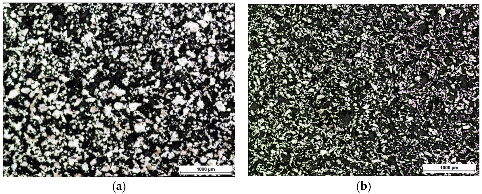
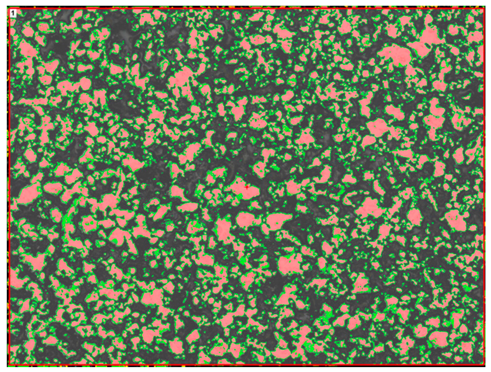
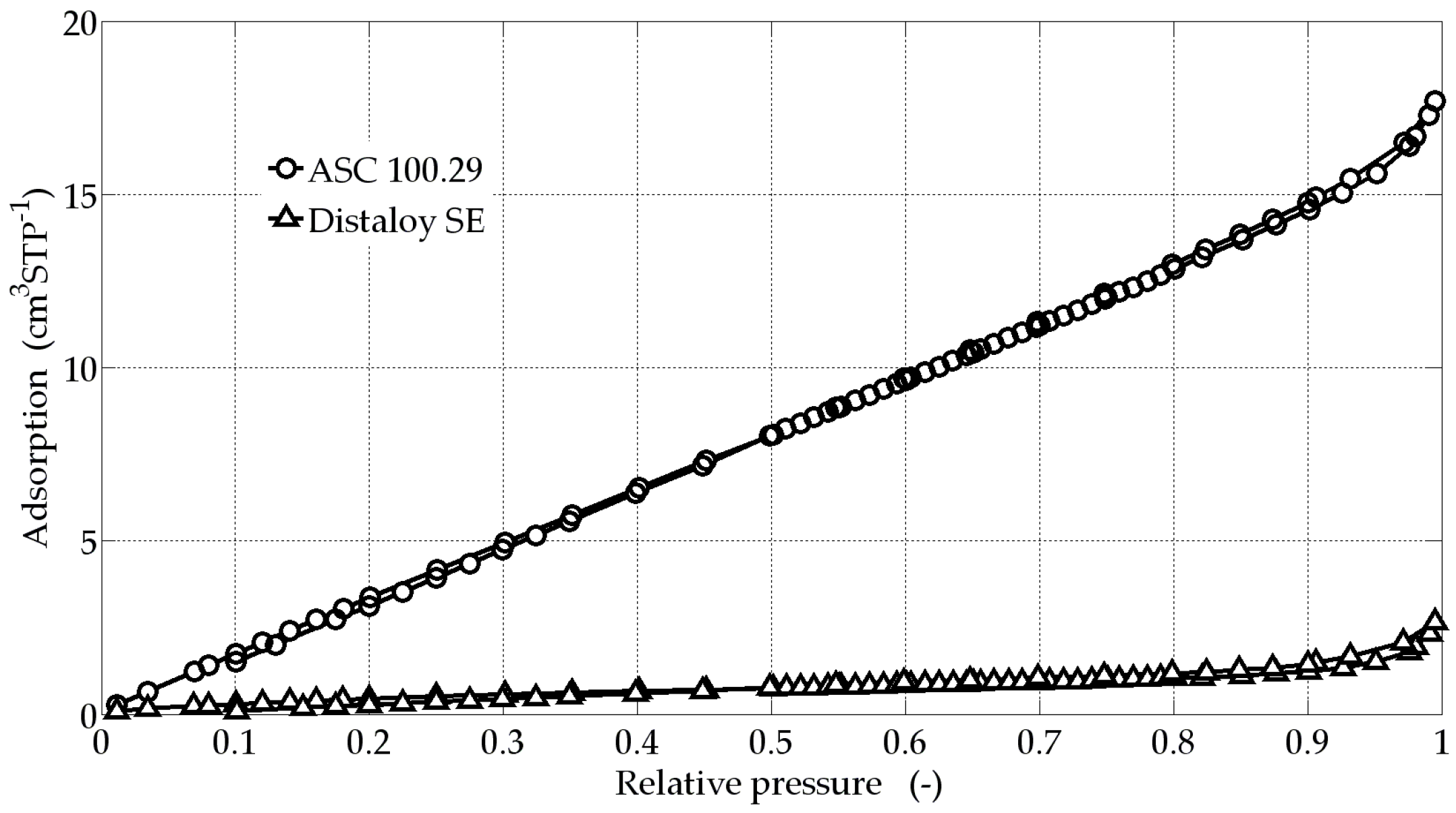
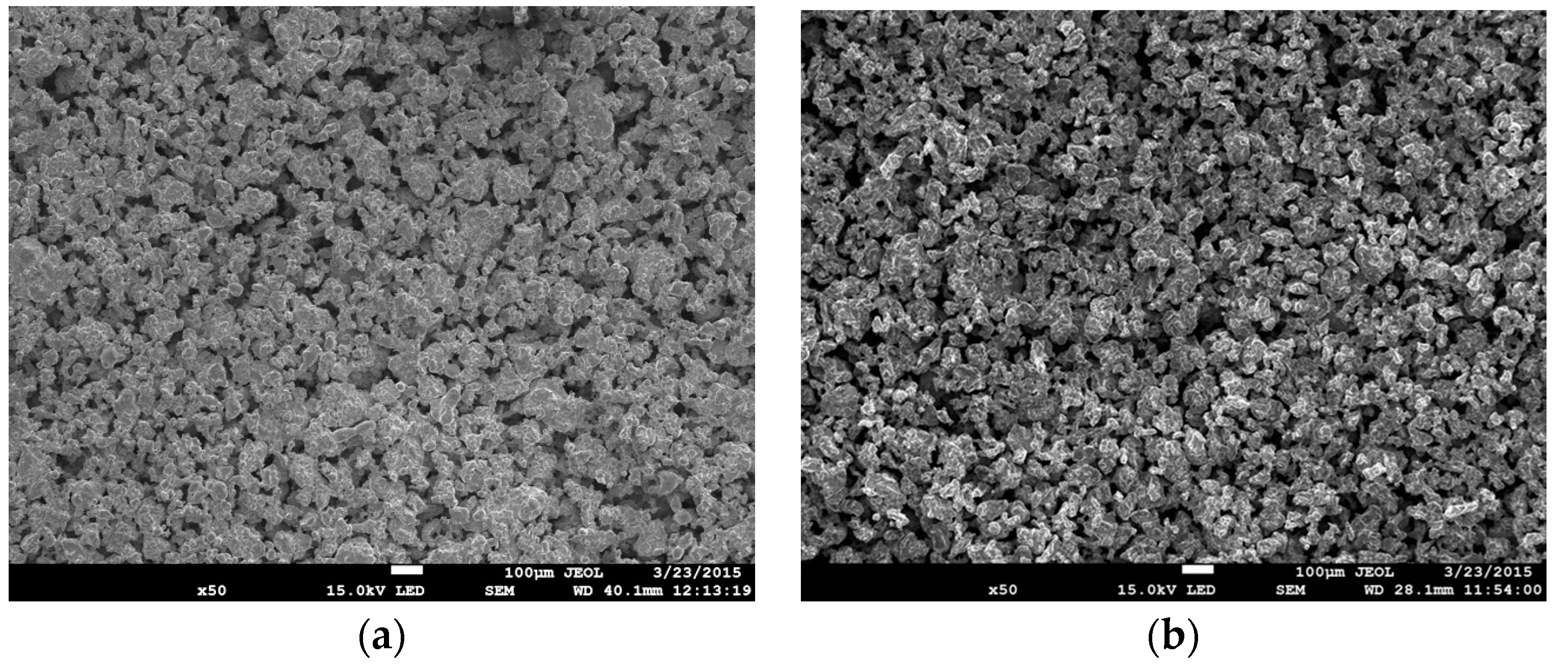
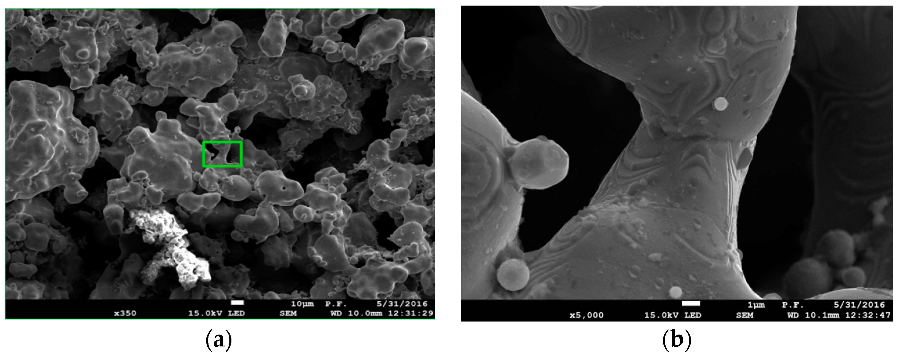
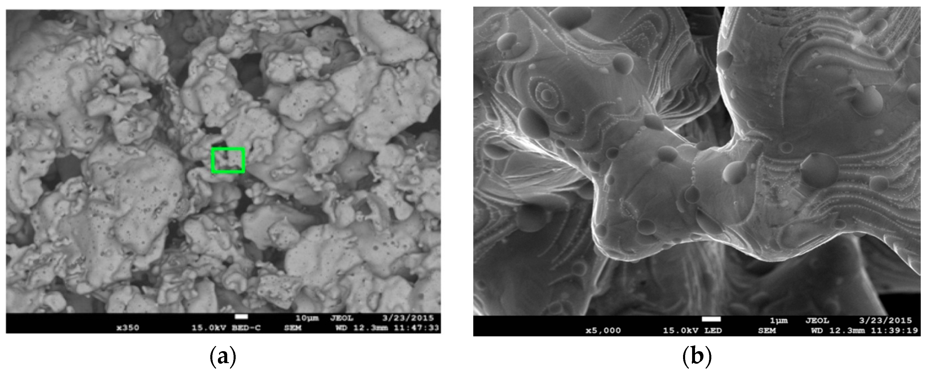
2. Results
3. Discussion
4. Materials and Methods
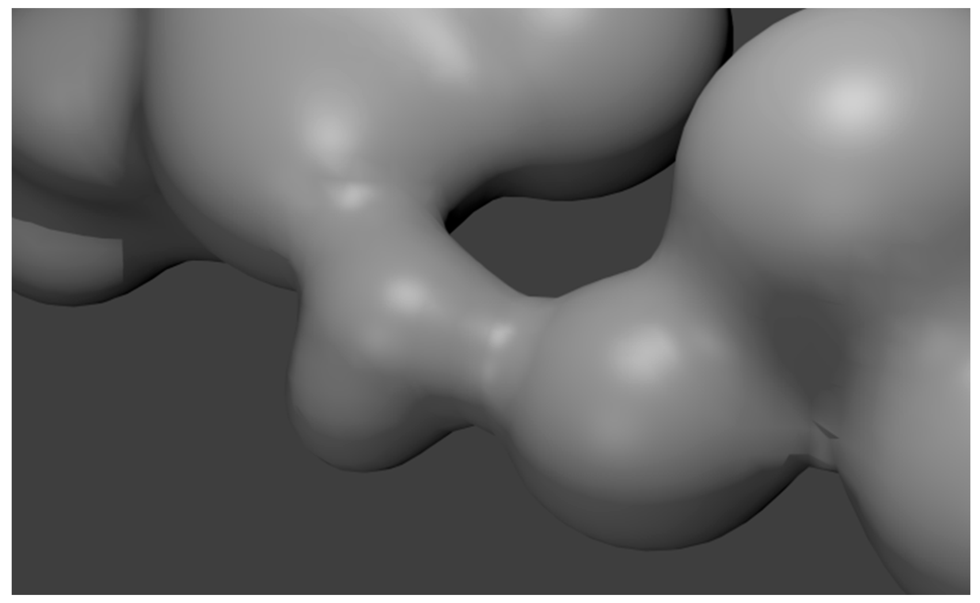
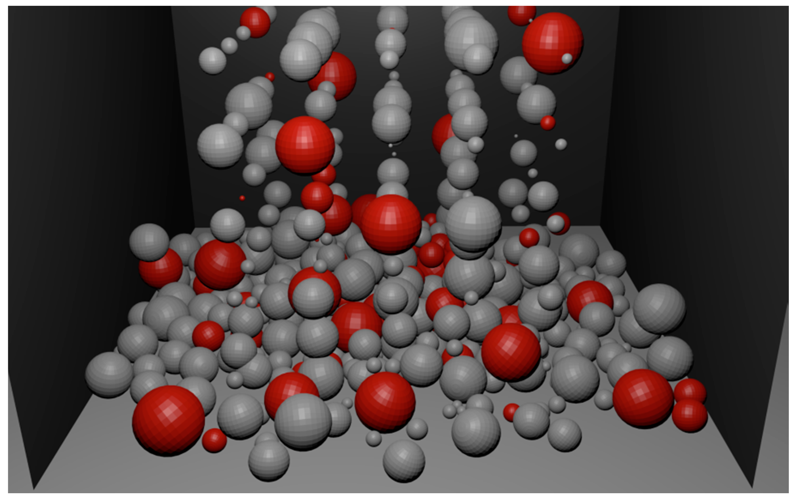
Modelling of the Metallic Porous Materials
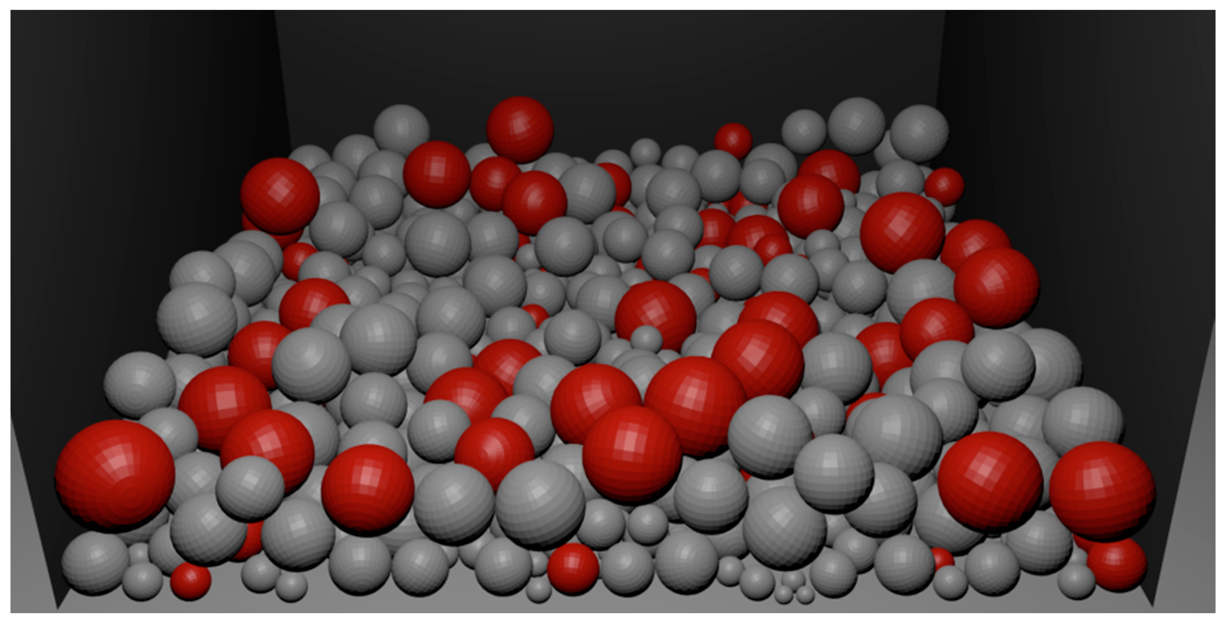
- generation of the iron and oxide particles with random size and distribution based on sieve analysis
- simulation of mixing and filling a container using physical modelling
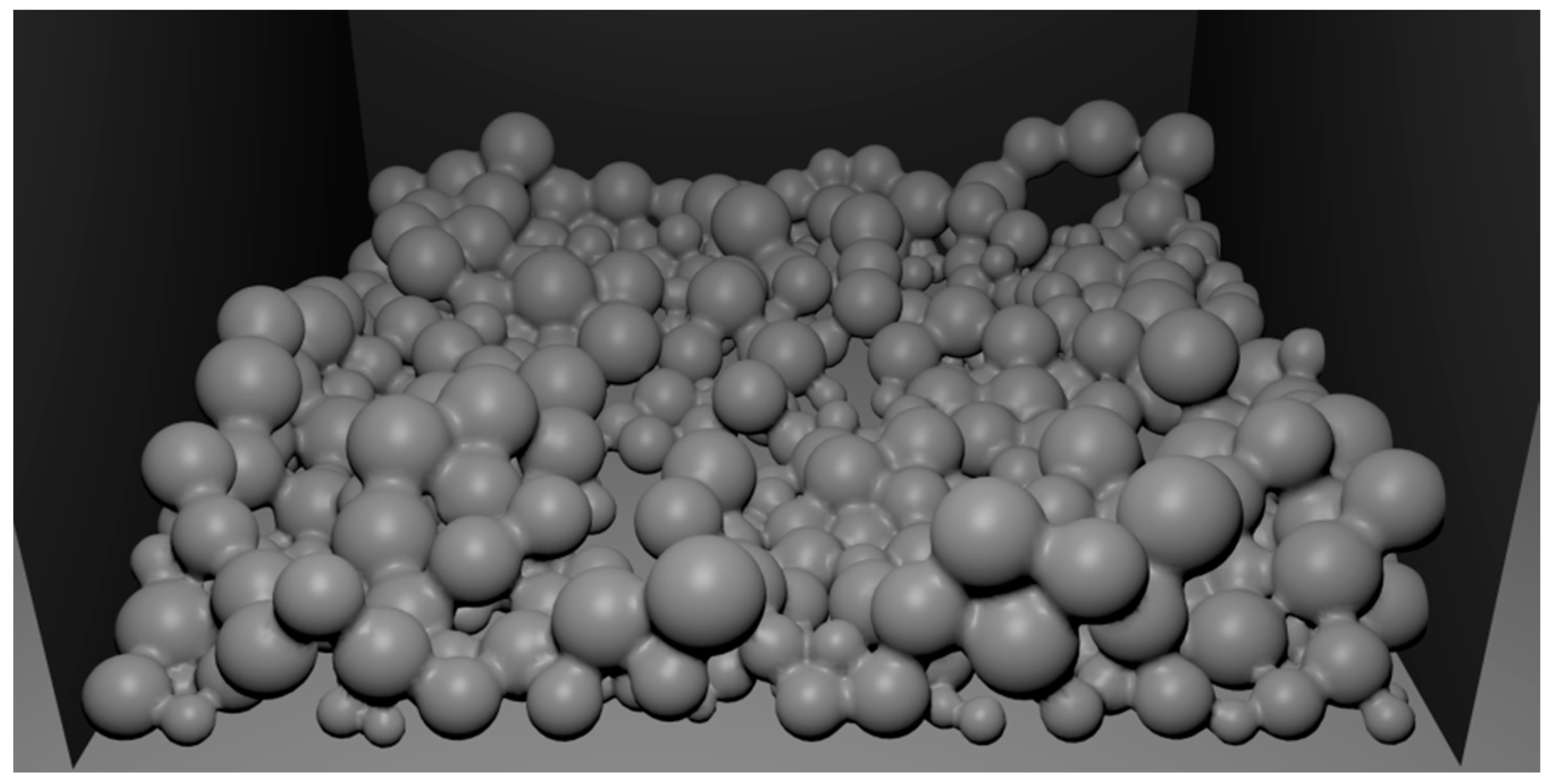
- removal of oxide balls, exchanging iron balls by metaballs of the correct size
- modelling of sintering by setting proper threshold value
5. Conclusions
Author Contributions
Conflicts of Interest
References
- Ashby, M.F.; Evans, A.G.; Fleck, N.A.; Gibson, L.J.; Hutchinson, J.W.; Wadley, H.N.G. Metal Foams: A Design Guide; Buterworth-Heineman: Boston, MA, USA, 2000. [Google Scholar]
- Arwade, S.R.; Hajjar, J.F.; Schafer, B.W.; Moradi, M.; Smith, B.H.; Szyniszewski, S. Steel foam material processing, properties and potential structural applications. In Structural Materials and Mechanics, Proceedings of the 2011 NSF Engineering Research and Innovation Conference, Atlanta, GA, USA, 4–7 January 2011; pp. 1–7.
- Garcia-Moreno, F. Commercial applications of metal foams: Their properties and production. Materials 2016. [Google Scholar] [CrossRef]
- Smith, B.H.; Szyniszewski, S.; Hajjar, J.F.; Schafer, B.W.; Arwade, S.R. Steel foam structures: A review of applications, manufacturing and material properties. J. Constr. Steel Res. 2012, 71, 1–10. [Google Scholar] [CrossRef]
- Boomsma, K.; Poulikakos, D.; Zwick, F. Metal foams as compact high performance heat exchangers. Mech. Mater. 2003, 35, 1161–1176. [Google Scholar] [CrossRef]
- Bednarova, V.; Lichy, P.; Lana, I.; Elbel, T. Casting routes porous metals with regular and irregular structure. Arch. Foundry Eng. 2012, 12, 71–74. [Google Scholar]
- Radford, D.D.; McShane, G.J.; Deshpande, V.S.; Fleck, N.A. The response of clamped sandwich plates with metallic foam cores to simulated blast loading. Int. J. Solids Struct. 2006, 43, 2243–2259. [Google Scholar] [CrossRef]
- Parvanian, A.M.; Sadatfar, M.; Panjepour, M.; Kingston, A.; Sheppard, A.P. The effects of manufacturing parameters on geometrical and mechanical properties of copper foams produced by space holder technique. Mater. Des. 2014, 53, 681–690. [Google Scholar] [CrossRef]
- Parvanian, A.M.; Panjepour, M. Mechanical behavior improvement of open pore copper foams synthesized trough space holder technique. Mater. Des. 2013, 49, 834–841. [Google Scholar] [CrossRef]
- Depczynski, W. Sintering of copper layers with a controlled porous structure. In Proceedings of the Metal 2014: 23rd International Conference on Metallurgy and Materials, Brno, Czech Republic, 21–23 May 2014; pp. 1219–1224.
- Rabiei, A.; Vendra, L.; Reese, N.; Young, N.; Neville, B.P. Processing and charakterization of new composite metal foam. Mater. Trans. 2006, 47, 2148–2153. [Google Scholar] [CrossRef]
- Yao, B.; Zhou, Z.; Duan, L.; Xiao, Z. Compressibility of 304 stainless steel powder metallurgy materials reinforced with 304 short stainless steel fibers. Materials 2016. [Google Scholar] [CrossRef]
- Młynarczyk, P.; Depczyński, W. The selected properties of fusion of Fe foam and sheet metal with the use of the Nd:YAG laser. J. Achiev. Manuf. Eng. 2014, 65, 68–72. [Google Scholar]
- Hangai, Y.; Koyama, S.; Hasegawa, M.; Utsonomiya, T. Fabrication of aluminum foam/dense steel composite by friction stir welding. Metal. Mater. Trans. 2010, 41, 2184–2186. [Google Scholar] [CrossRef]
- Hangai, Y.; Saito, M.; Utsunomiya, T.; Kitahara, S.; Kuwazuru, O.; Yoshikawa, N. Fabrication of aluminum foam filled thin wall steel tube by friction welding and its corrosion properties. Materials 2014, 7, 6796–6810. [Google Scholar] [CrossRef]
- Chatys, R.; Depczynski, W.; Zorawski, W. A Method of Producing Porous Structures. U.S. Patent 6,447,701 B1, 10 September 2002. (In Polish)[Google Scholar]
- Rybyanets, A.N. Porous piezoceramics: Theory, technology, and properties. IEEE Trans. Ultrason. Ferroelectr. Freq. Control 2011, 58, 1492–1507. [Google Scholar] [CrossRef] [PubMed]
- Selig, S.G.; Doman, D.A. A review of finite element simulations of metal powder die compaction. J. Mach. Manuf. Autom. 2014, 3, 32–40. [Google Scholar]
- Yang, C.; An, Y.; Greenfield, R.; Hodgson, P. 2-/3-D digital material representation and evaluation of metal foams. Comput. Methods Mater. Sci. 2013, 13, 425–435. [Google Scholar]
- Gawdzinska, K.; Grabian, J.; Gucma, M.; Kwiecinska, B. Deformation mechanisms in metal composite foams. Metalurgija 2016, 56, 37–40. [Google Scholar]
- Osher, J.; Schladitz, K. 3D images of materials structures. In Processing and Analysis; Viley-Vch Verlag-Gmbh & Co. KGaA: Weinheim, Germany, 2009. [Google Scholar]
- Muszka, P.; Graca, P.; Sitko, M.; Madej, L.; Sun, L. Application of the multiscale microstructure-based modelling techniques for the prediction of strain inhomogeneity in the non-linear deformation processes. Comput. Methods Mater. Sci. 2013, 13, 460–470. [Google Scholar]
- Redenbach, C. Microstructure models for cellular materials. Comput. Mater. Sci. 2009, 44, 1397–1407. [Google Scholar] [CrossRef]
- Parhami, F.; McMeeking, R.M.; Cocks, A.C.F.; Suo, Z. A model for sintering and coarsening of rows of spherical particles. Mech. Mater. 1999, 31, 43–61. [Google Scholar] [CrossRef]
- Kumar, V. Simulations and Modeling of Unequal Sized Particles Sintering. Ph.D. Thesis, The University of Utah, Salt Lake City, UT, USA, 2011. [Google Scholar]
- Gorshkov, V.; Kuzmenko, V.; Privman, V. Mechanisms of interparticle bridging in sintering of dispersed nanoparticles. J. Coupled Syst. Multiscale Dyn. 2014, 2, 91–99. [Google Scholar] [CrossRef]
- Tong, R.; Kaneda, K.; Yamashita, H. A volume preserving approach for modeling and animating water flows generated by metaballs. Vis. Comput. 2002, 18, 469–480. [Google Scholar] [CrossRef]
- Crawford, P. Extrusioncutter: A Novel System for Generating Interactive Context-Preserving Cutaways of Anatomical Surface Meshes 2010. Master’s Thesis, Ryerson University, Toronto, ON, Canada, 2010. [Google Scholar]
- Blender Reference Manual. Available online: http//www.blender.org/manual/modeling/metas/index.html (accessed on 17 April 2016).
- Murakami, T.; Ohara, K.; Narushima, T.; Ouchi, C. Development of a new method of manufacturing iron foam using gases generated by reduction of iron oxide. Mater. Trans. 2007, 48, 2937–2944. [Google Scholar] [CrossRef]
- Park, C.; Nutt, S.R. Effects of process parameter on steel foam synthesis. Mater. Sci. Eng. A 2001, 297, 62–68. [Google Scholar] [CrossRef]
- Chang-Lin, L.; Hui, W.; Xiang-Yang, Z. Debinding of stainless steel foam precursor with 3-D open-cell network structure. Trans. Nonferrous Metals Soc. China 2010, 20, 2340–2344. [Google Scholar]
- Bekoz, N.; Oktay, E. Mechanical properties of low alloy steel foams: Dependency on porosity and pore size. Mater. Sci. Eng. A 2013, 576, 82–90. [Google Scholar] [CrossRef]
- Gerber, M.; Poss, R.; Tillmann, A.; Walther, G.; Kieback, B.; Wolf, K.; Hanel, F. Fabrication and properties of stainless steel foams for sandwich panels. J. Sandw. Struct. Mater. 2012, 14, 181–196. [Google Scholar] [CrossRef]
- Romero, C.; Noyola, J.C.; Santiago, U.; Valladares, R.M.; Valladares, A.; Valladares, A.A. A new approach to the computer modelling of amorphous nanoporous structures of semiconducting and metallic materials: A review. Materials 2010, 3, 467–502. [Google Scholar] [CrossRef]
- Xia, R.; Wu, R.N.; Liu, Y.L.; Sun, X.Y. The role of computer simulation in nanoporous metals—A review. Materials 2015, 8, 5060–5083. [Google Scholar] [CrossRef]
- Bodla, K.K.; Garimella, S.V. Simulated microstructural evolution and design of porous sintered wicks. J. Heat Transf. 2014, 136, 1–10. [Google Scholar] [CrossRef]
- Rojek, J.; Pietrzak, K.; Chmielewski, M.; Kaliński, D.; Nosewicz, S. Discrete element simulation of powder sintering. Comput. Methods Mater. Sci. 2011, 11, 68–73. [Google Scholar]
- Bock, J.; Jacobi, A.M. Geometric classification of open-cell metal foams using X-ray micro-computed tomography. Mater. Charact. 2013, 75, 35–43. [Google Scholar] [CrossRef]
- Liu, P.S.; Chen, G.F. Porous Materials, Processing and Application; Butterworth-Heinemann: Oxford, UK, 2014; p. 533. [Google Scholar]
- Thommes, M.; Kaneko, K.; Neimark, A.V.; Olivier, J.P.; Reinoso, F.R.; Rouquerol, J.; Sing, K.S.W. Physisorption of gases, with special reference to the evaluation of surface area and pore size distribution (IUPAC Technical Report). Pure Appl. Chem. 2015, 87, 1051–1069. [Google Scholar] [CrossRef]
- Lowell, S.; Shields, J.E.; Thomas, M.A.; Thommes, M. Characterization of Porous Solids and Powders: Surface Area, Pore Size and Density, Chapter 3–4; Springer Science + Business Media: Dordrecht, The Netherlands, 2004; p. 339. [Google Scholar]


| Grain Structure (μm) | Sieve Analysis | |
|---|---|---|
| ASC 100.29 (%) | Distaloy SE (%) | |
| <45 | 18 | 22 |
| 45–150 | 65 | 76 |
| 150–180 | 17 | 2 |
| >180 | 0 | 0 |
| Powder | Chemical Composition (Mas. %) | Average Particle Size (μm) | ||||
|---|---|---|---|---|---|---|
| C | Cu | Ni | Mo | Fe | ||
| ASC 100.29 | <0.01 | - | - | - | Balanced | 45–180 |
| Distaloy SE | 1.5 | 4 | 0.5 | balanced | 45–180 | |
| Specimens | Composition (%) | |||
|---|---|---|---|---|
| ASC 100.29 | Distaloy SE | Cu | Iron (III) Oxide | |
| ASC 100.29 | 85 | - | 5 | 10 |
| Distaloy SE | - | 85 | 5 | 10 |
| Material | SBET (m2/g) | Vt (cm3/g) |
|---|---|---|
| ASC 100.29 | 26.975 | 0.0267 |
| Distaloy SE | 2.187 | 0.0036 |
© 2016 by the authors; licensee MDPI, Basel, Switzerland. This article is an open access article distributed under the terms and conditions of the Creative Commons Attribution (CC-BY) license (http://creativecommons.org/licenses/by/4.0/).
Share and Cite
Depczynski, W.; Kazala, R.; Ludwinek, K.; Jedynak, K. Modelling and Microstructural Characterization of Sintered Metallic Porous Materials. Materials 2016, 9, 567. https://doi.org/10.3390/ma9070567
Depczynski W, Kazala R, Ludwinek K, Jedynak K. Modelling and Microstructural Characterization of Sintered Metallic Porous Materials. Materials. 2016; 9(7):567. https://doi.org/10.3390/ma9070567
Chicago/Turabian StyleDepczynski, Wojciech, Robert Kazala, Krzysztof Ludwinek, and Katarzyna Jedynak. 2016. "Modelling and Microstructural Characterization of Sintered Metallic Porous Materials" Materials 9, no. 7: 567. https://doi.org/10.3390/ma9070567